EP4056503B1 - Apparatus and method for varying the pitch between moving articles - Google Patents
Apparatus and method for varying the pitch between moving articles Download PDFInfo
- Publication number
- EP4056503B1 EP4056503B1 EP21161713.9A EP21161713A EP4056503B1 EP 4056503 B1 EP4056503 B1 EP 4056503B1 EP 21161713 A EP21161713 A EP 21161713A EP 4056503 B1 EP4056503 B1 EP 4056503B1
- Authority
- EP
- European Patent Office
- Prior art keywords
- closed
- loop
- articles
- conveyor
- belt
- Prior art date
- Legal status (The legal status is an assumption and is not a legal conclusion. Google has not performed a legal analysis and makes no representation as to the accuracy of the status listed.)
- Active
Links
Images


Classifications
-
- B—PERFORMING OPERATIONS; TRANSPORTING
- B65—CONVEYING; PACKING; STORING; HANDLING THIN OR FILAMENTARY MATERIAL
- B65G—TRANSPORT OR STORAGE DEVICES, e.g. CONVEYORS FOR LOADING OR TIPPING, SHOP CONVEYOR SYSTEMS OR PNEUMATIC TUBE CONVEYORS
- B65G47/00—Article or material-handling devices associated with conveyors; Methods employing such devices
- B65G47/22—Devices influencing the relative position or the attitude of articles during transit by conveyors
- B65G47/26—Devices influencing the relative position or the attitude of articles during transit by conveyors arranging the articles, e.g. varying spacing between individual articles
- B65G47/30—Devices influencing the relative position or the attitude of articles during transit by conveyors arranging the articles, e.g. varying spacing between individual articles during transit by a series of conveyors
- B65G47/31—Devices influencing the relative position or the attitude of articles during transit by conveyors arranging the articles, e.g. varying spacing between individual articles during transit by a series of conveyors by varying the relative speeds of the conveyors forming the series
-
- B—PERFORMING OPERATIONS; TRANSPORTING
- B65—CONVEYING; PACKING; STORING; HANDLING THIN OR FILAMENTARY MATERIAL
- B65G—TRANSPORT OR STORAGE DEVICES, e.g. CONVEYORS FOR LOADING OR TIPPING, SHOP CONVEYOR SYSTEMS OR PNEUMATIC TUBE CONVEYORS
- B65G15/00—Conveyors having endless load-conveying surfaces, i.e. belts and like continuous members, to which tractive effort is transmitted by means other than endless driving elements of similar configuration
- B65G15/30—Belts or like endless load-carriers
- B65G15/32—Belts or like endless load-carriers made of rubber or plastics
- B65G15/42—Belts or like endless load-carriers made of rubber or plastics having ribs, ridges, or other surface projections
-
- B—PERFORMING OPERATIONS; TRANSPORTING
- B65—CONVEYING; PACKING; STORING; HANDLING THIN OR FILAMENTARY MATERIAL
- B65G—TRANSPORT OR STORAGE DEVICES, e.g. CONVEYORS FOR LOADING OR TIPPING, SHOP CONVEYOR SYSTEMS OR PNEUMATIC TUBE CONVEYORS
- B65G15/00—Conveyors having endless load-conveying surfaces, i.e. belts and like continuous members, to which tractive effort is transmitted by means other than endless driving elements of similar configuration
- B65G15/30—Belts or like endless load-carriers
- B65G15/58—Belts or like endless load-carriers with means for holding or retaining the loads in fixed position, e.g. magnetic
-
- B—PERFORMING OPERATIONS; TRANSPORTING
- B65—CONVEYING; PACKING; STORING; HANDLING THIN OR FILAMENTARY MATERIAL
- B65G—TRANSPORT OR STORAGE DEVICES, e.g. CONVEYORS FOR LOADING OR TIPPING, SHOP CONVEYOR SYSTEMS OR PNEUMATIC TUBE CONVEYORS
- B65G21/00—Supporting or protective framework or housings for endless load-carriers or traction elements of belt or chain conveyors
- B65G21/20—Means incorporated in, or attached to, framework or housings for guiding load-carriers, traction elements or loads supported on moving surfaces
- B65G21/2027—Suction retaining means
- B65G21/2036—Suction retaining means for retaining the load on the load-carrying surface
-
- B—PERFORMING OPERATIONS; TRANSPORTING
- B65—CONVEYING; PACKING; STORING; HANDLING THIN OR FILAMENTARY MATERIAL
- B65G—TRANSPORT OR STORAGE DEVICES, e.g. CONVEYORS FOR LOADING OR TIPPING, SHOP CONVEYOR SYSTEMS OR PNEUMATIC TUBE CONVEYORS
- B65G47/00—Article or material-handling devices associated with conveyors; Methods employing such devices
- B65G47/74—Feeding, transfer, or discharging devices of particular kinds or types
- B65G47/84—Star-shaped wheels or devices having endless travelling belts or chains, the wheels or devices being equipped with article-engaging elements
- B65G47/841—Devices having endless travelling belts or chains equipped with article-engaging elements
- B65G47/843—Devices having endless travelling belts or chains equipped with article-engaging elements the article-engaging elements being suction or magnetic means
Definitions
- the invention relates in general to manufacturing and/or packaging of articles moving at a high-speed in a production/packaging line.
- the invention relates to an apparatus and to a method for changing the pitch - operation also known as "pitch change” or "re-pitching" - between articles being conveyed.
- the invention has been developed with particular attention to the field of manufacturing or packaging of sanitary articles, such as sanitary pads, pantry liners, diapers, training pants, paper towels, female hygiene products, face masks, plasters, etc.
- rotary repitch apparatuses The main disadvantage of rotary repitch apparatuses is the need to provide a plurality of motors dedicated to several shoes for periodically accelerating and decelerating the shoes during rotation, thus making the apparatuses complex, cumbersome and expensive. Another disadvantage is the need to stock many spare parts.
- WO-2012/009491-A1 and US-6000528-A disclose different apparatuses for transferring articles, adapted to vary the linear speed of the articles conveyed on transport elements.
- the apparatus of WO-2012/009491-A1 comprises a first transfer surface driven by a first motor and second transfer surface driven by a second motor.
- the first and second transfer surfaces receive and transfer different portions of an article at different speeds such that a desired amount of spacing can be provided between discrete articles.
- the spacing between the trailing end of a previous article and the leading end of a subsequent article can be desirably controlled by adjusting the acceleration/deceleration of movable surfaces of the apparatus.
- US-6000528-A discloses an apparatus for varying the pitch between moving articles according the preamble of claim 1.
- US-6000528-A discloses moreover a method for varying the pitch between moving articles, including:- feeding a flow of articles along a machine direction spaced apart from each other in said machine direction by a first pitch, - receiving said flow of articles spaced apart from each other by said first pitch on a closed-loop central belt having a transport branch extending between an infeed section and an outfeed section,- retaining said articles on said transport branch of the closed-loop central belt by vacuum suction during the movement between the infeed section to the outfeed section, wherein said articles have a width in a direction transversal to said machine direction greater than the width of said closed-loop central belt so that said articles have lateral portions projecting laterally outside said closed-loop central belt, - driving said closed-loop central belt at
- the object of the present invention is to overcome the drawbacks and limitations of the prior art.
- Another object of the present invention is to provide an apparatus of the type indicated above, which ensures an excellent stability of the articles during the repitch operation.
- the invention relates to a method for changing the pitch between moving articles having the features of claim 11.
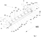
- an apparatus for varying the pitch between moving articles is indicated by the reference numeral 100.
- the apparatus 100 is configured to vary the pitch between adjacent articles A in a continuous flow of moving articles A advancing along a machine direction MD.
- the apparatus 100 comprises a phaser conveyor 1 having an infeed section 10 and an outfeed section 11, wherein the infeed section 10 is configured for receiving a flow of articles A which advance with a first pitch P1.
- the figures refer to a phaser conveyor 1 of the motor-driven-belt type.
- the apparatus 100 comprises an infeed conveyor 8 configured for feeding the phaser conveyor 1 with a flow of articles A along a machine direction MD, in which the articles A conveyed by the infeed conveyor 8 are spaced apart from each other in said machine direction MD by a first pitch P1. It is to be noted that the infeed conveyor 8 is described in detail in a subsequent section of this description.
- the phaser conveyor 1 comprises a central belt 2 having a transport branch 20' which extends along the machine direction MD.
- the central belt 2 is a closed-loop belt having a flat support surface 20 configured for receiving thereon the articles A.
- the closed-loop central belt 2 is wound about two pulleys 12, 13, at least one of which is driven by a first motor 5.
- the first motor 5 is configured to continuously drive the central belt 2 along the machine direction MD at a first speed V1.
- the phaser conveyor 1 comprises a plurality of idle support rollers 7 which support the transport branch 20' of the central belt 2.
- the apparatus 100 is configured to stably retain the articles A on the central belt 2 during transfer from a gripping position to a release position, and to stop the retaining action of the articles A in the release position.
- the apparatus 100 comprises a vacuum grip system including a stationary suction box 50 connected to a sub-atmospheric pressure source and having a suction surface facing the transport branch 20' of the closed-loop central belt 2.
- the closed-loop central belt 2 has a plurality of through holes 21 open on the flat support surface 20 and facing the stationary suction box 50, so as to provide a gripping condition for the articles A on the transport branch 20' during the movement from the infeed section 10 to the outfeed section 11.
- the vacuum gripping condition remains active to retain the articles A on the transport branch 20' during the path in which the through holes 21 face the stationary suction box 50, in the path from the infeed section 10 to the outfeed section 11.
- the phaser conveyor 1 comprises two closed-loop side belts 3, 4, having respective branches extending on opposite sides of the transport branch 20' of the central belt 2.
- the side belts 3, 4 have respective support surfaces 24, 25 which may be coplanar with the flat support surface 20 of the transport branch 20' of the central belt 2 to form a continuous surface for supporting and transporting the articles A.
- the width of the belts 2, 3, 4 in a direction transversal to the machine direction MD can be different from what is illustrated, depending on the size of the articles A to be conveyed.
- the side belts 3, 4 are driven by a second motor 6 configured to synchronously drive the side belts 3, 4 at a second speed V2 different from the first speed V1.
- the first speed V1 of the central belt 2 may be higher or lower than the second speed V2 of the side belts 3, 4.
- the side belts 3, 4 are wound on one side around two drive pulleys 15, 17 arranged on the same axis and powered by the second motor 6, and on the opposite side around two idle pulleys 14, 16 arranged on the same axis.
- the central belt 2 is a closed-loop belt wound around two pulleys 12, 13, at least one of which is driven by a first motor 5.
- the pulley 12 is a drive pulley arranged on the same axis of the idle pulleys 14, 16, and the pulley 13 is an idle pulley arranged on the same axis of the drive pulleys 15, 17.
- the side belts 3, 4 comprise respective rows of stop elements 30, 40 configured to engage side portions of said articles A projecting laterally outside the transport branch 20' of the central belt 2.
- the stop elements 30, 40 of each side belt 3, 4 are spaced apart from each other in the machine direction MD by a constant distance X.
- the stop elements 30, 40 of each side belt 3, 4 are aligned to the stop elements 30, 40 of the other belt 3, 4 in a direction transversal to the machine direction MD.
- the stop elements 30, 40 are ribs protruding from respective flat surfaces.
- the stop elements 30, 40 are ribs having a width in a direction transversal to the machine direction MD equal to the width of the side belts 3, 4.
- the phaser conveyor 1 transports articles A having a width in a direction transversal to the machine direction MD greater than the width of the central belt 2.
- the articles are retained by vacuum suction on the flat support surface 20 of the transport branch 20' of the central belt 2 and advance in the machine direction MD at the first speed V1 of the central belt 2.
- the difference between the first speed V1 of the central belt 2 and the second speed V2 of the side belts 3, 4 causes the articles A to come into contact with respective pairs of transversally aligned stop elements 30, 40.
- the articles A retained on the central belt 2 come into contact with respective pairs of stop elements 30, 40, they start to move in the machine direction MD at the second speed V2, so that they slide with respect to the flat support surface 20 of the central belt 2.
- the articles A are spaced apart from each other in the machine direction MD by a second pitch P2 corresponding to the distance X between the stop elements 30, 40.
- the speed V1 of the central belt 2 is higher than the second speed V2 of the side belts 3, 4. Consequently, in operation, an article A conveyed on the infeed section 10 of the phaser conveyor 1 reaches a pair of transversally aligned stop elements 30, 40 located in a more advanced position with respect to the article A, so as to make contact between a leading edge portion of the article A and said pair of transversally aligned stop elements 30, 40 at the outfeed section 11 of the phaser conveyor 1.
- the side belts 3, 4 are driven with a speed V2 higher than the speed V1 of the central belt 2 which retains the articles A. Consequently, in operation, an article A conveyed on the infeed section 10 of the phaser conveyor 1 is reached by a pair of transversally aligned stop elements 30, 40 located in a back position with respect to the article A, so as to make contact between a trailing edge portion of the article A and said pair of transversally aligned stop elements 30, 40 at the outfeed section 11 of the phaser conveyor 1.
- the lateral belts 3, 4 comprise a plurality of through holes facing the stationary suction box 50, so as to provide a gripping condition for the articles A on the support surfaces 24, 25 of the side belts 3, 4 during the movement from the infeed section 10 to the outfeed section 11.
- the retaining force is properly adjusted in order to give greater stability to articles A with respect to embodiments with through holes provided only on the central belt 2, but at the same time enabling sliding of the side belts 3, 4 under the articles A.
- the through holes on the side belts may be provided only on the portions adjacent to the stop elements 30, 40.
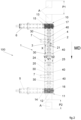
- the apparatus 100 comprises an infeed conveyor 8 - schematically illustrated in figure 4 - configured for feeding to the phaser conveyor 1 the articles A spaced apart from each other in said machine direction MD by the first pitch P1.
- the infeed conveyor 8 can be of the motor-driven-belt type.
- the infeed conveyor 8 comprises a closed-loop belt defining a downwardly facing transport branch 18 aligned with the central belt 2 along the machine direction MD and having a terminal end portion vertically overlapped to the transport branch 20' of the central belt 2 at the infeed section 10.
- the closed-loop belt of the infeed conveyor 8 has a width - in a direction transversal to said machine direction MD - substantially equal to the width of the central belt 2, so that said terminal end portion does not interfere with the stop elements 30, 40 of the side belts 3, 4.
- the transport branch 18 of the infeed conveyor 8 may have a width lower than the width of the central belt 2. In any case, if the infeed conveyor 8 is vertically superimposed on the central belt 2, the infeed conveyor 8 has to be arranged so as to not interfere with the stop elements 30, 40 of the side belts 3, 4.
- the infeed conveyor 8 comprises a vacuum grip system which is configured and controlled for holding the articles A conveyed by the infeed conveyor 8 against the downwardly facing transport branch 18 of the infeed conveyor 8 until the article A is released on, and gripped by, the central belt 2 of the phaser conveyor 1.
- the infeed conveyor 8 comprises a plurality of through holes 19 and a stationary suction box connected to a sub-atmospheric pressure source, so as to provide a sucking surface for retaining the conveyed articles A against said downwardly facing transport branch 18 of the infeed conveyor 8 until they are released on the phaser conveyor 1.
- the vacuum gripping condition of the infeed conveyor 8 remains active to retain the articles A on the transport branch 18 during the path in which the through holes 19 are faced to a stationary suction box.
- the interruption of the retaining action of the infeed conveyor 8 is phased with the beginning of the retaining action of the phaser conveyor 1 at the infeed section 10.
- the infeed conveyor 8 is phased with the side belts 3, 4, so that the articles A are passed on the infeed section 10 of the phaser conveyor 1 in a position between two consecutive stop elements 30, 40.
- the presence of the stop elements 30, 40 only on the side belts 3, 4 enables using an infeed conveyor 8 arranged above and between the side belts 3, 4, which does not interfere with the stop elements 30, 40, which ensures a smooth transition of the articles A from the infeed conveyor 8 to the phaser conveyor 1.
- the apparatus comprises an outfeed conveyor 9 operatively connected to the outfeed section 11 of the phaser conveyor 1, arranged for receiving and transporting the articles A spaced by the second pitch P2, after the repitching operation carried out on the phaser conveyor 1.
- the outfeed conveyor 9 can be arranged similarly to the infeed conveyor 8 previously described.
- the outfeed conveyor 9 is also arranged so as to avoid interference with the stop elements 30, 40 of the side belts 3, 4.
- the outfeed conveyor 9 comprises a closed-loop belt defining a downwardly facing transport branch 22 aligned with the central belt 2 along the machine direction MD and having a first portion vertically overlapped on the transport branch 20' of the central belt 2 at the outfeed section 11.
- the closed-loop belt of the outfeed conveyor 9 has a width - in a direction transversal to said machine direction MD - substantially equal to the width of the central belt 2, so that it does not interfere with the stop elements 30, 40 of the side belts 3, 4.
- the outfeed conveyor 9 comprises a vacuum grip system comprising a plurality of through holes 23 formed in the belt of the outfeed conveyor 9, configured and controlled for holding each article A conveyed by the outfeed conveyor 9 against said downwardly facing transport branch 22 of the outfeed conveyor 9. It is to be noted that the interruption of the retaining action of the phaser conveyor 1 at the outfeed section 11 is phased with the beginning of the retaining action of the outfeed conveyor 9.
- the inlet and outfeed conveyors 8, 9 provide an effective transport of the articles A to and from the phaser conveyor 1, without interference with the stop elements 30, 40.
- the presence of the stop elements 30, 40 only on the side belts 3, 4 enables infeed and outfeed conveyors 8, 9 arranged above and between the side belts 3, 4, in order to guarantee a smooth transition of the articles A .
- the present invention provides a solution capable to vary the pitch of a flow of moving articles A in a simple and automatic way, ensuring an effective transport of articles of different types.
- the invention provides a solution which is much simpler and energy-efficient, which has a positive impact on sustainability.
Landscapes
- Engineering & Computer Science (AREA)
- Mechanical Engineering (AREA)
- Attitude Control For Articles On Conveyors (AREA)
Priority Applications (5)
| Application Number | Priority Date | Filing Date | Title |
|---|---|---|---|
| ES21161713T ES3028661T3 (en) | 2021-03-10 | 2021-03-10 | Apparatus and method for varying the pitch between moving articles |
| PL21161713.9T PL4056503T3 (pl) | 2021-03-10 | 2021-03-10 | Aparat i sposób do zmieniania odstępu pomiędzy przemieszczającymi się artykułami |
| EP21161713.9A EP4056503B1 (en) | 2021-03-10 | 2021-03-10 | Apparatus and method for varying the pitch between moving articles |
| US17/688,089 US11905123B2 (en) | 2021-03-10 | 2022-03-07 | Apparatus and method for varying the pitch between moving articles |
| CN202210231746.8A CN115072347A (zh) | 2021-03-10 | 2022-03-10 | 用于改变移动的物品之间的间距的设备和方法 |
Applications Claiming Priority (1)
| Application Number | Priority Date | Filing Date | Title |
|---|---|---|---|
| EP21161713.9A EP4056503B1 (en) | 2021-03-10 | 2021-03-10 | Apparatus and method for varying the pitch between moving articles |
Publications (3)
| Publication Number | Publication Date |
|---|---|
| EP4056503A1 EP4056503A1 (en) | 2022-09-14 |
| EP4056503B1 true EP4056503B1 (en) | 2025-05-07 |
| EP4056503C0 EP4056503C0 (en) | 2025-05-07 |
Family
ID=74870682
Family Applications (1)
| Application Number | Title | Priority Date | Filing Date |
|---|---|---|---|
| EP21161713.9A Active EP4056503B1 (en) | 2021-03-10 | 2021-03-10 | Apparatus and method for varying the pitch between moving articles |
Country Status (5)
| Country | Link |
|---|---|
| US (1) | US11905123B2 (pl) |
| EP (1) | EP4056503B1 (pl) |
| CN (1) | CN115072347A (pl) |
| ES (1) | ES3028661T3 (pl) |
| PL (1) | PL4056503T3 (pl) |
Families Citing this family (1)
| Publication number | Priority date | Publication date | Assignee | Title |
|---|---|---|---|---|
| CN111392390A (zh) * | 2020-03-17 | 2020-07-10 | 广东乐佳印刷有限公司 | 一种彩票卷转移装置 |
Family Cites Families (27)
| Publication number | Priority date | Publication date | Assignee | Title |
|---|---|---|---|---|
| US3728191A (en) | 1971-03-19 | 1973-04-17 | Kimberly Clark Co | Waistband tape application for disposable diapers |
| IT1188972B (it) | 1980-12-12 | 1988-01-28 | Gd Spa | Dispositivo di trasferimento per articoli a forma di barretta |
| IT1171559B (it) | 1981-09-29 | 1987-06-10 | Gd Spa | Dispositivo ribaltatore per articoli a forma di barretta in particolare sigarette |
| DE3515992A1 (de) * | 1985-05-03 | 1986-11-06 | Max Kettner Verpackungsmaschinenfabrik GmbH & Co KG, 8000 München | Foerdereinrichtung zur gesteuerten zufuhr von gegenstaenden zu einer bearbeitungsmaschine |
| DE3662592D1 (en) * | 1985-06-26 | 1989-05-03 | Sig Schweiz Industrieges | Apparatus for separating articles being in contact with each other |
| US4726876A (en) | 1985-10-18 | 1988-02-23 | Kimberly-Clark Corporation | Apparatus for repositioning discrete articles |
| SE462333B (sv) | 1987-01-23 | 1990-06-11 | Moelnlycke Ab | Anordning foer att oeverfoera artiklar fraan en foersta till en andra transportbana |
| DE3814341C1 (en) * | 1988-04-28 | 1989-03-09 | Effem Gmbh, 2810 Verden, De | Process and apparatus for the outward transfer of horizontal cans consisting of a magnetic material in can-filling systems |
| US5341915A (en) * | 1992-11-06 | 1994-08-30 | Kliklok Corporation | Article phasing, transfer and squaring system for packaging line |
| DE4302575A1 (de) * | 1993-01-29 | 1994-08-04 | Pactec Dresden Gmbh | Einrichtung zum Zuführen kleiner empfindlicher Stückgüter |
| IT1266343B1 (it) | 1993-05-07 | 1996-12-27 | Gd Spa | Dispositivo di cambio-passo per una successione ordinata di elementi. |
| DE19522264A1 (de) * | 1995-03-21 | 1996-09-26 | Datev Datenverarbeitungsorgani | Verfahren und Vorrichtung zum Fördern von Stückgut insbesondere in einer Verpackungsanordnung |
| EP0885823A1 (en) * | 1997-06-20 | 1998-12-23 | Klöckner Hänsel Tevopharm B.V. | Conveyor device for accelerating a series of products |
| NL1006370C2 (nl) * | 1997-06-20 | 1998-12-22 | Kloeckner Haensel Tevopharm | Transportinrichting voor het versnellen van een reeks producten. |
| US6044959A (en) * | 1998-11-12 | 2000-04-04 | Roberts Polypro, Inc. | Apparatus for staging (pitching) articles on a conveyor system |
| US6273238B1 (en) * | 2000-01-14 | 2001-08-14 | Batching Systems, Inc. | Apparatus and method for separating adjacent objects on a conveyor |
| EP1179495A1 (en) | 2000-08-11 | 2002-02-13 | Fameccanica.Data S.p.A. | A device for varying the pitch of articles being conveyed |
| DE10204933A1 (de) * | 2002-02-07 | 2003-08-21 | Rovema Gmbh | Vorrichtung zum Transportieren von stückigem Produkt |
| US6951271B2 (en) * | 2004-01-09 | 2005-10-04 | Roberts Polypro | Flight lug |
| CN101466621B (zh) * | 2006-06-15 | 2012-05-23 | 莱特拉姆有限责任公司 | 旋转物品的带式输送机 |
| FR2905117B1 (fr) * | 2006-08-24 | 2009-04-17 | Sidel Participations | Agencement pour le regroupement en rang de produits d'un lot sur un tapis de convoyage a haute cadence |
| DK1947037T3 (da) * | 2007-01-17 | 2009-11-23 | Fameccanica Data Spa | Indretning til at ændre forholdet mellem artikler, der transporteres, og drejning af disse artikler |
| WO2012009491A1 (en) | 2010-07-15 | 2012-01-19 | The Procter & Gamble Company | Method and apparatus for transferring articles of different sizes |
| CN202687474U (zh) * | 2012-03-30 | 2013-01-23 | 尤妮佳股份有限公司 | 吸收性物品输送路径变换装置 |
| EP3336023B1 (en) * | 2016-12-15 | 2019-06-26 | Fameccanica.Data S.p.A. | Apparatus for varying the pitch between moving articles |
| CN108773624A (zh) * | 2018-06-01 | 2018-11-09 | 三峡大学 | 一种粽叶上料装置 |
| CN209455686U (zh) * | 2019-01-16 | 2019-10-01 | 良记造机工厂有限公司 | 金属薄片的集料装置 |
-
2021
- 2021-03-10 ES ES21161713T patent/ES3028661T3/es active Active
- 2021-03-10 EP EP21161713.9A patent/EP4056503B1/en active Active
- 2021-03-10 PL PL21161713.9T patent/PL4056503T3/pl unknown
-
2022
- 2022-03-07 US US17/688,089 patent/US11905123B2/en active Active
- 2022-03-10 CN CN202210231746.8A patent/CN115072347A/zh active Pending
Also Published As
| Publication number | Publication date |
|---|---|
| US11905123B2 (en) | 2024-02-20 |
| EP4056503A1 (en) | 2022-09-14 |
| CN115072347A (zh) | 2022-09-20 |
| PL4056503T3 (pl) | 2025-06-23 |
| US20220289498A1 (en) | 2022-09-15 |
| EP4056503C0 (en) | 2025-05-07 |
| ES3028661T3 (en) | 2025-06-19 |
Similar Documents
| Publication | Publication Date | Title |
|---|---|---|
| US5221079A (en) | Apparatus for braking a succession of sheets to be stacked | |
| EP0894752A1 (en) | Conveyor device for accelerating a series of products | |
| US5348285A (en) | Hold-down device on handling machines, in particular punching machines, for thin, flat objects in particular sheets of paper | |
| US6230596B1 (en) | Method of and apparatus for conveying flat pieces of a web | |
| JPH0578000A (ja) | 鱗状に重り合つた一連の物品の形成装置 | |
| EP0885823A1 (en) | Conveyor device for accelerating a series of products | |
| AU2004297047B2 (en) | Device and method for eliminating trimmings from series of products, such as rolls or the like | |
| JPH01203137A (ja) | シート状印刷物の搬送装置 | |
| CN106660711B (zh) | 用于输送块式产品的方法和装置 | |
| EP4056503B1 (en) | Apparatus and method for varying the pitch between moving articles | |
| WO2012064277A1 (en) | Transition device | |
| US6273238B1 (en) | Apparatus and method for separating adjacent objects on a conveyor | |
| EP0538765B1 (en) | Method and device for forming groups of flat products, in particular biscuits, for supply to a packing line | |
| EP0519401B1 (en) | Device for equally-spaced in-line transportation of randomly arranged incoming products | |
| WO1991007343A1 (en) | Apparatus and method for separating a stream of lapped signatures into discrete batches | |
| US6994206B2 (en) | Apparatus for feeding rolls of cut products to a wrapper | |
| WO2012156477A1 (en) | Device and method for removing trims from a series of products such as rolls or the like | |
| EP0936991B1 (en) | Carton blank transport apparatus | |
| JP2001354348A (ja) | 物品を供給するための装置および方法 | |
| EP1511602B1 (en) | Device for eliminating end trimmings from a roll or the like | |
| KR102814931B1 (ko) | 시트 처리기 | |
| US20010007299A1 (en) | Process for conveying articles, for instance for automated packaging installations, and a device therefor | |
| JP7751212B2 (ja) | 物品搬送装置 | |
| EP1503939B1 (en) | Feeding device of chocolates and similar products | |
| US12545526B2 (en) | Method and apparatus for grouping and/or separating products transported in rows |
Legal Events
| Date | Code | Title | Description |
|---|---|---|---|
| PUAI | Public reference made under article 153(3) epc to a published international application that has entered the european phase |
Free format text: ORIGINAL CODE: 0009012 |
|
| STAA | Information on the status of an ep patent application or granted ep patent |
Free format text: STATUS: THE APPLICATION HAS BEEN PUBLISHED |
|
| AK | Designated contracting states |
Kind code of ref document: A1 Designated state(s): AL AT BE BG CH CY CZ DE DK EE ES FI FR GB GR HR HU IE IS IT LI LT LU LV MC MK MT NL NO PL PT RO RS SE SI SK SM TR |
|
| STAA | Information on the status of an ep patent application or granted ep patent |
Free format text: STATUS: REQUEST FOR EXAMINATION WAS MADE |
|
| 17P | Request for examination filed |
Effective date: 20230216 |
|
| RBV | Designated contracting states (corrected) |
Designated state(s): AL AT BE BG CH CY CZ DE DK EE ES FI FR GB GR HR HU IE IS IT LI LT LU LV MC MK MT NL NO PL PT RO RS SE SI SK SM TR |
|
| GRAP | Despatch of communication of intention to grant a patent |
Free format text: ORIGINAL CODE: EPIDOSNIGR1 |
|
| STAA | Information on the status of an ep patent application or granted ep patent |
Free format text: STATUS: GRANT OF PATENT IS INTENDED |
|
| RIC1 | Information provided on ipc code assigned before grant |
Ipc: B65G 47/84 20060101ALI20241105BHEP Ipc: B65G 47/31 20060101ALI20241105BHEP Ipc: B65G 21/20 20060101ALI20241105BHEP Ipc: B65G 15/58 20060101ALI20241105BHEP Ipc: B65G 15/42 20060101AFI20241105BHEP |
|
| INTG | Intention to grant announced |
Effective date: 20241203 |
|
| GRAS | Grant fee paid |
Free format text: ORIGINAL CODE: EPIDOSNIGR3 |
|
| GRAA | (expected) grant |
Free format text: ORIGINAL CODE: 0009210 |
|
| STAA | Information on the status of an ep patent application or granted ep patent |
Free format text: STATUS: THE PATENT HAS BEEN GRANTED |
|
| AK | Designated contracting states |
Kind code of ref document: B1 Designated state(s): AL AT BE BG CH CY CZ DE DK EE ES FI FR GB GR HR HU IE IS IT LI LT LU LV MC MK MT NL NO PL PT RO RS SE SI SK SM TR |
|
| REG | Reference to a national code |
Ref country code: GB Ref legal event code: FG4D |
|
| REG | Reference to a national code |
Ref country code: CH Ref legal event code: EP |
|
| REG | Reference to a national code |
Ref country code: DE Ref legal event code: R096 Ref document number: 602021030242 Country of ref document: DE |
|
| REG | Reference to a national code |
Ref country code: IE Ref legal event code: FG4D |
|
| U01 | Request for unitary effect filed |
Effective date: 20250509 |
|
| U07 | Unitary effect registered |
Designated state(s): AT BE BG DE DK EE FI FR IT LT LU LV MT NL PT RO SE SI Effective date: 20250516 |
|
| REG | Reference to a national code |
Ref country code: ES Ref legal event code: FG2A Ref document number: 3028661 Country of ref document: ES Kind code of ref document: T3 Effective date: 20250619 |
|
| PG25 | Lapsed in a contracting state [announced via postgrant information from national office to epo] |
Ref country code: NO Free format text: LAPSE BECAUSE OF FAILURE TO SUBMIT A TRANSLATION OF THE DESCRIPTION OR TO PAY THE FEE WITHIN THE PRESCRIBED TIME-LIMIT Effective date: 20250807 Ref country code: GR Free format text: LAPSE BECAUSE OF FAILURE TO SUBMIT A TRANSLATION OF THE DESCRIPTION OR TO PAY THE FEE WITHIN THE PRESCRIBED TIME-LIMIT Effective date: 20250808 |
|
| PG25 | Lapsed in a contracting state [announced via postgrant information from national office to epo] |
Ref country code: HR Free format text: LAPSE BECAUSE OF FAILURE TO SUBMIT A TRANSLATION OF THE DESCRIPTION OR TO PAY THE FEE WITHIN THE PRESCRIBED TIME-LIMIT Effective date: 20250507 |
|
| PG25 | Lapsed in a contracting state [announced via postgrant information from national office to epo] |
Ref country code: RS Free format text: LAPSE BECAUSE OF FAILURE TO SUBMIT A TRANSLATION OF THE DESCRIPTION OR TO PAY THE FEE WITHIN THE PRESCRIBED TIME-LIMIT Effective date: 20250807 |
|
| PG25 | Lapsed in a contracting state [announced via postgrant information from national office to epo] |
Ref country code: IS Free format text: LAPSE BECAUSE OF FAILURE TO SUBMIT A TRANSLATION OF THE DESCRIPTION OR TO PAY THE FEE WITHIN THE PRESCRIBED TIME-LIMIT Effective date: 20250907 |
|
| PG25 | Lapsed in a contracting state [announced via postgrant information from national office to epo] |
Ref country code: SM Free format text: LAPSE BECAUSE OF FAILURE TO SUBMIT A TRANSLATION OF THE DESCRIPTION OR TO PAY THE FEE WITHIN THE PRESCRIBED TIME-LIMIT Effective date: 20250507 |
|
| PG25 | Lapsed in a contracting state [announced via postgrant information from national office to epo] |
Ref country code: SK Free format text: LAPSE BECAUSE OF FAILURE TO SUBMIT A TRANSLATION OF THE DESCRIPTION OR TO PAY THE FEE WITHIN THE PRESCRIBED TIME-LIMIT Effective date: 20250507 |
|
| PLBE | No opposition filed within time limit |
Free format text: ORIGINAL CODE: 0009261 |
|
| STAA | Information on the status of an ep patent application or granted ep patent |
Free format text: STATUS: NO OPPOSITION FILED WITHIN TIME LIMIT |
|
| REG | Reference to a national code |
Ref country code: CH Ref legal event code: L10 Free format text: ST27 STATUS EVENT CODE: U-0-0-L10-L00 (AS PROVIDED BY THE NATIONAL OFFICE) Effective date: 20260318 |