EP4056408B1 - Batteriepack und elektrisches fahrzeug - Google Patents
Batteriepack und elektrisches fahrzeug Download PDFInfo
- Publication number
- EP4056408B1 EP4056408B1 EP20893130.3A EP20893130A EP4056408B1 EP 4056408 B1 EP4056408 B1 EP 4056408B1 EP 20893130 A EP20893130 A EP 20893130A EP 4056408 B1 EP4056408 B1 EP 4056408B1
- Authority
- EP
- European Patent Office
- Prior art keywords
- cells
- battery pack
- side frame
- plate
- cell
- Prior art date
- Legal status (The legal status is an assumption and is not a legal conclusion. Google has not performed a legal analysis and makes no representation as to the accuracy of the status listed.)
- Active
Links
Images


Classifications
-
- B—PERFORMING OPERATIONS; TRANSPORTING
- B60—VEHICLES IN GENERAL
- B60K—ARRANGEMENT OR MOUNTING OF PROPULSION UNITS OR OF TRANSMISSIONS IN VEHICLES; ARRANGEMENT OR MOUNTING OF PLURAL DIVERSE PRIME-MOVERS IN VEHICLES; AUXILIARY DRIVES FOR VEHICLES; INSTRUMENTATION OR DASHBOARDS FOR VEHICLES; ARRANGEMENTS IN CONNECTION WITH COOLING, AIR INTAKE, GAS EXHAUST OR FUEL SUPPLY OF PROPULSION UNITS IN VEHICLES
- B60K1/00—Arrangement or mounting of electrical propulsion units
- B60K1/04—Arrangement or mounting of electrical propulsion units of the electric storage means for propulsion
-
- H—ELECTRICITY
- H01—ELECTRIC ELEMENTS
- H01M—PROCESSES OR MEANS, e.g. BATTERIES, FOR THE DIRECT CONVERSION OF CHEMICAL ENERGY INTO ELECTRICAL ENERGY
- H01M50/00—Constructional details or processes of manufacture of the non-active parts of electrochemical cells other than fuel cells, e.g. hybrid cells
- H01M50/20—Mountings; Secondary casings or frames; Racks, modules or packs; Suspension devices; Shock absorbers; Transport or carrying devices; Holders
- H01M50/204—Racks, modules or packs for multiple batteries or multiple cells
- H01M50/207—Racks, modules or packs for multiple batteries or multiple cells characterised by their shape
- H01M50/209—Racks, modules or packs for multiple batteries or multiple cells characterised by their shape adapted for prismatic or rectangular cells
-
- H—ELECTRICITY
- H01—ELECTRIC ELEMENTS
- H01M—PROCESSES OR MEANS, e.g. BATTERIES, FOR THE DIRECT CONVERSION OF CHEMICAL ENERGY INTO ELECTRICAL ENERGY
- H01M50/00—Constructional details or processes of manufacture of the non-active parts of electrochemical cells other than fuel cells, e.g. hybrid cells
- H01M50/20—Mountings; Secondary casings or frames; Racks, modules or packs; Suspension devices; Shock absorbers; Transport or carrying devices; Holders
- H01M50/233—Mountings; Secondary casings or frames; Racks, modules or packs; Suspension devices; Shock absorbers; Transport or carrying devices; Holders characterised by physical properties of casings or racks, e.g. dimensions
- H01M50/236—Hardness
-
- H—ELECTRICITY
- H01—ELECTRIC ELEMENTS
- H01M—PROCESSES OR MEANS, e.g. BATTERIES, FOR THE DIRECT CONVERSION OF CHEMICAL ENERGY INTO ELECTRICAL ENERGY
- H01M50/00—Constructional details or processes of manufacture of the non-active parts of electrochemical cells other than fuel cells, e.g. hybrid cells
- H01M50/20—Mountings; Secondary casings or frames; Racks, modules or packs; Suspension devices; Shock absorbers; Transport or carrying devices; Holders
- H01M50/244—Secondary casings; Racks; Suspension devices; Carrying devices; Holders characterised by their mounting method
-
- H—ELECTRICITY
- H01—ELECTRIC ELEMENTS
- H01M—PROCESSES OR MEANS, e.g. BATTERIES, FOR THE DIRECT CONVERSION OF CHEMICAL ENERGY INTO ELECTRICAL ENERGY
- H01M50/00—Constructional details or processes of manufacture of the non-active parts of electrochemical cells other than fuel cells, e.g. hybrid cells
- H01M50/20—Mountings; Secondary casings or frames; Racks, modules or packs; Suspension devices; Shock absorbers; Transport or carrying devices; Holders
- H01M50/249—Mountings; Secondary casings or frames; Racks, modules or packs; Suspension devices; Shock absorbers; Transport or carrying devices; Holders specially adapted for aircraft or vehicles, e.g. cars or trains
-
- H—ELECTRICITY
- H01—ELECTRIC ELEMENTS
- H01M—PROCESSES OR MEANS, e.g. BATTERIES, FOR THE DIRECT CONVERSION OF CHEMICAL ENERGY INTO ELECTRICAL ENERGY
- H01M50/00—Constructional details or processes of manufacture of the non-active parts of electrochemical cells other than fuel cells, e.g. hybrid cells
- H01M50/20—Mountings; Secondary casings or frames; Racks, modules or packs; Suspension devices; Shock absorbers; Transport or carrying devices; Holders
- H01M50/258—Modular batteries; Casings provided with means for assembling
- H01M50/26—Assemblies sealed to each other in a non-detachable manner
-
- H—ELECTRICITY
- H01—ELECTRIC ELEMENTS
- H01M—PROCESSES OR MEANS, e.g. BATTERIES, FOR THE DIRECT CONVERSION OF CHEMICAL ENERGY INTO ELECTRICAL ENERGY
- H01M50/00—Constructional details or processes of manufacture of the non-active parts of electrochemical cells other than fuel cells, e.g. hybrid cells
- H01M50/20—Mountings; Secondary casings or frames; Racks, modules or packs; Suspension devices; Shock absorbers; Transport or carrying devices; Holders
- H01M50/289—Mountings; Secondary casings or frames; Racks, modules or packs; Suspension devices; Shock absorbers; Transport or carrying devices; Holders characterised by spacing elements or positioning means within frames, racks or packs
- H01M50/291—Mountings; Secondary casings or frames; Racks, modules or packs; Suspension devices; Shock absorbers; Transport or carrying devices; Holders characterised by spacing elements or positioning means within frames, racks or packs characterised by their shape
-
- B—PERFORMING OPERATIONS; TRANSPORTING
- B60—VEHICLES IN GENERAL
- B60K—ARRANGEMENT OR MOUNTING OF PROPULSION UNITS OR OF TRANSMISSIONS IN VEHICLES; ARRANGEMENT OR MOUNTING OF PLURAL DIVERSE PRIME-MOVERS IN VEHICLES; AUXILIARY DRIVES FOR VEHICLES; INSTRUMENTATION OR DASHBOARDS FOR VEHICLES; ARRANGEMENTS IN CONNECTION WITH COOLING, AIR INTAKE, GAS EXHAUST OR FUEL SUPPLY OF PROPULSION UNITS IN VEHICLES
- B60K1/00—Arrangement or mounting of electrical propulsion units
- B60K1/04—Arrangement or mounting of electrical propulsion units of the electric storage means for propulsion
- B60K2001/0405—Arrangement or mounting of electrical propulsion units of the electric storage means for propulsion characterised by their position
- B60K2001/0438—Arrangement under the floor
-
- B—PERFORMING OPERATIONS; TRANSPORTING
- B60—VEHICLES IN GENERAL
- B60L—PROPULSION OF ELECTRICALLY-PROPELLED VEHICLES; SUPPLYING ELECTRIC POWER FOR AUXILIARY EQUIPMENT OF ELECTRICALLY-PROPELLED VEHICLES; ELECTRODYNAMIC BRAKE SYSTEMS FOR VEHICLES IN GENERAL; MAGNETIC SUSPENSION OR LEVITATION FOR VEHICLES; MONITORING OPERATING VARIABLES OF ELECTRICALLY-PROPELLED VEHICLES; ELECTRIC SAFETY DEVICES FOR ELECTRICALLY-PROPELLED VEHICLES
- B60L50/00—Electric propulsion with power supplied within the vehicle
- B60L50/50—Electric propulsion with power supplied within the vehicle using propulsion power supplied by batteries or fuel cells
- B60L50/60—Electric propulsion with power supplied within the vehicle using propulsion power supplied by batteries or fuel cells using power supplied by batteries
- B60L50/64—Constructional details of batteries specially adapted for electric vehicles
-
- H—ELECTRICITY
- H01—ELECTRIC ELEMENTS
- H01M—PROCESSES OR MEANS, e.g. BATTERIES, FOR THE DIRECT CONVERSION OF CHEMICAL ENERGY INTO ELECTRICAL ENERGY
- H01M10/00—Secondary cells; Manufacture thereof
- H01M10/60—Heating or cooling; Temperature control
- H01M10/62—Heating or cooling; Temperature control specially adapted for specific applications
- H01M10/625—Vehicles
-
- H—ELECTRICITY
- H01—ELECTRIC ELEMENTS
- H01M—PROCESSES OR MEANS, e.g. BATTERIES, FOR THE DIRECT CONVERSION OF CHEMICAL ENERGY INTO ELECTRICAL ENERGY
- H01M2220/00—Batteries for particular applications
- H01M2220/20—Batteries in motive systems, e.g. vehicle, ship, plane
-
- H—ELECTRICITY
- H01—ELECTRIC ELEMENTS
- H01M—PROCESSES OR MEANS, e.g. BATTERIES, FOR THE DIRECT CONVERSION OF CHEMICAL ENERGY INTO ELECTRICAL ENERGY
- H01M50/00—Constructional details or processes of manufacture of the non-active parts of electrochemical cells other than fuel cells, e.g. hybrid cells
- H01M50/20—Mountings; Secondary casings or frames; Racks, modules or packs; Suspension devices; Shock absorbers; Transport or carrying devices; Holders
- H01M50/233—Mountings; Secondary casings or frames; Racks, modules or packs; Suspension devices; Shock absorbers; Transport or carrying devices; Holders characterised by physical properties of casings or racks, e.g. dimensions
- H01M50/242—Mountings; Secondary casings or frames; Racks, modules or packs; Suspension devices; Shock absorbers; Transport or carrying devices; Holders characterised by physical properties of casings or racks, e.g. dimensions adapted for protecting batteries against vibrations, collision impact or swelling
-
- Y—GENERAL TAGGING OF NEW TECHNOLOGICAL DEVELOPMENTS; GENERAL TAGGING OF CROSS-SECTIONAL TECHNOLOGIES SPANNING OVER SEVERAL SECTIONS OF THE IPC; TECHNICAL SUBJECTS COVERED BY FORMER USPC CROSS-REFERENCE ART COLLECTIONS [XRACs] AND DIGESTS
- Y02—TECHNOLOGIES OR APPLICATIONS FOR MITIGATION OR ADAPTATION AGAINST CLIMATE CHANGE
- Y02E—REDUCTION OF GREENHOUSE GAS [GHG] EMISSIONS, RELATED TO ENERGY GENERATION, TRANSMISSION OR DISTRIBUTION
- Y02E60/00—Enabling technologies; Technologies with a potential or indirect contribution to GHG emissions mitigation
- Y02E60/10—Energy storage using batteries
Definitions
- the present disclosure relates to the field of batteries, and specifically to a battery pack and an electric vehicle.
- a battery pack further includes a tray and a sealing cover.
- a battery module is arranged in an accommodating chamber defined by the tray and the sealing cover.
- the tray includes a bottom plate and side beams connected around the bottom plate.
- reinforcing transverse beams and/or longitudinal beams are arranged in the tray.
- the battery module is fixed to the transverse beams and/or the longitudinal beams by screws or other structural members. Since the batteries and the structural members are scattered inside the battery pack and assembled together by fasteners or adhesion, such a battery pack is not of high integrity at the system level.
- the structure of the battery pack alone cannot satisfy the mechanical safety performance at the vehicle level, and the structure of the battery pack needs to be supported and protected by the frame of the vehicle.
- compact and light-weight design cannot be achieved for the battery pack and the vehicle at present, resulting in higher overall costs and a complex structural design of the vehicle and the battery pack.
- the two first reinforcing plates are respectively adhered to two opposite surfaces of the cells along a height direction.
- the protection plate includes two fiber composite layers and a foamed polymer layer sandwiched between the two fiber composite layers, and the fiber composite layer includes a glass fiber layer or a carbon fiber layer.
- each of the cells includes a first end and a second end arranged opposite to each other along a length direction
- the side frame includes a first side frame and a second side frame arranged opposite to each other along the length direction of each of the cells
- the first end of each of the cells is supported by the first side frame
- the second end of each of the cells is supported by the second side frame.
- the structural strength of the integral battery pack provides part of the structural strength of the vehicle.
- the battery pack can be used to enhance the structural strength of the vehicle, and the battery pack does not need to be protected by the vehicle.
- Such a design allows for the simplification or even removal of the structure designed for the frame of the vehicle to protect the structural strength of the battery pack, and meets the requirements for a lightweight design of the vehicle, thereby reducing the manufacturing costs and improving the efficiency of vehicle production.
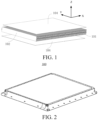
- the strength of the casing of the battery pack 100 is enhanced for resisting external impact by the battery pack 100.
- a bottom plate 1035 of a tray 103 is made of steel with higher strength or is made thicker.
- the tray 103 is configured as a multi-layer structure with cavities, and reinforcing ribs are arranged in the cavity structure.
- all the methods of enhancing the strength of the battery pack 100 lead to an increase in the weight of the entire battery pack 100 or a reduction in the space utilization of the battery pack 100, reducing the energy density of the battery pack 100.
- the honeycomb-like structure can bear the maximum force with the least material.
- the first reinforcing plate 104 and the cell array 101 deform in coordination. Therefore, the rigidity and strength of the battery pack 100 are greatly enhanced, thereby improving the mechanical safety and reliability.
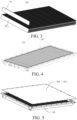
- the length of the cell 102 is greater than the height of the cell 102 and the height of the cell 102 is greater than the thickness of the cell 102, an area of the second surface defined by the length and the thickness is greater than an area of the third surface defined by the height and the thickness.
- the two first reinforcing plates 104 are adhered to the second surfaces of the cells 102.
- the two surfaces of all the cells 102 along the arrangement direction may be adhered to the first reinforcing plates 104, or, the two surfaces of only some of the cells 102 along the arrangement direction may be directly adhered to the first reinforcing plates 104.
- the two second surfaces or the two third surfaces of all the cells 102 in the cell array 101 are adhered to the two first reinforcing plates 104, to maximize the strength and rigidity of the battery pack 100.
- the shapes and areas of the two first reinforcing plates 104 are not particularly limited, as long as the two first reinforcing plates 104 have a certain strength, can connect the cell array 101 to form a unity, can enhance the structural strength of the cell array 101, and are not readily deformable.
- an area of the first reinforcing plate 104 may be different from an area of the surface of the cell array 101 to which the first reinforcing plate 104 is adhered.
- the area of the first reinforcing plate 104 may be smaller than the area of the surface of the cell array 101 to which the first reinforcing plate 104 is adhered.
- a number of layers of cell arrays 101 are arranged in the height direction (i.e., the Z direction) of the cell 102.
- a partition plate is arranged between two neighboring layers of cell arrays 101, and the partition plate is fixedly adhered to the cell arrays 101 on two sides of the partition plate.
- the second reinforcing plate 108 is fixedly adhered to the cells 102 arranged on two sides of the second reinforcing plate 108, to enhance the strength of the entire battery pack 100.
- the two first reinforcing plates 104 constitute the upper cover 105 and the bottom plate 1035 respectively.
- the bottom plate 1035 of the battery pack 100 may be designed as a sandwich composite material structure, which can bear the structural strength of the entire battery module.
- the bottom plate 1035 is designed as a composite board structure, and integrates a support strength function and a stone-chip resistant function for the bottom of the battery.
- the bottom plate 1035 may also integrate a support strength function and a liquid cooling function for the bottom of the battery.
- the foamed material layer includes a foamed polymer material, e.g., a polyurethane foam or phenolic foam material.
- the foamed material layer has a low thermal conductivity and can provide a good thermal insulation effect.
- the foamed material is of low density, and can reduce the weight of the battery pack 100 as compared with the case where the sealing cover is made of a steel plate or aluminum alloy.
- connection and fixing methods may be designed for the protection plate 111 and the side frame of the tray 103 of the battery pack 100, including riveting, automatic punch riveting, bolted connection, etc., which can be disassembled freely and facilitates repair, maintenance and inspection.
- the sealing groove may be provided on only the upper cover 105 or on only the side frame, or the upper cover 105 and the side frame are each provided with the sealing groove.
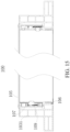
- the cell 102 when the side frame receives an external force, the cell 102 itself is a rigid member with great strength, and can transmit a force to the side frame through the supporting structure, to prevent plastic deformation of the side frame.
- the supporting structure includes a first support block 106, a lower surface of the first end of each of the cells 102 is supported by the first side frame 1031 through the first support block 106, and/ or a lower surface of the second end of the cell 102 is supported by the second side frame 1032 through the first support block 106.
- the lower surface of the first end of each of the cells 102 may be supported by the first side frame 1031, or may be supported by the support step on the first side frame 1031.
- the lower surface of the second end of the cell 102 may be supported by the second side frame 1032 through the first support block 106, or may be supported by the support step on the second side frame 1032.
- the supporting structure includes a second support block 107, the first end of each of the cells 102 facing the first side frame 1031 is fitted to the first side frame 1031 through the second support block 107, and/or, the second end of each of the cells 102 facing the second side frame 1032 is fitted to the second side frame 1032 through the second support block 107.
- Each of the cells 102 includes electrode terminals.
- the electrode terminals are respectively arranged at the first end and the second end of each of the cells 102.
- Holes 1071 are provided on the supporting structure.
- the electrode terminals of each of the cells 102 extend through the holes 1071 respectively and are electrically connected by a cell connector 110.
- the specific structure of the supporting structure is not limited, as long as the supporting structure is of a certain strength and is resistant to deformation under an external force.
- the material of the supporting structure includes one or more of polyether plastic (PPS), glass fiber, or polycarbonate.
- the side frame includes a third side frame 1033 and a fourth side frame arranged opposite to each other along the arrangement direction of the cells 102.
- the number of cells 102 are arranged side by side between the third side frame 1033 and the fourth side frame.
- the third side frame 1033 and the fourth side frame are respectively fixedly adhered to each of the cells 102 adjacent thereto.
- a reinforcing beam is arranged on the third side frame 1033 and/or the fourth side frame.
- the reinforcing beam may be in close contact with to the outer surface of each of the cells adjacent thereto or may be spaced from each of the cells adjacent thereto by a gap, to provide a limiting function for the expansion of the cell array 101.
- Step 3 Along the Y direction, the first side frame 1031 and the second side frame 1032 are arranged on the two end faces of the cell array 101.
- Step 4 The first side frame 1031 and the second side frame 1032 are connected to the third side frame 1033 and the fourth side frame by welding or fasteners (bolts, etc.).
- Step 5 The first reinforcing plates 104 are connected to the first side frame 1031, the second side frame 1032, the third side frame 1033, and the fourth side frame by a structural adhesive or fasteners.
- One of the first reinforcing plates 104 is the upper cover 105 of the battery pack 100.
- the other first reinforcing plate 104 is the bottom plate 1035 of the battery pack 100.
Landscapes
- Chemical & Material Sciences (AREA)
- Chemical Kinetics & Catalysis (AREA)
- Electrochemistry (AREA)
- General Chemical & Material Sciences (AREA)
- Engineering & Computer Science (AREA)
- Mechanical Engineering (AREA)
- Transportation (AREA)
- Aviation & Aerospace Engineering (AREA)
- Life Sciences & Earth Sciences (AREA)
- Sustainable Development (AREA)
- Sustainable Energy (AREA)
- Power Engineering (AREA)
- Combustion & Propulsion (AREA)
- Battery Mounting, Suspending (AREA)
- Arrangement Or Mounting Of Propulsion Units For Vehicles (AREA)
- Connection Of Batteries Or Terminals (AREA)
- Manufacturing & Machinery (AREA)
Claims (16)
- Batteriepack (100), umfassend:ein Zellenfeld bzw. -array (101), wobei das Zellenfeld eine Vielzahl von Zellen (102) umfasst; jede der Zellen ist mit einer Länge L, einer Dicke D und einer Höhe H zwischen der Länge L und der Dicke D definiert,wobei die Vielzahl von Zellen (102) entlang einer Dickenrichtung angeordnet sind und die Zellen durch einen strukturellen Klebstoff (1011) miteinander verklebt sind;zwei erste Verstärkungsplatten (104); wobei die zwei ersten Verstärkungsplatten einander gegenüberliegend angeordnet sind und jeweils an zwei Oberflächen des Zellenarrays (101) entlang einer Anordnungsrichtung der Zellen (102) haften und dazu konfiguriert sind, relative Positionen zwischen den Zellen zu erzwingen;dadurch gekennzeichnet, dass der Batteriesatz bzw. -pack eine Vielzahl von Lagen von Zellarrays (101) umfasst, die entlang einer Höhenrichtung (Z) der Zellen angeordnet sind, eine Trennplatte zwischen zwei benachbarten Lagen von Zellenarrays angeordnet ist und die Trennplatte an zwei Seiten der Trennplatte fest mit den Zellenarrays verklebt ist.
- Batteriepack gemäß Anspruch 1, wobei die beiden ersten Verstärkungsplatten (104) jeweils an zwei gegenüberliegenden Oberflächen der Zellen (102) entlang einer Höhenrichtung (Z) angeklebt sind.
- Batteriepack gemäß Anspruch 1 oder 2, wobei mindestens eine der Zellen (102) erfüllt: 600mm ≤ L ≤ 2500 mm, und 10 ≤ L/D ≤ 208.
- Batteriepack gemäß einem der Ansprüche 1 bis 3, wobei eine zweite Verstärkungsplatte (108) zwischen mindestens zwei benachbarten Zellen angeordnet ist; und die zweite Verstärkungsplatte (108) fest mit den Zellen (102) verbunden ist, die auf zwei Seiten der zweiten Verstärkungsplatte angeordnet sind.
- Batteriepack gemäß einem der Ansprüche 1 bis 4, wobei der Batteriepack ferner eine obere Abdeckung (105) und ein Tablett (103) umfasst, das Tablett eine Bodenplatte (1035) und einen die Bodenplatte umgebenden Seitenrahmen umfasst, die obere Abdeckung und das Tablett miteinander verbunden sind, um eine Zellenaufnahmekammer zu definieren, und das Zellenarray in der Zellenaufnahmekammer angeordnet ist.
- Batteriepack gemäß Anspruch 5, wobei die beiden ersten Verstärkungsplatten (104) die obere Abdeckung (105) bzw. die Bodenplatte (1035) bilden.
- Batteriepack gemäß Anspruch 6, wobei der Batteriepack ferner eine Schutzplatte (111) umfasst und die Schutzplatte auf einer Außenfläche der Bodenplatte (1035) angeordnet ist;wobei die Schutzplatte (111) vorzugsweise aus zwei Lagen Aluminiumplatten und einer Stahlplatte oder einer geschäumten Aluminiumplatte besteht, die zwischen den beiden Lagen Aluminiumplatten liegt;oder wobei die Schutzplatte (111) vorzugsweise zwei Faserverbundschichten und eine zwischen den beiden Faserverbundschichten angeordnete geschäumte Polymerschicht umfasst, und die Faserverbundschicht eine Glasfaserschicht oder eine Kohlenstofffaserschicht umfasst.
- Batteriepack gemäß Anspruch 5, wobei die Außenflächen der beiden ersten Verstärkungsplatten (104) jeweils an eine Innenfläche der oberen Abdeckung (105) und eine Innenfläche der Bodenplatte (1035) geklebt sind.
- Batteriepack gemäß einem der Ansprüche 6 bis 8, wobei mindestens eine der unteren Platte (1035) oder der oberen Abdeckung (105) zwei Schichten von Aluminiumplatten und eine Stahlplatte oder eine geschäumte Aluminiumplatte umfasst, die zwischen den beiden Schichten von Aluminiumplatten angeordnet ist;
oder mindestens eine der Bodenplatte (1035) und der oberen Abdeckung (105) zwei Faserverbundschichten und eine zwischen den beiden Faserverbundschichten liegende geschäumte Polymerschicht umfasst und die Faserverbundschicht eine Glasfaserschicht oder eine Kohlenstofffaserschicht umfasst. - Batteriepack gemäß einem der Ansprüche 6-9, wobei die obere Abdeckung (105) an einer dem Seitenrahmen entsprechenden Position mit einer Dichtungsnut versehen ist, in der Dichtungsnut eine Dichtungsschicht angeordnet ist und die obere Abdeckung und die Schale durch die Dichtungsschicht hermetisch verbunden sind.
- Batteriepack gemäß einem der Ansprüche 6-10, wobei jede der Zellen (102) ein erstes Ende und ein zweites Ende umfasst, die entlang einer Längsrichtung (Y) einander gegenüberliegend angeordnet sind, der Seitenrahmen einen ersten Seitenrahmen (1031) und einen zweiten Seitenrahmen (1032) umfasst, die entlang der Längsrichtung (Y) jeder der Zellen einander gegenüberliegend angeordnet sind, das erste Ende jeder der Zellen von dem ersten Seitenrahmen (1031) getragen wird und das zweite Ende jeder der Zellen von dem zweiten Seitenrahmen (1032) getragen wird.
- Batteriepack gemäß Anspruch 11, wobei eine erste Stützstufe (1034) an dem ersten Seitenrahmen (1031) angeordnet ist, eine zweite Stützstufe an dem zweiten Seitenrahmen angeordnet ist, das erste Ende jeder der Zellen von der ersten Stützstufe gestützt wird und das zweite Ende jeder der Zellen von der zweiten Stützstufe gestützt wird.
- Batteriepack gemäß Anspruch 12, wobei der Batteriesatz ferner eine Stützstruktur umfasst, wobei das erste Ende jeder der Zellen an dem ersten Seitenrahmen (1031) befestigt ist und von diesem durch die Stützstruktur gestützt wird und/oder das zweite Ende der Zelle an dem zweiten Seitenrahmen (1032) befestigt ist und von diesem durch die Stützstruktur gestützt wird.
- Batteriepack gemäß Anspruch 13, wobei jede der Zellen Elektrodenanschlüsse umfasst, die Elektrodenanschlüsse jeweils am ersten Ende und am zweiten Ende jeder der Zellen angeordnet sind, Löcher an der Trägerstruktur vorgesehen sind und die Elektrodenanschlüsse jeder der Zellen sich jeweils durch die Löcher erstrecken und durch einen Zellenverbinder elektrisch verbunden sind.
- Batteriepack gemäß Anspruch 14, wobei der Batteriepack ferner eine Isolationstrennplatte (109) umfasst, und die Isolationstrennplatte zwischen der Tragstruktur und einer Innenfläche des Seitenrahmens angeordnet ist.
- Elektrisches Fahrzeug, das den Batteriepack (100) gemäß einem der Ansprüche 1 - 15 umfasst.
Applications Claiming Priority (2)
| Application Number | Priority Date | Filing Date | Title |
|---|---|---|---|
| CN201911198132.9A CN112874285A (zh) | 2019-11-29 | 2019-11-29 | 电池包和电动车 |
| PCT/CN2020/122882 WO2021103867A1 (zh) | 2019-11-29 | 2020-10-22 | 电池包和电动车 |
Publications (3)
| Publication Number | Publication Date |
|---|---|
| EP4056408A1 EP4056408A1 (de) | 2022-09-14 |
| EP4056408A4 EP4056408A4 (de) | 2023-01-11 |
| EP4056408B1 true EP4056408B1 (de) | 2025-04-09 |
Family
ID=76038325
Family Applications (1)
| Application Number | Title | Priority Date | Filing Date |
|---|---|---|---|
| EP20893130.3A Active EP4056408B1 (de) | 2019-11-29 | 2020-10-22 | Batteriepack und elektrisches fahrzeug |
Country Status (9)
| Country | Link |
|---|---|
| US (1) | US20230023909A1 (de) |
| EP (1) | EP4056408B1 (de) |
| JP (2) | JP7644115B2 (de) |
| KR (1) | KR102839737B1 (de) |
| CN (3) | CN117799413A (de) |
| ES (1) | ES3023939T3 (de) |
| HU (1) | HUE071217T2 (de) |
| PL (1) | PL4056408T3 (de) |
| WO (1) | WO2021103867A1 (de) |
Families Citing this family (12)
| Publication number | Priority date | Publication date | Assignee | Title |
|---|---|---|---|---|
| US11996576B2 (en) * | 2020-07-03 | 2024-05-28 | Teijin Automotive Technologies, Inc. | Impact resistant frame of battery containment system |
| DE102021114483A1 (de) * | 2021-06-07 | 2022-12-08 | Audi Aktiengesellschaft | Verfahren zum Verbinden zweier Bauteile und Batteriemodul |
| DE102021115668A1 (de) * | 2021-06-17 | 2022-12-22 | Dr. Ing. H.C. F. Porsche Aktiengesellschaft | Batterie-Anordnung für ein Elektrofahrzeug |
| CN115692974B (zh) * | 2021-07-30 | 2025-02-11 | 比亚迪股份有限公司 | 电池包及其车辆 |
| CN217158406U (zh) * | 2022-01-12 | 2022-08-09 | 宁德时代新能源科技股份有限公司 | 一种电池包及用电装置 |
| JP7376856B1 (ja) * | 2022-06-17 | 2023-11-09 | Jfeスチール株式会社 | バッテリーケース |
| CN115411425A (zh) * | 2022-09-23 | 2022-11-29 | 广州小鹏汽车科技有限公司 | 电池包和车辆 |
| CN115863895B (zh) * | 2022-12-23 | 2026-01-30 | 浙江极氪智能科技有限公司 | 电池包和车辆 |
| JP7719113B2 (ja) * | 2023-03-07 | 2025-08-05 | プライムプラネットエナジー&ソリューションズ株式会社 | 電池パックおよびその製造方法 |
| CN116526045A (zh) * | 2023-05-26 | 2023-08-01 | 一汽解放汽车有限公司 | 电池包箱体及制备方法 |
| CN118231905A (zh) * | 2023-09-25 | 2024-06-21 | 比亚迪股份有限公司 | 电池包和用电装置 |
| KR102628969B1 (ko) * | 2023-09-27 | 2024-01-24 | 주식회사케이에스엠 | 전기차 배터리 케이스 제조방법 |
Citations (1)
| Publication number | Priority date | Publication date | Assignee | Title |
|---|---|---|---|---|
| JP2016066624A (ja) * | 2015-12-22 | 2016-04-28 | 三洋電機株式会社 | 電源装置 |
Family Cites Families (24)
| Publication number | Priority date | Publication date | Assignee | Title |
|---|---|---|---|---|
| JP4747539B2 (ja) * | 2004-09-13 | 2011-08-17 | マックス株式会社 | 電池パック |
| JP2009295381A (ja) * | 2008-06-04 | 2009-12-17 | Toshiba Corp | 電池セル及び電池パック |
| JP2012043758A (ja) * | 2010-08-23 | 2012-03-01 | Toshiba Corp | 組電池装置 |
| DE102011076575A1 (de) * | 2011-05-27 | 2012-11-29 | Bmw Ag | Energiespeichermodul aus mehreren insbesondere prismatischen Speicherzellen und Verfahren zur Herstellung eines Energiespeichermoduls sowie Verfahren zur Herstellung einer Endplatte für ein Energiespeichermodul |
| JP6010326B2 (ja) * | 2011-06-02 | 2016-10-19 | 株式会社東芝 | 二次電池装置、二次電池装置の製造方法 |
| JP5868676B2 (ja) | 2011-11-30 | 2016-02-24 | 三洋電機株式会社 | 電源装置及びこれを備える車両並びに蓄電装置 |
| JP6148555B2 (ja) * | 2013-07-16 | 2017-06-14 | 株式会社ジーエスエレテック | バスバーモジュール装置 |
| US9660244B2 (en) * | 2013-09-06 | 2017-05-23 | Johnson Controls Technology Company | System and method for establishing connections of a battery module |
| DE112015001861B4 (de) * | 2014-06-20 | 2024-02-08 | Robert Bosch Gmbh | Batteriemodul mit Zellenfixierung |
| US9911951B2 (en) * | 2014-09-30 | 2018-03-06 | Johnson Controls Technology Company | Battery module compressed cell assembly |
| EP3264492B1 (de) | 2015-02-27 | 2022-09-07 | LG Energy Solution, Ltd. | Batteriemodul |
| DE102015108611A1 (de) | 2015-06-01 | 2016-12-01 | Dr. Ing. H.C. F. Porsche Aktiengesellschaft | Fahrzeugkomponente |
| CN108140766B (zh) * | 2015-09-29 | 2021-03-30 | 株式会社杰士汤浅国际 | 蓄电装置及蓄电装置的制造方法 |
| WO2017163359A1 (ja) * | 2016-03-24 | 2017-09-28 | 株式会社 東芝 | 二次電池装置 |
| JP7020804B2 (ja) * | 2017-06-19 | 2022-02-16 | 本田技研工業株式会社 | バッテリパック |
| WO2019001357A1 (zh) * | 2017-06-30 | 2019-01-03 | 比亚迪股份有限公司 | 电池托盘、电池包总成以及具有它的车辆 |
| US11394086B2 (en) * | 2017-09-27 | 2022-07-19 | Kabushiki Kaisha Toshiba | Battery module and connection member |
| CN107994149A (zh) * | 2017-11-17 | 2018-05-04 | 康得复合材料有限责任公司 | 混合结构电池包 |
| CN108321314A (zh) * | 2018-01-18 | 2018-07-24 | 湖南三迅新能源科技有限公司 | 轻量化动力电池包 |
| CN208797084U (zh) * | 2018-11-19 | 2019-04-26 | 浙江爱特新能源汽车有限公司 | 一种动力电池包 |
| CN209169330U (zh) | 2018-11-26 | 2019-07-26 | 天津普兰能源科技有限公司 | 一种动力电池系统冷却板结构 |
| CN111384334B (zh) * | 2018-12-30 | 2024-09-13 | 宁德时代新能源科技股份有限公司 | 一种电池包 |
| KR102654288B1 (ko) * | 2019-01-09 | 2024-04-05 | 비와이디 컴퍼니 리미티드 | 배터리 팩, 차량, 및 에너지 저장 디바이스 |
| CN209561492U (zh) * | 2019-03-28 | 2019-10-29 | 宁德时代新能源科技股份有限公司 | 电池模组及电池包 |
-
2019
- 2019-11-29 CN CN202311408541.3A patent/CN117799413A/zh active Pending
- 2019-11-29 CN CN202311406256.8A patent/CN117533110A/zh active Pending
- 2019-11-29 CN CN201911198132.9A patent/CN112874285A/zh active Pending
-
2020
- 2020-10-22 WO PCT/CN2020/122882 patent/WO2021103867A1/zh not_active Ceased
- 2020-10-22 JP JP2022531447A patent/JP7644115B2/ja active Active
- 2020-10-22 US US17/780,892 patent/US20230023909A1/en active Pending
- 2020-10-22 EP EP20893130.3A patent/EP4056408B1/de active Active
- 2020-10-22 ES ES20893130T patent/ES3023939T3/es active Active
- 2020-10-22 HU HUE20893130A patent/HUE071217T2/hu unknown
- 2020-10-22 PL PL20893130.3T patent/PL4056408T3/pl unknown
- 2020-10-22 KR KR1020227017471A patent/KR102839737B1/ko active Active
-
2024
- 2024-04-05 JP JP2024061252A patent/JP2024095749A/ja active Pending
Patent Citations (1)
| Publication number | Priority date | Publication date | Assignee | Title |
|---|---|---|---|---|
| JP2016066624A (ja) * | 2015-12-22 | 2016-04-28 | 三洋電機株式会社 | 電源装置 |
Also Published As
| Publication number | Publication date |
|---|---|
| HUE071217T2 (hu) | 2025-08-28 |
| JP2024095749A (ja) | 2024-07-10 |
| US20230023909A1 (en) | 2023-01-26 |
| CN117799413A (zh) | 2024-04-02 |
| EP4056408A1 (de) | 2022-09-14 |
| CN112874285A (zh) | 2021-06-01 |
| ES3023939T3 (en) | 2025-06-03 |
| KR20220087529A (ko) | 2022-06-24 |
| EP4056408A4 (de) | 2023-01-11 |
| PL4056408T3 (pl) | 2025-08-04 |
| CN117533110A (zh) | 2024-02-09 |
| WO2021103867A1 (zh) | 2021-06-03 |
| JP2023503506A (ja) | 2023-01-30 |
| KR102839737B1 (ko) | 2025-07-30 |
| JP7644115B2 (ja) | 2025-03-11 |
Similar Documents
| Publication | Publication Date | Title |
|---|---|---|
| EP4056408B1 (de) | Batteriepack und elektrisches fahrzeug | |
| JP7577119B2 (ja) | 電池パック及び電気自動車 | |
| KR102953580B1 (ko) | 대형 배터리 모듈 및 이를 포함하는 배터리 팩 | |
| CN110993845B (zh) | 电池包及电动车 | |
| EP2624330B1 (de) | Batteriepack | |
| KR101150247B1 (ko) | 모듈의 구조 설계에 유연성을 가진 전지모듈 및 이를 포함하는 중대형 전지팩 | |
| US12034137B2 (en) | Mounting bracket for cell supervision circuit, battery pack, and vehicle | |
| KR20200112246A (ko) | 박판 타입의 모듈 하우징을 갖는 배터리 모듈과 이를 포함하는 배터리 팩 | |
| EP3930025B1 (de) | Batteriemodul, batteriepack und fahrzeug | |
| CN115863890B (zh) | 一种软包电池模组 | |
| CN224096889U (zh) | 电池箱体及电池箱 | |
| CN115377597A (zh) | 无框架的电池组及其制造方法 | |
| CN224036524U (zh) | 一种储能装置的外壳及储能装置 | |
| CN116097510B (zh) | 电池组、包括该电池组的车辆和能量存储系统 | |
| CN223451090U (zh) | 电池包及用电设备 | |
| US20260038934A1 (en) | Cell module, battery pack and method for assembling battery pack, vehicle | |
| EP4675785A1 (de) | Batteriegehäuse mit aussenrahmen | |
| CN118281456A (zh) | 电池包及用电装置 | |
| CN121769393A (zh) | 电池包及用电设备 | |
| KR20250138128A (ko) | 축전 장치 및 차량 | |
| CN120237353A (zh) | 电池包和用电设备 | |
| KR20250011444A (ko) | 전지 팩 및 이를 포함하는 디바이스 | |
| CN121367000A (zh) | 电池箱及电池包 | |
| CN117397100A (zh) | 具有改善的刚度的轻质电池模块壳体和包括其的电池组 | |
| CN115275481A (zh) | 一种电池系统 |
Legal Events
| Date | Code | Title | Description |
|---|---|---|---|
| STAA | Information on the status of an ep patent application or granted ep patent |
Free format text: STATUS: THE INTERNATIONAL PUBLICATION HAS BEEN MADE |
|
| PUAI | Public reference made under article 153(3) epc to a published international application that has entered the european phase |
Free format text: ORIGINAL CODE: 0009012 |
|
| STAA | Information on the status of an ep patent application or granted ep patent |
Free format text: STATUS: REQUEST FOR EXAMINATION WAS MADE |
|
| 17P | Request for examination filed |
Effective date: 20220609 |
|
| AK | Designated contracting states |
Kind code of ref document: A1 Designated state(s): AL AT BE BG CH CY CZ DE DK EE ES FI FR GB GR HR HU IE IS IT LI LT LU LV MC MK MT NL NO PL PT RO RS SE SI SK SM TR |
|
| A4 | Supplementary search report drawn up and despatched |
Effective date: 20221212 |
|
| RIC1 | Information provided on ipc code assigned before grant |
Ipc: B60K 1/04 20190101ALI20221206BHEP Ipc: H01M 10/625 20140101ALI20221206BHEP Ipc: B60L 50/64 20190101AFI20221206BHEP |
|
| DAV | Request for validation of the european patent (deleted) | ||
| DAX | Request for extension of the european patent (deleted) | ||
| GRAP | Despatch of communication of intention to grant a patent |
Free format text: ORIGINAL CODE: EPIDOSNIGR1 |
|
| STAA | Information on the status of an ep patent application or granted ep patent |
Free format text: STATUS: GRANT OF PATENT IS INTENDED |
|
| INTG | Intention to grant announced |
Effective date: 20241119 |
|
| GRAS | Grant fee paid |
Free format text: ORIGINAL CODE: EPIDOSNIGR3 |
|
| GRAA | (expected) grant |
Free format text: ORIGINAL CODE: 0009210 |
|
| STAA | Information on the status of an ep patent application or granted ep patent |
Free format text: STATUS: THE PATENT HAS BEEN GRANTED |
|
| AK | Designated contracting states |
Kind code of ref document: B1 Designated state(s): AL AT BE BG CH CY CZ DE DK EE ES FI FR GB GR HR HU IE IS IT LI LT LU LV MC MK MT NL NO PL PT RO RS SE SI SK SM TR |
|
| REG | Reference to a national code |
Ref country code: GB Ref legal event code: FG4D |
|
| REG | Reference to a national code |
Ref country code: CH Ref legal event code: EP |
|
| REG | Reference to a national code |
Ref country code: DE Ref legal event code: R096 Ref document number: 602020049322 Country of ref document: DE |
|
| REG | Reference to a national code |
Ref country code: IE Ref legal event code: FG4D |
|
| P01 | Opt-out of the competence of the unified patent court (upc) registered |
Free format text: CASE NUMBER: APP_17378/2025 Effective date: 20250409 |
|
| REG | Reference to a national code |
Ref country code: NL Ref legal event code: FP |
|
| REG | Reference to a national code |
Ref country code: ES Ref legal event code: FG2A Ref document number: 3023939 Country of ref document: ES Kind code of ref document: T3 Effective date: 20250603 |
|
| REG | Reference to a national code |
Ref country code: HU Ref legal event code: AG4A Ref document number: E071217 Country of ref document: HU |
|
| REG | Reference to a national code |
Ref country code: AT Ref legal event code: MK05 Ref document number: 1783258 Country of ref document: AT Kind code of ref document: T Effective date: 20250409 |
|
| PG25 | Lapsed in a contracting state [announced via postgrant information from national office to epo] |
Ref country code: FI Free format text: LAPSE BECAUSE OF FAILURE TO SUBMIT A TRANSLATION OF THE DESCRIPTION OR TO PAY THE FEE WITHIN THE PRESCRIBED TIME-LIMIT Effective date: 20250409 Ref country code: PT Free format text: LAPSE BECAUSE OF FAILURE TO SUBMIT A TRANSLATION OF THE DESCRIPTION OR TO PAY THE FEE WITHIN THE PRESCRIBED TIME-LIMIT Effective date: 20250811 |
|
| REG | Reference to a national code |
Ref country code: LT Ref legal event code: MG9D |
|
| PG25 | Lapsed in a contracting state [announced via postgrant information from national office to epo] |
Ref country code: GR Free format text: LAPSE BECAUSE OF FAILURE TO SUBMIT A TRANSLATION OF THE DESCRIPTION OR TO PAY THE FEE WITHIN THE PRESCRIBED TIME-LIMIT Effective date: 20250710 |
|
| PG25 | Lapsed in a contracting state [announced via postgrant information from national office to epo] |
Ref country code: BG Free format text: LAPSE BECAUSE OF FAILURE TO SUBMIT A TRANSLATION OF THE DESCRIPTION OR TO PAY THE FEE WITHIN THE PRESCRIBED TIME-LIMIT Effective date: 20250409 |
|
| PG25 | Lapsed in a contracting state [announced via postgrant information from national office to epo] |
Ref country code: HR Free format text: LAPSE BECAUSE OF FAILURE TO SUBMIT A TRANSLATION OF THE DESCRIPTION OR TO PAY THE FEE WITHIN THE PRESCRIBED TIME-LIMIT Effective date: 20250409 |
|
| PG25 | Lapsed in a contracting state [announced via postgrant information from national office to epo] |
Ref country code: AT Free format text: LAPSE BECAUSE OF FAILURE TO SUBMIT A TRANSLATION OF THE DESCRIPTION OR TO PAY THE FEE WITHIN THE PRESCRIBED TIME-LIMIT Effective date: 20250409 |
|
| PG25 | Lapsed in a contracting state [announced via postgrant information from national office to epo] |
Ref country code: RS Free format text: LAPSE BECAUSE OF FAILURE TO SUBMIT A TRANSLATION OF THE DESCRIPTION OR TO PAY THE FEE WITHIN THE PRESCRIBED TIME-LIMIT Effective date: 20250709 |
|
| PG25 | Lapsed in a contracting state [announced via postgrant information from national office to epo] |
Ref country code: IS Free format text: LAPSE BECAUSE OF FAILURE TO SUBMIT A TRANSLATION OF THE DESCRIPTION OR TO PAY THE FEE WITHIN THE PRESCRIBED TIME-LIMIT Effective date: 20250809 |
|
| PG25 | Lapsed in a contracting state [announced via postgrant information from national office to epo] |
Ref country code: LV Free format text: LAPSE BECAUSE OF FAILURE TO SUBMIT A TRANSLATION OF THE DESCRIPTION OR TO PAY THE FEE WITHIN THE PRESCRIBED TIME-LIMIT Effective date: 20250409 |
|
| PGFP | Annual fee paid to national office [announced via postgrant information from national office to epo] |
Ref country code: HU Payment date: 20251027 Year of fee payment: 6 |
|
| PGFP | Annual fee paid to national office [announced via postgrant information from national office to epo] |
Ref country code: NL Payment date: 20251021 Year of fee payment: 6 |
|
| PGFP | Annual fee paid to national office [announced via postgrant information from national office to epo] |
Ref country code: DE Payment date: 20251021 Year of fee payment: 6 |
|
| PGFP | Annual fee paid to national office [announced via postgrant information from national office to epo] |
Ref country code: GB Payment date: 20251022 Year of fee payment: 6 |
|
| PGFP | Annual fee paid to national office [announced via postgrant information from national office to epo] |
Ref country code: NO Payment date: 20251024 Year of fee payment: 6 |
|
| REG | Reference to a national code |
Ref country code: DE Ref legal event code: R097 Ref document number: 602020049322 Country of ref document: DE |
|
| PG25 | Lapsed in a contracting state [announced via postgrant information from national office to epo] |
Ref country code: DK Free format text: LAPSE BECAUSE OF FAILURE TO SUBMIT A TRANSLATION OF THE DESCRIPTION OR TO PAY THE FEE WITHIN THE PRESCRIBED TIME-LIMIT Effective date: 20250409 Ref country code: SM Free format text: LAPSE BECAUSE OF FAILURE TO SUBMIT A TRANSLATION OF THE DESCRIPTION OR TO PAY THE FEE WITHIN THE PRESCRIBED TIME-LIMIT Effective date: 20250409 |
|
| PGFP | Annual fee paid to national office [announced via postgrant information from national office to epo] |
Ref country code: IT Payment date: 20251024 Year of fee payment: 6 |
|
| PGFP | Annual fee paid to national office [announced via postgrant information from national office to epo] |
Ref country code: FR Payment date: 20251030 Year of fee payment: 6 |
|
| PG25 | Lapsed in a contracting state [announced via postgrant information from national office to epo] |
Ref country code: CZ Free format text: LAPSE BECAUSE OF FAILURE TO SUBMIT A TRANSLATION OF THE DESCRIPTION OR TO PAY THE FEE WITHIN THE PRESCRIBED TIME-LIMIT Effective date: 20250409 |
|
| PGFP | Annual fee paid to national office [announced via postgrant information from national office to epo] |
Ref country code: PL Payment date: 20251009 Year of fee payment: 6 |
|
| PG25 | Lapsed in a contracting state [announced via postgrant information from national office to epo] |
Ref country code: EE Free format text: LAPSE BECAUSE OF FAILURE TO SUBMIT A TRANSLATION OF THE DESCRIPTION OR TO PAY THE FEE WITHIN THE PRESCRIBED TIME-LIMIT Effective date: 20250409 |
|
| PG25 | Lapsed in a contracting state [announced via postgrant information from national office to epo] |
Ref country code: SK Free format text: LAPSE BECAUSE OF FAILURE TO SUBMIT A TRANSLATION OF THE DESCRIPTION OR TO PAY THE FEE WITHIN THE PRESCRIBED TIME-LIMIT Effective date: 20250409 |
|
| PGFP | Annual fee paid to national office [announced via postgrant information from national office to epo] |
Ref country code: ES Payment date: 20251216 Year of fee payment: 6 |
|
| PG25 | Lapsed in a contracting state [announced via postgrant information from national office to epo] |
Ref country code: RO Free format text: LAPSE BECAUSE OF FAILURE TO SUBMIT A TRANSLATION OF THE DESCRIPTION OR TO PAY THE FEE WITHIN THE PRESCRIBED TIME-LIMIT Effective date: 20250409 |
|
| PLBE | No opposition filed within time limit |
Free format text: ORIGINAL CODE: 0009261 |
|
| STAA | Information on the status of an ep patent application or granted ep patent |
Free format text: STATUS: NO OPPOSITION FILED WITHIN TIME LIMIT |
|
| REG | Reference to a national code |
Ref country code: CH Ref legal event code: L10 Free format text: ST27 STATUS EVENT CODE: U-0-0-L10-L00 (AS PROVIDED BY THE NATIONAL OFFICE) Effective date: 20260218 |
|
| 26N | No opposition filed |
Effective date: 20260112 |