EP4055281B1 - Arbeitszylinder - Google Patents
Arbeitszylinder Download PDFInfo
- Publication number
- EP4055281B1 EP4055281B1 EP20824438.4A EP20824438A EP4055281B1 EP 4055281 B1 EP4055281 B1 EP 4055281B1 EP 20824438 A EP20824438 A EP 20824438A EP 4055281 B1 EP4055281 B1 EP 4055281B1
- Authority
- EP
- European Patent Office
- Prior art keywords
- cylinder
- closure part
- cylinder tube
- piston
- working
- Prior art date
- Legal status (The legal status is an assumption and is not a legal conclusion. Google has not performed a legal analysis and makes no representation as to the accuracy of the status listed.)
- Active
Links
Images


Classifications
-
- F—MECHANICAL ENGINEERING; LIGHTING; HEATING; WEAPONS; BLASTING
- F15—FLUID-PRESSURE ACTUATORS; HYDRAULICS OR PNEUMATICS IN GENERAL
- F15B—SYSTEMS ACTING BY MEANS OF FLUIDS IN GENERAL; FLUID-PRESSURE ACTUATORS, e.g. SERVOMOTORS; DETAILS OF FLUID-PRESSURE SYSTEMS, NOT OTHERWISE PROVIDED FOR
- F15B15/00—Fluid-actuated devices for displacing a member from one position to another; Gearing associated therewith
- F15B15/08—Characterised by the construction of the motor unit
- F15B15/14—Characterised by the construction of the motor unit of the straight-cylinder type
- F15B15/1423—Component parts; Constructional details
- F15B15/1428—Cylinders
-
- B—PERFORMING OPERATIONS; TRANSPORTING
- B23—MACHINE TOOLS; METAL-WORKING NOT OTHERWISE PROVIDED FOR
- B23K—SOLDERING OR UNSOLDERING; WELDING; CLADDING OR PLATING BY SOLDERING OR WELDING; CUTTING BY APPLYING HEAT LOCALLY, e.g. FLAME CUTTING; WORKING BY LASER BEAM
- B23K26/00—Working by laser beam, e.g. welding, cutting or boring
- B23K26/20—Bonding
- B23K26/21—Bonding by welding
- B23K26/24—Seam welding
- B23K26/28—Seam welding of curved planar seams
- B23K26/282—Seam welding of curved planar seams of tube sections
-
- B—PERFORMING OPERATIONS; TRANSPORTING
- B23—MACHINE TOOLS; METAL-WORKING NOT OTHERWISE PROVIDED FOR
- B23K—SOLDERING OR UNSOLDERING; WELDING; CLADDING OR PLATING BY SOLDERING OR WELDING; CUTTING BY APPLYING HEAT LOCALLY, e.g. FLAME CUTTING; WORKING BY LASER BEAM
- B23K33/00—Specially-profiled edge portions of workpieces for making soldering or welding connections; Filling the seams formed thereby
- B23K33/004—Filling of continuous seams
- B23K33/006—Filling of continuous seams for cylindrical workpieces
-
- B—PERFORMING OPERATIONS; TRANSPORTING
- B23—MACHINE TOOLS; METAL-WORKING NOT OTHERWISE PROVIDED FOR
- B23K—SOLDERING OR UNSOLDERING; WELDING; CLADDING OR PLATING BY SOLDERING OR WELDING; CUTTING BY APPLYING HEAT LOCALLY, e.g. FLAME CUTTING; WORKING BY LASER BEAM
- B23K33/00—Specially-profiled edge portions of workpieces for making soldering or welding connections; Filling the seams formed thereby
- B23K33/004—Filling of continuous seams
- B23K33/008—Filling of continuous seams for automotive applications
-
- F—MECHANICAL ENGINEERING; LIGHTING; HEATING; WEAPONS; BLASTING
- F15—FLUID-PRESSURE ACTUATORS; HYDRAULICS OR PNEUMATICS IN GENERAL
- F15B—SYSTEMS ACTING BY MEANS OF FLUIDS IN GENERAL; FLUID-PRESSURE ACTUATORS, e.g. SERVOMOTORS; DETAILS OF FLUID-PRESSURE SYSTEMS, NOT OTHERWISE PROVIDED FOR
- F15B15/00—Fluid-actuated devices for displacing a member from one position to another; Gearing associated therewith
- F15B15/08—Characterised by the construction of the motor unit
- F15B15/14—Characterised by the construction of the motor unit of the straight-cylinder type
- F15B15/1423—Component parts; Constructional details
- F15B15/1438—Cylinder to end cap assemblies
-
- F—MECHANICAL ENGINEERING; LIGHTING; HEATING; WEAPONS; BLASTING
- F16—ENGINEERING ELEMENTS AND UNITS; GENERAL MEASURES FOR PRODUCING AND MAINTAINING EFFECTIVE FUNCTIONING OF MACHINES OR INSTALLATIONS; THERMAL INSULATION IN GENERAL
- F16J—PISTONS; CYLINDERS; SEALINGS
- F16J10/00—Engine or like cylinders; Features of hollow, e.g. cylindrical, bodies in general
- F16J10/02—Cylinders designed to receive moving pistons or plungers
-
- F—MECHANICAL ENGINEERING; LIGHTING; HEATING; WEAPONS; BLASTING
- F15—FLUID-PRESSURE ACTUATORS; HYDRAULICS OR PNEUMATICS IN GENERAL
- F15B—SYSTEMS ACTING BY MEANS OF FLUIDS IN GENERAL; FLUID-PRESSURE ACTUATORS, e.g. SERVOMOTORS; DETAILS OF FLUID-PRESSURE SYSTEMS, NOT OTHERWISE PROVIDED FOR
- F15B2215/00—Fluid-actuated devices for displacing a member from one position to another
- F15B2215/30—Constructional details thereof
Definitions
- the invention relates to a welded working cylinder with an increased load capacity.
- the closure parts are coupled to the cylinder tube in different ways according to the state of the art.
- a form-fitting coupling is often achieved by screwing the locking parts to the cylinder tube.
- the working cylinders produced in this way are therefore also known as screw cylinders.
- Screw cylinders as well as cylinders with screwing of only one locking part and MAG welding of the other locking part are provided in high quality according to the state of the art and have proven to be high-quality and reliable products.
- the object of the invention is to provide a working cylinder which has a particularly high quality and is material-saving, simple and thus cost-effective to manufacture.
- the working cylinder has a cylinder tube, a first and a second closure part and a piston unit as basic components.
- the first closure part and the second closure part are also referred to below as the closure parts.
- the working cylinder according to the invention can be in different designs.
- the working cylinder can be a differential working cylinder, a plunger cylinder, a synchronous cylinder, a telescopic cylinder, a pull cylinder or even a pneumatic Working cylinders. If the working cylinder is designed as a synchronous cylinder, it is also referred to below as a steering cylinder.
- Working cylinders in the sense of the present invention are also understood to include storage cylinders, gas spring cylinders and hydraulic shock absorbers.
- a working cylinder according to the invention can be designed to be double-acting or single-acting.
- a differential working cylinder for example, is a double-acting hydraulic working cylinder with two working chambers, with the piston's contact surfaces of different sizes in the two working chambers. With the same operating pressure, different forces act on the piston in the two actuation directions.
- the piston rod is guided by guide closure parts arranged on both sides, so that the piston's contact surfaces are of equal size and thus equal forces act in both actuation directions with the same operating pressure, so that synchronous cylinders are used in particular as steering cylinders.
- a plunger cylinder is a single-acting working cylinder in which the pressure medium displaces the piston as a volume body and thus causes its extension movement.
- the cylinder tube has a first cylinder tube end and a second cylinder tube end.
- the first closure part is arranged on the first cylinder tube end and the second closure part on the second cylinder tube end.
- Both cylinder tube ends are preferably manufactured the same.
- the two cylinder tube ends have beveled axial end faces, with the bevels having the same angle.
- the axial end faces therefore preferably have the same cross-sectional area.
- the first closure part is arranged on the first cylinder tube end.
- the first closure part is preferably a guide closure part.
- a guide closure part is understood to be a closure part which accommodates a piston unit in a sliding and sealing manner.
- the piston unit can consist of a piston and a piston rod, with the piston rod then being accommodated by the guide closure part.
- the piston unit is a volume-forming piston, also referred to as a plunger piston, which is accommodated by the guide closure part.
- the first closure part is designed in such a way that it has a contact surface which, when placed on the first cylinder tube end, rests against a corresponding further contact surface of the first cylinder tube end.
- These contact surfaces preferably completely surround the first closure part and the cylinder tube. This results in a continuous annular surface against which the first closure part rests on the first cylinder tube end.
- the annular surface is inclined at an angle so that in the geometric sense it is a truncated cone surface. For the sake of simplicity, this surface will be referred to below as simply a ring surface, regardless of its geometric design.
- the second closure part is arranged at the second cylinder tube end.
- the descriptions of the first closure part in its relationship to the first cylinder tube end apply accordingly to the second closure part in its relationship to the second cylinder tube end.
- the second closure part is designed analogously to the first closure part in terms of the contact surface.
- the second closure part is preferably a bottom closure part, which is then axially opposite the piston of the piston unit and axially delimits the at least one working space of the working cylinder according to the invention.
- the working cylinder according to the invention also has the piston unit.
- the piston unit can be formed from a piston and a piston rod - as is the case, for example, with a Differential working cylinder or a synchronous cylinder - or be formed solely by a piston - as is the case with a plunger cylinder, for example - or have other designs.
- the piston unit has a piston and a piston rod, the piston and the piston rod are in a fixed position relative to one another.
- the piston and the piston rod are firmly coupled to one another.
- the connection is preferably formed as a welded connection.
- the piston and piston rod can also be detachably coupled. In special cases, however, it is also possible for the piston unit to be formed in one piece and thus the piston and piston rod are sections of a monolithic component.
- the cylinder tube and the closure parts form a cylinder interior when assembled.
- their inner surface sections delimit the cylinder interior.
- the cylinder interior extends up to the respective laser ring weld seam.
- the piston unit forms at least one working chamber in the cylinder interior. This is delimited by the cylinder tube, a closure part and the piston unit.
- the piston unit is arranged to be axially displaceable, with the main longitudinal axis of the cylinder tube and the axial direction of movement of the piston unit coinciding.
- the piston unit preferably passes through the first closure part in a sliding and sealing manner, at least in sections.
- a pressure medium connection is assigned to the working chamber, via which the pressure medium can enter the working chamber or be led out of it, and the working chamber can thus be subjected to pressure.
- the pressure medium can be a hydraulic or pneumatic pressure medium.
- working cylinder according to the invention is, for example, in the form of a differential working cylinder, the following also applies.
- the piston of the piston unit is arranged in the cylinder interior and separates the cylinder interior into a piston bottom working chamber, hereinafter also referred to as the piston bottom chamber, and a piston rod working chamber.
- the piston bottom chamber is located between the piston and the second closure part, here designed as a bottom closure part.
- the piston rod working chamber is located on the side of the piston rod between the piston and the first closure part, here designed as a guide closure part.
- the at least one working chamber is therefore the piston rod working chamber.
- the piston bottom working chamber forms another working chamber.
- the piston is axially movable and is arranged in the cylinder interior in such a way that the main longitudinal axes of the piston and cylinder tube overlap.
- the pressure medium connections are arranged on the cylinder in such a way that the piston crown working chamber and the piston rod working chamber can be subjected to an operating pressure.
- the piston can also have various guide, sealing or piston rings.
- Various designs of a piston for a working cylinder are known as such from the prior art.
- the piston rod slides through the first closure part, here designed as a guide closure part.
- the piston rod is slidably mounted in the guide closure part, whereby the guide closure part is designed to prevent the pressure medium, hereinafter also referred to as fluid, from escaping. This is done, for example, by means of appropriate ring seals.
- the working cylinder according to the invention is characterized in particular in that both closure parts, for example in the case of a differential working cylinder both the guide closure part and the base closure part, are welded to the cylinder tube.
- the first closure part is connected to the cylinder tube by means of a first circumferential laser ring weld seam and the second closure part is connected to the cylinder tube by means of a second circumferential laser ring weld seam.
- the components connected to each other are also referred to collectively as the coupling partners below.
- the two closure parts are connected to the cylinder tube using a laser welding process.
- the laser ring weld seams are fusion welds without the addition of welding filler materials.
- Laser welding advantageously produces a very narrow, tapered weld seam.
- the acute angle spanned by the lateral flanks of the essentially V-shaped laser weld seam is preferably less than 15 degrees and particularly preferably less than 10 degrees.
- the two laser ring weld seams each form a fluid-tight sealing plane. This means that the first laser ring weld seam prevents pressure medium from passing through at the connection point between the cylinder tube and the first closure part and the second ring weld seam prevents pressure medium from passing through between the cylinder tube and the second closure part without the need for additional sealing means, such as a sealing ring.
- the cylinder tube and closure parts, and preferably also the piston unit, are each made of a metal alloy and particularly preferably of a steel alloy.
- the material composition of the individual components can differ slightly.
- the mass fractions of the components of the metal alloy of the cylinder differ from those of the closure parts by less than 10% by weight of the metal alloy of the closure parts.
- the closure parts and cylinder tube therefore have similar physical properties and can be welded together particularly well.
- the steel alloy used preferably has a carbon content of less than 0.5% by weight.
- the alloy components vanadium, chromium and manganese are included individually or in combination, preferably in a proportion of 0.01 to 2% by weight.
- the working cylinder is characterized in that at least one closure part has an axially opening, circumferential concave receiving contour into which the cylinder tube engages, wherein the receiving contour radially overlaps the cylinder tube and a ring weld seam center axis, with the main longitudinal axis, encloses a ring weld seam inclination angle alpha that is 110 to 160 degrees. This inclination exceeding 90 degrees is also referred to below as negatively inclined.
- the axially opening, circumferential concave receiving contour is provided by an annular groove in the relevant closure part, which has radial side walls.
- the side wall arranged radially on the outside is inclined and forms a conical shape.
- the concave receiving contour thus forms a radial overlap.
- the side wall arranged radially on the inside is preferably not inclined and preferably forms a cylindrical shape.
- the cross section of the receiving contour therefore preferably corresponds to a concave wedge.
- the cylinder tube is designed at the corresponding cylinder tube end to correspond to the receiving contour and for this purpose has an inclined annular surface, the angle of inclination of which corresponds to the angle of inclination of the outer radial side wall of the receiving contour.
- the cross section of the wall of the cylinder tube end therefore preferably corresponds to a wedge that fits into the receiving contour.
- the laser ring weld seam is arranged between the described inclined ring-shaped surfaces of the receiving contour and the cylinder tube.
- the angle of inclination of the laser ring weld seam corresponds to the angle of inclination of the two inclined ring-shaped surfaces.
- the welded working cylinder according to the invention has a number of significant advantages over working cylinders according to the state of the art.
- a first significant advantage is that the cylinder tube in particular requires little or no machining beyond cutting to length. In particular, no threads need to be cut or grooves turned.
- the machining of the cylinder tube is advantageously limited to the formation of the inclined front ring surface.
- Another advantage is a drastic saving in material and thus the conservation of raw material resources, because the cylinder tube only needs to have about half the tube wall thickness of a screwed differential working cylinder. Allowances, for example in the tube wall thickness to compensate for the material removal for a cut thread, can be eliminated.
- the elimination of machining of the cylinder tube and preferably also of the piston rod also significantly increases the quality.
- the axial concentricity is no longer impaired as a result of the elimination of force inputs through machining. Rather, the axial concentricity of the starting products for the cylinder tubes and possibly also the piston rods is completely retained.
- the working cylinder according to the invention therefore has a higher precision.
- the axial piston rod movement can also be provided without the problem of the piston rods buckling in the end stop, which is known from the state of the art. This also reduces the wear of the cylinder guides in the guide closure part.
- the elimination of machining of the cylinder tube and possibly also the piston rod also avoids reductions in load capacity due to notch effects.
- the concave receiving contour in conjunction with the ring weld seam inclination angle achieves three advantageous effects with the same means. Firstly, the radial overlap of the cylinder tube achieves a positive absorption of buckling forces caused by the working pressure of the pressure medium. The positive absorption of the radially acting buckling forces relieves the laser ring weld seam, so that the material-bonded force transmission at the laser ring weld seam is practically exclusively available for axial forces. Secondly, the inclination allows a ring weld seam depth to be achieved without additional measures that exceeds the cylinder tube wall thickness and thus enables a higher force transmission. Thirdly, an assembly advantage is achieved at the same time, since the cylinder tube and the relevant closure part center themselves automatically during an axial feed movement.
- Another advantage is the absolute tightness of the differential working cylinder at the connection points between the cylinder tube and the closure parts. Another advantage here is that the tightness can be achieved without the seals otherwise required by the state of the art. The possible elimination of these ageing-prone components not only results in cost savings, but also an improvement in quality and an increase in service life. In addition, contamination from ageing seals is eliminated.
- Another advantage is the increased operational reliability. There is no axial play between the cylinder tube and the locking parts when the load changes, as is the case with threads, or loosening, as is the case with threads. There are also advantageous savings due to the elimination of the locking elements that would otherwise be required. Ultimately, there is also no need to secure the actual locking elements, which is required for detachable connections. According to the state of the art, such securing is achieved by gluing the locking elements, for example. The elimination of gluing is associated with other important advantages. Firstly, the costs for the very expensive Screw locking adhesives. Secondly, there is no longer any need to clean the surfaces to make them adhesive for the screw locking adhesives, which, according to the current state of the art, often requires cleaning chemicals that are hazardous to health. This eliminates the need for special measures to ensure health protection and environmental protection. Thirdly, the problem that detachable connections secured with screw locking adhesives can also be at risk of loosening under impact loads is overcome.
- One aspect of the increased operational safety is the increased security against manipulation. Non-destructive interventions in the cylinder interior are impossible. Possible sources of injury in connection with improper opening or improper reassembly of a differential working cylinder by untrained personnel are eliminated.
- the laser welding process only results in a very localized heating of the material in the area of the laser ring weld seams. This means that components made of thermally sensitive materials, such as seals in particular, can still be welded within a few millimeters of the planned weld seam, which would be damaged by other welding processes.
- Another advantage is the reduction of thermal stresses in the coupling partners of the welded joint, since only a relatively small amount of energy per unit length (amount of energy related to the length of the weld seam) needs to be introduced by means of laser welding.
- a further advantage is that the course, the weld depth and the angle of the laser ring welds can be determined to a large extent by the movement, the energy per unit length and the angle of the laser beam relative to the working cylinder to be produced.
- the course and the angle can be specifically aligned, in particular by changing the position of the laser relative to the coupling partners.
- the working cylinder is a double-acting working cylinder and is designed as a differential working cylinder.
- the first closure part is designed as a guide closure part and the second closure part as a base closure part. Therefore, the first cylinder tube end is referred to here as the guide-side cylinder tube end and the second cylinder tube end as the base-side cylinder tube end.
- the first laser ring weld seam is thus arranged between the guide closure part and the guide-side cylinder tube end and the second laser ring weld seam is thus arranged between the base closure part and the base-side cylinder tube end.
- the piston unit in the differential working cylinder has a piston and a piston rod.
- the piston unit designed in this way reference is made to the description of the working cylinder above.
- the piston of the piston unit is arranged in the cylinder interior and thus divides the cylinder interior into a piston crown working chamber, also referred to as the piston crown chamber, and a piston rod working chamber, also referred to as the piston rod chamber.
- the effective area of the piston in the piston crown chamber is larger on the piston crown side of the piston than on the piston rod chamber side of the piston. With the same pressure of the pressure medium, a greater force acts on the piston on the piston crown chamber side than on the piston rod chamber side. A force acting on the piston is transferred from the cylinder interior to the outside by means of the piston rod, for which the piston rod slides through the guide closure part.
- the working cylinder is also a double-acting working cylinder; here, however, it is designed as a synchronous cylinder.
- the first closure part is designed as a guide closure part, as in a differential working cylinder.
- the second closure part is also designed as a further guide closure part.
- the guide closure part and the further guide closure part are also referred to below as the guide closure parts.
- the first laser ring weld seam is thus arranged between the guide closure part and the first cylinder tube end and the second laser ring weld seam is thus arranged between the further guide closure part and the second cylinder tube end.
- the piston unit has a piston and a piston rod.
- the piston is arranged in the cylinder interior and divides this into a first and a second piston rod working space.
- the piston rod projects axially beyond the piston on both sides and is guided out of the piston interior on both sides through the closure parts, which here are both present as guide closure parts. The piston rod thus slides through both guide closure parts.
- Both piston rod working chambers have the same cross-section and thus the piston has the same effective contact surface for the pressure medium on both sides.
- the force acting on the piston and the length of the working path covered by the piston are the same, regardless of whether a certain pressure flow of the pressure medium, equal in terms of pressure and volume, acts on the first or the second piston rod working chamber. Because of this in both Because the two actuation directions are the same, the synchronous cylinder is often used as a steering cylinder and is therefore also referred to as a steering cylinder.
- the working cylinder is designed as a plunger cylinder. This is a single-acting working cylinder.
- the first closure part is designed as a guide closure part and the second closure part as a base closure part.
- the first cylinder tube end is a guide-side cylinder tube end and the second cylinder tube end is a base-side cylinder tube end.
- the first laser ring weld seam is thus arranged between the guide closure part and the guide-side cylinder tube end and the second laser ring weld seam is thus arranged between the base closure part and the base-side cylinder tube end.
- the piston unit in the plunger cylinder is formed by a plunger piston.
- the plunger piston is arranged in the cylinder interior. Only one working chamber is formed in the cylinder interior.
- the plunger piston slides through the guide closure part.
- the plunger piston is axially displaced according to the volume of the pressure flow introduced and executes an extension movement.
- the retraction movement is caused by a force acting from the outside in the opposite direction.
- the working cylinder is characterized in that a first circumferential sealing ring is arranged in the cylinder interior between the first closure part and a cylinder tube inner wall of the cylinder tube at the first cylinder tube end axially spaced from the first laser ring weld seam, which forms a first pressure-separated ring section which is located between the first circumferential sealing ring and the first laser ring weld seam is arranged and/or that in the cylinder interior between the second closure part and a cylinder tube inner wall of the cylinder tube at its second cylinder tube end axially spaced from the second laser ring weld seam, a second circumferential sealing ring is arranged, which forms a second pressure-separated ring section which is arranged between the second circumferential sealing ring and the second laser ring weld seam.
- a circumferential sealing ring is arranged in front of at least one laser ring weld seam.
- a circumferential sealing ring is arranged in front of both laser ring weld seams.
- the circumferential sealing ring is also referred to below as an O-ring.
- the O-ring separates a ring section in front of the respective laser ring weld seam from the rest of the cylinder interior in a pressure-tight manner on the inside of the cylinder. It was surprisingly found that by forming a laser ring weld seam, the energy per unit length can be set so low that a thermally sensitive O-ring is not damaged even in the close vicinity of the laser ring weld seam.
- the close vicinity is understood to be an axial distance between the laser ring weld seam and the O-ring that is less than the inside diameter of a cylinder tube and particularly preferably no more than four times the thickness of a cylinder tube wall.
- the O-ring ensures that the ring section is separated from the working pressure of the pressure medium.
- the axial stress is based on the fact that the working pressure is applied to the base area of the respective closure part. of the pressure medium. This advantageously avoids multi-axial loading of the laser ring weld seam and multi-axial material stress there.
- the O-ring in front protects at least one working area or, depending on the type of working cylinder, both working areas with O-rings on both sides from contamination. Any emissions during laser welding or particles that could detach from the coupling partners in the area of the laser weld seam are held back in the respective ring section by the O-ring before they enter the working area.
- the laser ring weld seams have a laser ring weld seam depth which is in a ratio of 1.1 to 2.5 to a cylinder tube wall thickness.
- the depth of the laser ring weld seam is greater than the thickness of the cylinder tube wall. This means that the connection between the closure parts is particularly advantageously more stable, as the force transmission in the weld seam is distributed over a larger area and is therefore optimized.
- a further advantage is that the tube wall thickness of the cylinder tube can be further reduced for certain applications.
- the laser ring weld seam depth is also possible to make the laser ring weld seam depth greater than the cylinder tube wall thickness by inserting the laser ring weld seam deeper into the closure part than the cylinder tube is thick. This results in a deeper weld seam root.
- the laser ring weld seam depth is preferably at least 1.2 times the cylinder tube thickness. It was surprisingly found that the structural changes in the closure part brought about in this way increase the load-bearing capacity of the ring weld seams.
- Fig. 1 shows an embodiment in which the working cylinder is designed as a synchronous working cylinder.
- both closure parts 3, 4, i.e. the first closure part 3 and the second closure part 4 are designed as guide closure parts.
- the piston 5a is arranged in the axially central region of the piston rod 5b, which is guided by both closure parts 3, 4. Piston 5a and piston rod 5b together form the piston 5.
- the first cylinder tube end 6 is connected to the first closure part 3 by means of the negatively inclined first laser weld seam 9 and the second cylinder tube end is connected to the second closure part 4 by means of the negatively inclined second laser weld seam 10.
- the two closure parts 3, 4 each have a concave receiving contour 19 into which the obliquely formed annular surfaces of the respective cylinder tube ends 6, 7 are inserted and welded there by means of the laser welding process.
- Fig. 2 is the embodiment from Fig. 1 shown in more detail in an enlargement
- the second cylinder ear end 7 is already inserted into the wedge-shaped concave receiving contour 19 and welded to the second closure part 4 by means of the second circumferential laser ring weld seam 10.
- the ring weld center axis 13 and the main longitudinal axis 14 enclose the ring weld inclination angle alpha.
- the ring weld angle alpha has an angle between 110 and 160 degrees, in the exemplary embodiment of approximately 120 degrees.
- FIG. 3 The coupling partners are in accordance with Fig. 1 additionally shown in a schematic exploded view.
- Fig. 1 shows the first cylinder tube end 6 and the first closure part 3 with the wedge-shaped concave receiving contour 19 before joining.
- the concave receiving contour 19 is designed such that it can receive the first cylinder tube end 6 and forms a common contact surface with it, on which the first laser ring weld seam 9 is then arranged.
- Fig. 3 shows that the concave receiving contour 19 opens axially in the direction of the cylinder tube 2. Buckling forces acting radially from the inside on the cylinder tube 2 are thus positively absorbed by a radial overlap 20. This is the radially outer section of the concave receiving contour 19.
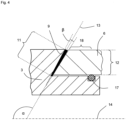
- a laser weld seam is shown enlarged.
- This first laser ring weld 9 has a ring weld depth 11 and a ring weld center axis 13. In this design, the ring weld depth 11 is greater than the cylinder tube wall thickness 12.
- the laser weld seam has a slight conicity. If two tangents are placed on the edge contour of the laser weld seam, they intersect and enclose a ring weld seam angle beta.
- the ring weld seam angle beta is preferably no more than 15 degrees and particularly preferably no more than 10 degrees.
- the ring weld seam center axis 13 is simultaneously the bisector of the ring weld seam angle beta and, together with the main longitudinal axis 14, encloses the ring weld seam inclination angle alpha. Furthermore, the ring weld seam center axis 13 runs along the contact surface of the first cylinder tube end 6 and the first closure part 3. In this design, the ring weld seam inclination angle alpha is 120 degrees.
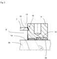
- FIG. 4 an embodiment with a circumferential sealing ring 17 (O-ring) positioned in front of the first laser ring weld seam 9, which separates the area in front of the first laser ring weld seam 9 from the pressure medium in a pressure-tight manner.
- This area is the pressure-separated ring section 18.
- the pressure-separated ring section 18 is located between the sealing ring 17 (O-ring) and the first laser ring weld seam 9.
- no radial forces act from the inside on the cylinder tube at its first cylinder tube end 6.
- the first laser ring weld seam 9 is therefore only loaded with an axial tensile stress.
- the sealing ring 17 (O-ring) in this design consists of an elastic polymer.
- the heat input during laser welding remains sufficiently low so as not to damage the sealing ring 17 (O-ring) despite the close proximity to the first laser ring weld seam 9.
- Fig. 4 combined with Fig. 3 It can be seen that due to the narrow design of the laser ring weld seams 9, 10 according to the invention, the material in the area of the radial overlap 20 is only thermally stressed to a small depth, so that the corresponding closure part only needs to have a small material thickness at the radial overlap 20.
Landscapes
- Engineering & Computer Science (AREA)
- Mechanical Engineering (AREA)
- Physics & Mathematics (AREA)
- General Engineering & Computer Science (AREA)
- Optics & Photonics (AREA)
- Fluid Mechanics (AREA)
- Plasma & Fusion (AREA)
- Chemical & Material Sciences (AREA)
- Combustion & Propulsion (AREA)
- Actuator (AREA)
- Pistons, Piston Rings, And Cylinders (AREA)
Applications Claiming Priority (2)
| Application Number | Priority Date | Filing Date | Title |
|---|---|---|---|
| DE202019004568.6U DE202019004568U1 (de) | 2019-11-08 | 2019-11-08 | Arbeitszylinder |
| PCT/DE2020/000270 WO2021089072A1 (de) | 2019-11-08 | 2020-11-06 | Arbeitszylinder |
Publications (2)
| Publication Number | Publication Date |
|---|---|
| EP4055281A1 EP4055281A1 (de) | 2022-09-14 |
| EP4055281B1 true EP4055281B1 (de) | 2025-01-08 |
Family
ID=73835294
Family Applications (1)
| Application Number | Title | Priority Date | Filing Date |
|---|---|---|---|
| EP20824438.4A Active EP4055281B1 (de) | 2019-11-08 | 2020-11-06 | Arbeitszylinder |
Country Status (8)
| Country | Link |
|---|---|
| US (1) | US20220397129A1 (da) |
| EP (1) | EP4055281B1 (da) |
| JP (1) | JP2023500364A (da) |
| CN (1) | CN114729654A (da) |
| DE (2) | DE202019004568U1 (da) |
| DK (1) | DK4055281T3 (da) |
| ES (1) | ES3020009T3 (da) |
| WO (1) | WO2021089072A1 (da) |
Families Citing this family (5)
| Publication number | Priority date | Publication date | Assignee | Title |
|---|---|---|---|---|
| DE102019007754A1 (de) * | 2019-11-08 | 2021-05-12 | Bümach Engineering International B.V. | Arbeitszylinder und Verfahren zu dessen Herstellung |
| DE202019004569U1 (de) * | 2019-11-08 | 2021-02-10 | Bümach Engineering International B.V. | Arbeitszylinder |
| DE102021001107A1 (de) * | 2021-03-02 | 2022-09-08 | Bümach Engineering International B.V. | Arbeitszylinder und Verfahren zu dessen Herstellung |
| JP7785106B2 (ja) | 2021-06-28 | 2025-12-12 | ビューマッハ エンジニアリング インターナショナル ベー.フェー. | 作動シリンダー及び当該作動シリンダーの製作方法 |
| CN117464209B (zh) * | 2023-11-17 | 2024-07-19 | 海目星激光科技集团股份有限公司 | 电池焊接装置和方法 |
Citations (2)
| Publication number | Priority date | Publication date | Assignee | Title |
|---|---|---|---|---|
| DE2511126C2 (de) * | 1975-03-14 | 1982-09-09 | Robert Bosch Gmbh, 7000 Stuttgart | Aus wenigstens zwei miteinander verschweißten Teilen bestehendes Gerät |
| DE202012008320U1 (de) * | 2012-08-31 | 2013-12-02 | Bümach Engineering International B.V. | Arbeitszylinder |
Family Cites Families (20)
| Publication number | Priority date | Publication date | Assignee | Title |
|---|---|---|---|---|
| US2997026A (en) * | 1959-10-12 | 1961-08-22 | Kingston Products Corp | Hydraulic actuator |
| US4324171A (en) * | 1978-06-16 | 1982-04-13 | Clark Equipment Company | Fluid device and method for making |
| DE4041992A1 (de) * | 1990-12-21 | 1992-07-02 | Mannesmann Ag | Verfahren zum herstellen eines fluidischen hubzylinders sowie eine kolben-zylinder-einheit |
| US6964221B2 (en) * | 2001-12-21 | 2005-11-15 | Cnh America Llc | Welded hydraulic actuator including a seal and method of manufacturing same |
| JP2003343515A (ja) * | 2002-05-24 | 2003-12-03 | Hitachi Constr Mach Co Ltd | シリンダ装置 |
| DE102006031365A1 (de) * | 2006-07-06 | 2008-01-17 | Franz Xaver Meiller Fahrzeug- Und Maschinenfabrik - Gmbh & Co Kg | Verfahren zur Herstellung eines Zylinderrohres für einen hydraulischen oder pneumatischen Zylinder und Bausatz zur Herstellung eines Zylinderrohres |
| DE102007004666A1 (de) * | 2007-01-25 | 2008-07-31 | Hahn Gasfedern Gmbh | Hydraulische oder pneumatische Einrichtung |
| DE112012007092T5 (de) * | 2012-12-20 | 2015-07-23 | Smc Kabushiki Kaisha | Fluiddruckzylinder |
| WO2015187673A1 (en) * | 2014-06-02 | 2015-12-10 | Afshari Thomas | Linear actuator assembly and system |
| WO2016083573A1 (en) * | 2014-11-28 | 2016-06-02 | General Electric Technology Gmbh | Fluid conduit element and method for producing the fluid conduit element |
| JP6521050B2 (ja) * | 2015-02-16 | 2019-05-29 | 株式会社タダノ | 液圧シリンダ、シリンダ装置、作業車両、及び液圧シリンダ製造方法 |
| CN105041760A (zh) * | 2015-06-08 | 2015-11-11 | 北京精密机电控制设备研究所 | 一种高压薄壁大直径挤压油箱 |
| DE102015212101B4 (de) * | 2015-06-30 | 2018-06-21 | Bayerische Motoren Werke Aktiengesellschaft | Hydrauliksteuerung für einen Aktuator in einem Fahrzeuggetriebe |
| US9903487B2 (en) * | 2016-06-22 | 2018-02-27 | Aladdin Engineering And Manufacturing, Inc. | Valve system for pneumatic cylinders |
| CN108035938A (zh) * | 2018-01-09 | 2018-05-15 | 嘉兴新维液压缸有限公司 | 一种推拉力相结合的油缸 |
| DE202019004569U1 (de) * | 2019-11-08 | 2021-02-10 | Bümach Engineering International B.V. | Arbeitszylinder |
| DE102019007754A1 (de) * | 2019-11-08 | 2021-05-12 | Bümach Engineering International B.V. | Arbeitszylinder und Verfahren zu dessen Herstellung |
| DE102021001107A1 (de) * | 2021-03-02 | 2022-09-08 | Bümach Engineering International B.V. | Arbeitszylinder und Verfahren zu dessen Herstellung |
| US11859598B2 (en) * | 2021-06-10 | 2024-01-02 | Hutchinson Technology Incorporated | Shape memory alloy actuators and methods thereof |
| JP7785106B2 (ja) * | 2021-06-28 | 2025-12-12 | ビューマッハ エンジニアリング インターナショナル ベー.フェー. | 作動シリンダー及び当該作動シリンダーの製作方法 |
-
2019
- 2019-11-08 DE DE202019004568.6U patent/DE202019004568U1/de active Active
-
2020
- 2020-11-06 ES ES20824438T patent/ES3020009T3/es active Active
- 2020-11-06 CN CN202080077688.7A patent/CN114729654A/zh active Pending
- 2020-11-06 WO PCT/DE2020/000270 patent/WO2021089072A1/de not_active Ceased
- 2020-11-06 DE DE112020005499.3T patent/DE112020005499A5/de active Pending
- 2020-11-06 DK DK20824438.4T patent/DK4055281T3/da active
- 2020-11-06 US US17/775,440 patent/US20220397129A1/en not_active Abandoned
- 2020-11-06 JP JP2022526396A patent/JP2023500364A/ja active Pending
- 2020-11-06 EP EP20824438.4A patent/EP4055281B1/de active Active
Patent Citations (2)
| Publication number | Priority date | Publication date | Assignee | Title |
|---|---|---|---|---|
| DE2511126C2 (de) * | 1975-03-14 | 1982-09-09 | Robert Bosch Gmbh, 7000 Stuttgart | Aus wenigstens zwei miteinander verschweißten Teilen bestehendes Gerät |
| DE202012008320U1 (de) * | 2012-08-31 | 2013-12-02 | Bümach Engineering International B.V. | Arbeitszylinder |
Also Published As
| Publication number | Publication date |
|---|---|
| DK4055281T3 (da) | 2025-03-24 |
| CN114729654A (zh) | 2022-07-08 |
| EP4055281A1 (de) | 2022-09-14 |
| WO2021089072A1 (de) | 2021-05-14 |
| DE202019004568U1 (de) | 2021-02-10 |
| US20220397129A1 (en) | 2022-12-15 |
| JP2023500364A (ja) | 2023-01-05 |
| ES3020009T3 (en) | 2025-05-21 |
| DE112020005499A5 (de) | 2022-08-25 |
Similar Documents
| Publication | Publication Date | Title |
|---|---|---|
| EP4055280B1 (de) | Arbeitszylinder | |
| EP4055281B1 (de) | Arbeitszylinder | |
| EP4055279A1 (de) | Arbeitszylinder und verfahren zu dessen herstellung | |
| EP3442784B1 (de) | Radialpresse | |
| DE112019003791T5 (de) | Fluiddruckgetriebene drucknietvorrichtung | |
| DE102013113895B4 (de) | Dehnspannfutter | |
| DE2644533C3 (de) | Starrer und im wesentlichen unveiformbarer Kolben insbesondere für Hochdruckverdichter sowie Verfahren zu seiner Herstellung | |
| DE3248148A1 (de) | Klemmhuelse | |
| EP1978263A2 (de) | Fluidbetätigter Linearantrieb | |
| DE3809461A1 (de) | Doppelhubzylinder | |
| WO2022184195A1 (de) | Arbeitszylinder und verfahren zu dessen herstellung | |
| EP3491254B1 (de) | Kolbeneinheit eines hydraulikzylinders | |
| EP4363727B1 (de) | Arbeitszylinder und verfahren zu dessen herstellung | |
| EP4055282B1 (de) | Kolbeneinheit für einen arbeitszylinder | |
| EP1494827A1 (de) | Vorrichtung zum plastischen verformen von werkst cken | |
| EP4093601B1 (de) | Radialpresse | |
| DE102004004109B4 (de) | Vorrichtung zur Verstellung des Matrizendurchmessers beim Ziehen, Durchdrücken und Fließpressen | |
| DE4220415A1 (de) | Zylinder, insbesondere für eine hydraulische Servolenkung | |
| EP2813712B1 (de) | Kolbeneinheit eines Plungerzylinders | |
| DE112013001201T5 (de) | Kolbenhaltevorrichtung und -verfahren | |
| DE2553035A1 (de) | Kernbohrwerkzeug | |
| DE2942917C2 (de) | Flanschverbindung an einem Druckspeicher für Hydraulikanlagen | |
| DE2138703A1 (de) | Zylinderkolbenanordnung, insbesondere einfach oder doppel wirkender druckluftzylinder | |
| DE102005006209A1 (de) | Doppel-Differentialzylinder und Verfahren zu seiner Montage | |
| DE2659080B2 (de) | Klemmkörper |
Legal Events
| Date | Code | Title | Description |
|---|---|---|---|
| STAA | Information on the status of an ep patent application or granted ep patent |
Free format text: STATUS: UNKNOWN |
|
| STAA | Information on the status of an ep patent application or granted ep patent |
Free format text: STATUS: THE INTERNATIONAL PUBLICATION HAS BEEN MADE |
|
| PUAI | Public reference made under article 153(3) epc to a published international application that has entered the european phase |
Free format text: ORIGINAL CODE: 0009012 |
|
| STAA | Information on the status of an ep patent application or granted ep patent |
Free format text: STATUS: REQUEST FOR EXAMINATION WAS MADE |
|
| 17P | Request for examination filed |
Effective date: 20220608 |
|
| AK | Designated contracting states |
Kind code of ref document: A1 Designated state(s): AL AT BE BG CH CY CZ DE DK EE ES FI FR GB GR HR HU IE IS IT LI LT LU LV MC MK MT NL NO PL PT RO RS SE SI SK SM TR |
|
| DAV | Request for validation of the european patent (deleted) | ||
| DAX | Request for extension of the european patent (deleted) | ||
| STAA | Information on the status of an ep patent application or granted ep patent |
Free format text: STATUS: EXAMINATION IS IN PROGRESS |
|
| 17Q | First examination report despatched |
Effective date: 20231124 |
|
| GRAP | Despatch of communication of intention to grant a patent |
Free format text: ORIGINAL CODE: EPIDOSNIGR1 |
|
| STAA | Information on the status of an ep patent application or granted ep patent |
Free format text: STATUS: GRANT OF PATENT IS INTENDED |
|
| INTG | Intention to grant announced |
Effective date: 20240917 |
|
| GRAS | Grant fee paid |
Free format text: ORIGINAL CODE: EPIDOSNIGR3 |
|
| GRAA | (expected) grant |
Free format text: ORIGINAL CODE: 0009210 |
|
| STAA | Information on the status of an ep patent application or granted ep patent |
Free format text: STATUS: THE PATENT HAS BEEN GRANTED |
|
| AK | Designated contracting states |
Kind code of ref document: B1 Designated state(s): AL AT BE BG CH CY CZ DE DK EE ES FI FR GB GR HR HU IE IS IT LI LT LU LV MC MK MT NL NO PL PT RO RS SE SI SK SM TR |
|
| REG | Reference to a national code |
Ref country code: GB Ref legal event code: FG4D Free format text: NOT ENGLISH |
|
| REG | Reference to a national code |
Ref country code: CH Ref legal event code: EP |
|
| REG | Reference to a national code |
Ref country code: DE Ref legal event code: R096 Ref document number: 502020010178 Country of ref document: DE |
|
| REG | Reference to a national code |
Ref country code: IE Ref legal event code: FG4D Free format text: LANGUAGE OF EP DOCUMENT: GERMAN |
|
| REG | Reference to a national code |
Ref country code: NL Ref legal event code: FP |
|
| REG | Reference to a national code |
Ref country code: DK Ref legal event code: T3 Effective date: 20250319 |
|
| REG | Reference to a national code |
Ref country code: SE Ref legal event code: TRGR |
|
| REG | Reference to a national code |
Ref country code: LT Ref legal event code: MG9D |
|
| REG | Reference to a national code |
Ref country code: ES Ref legal event code: FG2A Ref document number: 3020009 Country of ref document: ES Kind code of ref document: T3 Effective date: 20250521 |
|
| PG25 | Lapsed in a contracting state [announced via postgrant information from national office to epo] |
Ref country code: RS Free format text: LAPSE BECAUSE OF FAILURE TO SUBMIT A TRANSLATION OF THE DESCRIPTION OR TO PAY THE FEE WITHIN THE PRESCRIBED TIME-LIMIT Effective date: 20250408 |
|
| PG25 | Lapsed in a contracting state [announced via postgrant information from national office to epo] |
Ref country code: FI Free format text: LAPSE BECAUSE OF FAILURE TO SUBMIT A TRANSLATION OF THE DESCRIPTION OR TO PAY THE FEE WITHIN THE PRESCRIBED TIME-LIMIT Effective date: 20250108 |
|
| PG25 | Lapsed in a contracting state [announced via postgrant information from national office to epo] |
Ref country code: PL Free format text: LAPSE BECAUSE OF FAILURE TO SUBMIT A TRANSLATION OF THE DESCRIPTION OR TO PAY THE FEE WITHIN THE PRESCRIBED TIME-LIMIT Effective date: 20250108 |
|
| PG25 | Lapsed in a contracting state [announced via postgrant information from national office to epo] |
Ref country code: NO Free format text: LAPSE BECAUSE OF FAILURE TO SUBMIT A TRANSLATION OF THE DESCRIPTION OR TO PAY THE FEE WITHIN THE PRESCRIBED TIME-LIMIT Effective date: 20250408 Ref country code: IS Free format text: LAPSE BECAUSE OF FAILURE TO SUBMIT A TRANSLATION OF THE DESCRIPTION OR TO PAY THE FEE WITHIN THE PRESCRIBED TIME-LIMIT Effective date: 20250508 |
|
| PG25 | Lapsed in a contracting state [announced via postgrant information from national office to epo] |
Ref country code: HR Free format text: LAPSE BECAUSE OF FAILURE TO SUBMIT A TRANSLATION OF THE DESCRIPTION OR TO PAY THE FEE WITHIN THE PRESCRIBED TIME-LIMIT Effective date: 20250108 |
|
| PG25 | Lapsed in a contracting state [announced via postgrant information from national office to epo] |
Ref country code: PT Free format text: LAPSE BECAUSE OF FAILURE TO SUBMIT A TRANSLATION OF THE DESCRIPTION OR TO PAY THE FEE WITHIN THE PRESCRIBED TIME-LIMIT Effective date: 20250508 Ref country code: LV Free format text: LAPSE BECAUSE OF FAILURE TO SUBMIT A TRANSLATION OF THE DESCRIPTION OR TO PAY THE FEE WITHIN THE PRESCRIBED TIME-LIMIT Effective date: 20250108 |
|
| PG25 | Lapsed in a contracting state [announced via postgrant information from national office to epo] |
Ref country code: GR Free format text: LAPSE BECAUSE OF FAILURE TO SUBMIT A TRANSLATION OF THE DESCRIPTION OR TO PAY THE FEE WITHIN THE PRESCRIBED TIME-LIMIT Effective date: 20250409 Ref country code: BG Free format text: LAPSE BECAUSE OF FAILURE TO SUBMIT A TRANSLATION OF THE DESCRIPTION OR TO PAY THE FEE WITHIN THE PRESCRIBED TIME-LIMIT Effective date: 20250108 |
|
| PG25 | Lapsed in a contracting state [announced via postgrant information from national office to epo] |
Ref country code: SM Free format text: LAPSE BECAUSE OF FAILURE TO SUBMIT A TRANSLATION OF THE DESCRIPTION OR TO PAY THE FEE WITHIN THE PRESCRIBED TIME-LIMIT Effective date: 20250108 |
|
| REG | Reference to a national code |
Ref country code: DE Ref legal event code: R097 Ref document number: 502020010178 Country of ref document: DE |
|
| PGFP | Annual fee paid to national office [announced via postgrant information from national office to epo] |
Ref country code: DK Payment date: 20250924 Year of fee payment: 6 |
|
| PGFP | Annual fee paid to national office [announced via postgrant information from national office to epo] |
Ref country code: SE Payment date: 20250916 Year of fee payment: 6 |
|
| REG | Reference to a national code |
Ref country code: DE Ref legal event code: R082 Ref document number: 502020010178 Country of ref document: DE Representative=s name: WEIHRAUCH, FRANK, DR., DE |
|
| PG25 | Lapsed in a contracting state [announced via postgrant information from national office to epo] |
Ref country code: EE Free format text: LAPSE BECAUSE OF FAILURE TO SUBMIT A TRANSLATION OF THE DESCRIPTION OR TO PAY THE FEE WITHIN THE PRESCRIBED TIME-LIMIT Effective date: 20250108 |
|
| PG25 | Lapsed in a contracting state [announced via postgrant information from national office to epo] |
Ref country code: RO Free format text: LAPSE BECAUSE OF FAILURE TO SUBMIT A TRANSLATION OF THE DESCRIPTION OR TO PAY THE FEE WITHIN THE PRESCRIBED TIME-LIMIT Effective date: 20250108 |
|
| PG25 | Lapsed in a contracting state [announced via postgrant information from national office to epo] |
Ref country code: SK Free format text: LAPSE BECAUSE OF FAILURE TO SUBMIT A TRANSLATION OF THE DESCRIPTION OR TO PAY THE FEE WITHIN THE PRESCRIBED TIME-LIMIT Effective date: 20250108 |
|
| PLBE | No opposition filed within time limit |
Free format text: ORIGINAL CODE: 0009261 |
|
| STAA | Information on the status of an ep patent application or granted ep patent |
Free format text: STATUS: NO OPPOSITION FILED WITHIN TIME LIMIT |
|
| REG | Reference to a national code |
Ref country code: CH Ref legal event code: L10 Free format text: ST27 STATUS EVENT CODE: U-0-0-L10-L00 (AS PROVIDED BY THE NATIONAL OFFICE) Effective date: 20251119 |
|
| REG | Reference to a national code |
Ref country code: CH Ref legal event code: U11 Free format text: ST27 STATUS EVENT CODE: U-0-0-U10-U11 (AS PROVIDED BY THE NATIONAL OFFICE) Effective date: 20251201 |
|
| PGFP | Annual fee paid to national office [announced via postgrant information from national office to epo] |
Ref country code: NL Payment date: 20251121 Year of fee payment: 6 |
|
| 26N | No opposition filed |
Effective date: 20251009 |
|
| PGFP | Annual fee paid to national office [announced via postgrant information from national office to epo] |
Ref country code: DE Payment date: 20251130 Year of fee payment: 6 |
|
| PGFP | Annual fee paid to national office [announced via postgrant information from national office to epo] |
Ref country code: GB Payment date: 20251021 Year of fee payment: 6 |
|
| PGFP | Annual fee paid to national office [announced via postgrant information from national office to epo] |
Ref country code: AT Payment date: 20251104 Year of fee payment: 6 |
|
| PGFP | Annual fee paid to national office [announced via postgrant information from national office to epo] |
Ref country code: FR Payment date: 20251110 Year of fee payment: 6 |
|
| PGFP | Annual fee paid to national office [announced via postgrant information from national office to epo] |
Ref country code: BE Payment date: 20251015 Year of fee payment: 6 |
|
| PGFP | Annual fee paid to national office [announced via postgrant information from national office to epo] |
Ref country code: CH Payment date: 20251201 Year of fee payment: 6 |
|
| PGFP | Annual fee paid to national office [announced via postgrant information from national office to epo] |
Ref country code: CZ Payment date: 20251014 Year of fee payment: 6 |
|
| PGFP | Annual fee paid to national office [announced via postgrant information from national office to epo] |
Ref country code: ES Payment date: 20251201 Year of fee payment: 6 |