EP4054347B1 - Verfahren und vorrichtung zur herstellung eines karbonisierten getränks - Google Patents
Verfahren und vorrichtung zur herstellung eines karbonisierten getränks Download PDFInfo
- Publication number
- EP4054347B1 EP4054347B1 EP20803122.9A EP20803122A EP4054347B1 EP 4054347 B1 EP4054347 B1 EP 4054347B1 EP 20803122 A EP20803122 A EP 20803122A EP 4054347 B1 EP4054347 B1 EP 4054347B1
- Authority
- EP
- European Patent Office
- Prior art keywords
- water
- static mixer
- compensator
- carbon dioxide
- mixer
- Prior art date
- Legal status (The legal status is an assumption and is not a legal conclusion. Google has not performed a legal analysis and makes no representation as to the accuracy of the status listed.)
- Active
Links
- 238000000034 method Methods 0.000 title claims description 10
- 235000014171 carbonated beverage Nutrition 0.000 title description 3
- XLYOFNOQVPJJNP-UHFFFAOYSA-N water Substances O XLYOFNOQVPJJNP-UHFFFAOYSA-N 0.000 claims description 69
- CURLTUGMZLYLDI-UHFFFAOYSA-N Carbon dioxide Chemical compound O=C=O CURLTUGMZLYLDI-UHFFFAOYSA-N 0.000 claims description 66
- 239000001569 carbon dioxide Substances 0.000 claims description 33
- 229910002092 carbon dioxide Inorganic materials 0.000 claims description 33
- 230000003068 static effect Effects 0.000 claims description 31
- 235000008504 concentrate Nutrition 0.000 claims description 27
- 235000013361 beverage Nutrition 0.000 claims description 6
- 230000007423 decrease Effects 0.000 claims description 4
- 238000007373 indentation Methods 0.000 claims description 3
- 230000001105 regulatory effect Effects 0.000 claims description 2
- 238000011144 upstream manufacturing Methods 0.000 claims description 2
- 238000002360 preparation method Methods 0.000 claims 3
- 238000009434 installation Methods 0.000 description 14
- 239000012141 concentrate Substances 0.000 description 10
- 238000004519 manufacturing process Methods 0.000 description 6
- 239000002775 capsule Substances 0.000 description 3
- 238000001816 cooling Methods 0.000 description 3
- 239000007788 liquid Substances 0.000 description 3
- 238000002347 injection Methods 0.000 description 2
- 239000007924 injection Substances 0.000 description 2
- 238000004806 packaging method and process Methods 0.000 description 2
- 238000010924 continuous production Methods 0.000 description 1
- 239000000498 cooling water Substances 0.000 description 1
- 239000011521 glass Substances 0.000 description 1
- 239000000463 material Substances 0.000 description 1
- 239000002184 metal Substances 0.000 description 1
- 239000000843 powder Substances 0.000 description 1
- 238000007789 sealing Methods 0.000 description 1
- 239000008399 tap water Substances 0.000 description 1
- 235000020679 tap water Nutrition 0.000 description 1
Images


Classifications
-
- B—PERFORMING OPERATIONS; TRANSPORTING
- B01—PHYSICAL OR CHEMICAL PROCESSES OR APPARATUS IN GENERAL
- B01F—MIXING, e.g. DISSOLVING, EMULSIFYING OR DISPERSING
- B01F23/00—Mixing according to the phases to be mixed, e.g. dispersing or emulsifying
- B01F23/20—Mixing gases with liquids
- B01F23/23—Mixing gases with liquids by introducing gases into liquid media, e.g. for producing aerated liquids
- B01F23/236—Mixing gases with liquids by introducing gases into liquid media, e.g. for producing aerated liquids specially adapted for aerating or carbonating beverages
- B01F23/2363—Mixing systems, i.e. flow charts or diagrams; Arrangements, e.g. comprising controlling means
-
- A—HUMAN NECESSITIES
- A23—FOODS OR FOODSTUFFS; TREATMENT THEREOF, NOT COVERED BY OTHER CLASSES
- A23L—FOODS, FOODSTUFFS, OR NON-ALCOHOLIC BEVERAGES, NOT COVERED BY SUBCLASSES A21D OR A23B-A23J; THEIR PREPARATION OR TREATMENT, e.g. COOKING, MODIFICATION OF NUTRITIVE QUALITIES, PHYSICAL TREATMENT; PRESERVATION OF FOODS OR FOODSTUFFS, IN GENERAL
- A23L2/00—Non-alcoholic beverages; Dry compositions or concentrates therefor; Their preparation
- A23L2/52—Adding ingredients
- A23L2/54—Mixing with gases
-
- B—PERFORMING OPERATIONS; TRANSPORTING
- B01—PHYSICAL OR CHEMICAL PROCESSES OR APPARATUS IN GENERAL
- B01F—MIXING, e.g. DISSOLVING, EMULSIFYING OR DISPERSING
- B01F23/00—Mixing according to the phases to be mixed, e.g. dispersing or emulsifying
- B01F23/20—Mixing gases with liquids
- B01F23/23—Mixing gases with liquids by introducing gases into liquid media, e.g. for producing aerated liquids
- B01F23/236—Mixing gases with liquids by introducing gases into liquid media, e.g. for producing aerated liquids specially adapted for aerating or carbonating beverages
-
- B—PERFORMING OPERATIONS; TRANSPORTING
- B01—PHYSICAL OR CHEMICAL PROCESSES OR APPARATUS IN GENERAL
- B01F—MIXING, e.g. DISSOLVING, EMULSIFYING OR DISPERSING
- B01F23/00—Mixing according to the phases to be mixed, e.g. dispersing or emulsifying
- B01F23/20—Mixing gases with liquids
- B01F23/23—Mixing gases with liquids by introducing gases into liquid media, e.g. for producing aerated liquids
- B01F23/237—Mixing gases with liquids by introducing gases into liquid media, e.g. for producing aerated liquids characterised by the physical or chemical properties of gases or vapours introduced in the liquid media
- B01F23/2376—Mixing gases with liquids by introducing gases into liquid media, e.g. for producing aerated liquids characterised by the physical or chemical properties of gases or vapours introduced in the liquid media characterised by the gas being introduced
- B01F23/23762—Carbon dioxide
- B01F23/237621—Carbon dioxide in beverages
-
- B—PERFORMING OPERATIONS; TRANSPORTING
- B01—PHYSICAL OR CHEMICAL PROCESSES OR APPARATUS IN GENERAL
- B01F—MIXING, e.g. DISSOLVING, EMULSIFYING OR DISPERSING
- B01F23/00—Mixing according to the phases to be mixed, e.g. dispersing or emulsifying
- B01F23/40—Mixing liquids with liquids; Emulsifying
- B01F23/48—Mixing liquids with liquids; Emulsifying characterised by the nature of the liquids
- B01F23/483—Mixing liquids with liquids; Emulsifying characterised by the nature of the liquids using water for diluting a liquid ingredient, obtaining a predetermined concentration or making an aqueous solution of a concentrate
-
- B—PERFORMING OPERATIONS; TRANSPORTING
- B01—PHYSICAL OR CHEMICAL PROCESSES OR APPARATUS IN GENERAL
- B01F—MIXING, e.g. DISSOLVING, EMULSIFYING OR DISPERSING
- B01F25/00—Flow mixers; Mixers for falling materials, e.g. solid particles
- B01F25/40—Static mixers
- B01F25/42—Static mixers in which the mixing is affected by moving the components jointly in changing directions, e.g. in tubes provided with baffles or obstructions
- B01F25/43—Mixing tubes, e.g. wherein the material is moved in a radial or partly reversed direction
- B01F25/431—Straight mixing tubes with baffles or obstructions that do not cause substantial pressure drop; Baffles therefor
- B01F25/4314—Straight mixing tubes with baffles or obstructions that do not cause substantial pressure drop; Baffles therefor with helical baffles
- B01F25/43141—Straight mixing tubes with baffles or obstructions that do not cause substantial pressure drop; Baffles therefor with helical baffles composed of consecutive sections of helical formed elements
-
- B—PERFORMING OPERATIONS; TRANSPORTING
- B01—PHYSICAL OR CHEMICAL PROCESSES OR APPARATUS IN GENERAL
- B01F—MIXING, e.g. DISSOLVING, EMULSIFYING OR DISPERSING
- B01F25/00—Flow mixers; Mixers for falling materials, e.g. solid particles
- B01F25/40—Static mixers
- B01F25/44—Mixers in which the components are pressed through slits
- B01F25/441—Mixers in which the components are pressed through slits characterised by the configuration of the surfaces forming the slits
- B01F25/4413—Mixers in which the components are pressed through slits characterised by the configuration of the surfaces forming the slits the slits being formed between opposed conical or cylindrical surfaces
-
- B—PERFORMING OPERATIONS; TRANSPORTING
- B01—PHYSICAL OR CHEMICAL PROCESSES OR APPARATUS IN GENERAL
- B01F—MIXING, e.g. DISSOLVING, EMULSIFYING OR DISPERSING
- B01F25/00—Flow mixers; Mixers for falling materials, e.g. solid particles
- B01F25/40—Static mixers
- B01F25/44—Mixers in which the components are pressed through slits
- B01F25/442—Mixers in which the components are pressed through slits characterised by the relative position of the surfaces during operation
- B01F25/4423—Mixers in which the components are pressed through slits characterised by the relative position of the surfaces during operation the surfaces being part of a valve construction, formed by opposed members in contact, e.g. automatic positioning caused by spring pressure
-
- B—PERFORMING OPERATIONS; TRANSPORTING
- B01—PHYSICAL OR CHEMICAL PROCESSES OR APPARATUS IN GENERAL
- B01F—MIXING, e.g. DISSOLVING, EMULSIFYING OR DISPERSING
- B01F35/00—Accessories for mixers; Auxiliary operations or auxiliary devices; Parts or details of general application
- B01F35/80—Forming a predetermined ratio of the substances to be mixed
- B01F35/83—Forming a predetermined ratio of the substances to be mixed by controlling the ratio of two or more flows, e.g. using flow sensing or flow controlling devices
-
- B—PERFORMING OPERATIONS; TRANSPORTING
- B67—OPENING, CLOSING OR CLEANING BOTTLES, JARS OR SIMILAR CONTAINERS; LIQUID HANDLING
- B67D—DISPENSING, DELIVERING OR TRANSFERRING LIQUIDS, NOT OTHERWISE PROVIDED FOR
- B67D1/00—Apparatus or devices for dispensing beverages on draught
- B67D1/0042—Details of specific parts of the dispensers
- B67D1/0057—Carbonators
- B67D1/0058—In-line carbonators
-
- A—HUMAN NECESSITIES
- A23—FOODS OR FOODSTUFFS; TREATMENT THEREOF, NOT COVERED BY OTHER CLASSES
- A23V—INDEXING SCHEME RELATING TO FOODS, FOODSTUFFS OR NON-ALCOHOLIC BEVERAGES AND LACTIC OR PROPIONIC ACID BACTERIA USED IN FOODSTUFFS OR FOOD PREPARATION
- A23V2002/00—Food compositions, function of food ingredients or processes for food or foodstuffs
-
- A—HUMAN NECESSITIES
- A23—FOODS OR FOODSTUFFS; TREATMENT THEREOF, NOT COVERED BY OTHER CLASSES
- A23V—INDEXING SCHEME RELATING TO FOODS, FOODSTUFFS OR NON-ALCOHOLIC BEVERAGES AND LACTIC OR PROPIONIC ACID BACTERIA USED IN FOODSTUFFS OR FOOD PREPARATION
- A23V2300/00—Processes
- A23V2300/04—Aeration
-
- B—PERFORMING OPERATIONS; TRANSPORTING
- B01—PHYSICAL OR CHEMICAL PROCESSES OR APPARATUS IN GENERAL
- B01F—MIXING, e.g. DISSOLVING, EMULSIFYING OR DISPERSING
- B01F2215/00—Auxiliary or complementary information in relation with mixing
- B01F2215/04—Technical information in relation with mixing
- B01F2215/0413—Numerical information
- B01F2215/0436—Operational information
- B01F2215/045—Numerical flow-rate values
-
- B—PERFORMING OPERATIONS; TRANSPORTING
- B01—PHYSICAL OR CHEMICAL PROCESSES OR APPARATUS IN GENERAL
- B01F—MIXING, e.g. DISSOLVING, EMULSIFYING OR DISPERSING
- B01F2215/00—Auxiliary or complementary information in relation with mixing
- B01F2215/04—Technical information in relation with mixing
- B01F2215/0413—Numerical information
- B01F2215/0436—Operational information
- B01F2215/0468—Numerical pressure values
-
- B—PERFORMING OPERATIONS; TRANSPORTING
- B01—PHYSICAL OR CHEMICAL PROCESSES OR APPARATUS IN GENERAL
- B01F—MIXING, e.g. DISSOLVING, EMULSIFYING OR DISPERSING
- B01F2215/00—Auxiliary or complementary information in relation with mixing
- B01F2215/04—Technical information in relation with mixing
- B01F2215/0413—Numerical information
- B01F2215/0436—Operational information
- B01F2215/0472—Numerical temperature values
Definitions
- the invention relates to a method for producing a beverage in portions, in which a beverage concentrate portion is mixed with a water portion, the water portion being mixed with carbon dioxide strictly in accordance with claim 1 before mixing with the beverage concentrate. Furthermore, the present invention relates to a device for producing a drink in portions, in which a drink concentrate portion is mixed with a water portion, the water portion being mixed with carbon dioxide in a static mixer strictly in accordance with claim 6 before being mixed with the drink concentrate.
- the problem is solved with a process for producing a drink in portions, in which a drink concentrate portion is mixed with a water portion, the water portion being mixed with carbon dioxide before being mixed with the drink concentrate, in which the addition of carbon dioxide is carried out at an overpressure of at least 7 bar , preferably > 8 bar, particularly preferably at 9-11 bar.
- the present invention relates to a method for producing a drink in portions.
- drink concentrate portions are used, especially in a single or Reusable packaging is provided, the liquid or powder content of which is mixed with a portion of water, in particular a portion of tap water, which forms the finished drink.
- the water is mixed with carbon dioxide bubbles and the carbon dioxide is at least partially, preferably completely dissolved in the water.
- the carbon dioxide is preferably added to the water in portions and particularly preferably immediately before the carbonated water is mixed with the beverage concentrate.
- the addition of carbon dioxide to the water is preferably carried out in a continuous process in which water and carbon dioxide are added in a coordinated ratio.
- the carbon dioxide dissolves in the water at least largely, preferably completely.
- the water portion is preferably taken from a water tank and brought to the desired pressure using a pump.
- the carbon dioxide is preferably taken from a pressure bottle.
- the mixing of water and carbon dioxide is preferably carried out in portions but particularly preferably continuously, while the water flows, in particular is removed from a water tank for beverage production.
- the water is made available at a temperature of 0 - 4 ° C before mixing with carbon dioxide. According to a further preferred embodiment, the water is made available at a temperature of 4 - 10 ° C before mixing with carbon dioxide.
- the water is preferably cooled after being removed from the water tank, in particular cooled in a heat exchanger. The water is preferably cooled in portions.
- the carbon dioxide is preferably mixed into the water, at least essentially in bubble form.
- the carbon dioxide is dissolved in the water by mixing the carbon dioxide with the water in a static mixer, wherein according to another preferred embodiment, a dynamic mixer, ie a mixer with a rotor, is used alternatively or additionally.
- the flow speed in the static mixer is particularly preferably 3 - 8 m/s.
- the static mixer Before and after the production of the carbonated water portion, there is preferably a reduced pressure in the static mixer compared to operating conditions, preferably ambient pressure. As soon as the volume of water required to produce a beverage portion has been carbonated, the pump is switched off and the pressure in the static mixer is reduced, preferably to ambient pressure.
- the ratio of the amount of water to the amount of carbon dioxide is regulated.
- the volume flow and/or the flow velocity of the water is measured and the carbon dioxide volume flow is metered in accordingly.
- the object is also achieved with a device for producing a drink in portions, in which a drink concentrate portion is mixed with a water portion, the water portion being mixed with carbon dioxide in a static mixer before being mixed with the drink concentrate, and the static mixer being formed from several mixer stages.
- This subject of the present invention relates to a device for producing a drink in portions.
- a portion of water is mixed with a portion of a beverage concentrate, resulting in the beverage to be produced.
- the water is carbonated before it is mixed with the beverage concentrate.
- carbon dioxide is added to the water and mixed together in a static mixer in such a way that the added carbon dioxide dissolves at least largely in the water.
- the static mixer has several mixer stages, which are separated from one another, for example, by a wall with a recess.
- the water and carbon dioxide flow through the recess.
- the static mixer is preferably manufactured in one piece, preferably as a plastic injection molded part.
- the output of a downstream mixer stage forms a nozzle for the upstream mixer stage adjacent to it.
- the flow cross section of the static mixer decreases in the direction of flow, preferably in steps.
- two to four, preferably four static mixers, in particular identical static mixers, are connected in series.
- a compensator is provided downstream of the static mixer.
- the carbonated water flows through the compensator before being used to make a drink.
- the compensator can be used to reduce pressure in which little gas outgasses from the liquid.
- the compensator is preferably a substantially rotationally symmetrical component.
- the compensator preferably has an inlet and an outlet and the outlet is provided offset from the longitudinal central axis of the compensator.
- the outlet is provided offset from the longitudinal center axis, preferably eccentric to the longitudinal center axis of the compensator. This means that the center of the compensator is free and can be used for other purposes, for example to regulate pressure loss.
- the compensator preferably has a housing in which there is a built-in element, with a gap, the width of which is preferably adjustable, between the housing and the built-in element.
- the carbonated water flows through this gap from the inlet of the compensator to its outlet.
- the gap width is preferably constant over its entire length.
- the installation element preferably has a conical and a cylindrical section, with projections and/or indentations being provided on the cylindrical section, the length of which in the longitudinal direction is a maximum of 40% of the length of the cylindrical part.
- ribs are provided on the conical part of the installation element, which are preferably elastic.
- the ribs can consist of the same or a different material as the built-in element and/or be a form of the conical part of the built-in element.
- indentations are provided in the installation element, which accommodate the ribs in a form-fitting and/or non-positive manner.
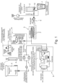
- FIG. 1 shows the device for producing a drink 1.
- a drink concentrate which in the present case is provided as portion 2 in a disposable or reusable packaging, for example a plastic or metal cartridge, is mixed with a portion of water, for example 200 ml, mixed and then collected in a container.
- the water is made available in the water tank 3 and brought to the desired pressure of at least 7 bar by means of the pump 8, here two pumps connected in parallel or redundant.
- the flow rate that runs from the tank 3 into the container 1 is preferably monitored by means of a flow meter 10, which preferably also controls the pumps so that the desired volume of water is delivered.
- the pump is preferably switched on and then switched off again after the desired amount of water has been drawn.
- the water is preferably cooled, in particular before it is carbonated.
- water cooling is provided, which has a heat exchanger with a cooling water circuit.
- the CO 2 is preferably added to the water after cooling.
- the CO 2 is taken from a carbon dioxide supply 4, here a pressure bottle, and metered into the water, in particular in bubble form, using a CO 2 metering device 11.
- the CO 2 dosage is preferably carried out depending on the flow rate of water, which is determined by means of the flow meter 10.
- a mixer here a static mixer 5, is provided downstream of the CO 2 metering, which here is designed in two stages, each stage preferably having several mixer stages.
- the static mixer is preferably designed in such a way that the flow cross-section decreases in the direction of flow after each mixer stage.
- the two stages of the static mixer are preferably designed to be uniform.
- the static mixer is preferably a plastic part, in particular a plastic injection molded part.
- the CO 2 metered in in bubble form is dissolved, preferably in particular completely, in the water.
- a compensator is provided downstream of the static mixer, with which the pressure in the static mixer can be adjusted. According to the invention, this pressure should be at least 7 bar.
- the residence time of the water between the static mixer and the chamber 12 in which the carbonated water is mixed with the beverage concentrate portion is as short as possible.
- the finished drink flows out of the beverage concentrate portion capsule 2 and is collected in a container, here a glass.
- the beverage concentrate is preferably pressed out of the portion capsule 2 using air.
- the Figures 2 to 4 each show a representation of the compensator 6.
- the compensator 6 is provided downstream of the mixer 5.
- the compensator 6 has a housing 13 in which an installation element 14 is provided.
- the installation element 14 and the housing 13 are essentially rotationally symmetrical.
- the compensator 6 has a longitudinal central axis 26.
- In the housing 13 there is an inlet 19 through which the carbonated water flows in and then flows in the direction of the outlet 20 in a gap 15, which is located between the housing 13 and the installation element 14.
- the outlet 20 is provided offset from the longitudinal central axis 26.
- the outlet is provided in an insert 18 which is inserted into the housing 13.
- an adjusting means 17 is provided, which can be adjusted in the directions shown by the double arrow by means of the screw 21, which in the present case has a thread located in the insert 18. This allows the width of the gap 15 and thus the pressure loss that occurs in the compensator to be adjusted.
- a spring element 16 is provided between the adjusting means 17 and the installation element 14, which attempts to bias the installation element in the direction of the inlet and/or in the direction of the smallest possible gap.
- Sealing elements 25 can be provided both on the adjustment means 17 and on the insert 18, which prevent the water that flows towards the outlet from leaving the compensator in undesired places.
- the installation element 14 here has a conical part 23 and a cylindrical part 24.
- ribs 22 are preferably provided in particular on the conical part, which space the installation element from the housing and thereby create channels 15 provide through which the liquid can flow from the inlet towards the outlet as shown by the arrows.
Landscapes
- Chemical & Material Sciences (AREA)
- Chemical Kinetics & Catalysis (AREA)
- Dispersion Chemistry (AREA)
- Health & Medical Sciences (AREA)
- Nutrition Science (AREA)
- Life Sciences & Earth Sciences (AREA)
- Engineering & Computer Science (AREA)
- Food Science & Technology (AREA)
- Polymers & Plastics (AREA)
- Devices For Dispensing Beverages (AREA)
- Non-Alcoholic Beverages (AREA)
Description
- Die Erfindung betrifft ein Verfahren zur portionsweisen Herstellung eines Getränks, bei dem eine Getränkekonzentratportion mit einer Wasserportion gemischt wird, wobei die Wasserportion vor der Vermischung mit dem Getränkekonzentrat mit Kohlenstoffdioxid strikt gemäß Anspruch 1 versetzt wird. Des Weiteren betrifft die vorliegende Erfindung eine Vorrichtung zur portionsweisen Herstellung eines Getränks, bei dem eine Getränkekonzentratportion mit einer Wasserportion gemischt wird, wobei die Wasserportion vor der Vermischung mit dem Getränkekonzentrat mit Kohlenstoffdioxid in einem Statikmischer strikt gemäß Anspruch 6 versetzt wird.
- Der Bedarf an portionsweiser Herstellung von karbonisierten Getränken unter Verwendung einer Getränkekonzentratportion steigt ständig. In der Vergangenheit war jedoch oftmals die Karbonisierung nicht ausreichend, so dass das portionsweise mit einer Getränkekonzentratportion hergestellte Getränk nicht wie das in Flaschen oder Fässern abgefüllte Original schmeckte. So lehrt
DE102011001252 ein Verfahren und eine Vorrichtung zur portionsweisen Herstellung von wasserbasierten karbonisierten Postmix-Getränken zum direkten Verbrauch, wobei Wasser karbonisiert und anschließend mit einem portionsweise abgepackten vorkarbonisierten Getränkekonzentrat vermischt wird. - Es war deshalb die Aufgabe ein Verfahren und eine Vorrichtung Verfahren zur portionsweisen Herstellung eines Getränks, bei dem eine Getränkekonzentratportion mit einer Wasserportion gemischt wird, zur Verfügung zu stellen, das/die die Nachteile des Standes der Technik nicht aufweist.
- Gelöst wird die Aufgabe mit einem Verfahren zur portionsweisen Herstellung eines Getränks, bei dem eine Getränkekonzentratportion mit einer Wasserportion gemischt wird, wobei die Wasserportion vor der Vermischung mit dem Getränkekonzentrat mit Kohlenstoffdioxid versetzt wird, bei dem die Versetzung mit Kohlenstoffdioxid bei einem Überdruck von mindestens 7 Bar, vorzugsweise > 8 Bar, besonders bevorzugt bei 9- 11 Bar erfolgt.
- Die zu diesem Gegenstand der vorliegenden Erfindung gemachte Offenbarung gilt auch für die anderen Gegenstände der vorliegenden Erfindung. Merkmale, die im Zusammenhang mit diesem Gegenstand der vorliegenden Erfindung offenbar wurden, können auch in andere Gegenstände aufgenommen werden.
- Die vorliegende Erfindung betrifft ein Verfahren zur portionsweisen Herstellung eines Getränks. Dafür wird Getränkekonzentratportion, insbesondere in einer Ein- oder Mehrwegverpackung zur Verfügung gestellt, deren flüssiger oder pulverförmiger Inhalt mit einer Wasserportion, insbesondere einer Leitungswasserportion vermischt wird, die das fertige Getränk bilden. Vor der Vermischung mit dem Getränkekonzentrat mit Kohlenstoffdioxid versetzt das Wasser mit Kohlenstoffdioxidblasen versetzt und das Kohlendioxid zumindest teilweise, vorzugsweise vollständig in dem Wasser gelöst. Der Versatz des Wassers mit dem Kohlenstoffdioxid erfolgt vorzugsweise ebenfalls portionsweise und besonders bevorzugt unmittelbar bevor das karbonisierte Wasser mit dem Getränkekonzentrat gemischt wird.
- Der Versatz des Wassers mit dem Kohlenstoffdioxid erfolgt vorzugsweise ein einem kontinuierlichen Prozess, bei dem Wasser und Kohlenstoffdioxid in einem aufeinander abgestimmten Verhältnis versetzt werden.
- Erfindungsgemäß herrscht während des Versatzes des Wassers mit Kohlenstoffdioxid ein Überdruck von mindestens 7 Bar, vorzugsweise > 8 Bar, besonders bevorzugt bei 9- 11 Bar. Dadurch löst sich das Kohlenstoffdioxid in dem Wasser zumindest weitestgehend, vorzugsweise vollständig.
- Die Wasserportion wird vorzugsweise einem Wassertank entnommen und mit einer Pumpe auf den gewünschten Druck gebracht. Der Kohlenstoffdioxid wird vorzugsweise einer Druckflasche entnommen.
- Die Vermischung von Wasser und Kohlenstoffdioxid erfolgt vorzugsweise portionsweise aber besonders bevorzugt kontinuierlich, während das Wasser fließt, insbesondere zur Getränkeherstellung einem Wassertank entnommen wird.
- Gemäß einer bevorzugten Ausführungsform wird das Wasser vor dem Mischen mit Kohlenstoffdioxid bei einer Temperatur von 0 - 4°C zur Verfügung gestellt. Gemäß einer weiteren bevorzugten Ausführungsform wird das Wasser vor dem Mischen mit Kohlenstoffdioxid bei einer Temperatur von 4 - 10 °C zur Verfügung gestellt. Dafür wird das Wasser nach der Entnahme aus dem Wassertank vorzugsweise gekühlt, insbesondere in einem Wärmetauscher gekühlt. Die Kühlung des Wassers erfolgt vorzugsweise portionsweise.
- Der Kohlenstoffdioxid wird dem Wasser vorzugsweise, zumindest im Wesentlichen blasenförmig, zugemischt. Die Lösung des Kohlenstoffdioxids in dem Wasser durch Mischung des Kohlenstoffdioxids mit dem Wasser erfolgt in einem Statikmischer,
wobei gemäß einer anderen bevorzugten Ausführungsform alternativ oder zusätzlich ein dynamischer Mischer, d.h. ein Mischer mit einem Rotor, eingesetzt wird. Besonders bevorzugt beträgt die Strömungsgeschwindigkeit in dem Statikmischer 3 - 8 m/s. - In dem Statikmischer herrscht vor und nach der Herstellung der karbonisierten Wasserportion vorzugsweise ein im Vergleich zu Betriebsbedingungen verminderter Druck, vorzugsweise Umgebungsdruck. Sobald das für die Herstellung einer Getränkeportion benötigte Wasservolumen karbonisiert worden ist, wird die Pumpe abgeschaltet und der Druck in dem Statikmischer reduziert sich, vorzugsweise auf Umgebungsdruck.
- Gemäß einer bevorzugten Ausführungsform wird das Verhältnis von Wasser- zu Kohlenstoffdioxid-Menge geregelt. Besonders bevorzugt wird dafür der Volumenstrom und/oder die Strömungsgeschwindgkeit des Wassers gemessen und der Kohlenstoffdioxid-Volumenstrom entsprechend zudosiert.
- Die Aufgabe wird außerdem mit einer Vorrichtung zur portionsweisen Herstellung eines Getränks gelöst, bei dem eine Getränkekonzentratportion mit einer Wasserportion gemischt wird, wobei die Wasserportion vor der Vermischung mit dem Getränkekonzentrat mit Kohlenstoffdioxid in einem Statikmischer versetzt wird und der Statikmischer aus mehreren Mischerstufen gebildet ist.
- Die zu diesem Gegenstand der vorliegenden Erfindung gemachte Offenbarung gilt auch für die anderen Gegenstände der vorliegenden Erfindung. Merkmale, die im Zusammenhang mit diesem Gegenstand der vorliegenden Erfindung offenbar wurden, können auch in andere Gegenstände aufgenommen werden.
- Dieser Gegenstand der vorliegenden Erfindung betrifft eine Vorrichtung zur portionsweisen Herstellung eines Getränks. Eine Portion Wasser wird mit einer Portion eines Getränkekonzentrats gemischt und daraus resultiert das herzustellende Getränk. Vor der Vermischung mit dem Getränkekonzentrat wird das Wasser karbonisiert. Dafür wird dem Wasser Kohlenstoffdioxid zugesetzt und in einem Statikmischer so miteinander Vermischt, dass das sich zudosierte Kohlenstoffdioxid zumindest weitestgehend in dem Wasser löst.
- Erfindungsgemäß weist der Statikmischer mehrere Mischerstufen auf, die beispielsweise durch eine Wand mit einer Ausnehmung voneinander getrennt sind. Durch die Ausnehmung strömen das Wasser und das Kohlenstoffdioxid.
- Vorzugsweise ist der Statikmischer einstückig gefertigt, vorzugsweise als Kunststoffspritzgussteil.
- Vorzugsweise bildet der Ausgang einer stromabwärtigen Mischerstufe eine Düse für die daran benachbarte stromaufwärtige Mischerstufe.
- Vorzugsweise vermindert sich der Durchströmungsquerschnitt des Statikmischers in Strömungsrichtung, vorzugsweise stufenförmig.
- Vorzugsweise sind zwei bis vier, bevorzugt vier Statikmischer, insbesondere baugleiche Statikmischer in Reihe geschaltet.
- Stromabwärts von dem Statikmischer ist ein Kompensator vorgesehen. Das karbonisierte Wasser strömt durch den Kompensator bevor es für die Herstellung eines Getränks eingesetzt wird. Der Kompensator kann zur Druckminderung eingesetzt werden, bei der wenig Gas aus der Flüssigkeit ausgast.
- Der Kompensator ist vorzugsweise ein im Wesentlichen rotationssymmetrisches Bauteil Vorzugsweise weist der Kompensator einen Einlass und einen Auslass auf und der Auslass versetzt zur Längsmittelachse des Kompensators vorgesehen ist. Gemäß dieser bevorzugten Ausführungsform der vorliegenden Erfindung ist der Auslass versetzt zur Längsmittelachse, vorzugsweise exzentrisch zur Längsmittelachse des Kompensators vorgesehen. Dadurch ist das Zentrum des Kompensators frei und kann für andere Zwecke, beispielsweise zur Druckverlustregulierung eingesetzt werden.
- Vorzugsweise weist der Kompensator ein Gehäuse auf, in dem sich ein Einbauelement befindet, wobei sich zwischen dem Gehäuse und dem Einbauelement ein Spalt, dessen Breite vorzugsweise einstellbar ist, befindet. Durch diesen Spalt strömt das Karbonisierte Wasser von dem Einlass des Kompensators zu dessen Auslass. Die Spaltbreite ist vorzugsweise über dessen gesamte Länge konstant.
- Vorzugsweise weist das Einbauelement einen konischen und einen zylindrischen Abschnitt auf, wobei an dem zylindrischen Abschnitt Vorsprünge und/oder Einbuchtungen vorgesehen sind, deren Länge in Längsrichtung maximal 40% der Länge des zylindrischen Teils beträgt. Gemäß einer bevorzugten Ausführungsform sind an dem konischen Teil des Einbauelementes Rippen vorgesehen, die vorzugsweise elastisch sind. Die Rippen können aus dem gleichen oder einem anderen Material als das Einbauelement bestehen und/oder eine Ausprägung des konischen Teils des Einbauelementes sein. Vorzugsweise sind in dem Einbauelement Einbuchtungen vorgesehen, die die Rippen from- und/oder kraftschlüssig aufnehmen.
- Im Folgenden wird die Erfindung anhand der
Figuren 1 - 4 erläutert. - Figur 1
- zeigt schematisch das erfindugsgemäße Verfahren.
- Figuren 2 - 4
- zeigen jeweils eine Darstellung des Kompensators.
- Diese Erläuterungen sind lediglich beispielhaft und schränken den allgemeinen Erfindungsgedanken nicht ein. Diese Erläuterungen gelten für alle Gegenstände der vorliegenden Erfindung gleichermaßen.
-
Figur 1 zeigt die Vorrichtung zur Herstellung eines Getränkes 1. Für die Herstellung des Getränks wird ein Getränkekonzentrat, das in dem vorliegenden Fall als Portion 2 in einer Ein- oder Mehrwegverpackung, beispielsweise einer Kunststoff- oder Metallkartusche zur Verfügung gestellt wird, mit einer Portion Wasser, beispielsweise 200 ml, gemischt und dann in einem Behälter gesammelt. Das Wasser wird in dem Wassertank 3 zur Verfügung gestellt und mittels der Pumpe 8, hier zwei parallel geschaltete bzw. redundante Pumpen, auf den gewünschten Druck von mindestens 7 bar gebracht. Die Durchflussmenge, die von dem Tank 3 in den Behälter 1 läuft, wird vorzugsweise mittels eines Durchflussmessers 10 überwacht, der vorzugsweise auch die Pumpen so steuert, dass das gewünschte Volumen an Wasser gefördert wird. Für die Herstellung eines Getränks wird die Pumpe vorzugsweise an- und nach dem Bezug der gewünschten Wassermenge wieder abgeschaltet. Vorzugsweise wird das Wasser, insbesondere vor dessen Karbonisierung, gekühlt. Dafür ist eine Wasserkühlung, die einen Wärmetauscher mit einem Kühlwasserkreislauf aufweist, vorgesehen. Das CO2 wird dem Wasser vorzugsweise nach der Kühlung zudosiert. Das CO2 wird einem Kohlenstoffdioxidvorrat 4, hier eine Druckflasche, entnommen und mittels einer CO2-Dosierung 11 in das Wasser, insbesondere blasenförmig, eindosiert. Vorzugsweise erfolgt die CO2-Dosierung in Abhängigkeit von der Durchflussmenge an Wasser, die mittels des Durchflussmessers 10 ermittelt wird. Stromabwärts von der CO2-Dosierung ist ein Mischer, hier ein Statikmischer 5 vorgesehen, der hier zweistufig ausgeführt ist, wobei jede Stufe vorzugsweise mehrere Mischerstufen aufweisen kann. Der Statikmischer ist vorzugsweise so konstruiert, dass sich der Durchströmungsquerschitt nach jeder Mischerstufe in Strömungsrichtung vermindert. Vorzugsweise sind die beiden Stufen des Statikmischers gleichförmig ausgefürt. Vorzugsweise ist der Statikmischer ein Kunststoffteil, insbesondere ein Kunststoffspritzteil. In dem Statikmischer wird das blasenförmig eindosierte CO2, vorzugsweise insbesondere vollständig, in dem Wasser gelöst. Stromabwärts von dem Statikmischer ist ein Kompensator vorgesehen, mit dem der Druck in dem Statikmischer eingestellt werden kann. Dieser Druck sollte erfindungsgemäß mindestens 7 bar betragen. - Vorzugsweise ist die Verweilzeit des Wassers zwischen dem Statikmischer und der Kammer 12, in der das karbonisierte Wasser mit der Getränkekonzentratportion vermischt wird möglichst kurz. Das fertige Getränk läuft aus der Getränkekonzentratportionskapsel 2 aus und wird in einem Behälter, hier einem Glas aufgefangen. Das Getränkekonzentrat wird vorzugsweise aus der Portionskapsel 2 mittels Luft herausgedrückt.
- Die
Figuren 2 bis 4 zeigen jeweils eine Darstellung des Kompensators 6. Der Kompensator 6 ist stromabwärts von dem Mischer 5 vorgesehen. Der Kompensator 6 weist ein Gehäuse 13 auf, in dem ein Einbauelement 14 vorgesehen ist. In dem vorliegenden Fall sind das Einbauelement 14 und das Gehäuse 13 im Wesentlichen rotationssysmmetrisch vorgesehen. Der Kompensator 6 weist eine Längsmittelachse 26 auf. In dem Gehäuse 13 befindet sich ein Einlass 19, durch den das karbonisierte Wasser einströmt und sodann in einem Spalt 15, der sich zwischen dem Gehäuse 13 und dem Einbauelement 14 befindet, in Richtung des Auslasses 20 strömt. In dem vorliegenden Fall ist der Auslass 20 versetzt zur Längsmittelachse 26 vorgesehen. Des Weiteren ist der Auslass in dem vorliegenden Beispiel in einem Einsatz 18 vorgesehen, der in das Gehäuse 13 eingesetzt wird. Zwischen dem Einbauelement und dem Einsatz 18 ist ein Einstellmittel 17 vorgesehen, das mittels der Schraube 21, die sich in dem vorliegenden Fall mit einem Gewinde, das sich in dem Einsatz 18 befindet, in die durch den Doppelpfeil dargestellten Richtungen verstellen lässt. Dadurch kann die Breite des Spaltes 15 und damit der Druckverlust, der in dem Kompensator anfällt, eingestellt werden. Zwischen dem Einstellmittel 17 und dem Einbauelement 14 ist in dem vorliegenden Fall ein Federelement 16 vorgesehen, das versucht, das Einbauelement in Richtung des Einlasses und/oder in Richtung eines möglichst kleinen Spaltes vorzuspannen. Sowohl an dem Einstellmittel 17 als auch an dem Einsatz 18 können Dichtungselemente 25 vorgesehen sein, die verhindern, dass das Wasser, das in Richtung Auslass strömt, den Kompensator an ungewünschten Stellen verlässt. - Wie insbesondere
Figur 4 entnommen werden kann, weist das Einbauelement 14 hier einen konischen Teil 23 und einen zylindrischen Teil 24 auf. Wie ebenfalls insbesondereFigur 4 entnommen werden kann, sind insbesondere an dem konischen Teil vorzugsweise Rippen 22 vorgesehen, die das Einbauelement von dem Gehäuse beabstanden und dadurch Kanäle 15 zur Verfügung stellen, durch die die Flüssigkeit von dem Einlass in Richtung des Auslasses, wie durch die Pfeile dargestellt, strömen kann. -
- 1
- Getränk
- 2
- Getränkekonzentratportion, Getränkekonzentratportionskapsel
- 3
- Wasserportion, Wassertank
- 4
- Kohlenstoffdioxid, Kohlenstoffdioxidvorrat
- 5
- Mischer, Statikmischer
- 6
- Kompensator
- 7
- Mischerstufe
- 8
- Pumpe
- 9
- Wasserkühlung
- 10
- Durchflussmesser
- 11
- CO2-Dosierung
- 12
- Mischkammer
- 13
- Gehäuse
- 14
- Einbauelement
- 15
- Strömungskanal zwischen dem Gehäuse und dem Einbauelement
- 16
- Federmittel
- 17
- Einstellmittel für die Breite des Strömungskanals
- 18
- Einsatz
- 19
- Einlass
- 20
- Auslass
- 21
- Schraube, Mutter
- 22
- Rippe
- 23
- Konischer Teil des Einbauelementes 14
- 24
- Zylindrischer Teil des Einbauelementes 14
- 25
- Dichtung
- 26
- Längsmittelachse
Claims (12)
- Verfahren zur portionsweisen Herstellung eines Getränks (1), bei dem eine Getränkekonzentratportion (2) mit einer Wasserportion (3) gemischt wird, wobei die Wasserportion vor der Vermischung mit dem Getränkekonzentrat mit Kohlenstoffdioxid (4) in einem Statikmischer (5) versetzt wird, wobei die Versetzung mit Kohlenstoffdioxid bei einem Überdruck von mindestens 7 Bar, vorzugsweise > 8 Bar, besonders bevorzugt bei 9-11 Bar erfolgt, dadurch gekennzeichnet, dass stromabwärts von dem Statikmischer ein Kompensator (6) vorgesehen wird.
- Verfahren nach Anspruch 1, dadurch gekennzeichnet, dass das Wasser vor dem Mischen mit Kohlenstoffdioxid bei einer Temperatur von 0 - 10 °C, bevorzugt von 0 - 4°C zur Verfügung gestellt wird.
- Verfahren nach Anspruch 1 oder 2, dadurch gekennzeichnet, dass die Strömungsgeschwindigkeit in dem Statikmischer 3-8 m/s beträgt.
- Verfahren nach einem der vorherigen Ansprüche, dadurch gekennzeichnet, dass in dem Statikmischer vor und nach der Herstellung der Wasserportion ein im Vergleich zu Betriebsbedingungen verminderter Druck, vorzugsweise Umgebungsdruck vorliegt.
- Verfahren nach einem der voranstehenden Ansprüche, dadurch gekennzeichnet, dass das Verhältnis von Wasser- zu Kohlenstoffdioxid-Menge geregelt wird.
- Vorrichtung zur portionsweisen Herstellung eines Getränks, bei dem eine Getränkekonzentratportion (2) mit einer Wasserportion (3) gemischt wird, wobei die Wasserportion vor der Vermischung mit dem Getränkekonzentrat mit Kohlenstoffdioxid (4) in einem Statikmischer (5) versetzt wird, wobei der Statikmischer (5) aus mehreren Mischerstufen (7) gebildet ist, dadurch gekennzeichnet, dass stromabwärts von dem Statikmischer (5) ein Kompensator (6) vorgesehen ist.
- Vorrichtung nach Anspruch 6, dadurch gekennzeichnet, dass der Ausgang einer stromabwärtigen Mischerstufe eine Düse für die daran benachbarte stromaufwärtige Mischerstufe bildet.
- Vorrichtung nach Anspruch 6 oder 7, dadurch gekennzeichnet, dass sich der Durchströmungsquerschnitt des Statikmischers (5) in Strömungsrichtung vermindert.
- Vorrichtung nach Anspruch 8, dadurch gekennzeichnet, dass sich der Durchströmungsquerschnitt stufenweise verringert.
- Vorrichtung nach Anspruch 9, dadurch gekennzeichnet, dass der Kompensator einen Einlass (19) und einen Auslass (20) aufweist und der Auslass (20) versetzt zur Längsmittelachse, vorzugsweise exzentrisch zur Längsmittelachse (26) des Kompensators vorgesehen ist.
- Vorrichtung nach einem der Ansprüche 9 oder 10, dadurch gekennzeichnet, dass der Kompensator (6) ein Gehäuse (13) aufweist, in dem sich ein Einbauelement (14) befindet, das einen konischen und einen zylindrischen Abschnitt 23, 24) aufweist, wobei an dem zylindrischen Abschnitt Vorsprünge und/oder Einbuchtungen vorgesehen sind, deren Länge in Längsrichtung maximal 40% der Länge des zylindrischen Teils ist.
- Vorrichtung nach Anspruch 11, dadurch gekennzeichnet, dass an dem konischen Teil Rippen (22) vorgesehen sind, die vorzugsweise elastisch sind.
Applications Claiming Priority (2)
| Application Number | Priority Date | Filing Date | Title |
|---|---|---|---|
| DE102019217331 | 2019-11-08 | ||
| PCT/EP2020/080961 WO2021089621A1 (de) | 2019-11-08 | 2020-11-04 | Verfahren und vorrichtung zur herstellung eines karbonisierten getränks |
Publications (3)
| Publication Number | Publication Date |
|---|---|
| EP4054347A1 EP4054347A1 (de) | 2022-09-14 |
| EP4054347C0 EP4054347C0 (de) | 2023-12-27 |
| EP4054347B1 true EP4054347B1 (de) | 2023-12-27 |
Family
ID=73138820
Family Applications (1)
| Application Number | Title | Priority Date | Filing Date |
|---|---|---|---|
| EP20803122.9A Active EP4054347B1 (de) | 2019-11-08 | 2020-11-04 | Verfahren und vorrichtung zur herstellung eines karbonisierten getränks |
Country Status (9)
| Country | Link |
|---|---|
| US (1) | US20220401897A1 (de) |
| EP (1) | EP4054347B1 (de) |
| KR (1) | KR20220070540A (de) |
| CN (1) | CN114630706A (de) |
| AU (1) | AU2020378596B2 (de) |
| CA (1) | CA3159905A1 (de) |
| IL (1) | IL292071A (de) |
| PL (1) | PL4054347T3 (de) |
| WO (1) | WO2021089621A1 (de) |
Family Cites Families (12)
| Publication number | Priority date | Publication date | Assignee | Title |
|---|---|---|---|---|
| DE19947822A1 (de) * | 1999-10-05 | 2001-04-12 | Linde Gas Ag | Verfahren und Vorrichtung zur Abgabe von carbonisiertem Trinkwasser über einen Wasserhahn |
| US8567767B2 (en) | 2010-05-03 | 2013-10-29 | Apiqe Inc | Apparatuses, systems and methods for efficient solubilization of carbon dioxide in water using high energy impact |
| DE102011001252A1 (de) * | 2011-03-14 | 2012-09-20 | Biologic Gmbh | Verfahren zur portionsweisen Herstellung von wasserbasierten karbonisierten Postmix-Getränken zum direkten Verbrauch, Getränkekapsel sowie ein Haushaltsgerät zur portionsweisen Karbonisierung und Aromatisierung von Wasser |
| WO2012177977A2 (en) | 2011-06-23 | 2012-12-27 | Apiqe Inc. | Flow compensator |
| BR112014010787B1 (pt) * | 2011-11-11 | 2020-10-06 | Electrolux Home Products Corporation N.V. | Dispositivo misturador, gaseificador, aparelho, e, método para produzir uma bebida gaseificada |
| WO2014169198A1 (en) * | 2013-04-11 | 2014-10-16 | Bunn-O-Matic Corporation | Carbonator system, method and apparatus |
| LU92380B1 (en) | 2014-02-19 | 2015-08-20 | Luxembourg Patent Co Sa | In-line carbonation of water-base beverages |
| WO2018049419A2 (en) * | 2016-09-12 | 2018-03-15 | Sun Desert Corp. | Method and apparatus for instantaneous on-line carbonation of water through electrostatic charging |
| FR3057564B1 (fr) * | 2016-10-19 | 2018-12-07 | Trefle Groupe | Appareil de distribution d'eau de boisson apte a produire de l'eau gazeuse |
| NL2017940B1 (en) | 2016-12-06 | 2018-06-19 | Apiqe Holdings Llc | Water dispensers for dispensing carbonized water |
| DE102017120323A1 (de) * | 2017-09-04 | 2019-03-07 | Krones Ag | Vorrichtung zum Befüllen eines Behälters mit einem Füllprodukt |
| CN111386060B (zh) * | 2017-11-27 | 2022-07-05 | 弗里奇奥股份公司 | 料筒容纳部、料筒系统、饮料制备机以及用于生产饮料的方法 |
-
2020
- 2020-11-04 US US17/771,947 patent/US20220401897A1/en active Pending
- 2020-11-04 WO PCT/EP2020/080961 patent/WO2021089621A1/de active Search and Examination
- 2020-11-04 CA CA3159905A patent/CA3159905A1/en active Pending
- 2020-11-04 PL PL20803122.9T patent/PL4054347T3/pl unknown
- 2020-11-04 EP EP20803122.9A patent/EP4054347B1/de active Active
- 2020-11-04 IL IL292071A patent/IL292071A/en unknown
- 2020-11-04 AU AU2020378596A patent/AU2020378596B2/en active Active
- 2020-11-04 KR KR1020227015420A patent/KR20220070540A/ko active Search and Examination
- 2020-11-04 CN CN202080077054.1A patent/CN114630706A/zh active Pending
Also Published As
| Publication number | Publication date |
|---|---|
| WO2021089621A1 (de) | 2021-05-14 |
| EP4054347C0 (de) | 2023-12-27 |
| AU2020378596A1 (en) | 2022-06-02 |
| PL4054347T3 (pl) | 2024-05-13 |
| IL292071A (en) | 2022-06-01 |
| US20220401897A1 (en) | 2022-12-22 |
| CN114630706A (zh) | 2022-06-14 |
| AU2020378596B2 (en) | 2024-04-18 |
| EP4054347A1 (de) | 2022-09-14 |
| JP2023506127A (ja) | 2023-02-15 |
| KR20220070540A (ko) | 2022-05-31 |
| CA3159905A1 (en) | 2021-05-14 |
Similar Documents
| Publication | Publication Date | Title |
|---|---|---|
| EP2188045B1 (de) | Verfahren und Vorrichtung zur portionsweisen Anreicherung und Ausgabe von Trinkwasser mit einem Gas | |
| EP2798988B1 (de) | Vorrichtung zum Erzeugen eines Milchschaumes | |
| EP2178624B1 (de) | Vorrichtung für die anreicherung eines flüssigkeitsstroms mit einem gas | |
| EP3402735A1 (de) | Kartuschenaufnahme für eine getränke- oder lebensmittelkartusche | |
| EP1718403A1 (de) | Verfahren und vorrichtung zur begasung von wasser | |
| EP1559473A1 (de) | Anordnung zum Mischen einer Flüssigkeit mit einem Gas | |
| EP3556218B1 (de) | Aromatisiertes, physikalisches treibmittel | |
| WO2012119923A1 (de) | Verfahren zur ausgabe von getränken aus einem getränkeautomat sowie getränkeautomat zur durchführung des verfahrens | |
| EP2446336B1 (de) | Anlage und verfahren zur kontinuierlichen herstellung eines flüssigkeitsgemisches | |
| EP3310543B2 (de) | Vorrichtung und verfahren zum schäumen eines viskosen materials | |
| EP2623190A1 (de) | Karbonisiervorrichtung für Wein und weinhaltige Getränke | |
| DE2359033B2 (de) | Vorrichtung zum Bereiten und Ausgeben von CO2 -haltigen Getränken | |
| EP4054347B1 (de) | Verfahren und vorrichtung zur herstellung eines karbonisierten getränks | |
| EP3760577B1 (de) | Verfahren und vorrichtung zum befüllen eines behälters mit einem karbonisierten füllprodukt | |
| EP2244594B1 (de) | Vorrichtung zum begasen von flüssigkeiten | |
| DE4315234C2 (de) | Verfahren und Vorrichtung zur Herstellung von Flüssigkeitsgemischen aus verschiedenen Einzelkomponenten | |
| DD157305A1 (de) | Vorrichtung zum herstellen co tief 2-haltiger erfrischungsgetraenke durch zufuegen von zusaetzen | |
| EP2703336A1 (de) | Mischhahn für eine Getränkezapfanlage | |
| EP4171329B1 (de) | Aufschäumeinheit zum aufschäumen von milch oder milch/luft-gemischen sowie diese enthaltender getränkebereiter | |
| DE1182549B (de) | Vorrichtung zum Herstellen eines Mischgetraenkes | |
| DE1816738C3 (de) | Karbonisiervorrichtung | |
| DE1629650A1 (de) | Mischkopf zur Erzeugung von Kunstharzschaum aus einem Zwei- oder Mehrkomponentenharz | |
| EP3560580A1 (de) | Anlage und verfahren zum herstellen von bitumengemisch | |
| DE1792378A1 (de) | Vorrichtung und Verfahren zum Karbonisieren von Getraenken | |
| DE1264983B (de) | Vorrichtung zur Abgabe von aus Wasser und Wuerzsirup gemischten Getraenken |
Legal Events
| Date | Code | Title | Description |
|---|---|---|---|
| STAA | Information on the status of an ep patent application or granted ep patent |
Free format text: STATUS: UNKNOWN |
|
| STAA | Information on the status of an ep patent application or granted ep patent |
Free format text: STATUS: THE INTERNATIONAL PUBLICATION HAS BEEN MADE |
|
| PUAI | Public reference made under article 153(3) epc to a published international application that has entered the european phase |
Free format text: ORIGINAL CODE: 0009012 |
|
| STAA | Information on the status of an ep patent application or granted ep patent |
Free format text: STATUS: REQUEST FOR EXAMINATION WAS MADE |
|
| 17P | Request for examination filed |
Effective date: 20220608 |
|
| AK | Designated contracting states |
Kind code of ref document: A1 Designated state(s): AL AT BE BG CH CY CZ DE DK EE ES FI FR GB GR HR HU IE IS IT LI LT LU LV MC MK MT NL NO PL PT RO RS SE SI SK SM TR |
|
| DAV | Request for validation of the european patent (deleted) | ||
| DAX | Request for extension of the european patent (deleted) | ||
| REG | Reference to a national code |
Ref country code: DE Ref legal event code: R079 Ref document number: 502020006550 Country of ref document: DE Free format text: PREVIOUS MAIN CLASS: A23L0002540000 Ipc: B01F0023236000 Free format text: PREVIOUS MAIN CLASS: A23L0002540000 |
|
| RIC1 | Information provided on ipc code assigned before grant |
Ipc: B01F 23/236 20220101AFI20230601BHEP |
|
| GRAP | Despatch of communication of intention to grant a patent |
Free format text: ORIGINAL CODE: EPIDOSNIGR1 |
|
| STAA | Information on the status of an ep patent application or granted ep patent |
Free format text: STATUS: GRANT OF PATENT IS INTENDED |
|
| INTG | Intention to grant announced |
Effective date: 20230718 |
|
| GRAS | Grant fee paid |
Free format text: ORIGINAL CODE: EPIDOSNIGR3 |
|
| GRAA | (expected) grant |
Free format text: ORIGINAL CODE: 0009210 |
|
| STAA | Information on the status of an ep patent application or granted ep patent |
Free format text: STATUS: THE PATENT HAS BEEN GRANTED |
|
| AK | Designated contracting states |
Kind code of ref document: B1 Designated state(s): AL AT BE BG CH CY CZ DE DK EE ES FI FR GB GR HR HU IE IS IT LI LT LU LV MC MK MT NL NO PL PT RO RS SE SI SK SM TR |
|
| REG | Reference to a national code |
Ref country code: GB Ref legal event code: FG4D Free format text: NOT ENGLISH |
|
| REG | Reference to a national code |
Ref country code: CH Ref legal event code: EP |
|
| REG | Reference to a national code |
Ref country code: DE Ref legal event code: R096 Ref document number: 502020006550 Country of ref document: DE |
|
| REG | Reference to a national code |
Ref country code: IE Ref legal event code: FG4D Free format text: LANGUAGE OF EP DOCUMENT: GERMAN |
|
| U01 | Request for unitary effect filed |
Effective date: 20240108 |
|
| U07 | Unitary effect registered |
Designated state(s): AT BE BG DE DK EE FI FR IT LT LU LV MT NL PT SE SI Effective date: 20240116 |
|
| PG25 | Lapsed in a contracting state [announced via postgrant information from national office to epo] |
Ref country code: GR Free format text: LAPSE BECAUSE OF FAILURE TO SUBMIT A TRANSLATION OF THE DESCRIPTION OR TO PAY THE FEE WITHIN THE PRESCRIBED TIME-LIMIT Effective date: 20240328 |
|
| REG | Reference to a national code |
Ref country code: SK Ref legal event code: T3 Ref document number: E 43640 Country of ref document: SK |
|
| PG25 | Lapsed in a contracting state [announced via postgrant information from national office to epo] |
Ref country code: GR Free format text: LAPSE BECAUSE OF FAILURE TO SUBMIT A TRANSLATION OF THE DESCRIPTION OR TO PAY THE FEE WITHIN THE PRESCRIBED TIME-LIMIT Effective date: 20240328 |