EP4051536B1 - Projecteur de véhicule automobile - Google Patents
Projecteur de véhicule automobile Download PDFInfo
- Publication number
- EP4051536B1 EP4051536B1 EP20799781.8A EP20799781A EP4051536B1 EP 4051536 B1 EP4051536 B1 EP 4051536B1 EP 20799781 A EP20799781 A EP 20799781A EP 4051536 B1 EP4051536 B1 EP 4051536B1
- Authority
- EP
- European Patent Office
- Prior art keywords
- tab
- housing
- vehicle
- projector according
- ribs
- Prior art date
- Legal status (The legal status is an assumption and is not a legal conclusion. Google has not performed a legal analysis and makes no representation as to the accuracy of the status listed.)
- Active
Links
Images
Classifications
-
- B—PERFORMING OPERATIONS; TRANSPORTING
- B60—VEHICLES IN GENERAL
- B60Q—ARRANGEMENT OF SIGNALLING OR LIGHTING DEVICES, THE MOUNTING OR SUPPORTING THEREOF OR CIRCUITS THEREFOR, FOR VEHICLES IN GENERAL
- B60Q1/00—Arrangement of optical signalling or lighting devices, the mounting or supporting thereof or circuits therefor
- B60Q1/02—Arrangement of optical signalling or lighting devices, the mounting or supporting thereof or circuits therefor the devices being primarily intended to illuminate the way ahead or to illuminate other areas of way or environments
- B60Q1/04—Arrangement of optical signalling or lighting devices, the mounting or supporting thereof or circuits therefor the devices being primarily intended to illuminate the way ahead or to illuminate other areas of way or environments the devices being headlights
- B60Q1/0483—Arrangement of optical signalling or lighting devices, the mounting or supporting thereof or circuits therefor the devices being primarily intended to illuminate the way ahead or to illuminate other areas of way or environments the devices being headlights mounted on a bracket, e.g. details concerning the mouting of the lamps on the vehicle body
-
- B—PERFORMING OPERATIONS; TRANSPORTING
- B60—VEHICLES IN GENERAL
- B60Q—ARRANGEMENT OF SIGNALLING OR LIGHTING DEVICES, THE MOUNTING OR SUPPORTING THEREOF OR CIRCUITS THEREFOR, FOR VEHICLES IN GENERAL
- B60Q1/00—Arrangement of optical signalling or lighting devices, the mounting or supporting thereof or circuits therefor
- B60Q1/02—Arrangement of optical signalling or lighting devices, the mounting or supporting thereof or circuits therefor the devices being primarily intended to illuminate the way ahead or to illuminate other areas of way or environments
- B60Q1/04—Arrangement of optical signalling or lighting devices, the mounting or supporting thereof or circuits therefor the devices being primarily intended to illuminate the way ahead or to illuminate other areas of way or environments the devices being headlights
- B60Q1/0408—Arrangement of optical signalling or lighting devices, the mounting or supporting thereof or circuits therefor the devices being primarily intended to illuminate the way ahead or to illuminate other areas of way or environments the devices being headlights built into the vehicle body, e.g. details concerning the mounting of the headlamps on the vehicle body
- B60Q1/0433—Arrangement of optical signalling or lighting devices, the mounting or supporting thereof or circuits therefor the devices being primarily intended to illuminate the way ahead or to illuminate other areas of way or environments the devices being headlights built into the vehicle body, e.g. details concerning the mounting of the headlamps on the vehicle body the housing being fastened onto the vehicle body using screws
-
- B—PERFORMING OPERATIONS; TRANSPORTING
- B60—VEHICLES IN GENERAL
- B60Q—ARRANGEMENT OF SIGNALLING OR LIGHTING DEVICES, THE MOUNTING OR SUPPORTING THEREOF OR CIRCUITS THEREFOR, FOR VEHICLES IN GENERAL
- B60Q1/00—Arrangement of optical signalling or lighting devices, the mounting or supporting thereof or circuits therefor
- B60Q1/02—Arrangement of optical signalling or lighting devices, the mounting or supporting thereof or circuits therefor the devices being primarily intended to illuminate the way ahead or to illuminate other areas of way or environments
- B60Q1/04—Arrangement of optical signalling or lighting devices, the mounting or supporting thereof or circuits therefor the devices being primarily intended to illuminate the way ahead or to illuminate other areas of way or environments the devices being headlights
- B60Q1/0491—Shock absorbing devices therefor
- B60Q1/0495—Frangible brackets
-
- F—MECHANICAL ENGINEERING; LIGHTING; HEATING; WEAPONS; BLASTING
- F21—LIGHTING
- F21S—NON-PORTABLE LIGHTING DEVICES; SYSTEMS THEREOF; VEHICLE LIGHTING DEVICES SPECIALLY ADAPTED FOR VEHICLE EXTERIORS
- F21S45/00—Arrangements within vehicle lighting devices specially adapted for vehicle exteriors, for purposes other than emission or distribution of light
- F21S45/50—Waterproofing
Definitions
- the invention applies to the mounting on motor vehicles of lighting and signaling modules and, in particular, headlight housings.
- the invention relates to a device for mounting a headlight housing comprising a multi-function bracket making it possible to jointly ensure the iso-statism of the headlight on the body of the vehicle.
- a projector module generally includes a lighting source (Halogen, Xenon lamp, LED) controlled by an electronic card (PCB) and associated with various optical components (lens, reflector, etc.), the assembly being intended to be encapsulated in a box. This case is either closed at the front by being blocked by a glass, or open at the front and it is then the lenses which ensure sealing against the external environment.
- a lighting source Halogen, Xenon lamp, LED
- PCB electronic card
- a headlight has a structure and profile that is specific to each vehicle.
- the geometry of its constituent elements is designed according to the environment of the headlight on the vehicle and the design of its internal components.
- normative or regulatory and quality constraints require the projector to ensure certain properties or functions, such as the evacuation of water, the presence of pre-localized breakage zones of the legs and organs for receiving water. 'a replacement kit for the tab in after-sales service.
- the projector mounting device comprises lugs projecting from the wall of the housing which are fixed, generally by screwing, on the vehicle’s frames. These legs must be capable of maintaining the projector in a position and orientation which correspond to good iso-droop, the objective being to manage the clearances and the flush while respecting the technical reference.
- the patent FR2986774B1 describes a multifunction support intended for mounting functional elements on the body of a motor vehicle.
- This multifunction support comprises, on the one hand, means ensuring the fixing of the multifunction support on the body and, on the other hand, means intended to maintain, on this multifunction support, at least one functional element and, in particular, a projector having a lighting function and a water collector.
- the invention proposes a mounting device comprising a multifunction tab which alone ensures the fixing of the headlight housing to the body of the vehicle.
- the first part of the tab further comprises studs intended to ensure the assembly of the housing with a replacement tab in the event of breakage of the original tab.
- the water evacuation orifices are provided between longitudinal reinforcing ribs.
- the studs for assembly with a replacement tab are carried by the longitudinal ribs.
- the longitudinal ribs extend as far as the third part while presenting weakening lines on the second part forming the breakable zone.
- the fixing bracket carries a transverse stiffening rib extending perpendicular to the longitudinal ribs and delimiting with the latter the so-called breakable zone.
- the third part of the tab is partially hollowed out.
- the first part comprises five water evacuation orifices and the third part carries two sockets for receiving the fixing members on the vehicle.
- one of the sockets for receiving the fixing members has a circular section while the other socket has an oblong section.
- Another object of the invention is a headlight provided with a mounting device having the characteristics mentioned above for fixing to the structure of a motor vehicle.
- the fixing bracket integrated into the device of the invention ensures, by itself and in a reliable and efficient manner, the mounting of the headlight housing on the structure of a vehicle as well as several additional functions.
- the device of the invention presents a significant technical and economic interest, on the one hand, by eliminating the use of additional parts and, on the other hand, by allowing both standardization of the housing interface and the vehicle and guaranteeing easy and rapid maintenance operations with very few parts referenced.
- the device of the invention is intended for mounting a headlight housing B on the structure of a motor vehicle.
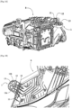
- a device comprises, in a traditional manner, at least one tab 1 projecting from the upper part of the housing B and intended for attachment to the structure of the vehicle, as illustrated by the Figure 1A ,
- the invention however consists of providing only a single tab 1 to ensure the fixing of the housing B while jointly having specific functions which are able to be provided by this single tab. These functions are essentially, the evacuation of water likely to stagnate on the wall of the housing B, the creation of a breakable zone selectively located on the tab so as to allow easy separation thereof in the event of heavy stress. mechanical and the presence of means of anchoring a replacement leg in the event of breakage of the original leg.
- the fixing bracket 1 comprises, as illustrated in detail on the figures 1B And 1 C , a first part 11 for connection to housing B in which orifices 10 are provided for water drainage.
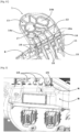
- the water evacuation orifices 10 are provided between longitudinal reinforcing ribs 16 and, in the embodiment shown, in particular, on the Figure 1C , the first part 11 here comprises five adjacent orifices 10.
- the first part 11 of the tab 1 further comprises studs 15 intended to ensure the assembly of the housing B with a replacement tab (not shown), in the event of breakage of the original tab.
- These studs 15 are carried by the longitudinal ribs 16 and possibly have a tapped bore for installing screws.
- This first part 11 extends outwards by a second part 12 comprising a breakable zone.
- the longitudinal ribs 16 present on the second part 12 weakening lines 12a intended to selectively locate the break while facilitating it.
- These weakening lines 12a are, for example, obtained by a restriction of material.
- the longitudinal ribs 16 extend to a third part 13 located at the end of the tab 1 and connected to the second intermediate part 12.
- this third part is partially hollowed out and carries at least one socket and here two sockets 14a, 14b for receiving a fixing member on the vehicle (not shown).
- the tab 1 also carries a transverse stiffening rib 17 which extends perpendicular to the longitudinal ribs 16 and which delimits, at least partially, with these the so-called breakable zone, as is visible on the figure 2 which represents box B after separation from the original leg 1.
- the tab 1 can be made by injection molding a plastic material in a single piece with the wall of the housing B or by overmolding on the upper wall of the housing B.
- the studs 15 which are located near the interior ends of the longitudinal ribs 16, at the level of the connection zone to the upper wall of the housing B, are not affected by this break.
- the position of the studs 15 is such that the installation of a replacement tab is possible even if the original tab 1 which broke is not completely separated from the housing.
Landscapes
- Engineering & Computer Science (AREA)
- Mechanical Engineering (AREA)
- Non-Portable Lighting Devices Or Systems Thereof (AREA)
- Lighting Device Outwards From Vehicle And Optical Signal (AREA)
Description
- La présente invention revendique la priorité de la demande
française 1912200 déposée le 30 Octobre 2019 - L'invention s'applique au montage sur des véhicules automobiles de modules d'éclairage et de signalisation et, en particulier, des boîtiers de projecteurs.
- Plus particulièrement, l'invention concerne un dispositif de montage d'un boîtier de projecteur comprenant une patte multi-fonctions permettant d'assurer conjointement l'iso-statisme du projecteur sur la caisse du véhicule.
- Un module de projecteur comprend généralement une source d'éclairage (lampe Halogène, Xénon, LED) pilotée par une carte électronique (PCB) et associée à divers composants optiques (lentille, réflecteur ...), l'ensemble étant destiné à être encapsulé dans un boîtier. Ce boîtier est soit fermé sur l'avant en étant obturé par une glace, soit ouvert sur l'avant et ce sont alors les lentilles qui assurent l'étanchéité vis-à-vis de l'environnement extérieur.
- Pour des raisons de style, un projecteur présente une structure et un profil qui sont spécifiques à chaque véhicule. En particulier, la géométrie de ses éléments constitutifs (le boîtier, la glace ou les lentilles) est conçue en fonction de l'environnement du projecteur sur le véhicule et de la conception de ses composants internes.
- En outre, les contraintes normatives ou réglementaires et de qualité imposent au projecteur d'assurer certaines propriétés ou fonctions, telles que l'évacuation de l'eau, la présence de zones de rupture pré-localisées des pattes et d'organes de réception d'un kit de remplacement de la patte en service après-vente.
- Dans ce contexte, le dispositif de montage du projecteur comprend des pattes faisant saillie sur la paroi du boîtier qui sont fixées, généralement par vissage, sur les armatures du véhicule. Ces pattes doivent être capables de maintenir le projecteur dans une position et une orientation qui correspondent à un bon iso-statisme, l'objectif étant de gérer les jeux et l'affleurement en respectant le référentiel technique.
- Le brevet
FR2986774B1 - Cependant, ce support ne décrit pas, ni ne suggère un quelconque moyen de fixation d'un projecteur permettant de remplir le cahier des charges imposé en assurant conjointement les multiples fonctions définies ci-dessus.
- On connaît par le document
CN102381240 un assemblage de phares automobiles combinés. On connaît par le documentJP2018069952 WO2010/001037 un agencement pour une partie avant de véhicule automobile. D'autres projecteurs sont connus par les documentsCN 109 466 421 A ouEP 3 412 506 A1 . - Dans ce contexte, l'invention propose un dispositif de montage comprenant une patte multifonctions assurant à elle-seule la fixation du boîtier de projecteur sur la caisse du véhicule.
- Ce but est atteint au moyen d'un projecteur selon la revendication 1.
- Selon l'invention, la première partie de la patte comporte, en outre, des plots destinés à assurer l'assemblage du boîtier avec une patte de remplacement en cas de rupture de la patte d'origine.
- Selon l'invention, les orifices d'évacuation d'eau sont ménagés entre des nervures longitudinales de renfort.
- Selon l'invention, les plots pour l'assemblage avec une patte de remplacement sont portés par les nervures longitudinales.
- Selon encore une autre caractéristique, les nervures longitudinales se prolongent jusque sur la troisième partie en présentant sur la seconde partie des lignes d'affaiblissement formant la zone sécable.
- Selon une variante spécifique, la patte de fixation porte une nervure transversale de rigidification s'étendant perpendiculairement aux nervures longitudinales et délimitant avec ces dernières la zone dite sécable.
- Selon une autre variante de réalisation, la troisième partie de la patte est partiellement évidée.
- Selon encore une autre variante, il est prévu que la première partie comporte cinq orifices d'évacuation d'eau et la troisième partie porte deux douilles de réception des organes de fixation sur le véhicule.
- Dans ce cas, l'une des douilles de réception des organes de fixation a une section circulaire tandis que l'autre douille a une section oblongue.
- Un autre objet de l'invention est un projecteur muni d'un dispositif de montage présentant les caractéristiques mentionnées ci-dessus pour la fixation sur la structure d'un véhicule automobile.
- La patte de fixation intégrée au dispositif de l'invention assure, à elle-seule et de manière fiable et efficace, le montage du boîtier de projecteur sur la structure d'un véhicule ainsi que plusieurs fonctions complémentaires.
- Le dispositif de l'invention présente un intérêt technico-économique significatif, d'une part, en s'affranchissant de l'utilisation de pièces supplémentaires et, d'autre part, en permettant à la fois une standardisation de l'interface du boîtier et du véhicule et en garantissant des opérations de maintenance aisées et rapides avec un référencement de très peu de pièces.
- D'autres caractéristiques et avantages de l'invention ressortiront à la lecture de la description qui va suivre, en référence aux figures annexées et détaillées ci-après.
- [
Fig. 1A ] est une vue d'ensemble en perspective d'un boîtier de projecteur pourvu d'un mode de réalisation du dispositif de montage selon l'invention. - [
Fig. 1B ] est une vue de détail en perspective boîtier de lafigure 1A avec le dispositif de l'invention. - [
Fig. 1C ] est une vue en perspective de la patte de fixation du dispositif de montage selon l'invention. - [
Fig. 2 ] est une vue de détail de face du boîtier de lafigure 1A après rupture de la patte de fixation de lafigure 2 . - Pour plus de clarté, les éléments identiques ou similaires sont repérés par des signes de référence identiques sur l'ensemble des figures.
- Naturellement, les modes de mise en oeuvre du procédé de l'invention illustrés par les figures présentées ci-dessus et décrites ci-après, ne sont donnés qu'à titre d'exemples non limitatifs. Il est explicitement prévu que l'on puisse proposer et combiner entre eux différents modes pour en proposer d'autres.
- Le dispositif de l'invention est destiné au montage d'un boîtier B de projecteur sur la structure d'un véhicule automobile. Un tel dispositif comprend, de manière traditionnelle, au moins une patte 1 faisant saillie à la partie supérieure du boîtier B et destinée à la fixation sur la structure du véhicule, comme illustré par la
figure 1A , - Dans ce cadre, l'invention consiste toutefois à ne prévoir qu'une seule patte 1 pour assurer la fixation du boîtier B tout en disposant conjointement de fonctions spécifiques qui sont à même d'être apportées par cette unique patte. Ces fonctions sont essentiellement, l'évacuation de l'eau susceptible de stagner sur la paroi du boîtier B, la réalisation d'une zone sécable localisée sélectivement sur la patte de façon à permettre une séparation aisée de celle-ci en cas de fortes sollicitations mécaniques et la présence de moyens d'ancrage d'une patte de remplacement en cas de rupture de la patte d'origine.
- A cet effet, la patte de fixation 1 comprend, comme illustré en détail sur les
figures 1B et1C , une première partie 11 pour le raccordement au boîtier B dans laquelle sont ménagés des orifices 10 pour l'évacuation d'eau. - Les orifices 10 d'évacuation d'eau sont ménagés entre des nervures longitudinales 16 de renfort et, dans le mode de réalisation représenté, notamment, sur la
figure 1C , la première partie 11 comporte ici cinq orifices 10 adjacents. - La première partie 11 de la patte 1 comporte, en outre, des plots 15 destinés à assurer l'assemblage du boîtier B avec une patte de remplacement (non représentée), en cas de rupture de la patte d'origine. Ces plots 15 sont portés par les nervures longitudinales 16 et présentent, éventuellement, un alésage taraudé pour la pose de vis.
- Cette première partie 11 se prolonge vers l'extérieur par une seconde partie 12 comportant une zone sécable. A cet effet, les nervures longitudinales 16 présentent sur la seconde partie 12 des lignes d'affaiblissement 12a destinées à localiser sélectivement la rupture tout en la facilitant. Ces lignes d'affaiblissement 12a sont, par exemple, obtenues par une restriction de matière.
- Les nervures longitudinales 16 se prolongent jusque sur une troisième partie 13 située à l'extrémité de la patte 1 et reliée à la seconde partie intermédiaire 12. Dans un but d'allègement, cette troisième partie est partiellement évidée et porte au moins une douille et ici deux douilles 14a, 14b de réception d'un organe de fixation sur le véhicule (non représenté).
- La patte 1 porte, en outre, une nervure transversale 17 de rigidification qui s'étend perpendiculairement aux nervures longitudinales 16 et qui délimite, au moins partiellement, avec celles-ci la zone dite sécable, comme cela est visible sur la
figure 2 qui représente le boîtier B après séparation de la patte 1 d'origine. - La patte 1 peut être réalisée par moulage à injection d'une matière plastique de façon monobloc avec la paroi du boîtier B ou par surmoulage sur la paroi supérieure du boîtier B.
- Comme illustré par la
figure 2 , la rupture de la patte 1 qui se produit, par exemple, sous l'effet d'un choc, s'est faite le long d'une ligne transversale R située au-dessus des orifices 10 de telle sorte que la fonction d'évacuation de l'eau est conservée, y compris après la pose d'une patte de remplacement. - De même les plots 15 qui sont situés à proximité des extrémités intérieures des nervures longitudinales 16, au niveau de la zone de raccordement à la paroi supérieure du boîtier B, ne sont pas affectés par cette rupture. La position des plots 15 est telle que la pose d'une patte de remplacement est possible même si la patte d'origine 1 qui s'est rompue n'est pas totalement séparée du boîtier.
Claims (6)
- Projecteur muni d'un dispositif de montage d'un boîtier (B) de projecteur sur un véhicule automobile, comprenant au moins une patte (1) faisant saillie à la partie supérieure du boîtier et destinée à la fixation sur la structure du véhicule, caractérisé en ce que ladite patte (1) comprend une première partie (11) de raccordement au boîtier (B) dans laquelle sont ménagés des orifices (10) pour l'évacuation d'eau, susceptible de stagner sur une paroi du boîtier (B), qui se prolonge vers l'extérieur par une seconde partie (12) comportant une zone sécable elle-même reliée à une troisième partie (13) d'extrémité portant au moins une douille (14a, 14b) de réception d'un organe de fixation sur le véhicule ; lesdits orifices (10) d'évacuation d'eau sont ménagés entre des nervures longitudinales (16) de renfort, caractérisé en ce que la première partie (11) de la patte (1) comporte, en outre, des plots (15) destinés à assurer l'assemblage du boîtier (B) avec une patte de remplacement en cas de rupture de la patte (1) d'origine ;
les plots (15) sont portés par lesdites nervures (16). - Projecteur selon la revendication 1, caractérisé en ce que lesdites nervures (16) se prolongent jusque sur la troisième partie (13) en présentant sur la seconde partie (12) des lignes d'affaiblissement (12a) formant la zone sécable.
- Projecteur selon l'une des revendications précédentes, caractérisé en ce que ladite patte (1) porte une nervure transversale (17) de rigidification s'étendant perpendiculairement aux nervures longitudinales (16) et délimitant, avec ces dernières, ladite zone sécable.
- Projecteur selon l'une des revendications précédentes, caractérisé en ce que la troisième partie (13) de ladite patte (1) est partiellement évidée.
- Projecteur selon l'une des revendications précédentes, caractérisé en ce que la première partie (11) comporte cinq orifices (10) d'évacuation d'eau et la troisième partie (13) porte deux douilles (14a, 14b) de réception des organes de fixation sur le véhicule.
- Projecteur selon la revendication précédente, caractérisé en ce que l'une (14a) desdites douilles de réception des organes de fixation a une section circulaire tandis que l'autre douille (14b) a une section oblongue.
Applications Claiming Priority (2)
| Application Number | Priority Date | Filing Date | Title |
|---|---|---|---|
| FR1912200A FR3102830A1 (fr) | 2019-10-30 | 2019-10-30 | Dispositif de montage d’un boîtier de projecteur sur un véhicule automobile |
| PCT/FR2020/051844 WO2021084182A1 (fr) | 2019-10-30 | 2020-10-15 | Dispositif de montage d'un boîtier de projecteur sur un véhicule automobile |
Publications (3)
| Publication Number | Publication Date |
|---|---|
| EP4051536A1 EP4051536A1 (fr) | 2022-09-07 |
| EP4051536B1 true EP4051536B1 (fr) | 2023-11-29 |
| EP4051536B8 EP4051536B8 (fr) | 2024-01-03 |
Family
ID=69700012
Family Applications (1)
| Application Number | Title | Priority Date | Filing Date |
|---|---|---|---|
| EP20799781.8A Active EP4051536B8 (fr) | 2019-10-30 | 2020-10-15 | Projecteur de véhicule automobile |
Country Status (4)
| Country | Link |
|---|---|
| EP (1) | EP4051536B8 (fr) |
| CN (1) | CN114616133B (fr) |
| FR (1) | FR3102830A1 (fr) |
| WO (1) | WO2021084182A1 (fr) |
Family Cites Families (13)
| Publication number | Priority date | Publication date | Assignee | Title |
|---|---|---|---|---|
| JP3937577B2 (ja) * | 1998-05-08 | 2007-06-27 | 市光工業株式会社 | 車両用装置 |
| JP5015734B2 (ja) * | 2007-11-19 | 2012-08-29 | 株式会社小糸製作所 | 車輌用ヘッドランプ |
| FR2933371B1 (fr) * | 2008-07-01 | 2010-08-13 | Renault Sas | Agencement pour une partie avant de vehicule automobile |
| CN102381240A (zh) * | 2011-09-01 | 2012-03-21 | 安徽江淮汽车股份有限公司 | 一种汽车前组合灯总成 |
| JP5737717B2 (ja) * | 2011-09-29 | 2015-06-17 | ダイハツ工業株式会社 | 車両衝突時の緩衝構造 |
| FR2986774A1 (fr) | 2012-02-13 | 2013-08-16 | Renault Sa | Support multifonctions pour le montage d'elements fonctionnels d'un vehicule automobile |
| JP6194511B2 (ja) * | 2013-11-19 | 2017-09-13 | トヨタ車体株式会社 | ランプの取付構造 |
| JP6729990B2 (ja) * | 2016-10-31 | 2020-07-29 | ダイハツ工業株式会社 | 車両構造 |
| FR3067306B1 (fr) * | 2017-06-08 | 2020-08-28 | Peugeot Citroen Automobiles Sa | Bloc optique pour vehicule automobile |
| FR3068313B1 (fr) * | 2017-06-29 | 2020-10-02 | Valeo Vision Belgique | Dispositif d'eclairage pour vehicule automobile muni d'un faisceau electrique guide |
| FR3076504A1 (fr) * | 2018-01-05 | 2019-07-12 | Psa Automobiles Sa | Boitier de bloc optique et patte de fixation de substitution pour la reparation d’un tel bloc optique de vehicule |
| US11148578B2 (en) * | 2018-03-25 | 2021-10-19 | Maurice Paperi | Universal mounting tabs and kits for automotive components |
| CN109466421B (zh) * | 2018-11-19 | 2020-07-07 | 神龙汽车有限公司 | 一种车灯与车灯框架连接结构 |
-
2019
- 2019-10-30 FR FR1912200A patent/FR3102830A1/fr not_active Ceased
-
2020
- 2020-10-15 EP EP20799781.8A patent/EP4051536B8/fr active Active
- 2020-10-15 WO PCT/FR2020/051844 patent/WO2021084182A1/fr not_active Ceased
- 2020-10-15 CN CN202080076706.XA patent/CN114616133B/zh active Active
Also Published As
| Publication number | Publication date |
|---|---|
| FR3102830A1 (fr) | 2021-05-07 |
| CN114616133B (zh) | 2025-09-26 |
| CN114616133A (zh) | 2022-06-10 |
| EP4051536A1 (fr) | 2022-09-07 |
| EP4051536B8 (fr) | 2024-01-03 |
| WO2021084182A1 (fr) | 2021-05-06 |
Similar Documents
| Publication | Publication Date | Title |
|---|---|---|
| FR3083514A1 (fr) | Systeme de retenue des bords d’un element de carrosserie au niveau de l’ouverture d’implantation d’un systeme d’eclairage et/ou de signalisation | |
| EP4051536B1 (fr) | Projecteur de véhicule automobile | |
| EP0586279A1 (fr) | Plaque frontale monobloc pour véhicule automobile | |
| EP3815972B1 (fr) | Dispositif de support et de connexion d'une carte électronique pour le pilotage d'un module d éclairage ou de signalisation de véhicule automobile | |
| FR2698334A1 (fr) | Agencement de véhicule automobile comportant un élément unique antérieur de carrosserie en forme de coquille. | |
| EP1736358A1 (fr) | Projecteur de véhicule automobile | |
| EP2479062B1 (fr) | Equipement électrique pour véhicule automobile, en particulier dispositif d'eclairage ou de signalisation | |
| FR2975953A1 (fr) | Systeme d'eclairage pour vehicule | |
| FR3110519A1 (fr) | Support de fixation de parechoc pour véhicule automobile | |
| EP1004820A1 (fr) | Luminaire, en particulier de type hublot ou applique, à joint d'étanchéité entre le couvercle et le socle | |
| FR3058502B1 (fr) | Dispositif de montage sans vis d'un boitier de commande de projecteur sur ledit projecteur | |
| FR2835595A1 (fr) | Douille de lampe pour projecteur de vehicule automobile, et reflecteur de projecteur destine a recevoir une telle douille de lampe. | |
| EP2299553B1 (fr) | Coffret électrique à fixer à une paroi | |
| EP0995947B1 (fr) | Feu de signalisation à porte-lampe integré au socle | |
| WO2020225492A1 (fr) | Boîtier de module de signalisation pour véhicules automobiles et véhicule équipé dudit module | |
| EP3881003B1 (fr) | Bloc optique pour véhicule automobile pourvu d'un masque fixé sur une armature | |
| FR3100868A1 (fr) | Elément d’obturation pour projecteur d’un véhicule automobile | |
| FR2984461A1 (fr) | Ensemble d'un projecteur pour vehicule automobile et d'au moins un module de remplacement, et procede de remise en etat du projecteur | |
| FR2972401A1 (fr) | Equipement electrique, tel qu'un dispositif d'eclairage ou de signalisation, pour vehicule automobile | |
| EP3867103B1 (fr) | Véhicule automobile comportant au moins un projecteur avec ou sans glace de protection | |
| FR3085066A1 (fr) | Module d’eclairage pour un projecteur de vehicule automobile sans glace et son procede d’assemblage | |
| FR2918956A1 (fr) | Systeme d'assemblage d'un masque sur un boitier de projecteur pour vehicule automobile. | |
| FR2835594A1 (fr) | Douille de lampe pour projecteur de vehicule automobile, et reflecteur de projecteur destine a recevoir une telle douille de lampe | |
| FR2972165A1 (fr) | Dispositif d'aide aux interventions a l'interieur d'une partie arriere d'un bloc optique de vehicule | |
| FR3065703A1 (fr) | Agencement pour vehicule automobile comprenant un element de carrosserie et un dispositif d’eclairage et/ou de signalisation implante dans ledit element de carrosserie. |
Legal Events
| Date | Code | Title | Description |
|---|---|---|---|
| STAA | Information on the status of an ep patent application or granted ep patent |
Free format text: STATUS: UNKNOWN |
|
| STAA | Information on the status of an ep patent application or granted ep patent |
Free format text: STATUS: THE INTERNATIONAL PUBLICATION HAS BEEN MADE |
|
| PUAI | Public reference made under article 153(3) epc to a published international application that has entered the european phase |
Free format text: ORIGINAL CODE: 0009012 |
|
| STAA | Information on the status of an ep patent application or granted ep patent |
Free format text: STATUS: REQUEST FOR EXAMINATION WAS MADE |
|
| 17P | Request for examination filed |
Effective date: 20220329 |
|
| AK | Designated contracting states |
Kind code of ref document: A1 Designated state(s): AL AT BE BG CH CY CZ DE DK EE ES FI FR GB GR HR HU IE IS IT LI LT LU LV MC MK MT NL NO PL PT RO RS SE SI SK SM TR |
|
| DAV | Request for validation of the european patent (deleted) | ||
| DAX | Request for extension of the european patent (deleted) | ||
| GRAP | Despatch of communication of intention to grant a patent |
Free format text: ORIGINAL CODE: EPIDOSNIGR1 |
|
| STAA | Information on the status of an ep patent application or granted ep patent |
Free format text: STATUS: GRANT OF PATENT IS INTENDED |
|
| INTG | Intention to grant announced |
Effective date: 20230628 |
|
| GRAS | Grant fee paid |
Free format text: ORIGINAL CODE: EPIDOSNIGR3 |
|
| GRAA | (expected) grant |
Free format text: ORIGINAL CODE: 0009210 |
|
| STAA | Information on the status of an ep patent application or granted ep patent |
Free format text: STATUS: THE PATENT HAS BEEN GRANTED |
|
| REG | Reference to a national code |
Ref country code: DE Ref legal event code: R081 Ref document number: 602020022030 Country of ref document: DE Owner name: STELLANTIS AUTO SAS, FR Free format text: FORMER OWNER: PSA AUTOMOBILES SA, POISSY, FR |
|
| AK | Designated contracting states |
Kind code of ref document: B1 Designated state(s): AL AT BE BG CH CY CZ DE DK EE ES FI FR GB GR HR HU IE IS IT LI LT LU LV MC MK MT NL NO PL PT RO RS SE SI SK SM TR |
|
| REG | Reference to a national code |
Ref country code: GB Ref legal event code: FG4D Free format text: NOT ENGLISH |
|
| REG | Reference to a national code |
Ref country code: CH Ref legal event code: EP |
|
| REG | Reference to a national code |
Ref country code: DE Ref legal event code: R084 Ref document number: 602020022030 Country of ref document: DE |
|
| RAP4 | Party data changed (patent owner data changed or rights of a patent transferred) |
Owner name: STELLANTIS AUTO SAS |
|
| REG | Reference to a national code |
Ref country code: DE Ref legal event code: R096 Ref document number: 602020022030 Country of ref document: DE |
|
| REG | Reference to a national code |
Ref country code: CH Ref legal event code: PK Free format text: RECTIFICATION B8 |
|
| REG | Reference to a national code |
Ref country code: IE Ref legal event code: FG4D Free format text: LANGUAGE OF EP DOCUMENT: FRENCH |
|
| REG | Reference to a national code |
Ref country code: GB Ref legal event code: 746 Effective date: 20231227 |
|
| REG | Reference to a national code |
Ref country code: LT Ref legal event code: MG9D |
|
| REG | Reference to a national code |
Ref country code: NL Ref legal event code: MP Effective date: 20231129 |
|
| PG25 | Lapsed in a contracting state [announced via postgrant information from national office to epo] |
Ref country code: GR Free format text: LAPSE BECAUSE OF FAILURE TO SUBMIT A TRANSLATION OF THE DESCRIPTION OR TO PAY THE FEE WITHIN THE PRESCRIBED TIME-LIMIT Effective date: 20240301 |
|
| PG25 | Lapsed in a contracting state [announced via postgrant information from national office to epo] |
Ref country code: IS Free format text: LAPSE BECAUSE OF FAILURE TO SUBMIT A TRANSLATION OF THE DESCRIPTION OR TO PAY THE FEE WITHIN THE PRESCRIBED TIME-LIMIT Effective date: 20240329 |
|
| PG25 | Lapsed in a contracting state [announced via postgrant information from national office to epo] |
Ref country code: LT Free format text: LAPSE BECAUSE OF FAILURE TO SUBMIT A TRANSLATION OF THE DESCRIPTION OR TO PAY THE FEE WITHIN THE PRESCRIBED TIME-LIMIT Effective date: 20231129 |
|
| PG25 | Lapsed in a contracting state [announced via postgrant information from national office to epo] |
Ref country code: ES Free format text: LAPSE BECAUSE OF FAILURE TO SUBMIT A TRANSLATION OF THE DESCRIPTION OR TO PAY THE FEE WITHIN THE PRESCRIBED TIME-LIMIT Effective date: 20231129 |
|
| PG25 | Lapsed in a contracting state [announced via postgrant information from national office to epo] |
Ref country code: LT Free format text: LAPSE BECAUSE OF FAILURE TO SUBMIT A TRANSLATION OF THE DESCRIPTION OR TO PAY THE FEE WITHIN THE PRESCRIBED TIME-LIMIT Effective date: 20231129 Ref country code: IS Free format text: LAPSE BECAUSE OF FAILURE TO SUBMIT A TRANSLATION OF THE DESCRIPTION OR TO PAY THE FEE WITHIN THE PRESCRIBED TIME-LIMIT Effective date: 20240329 Ref country code: GR Free format text: LAPSE BECAUSE OF FAILURE TO SUBMIT A TRANSLATION OF THE DESCRIPTION OR TO PAY THE FEE WITHIN THE PRESCRIBED TIME-LIMIT Effective date: 20240301 Ref country code: ES Free format text: LAPSE BECAUSE OF FAILURE TO SUBMIT A TRANSLATION OF THE DESCRIPTION OR TO PAY THE FEE WITHIN THE PRESCRIBED TIME-LIMIT Effective date: 20231129 Ref country code: BG Free format text: LAPSE BECAUSE OF FAILURE TO SUBMIT A TRANSLATION OF THE DESCRIPTION OR TO PAY THE FEE WITHIN THE PRESCRIBED TIME-LIMIT Effective date: 20240229 |
|
| REG | Reference to a national code |
Ref country code: AT Ref legal event code: MK05 Ref document number: 1635804 Country of ref document: AT Kind code of ref document: T Effective date: 20231129 |
|
| PG25 | Lapsed in a contracting state [announced via postgrant information from national office to epo] |
Ref country code: NL Free format text: LAPSE BECAUSE OF FAILURE TO SUBMIT A TRANSLATION OF THE DESCRIPTION OR TO PAY THE FEE WITHIN THE PRESCRIBED TIME-LIMIT Effective date: 20231129 |
|
| PG25 | Lapsed in a contracting state [announced via postgrant information from national office to epo] |
Ref country code: SE Free format text: LAPSE BECAUSE OF FAILURE TO SUBMIT A TRANSLATION OF THE DESCRIPTION OR TO PAY THE FEE WITHIN THE PRESCRIBED TIME-LIMIT Effective date: 20231129 Ref country code: RS Free format text: LAPSE BECAUSE OF FAILURE TO SUBMIT A TRANSLATION OF THE DESCRIPTION OR TO PAY THE FEE WITHIN THE PRESCRIBED TIME-LIMIT Effective date: 20231129 Ref country code: PL Free format text: LAPSE BECAUSE OF FAILURE TO SUBMIT A TRANSLATION OF THE DESCRIPTION OR TO PAY THE FEE WITHIN THE PRESCRIBED TIME-LIMIT Effective date: 20231129 Ref country code: NO Free format text: LAPSE BECAUSE OF FAILURE TO SUBMIT A TRANSLATION OF THE DESCRIPTION OR TO PAY THE FEE WITHIN THE PRESCRIBED TIME-LIMIT Effective date: 20240229 Ref country code: NL Free format text: LAPSE BECAUSE OF FAILURE TO SUBMIT A TRANSLATION OF THE DESCRIPTION OR TO PAY THE FEE WITHIN THE PRESCRIBED TIME-LIMIT Effective date: 20231129 Ref country code: LV Free format text: LAPSE BECAUSE OF FAILURE TO SUBMIT A TRANSLATION OF THE DESCRIPTION OR TO PAY THE FEE WITHIN THE PRESCRIBED TIME-LIMIT Effective date: 20231129 Ref country code: HR Free format text: LAPSE BECAUSE OF FAILURE TO SUBMIT A TRANSLATION OF THE DESCRIPTION OR TO PAY THE FEE WITHIN THE PRESCRIBED TIME-LIMIT Effective date: 20231129 |
|
| PG25 | Lapsed in a contracting state [announced via postgrant information from national office to epo] |
Ref country code: DK Free format text: LAPSE BECAUSE OF FAILURE TO SUBMIT A TRANSLATION OF THE DESCRIPTION OR TO PAY THE FEE WITHIN THE PRESCRIBED TIME-LIMIT Effective date: 20231129 |
|
| PG25 | Lapsed in a contracting state [announced via postgrant information from national office to epo] |
Ref country code: AT Free format text: LAPSE BECAUSE OF FAILURE TO SUBMIT A TRANSLATION OF THE DESCRIPTION OR TO PAY THE FEE WITHIN THE PRESCRIBED TIME-LIMIT Effective date: 20231129 |
|
| PG25 | Lapsed in a contracting state [announced via postgrant information from national office to epo] |
Ref country code: SK Free format text: LAPSE BECAUSE OF FAILURE TO SUBMIT A TRANSLATION OF THE DESCRIPTION OR TO PAY THE FEE WITHIN THE PRESCRIBED TIME-LIMIT Effective date: 20231129 |
|
| PG25 | Lapsed in a contracting state [announced via postgrant information from national office to epo] |
Ref country code: SM Free format text: LAPSE BECAUSE OF FAILURE TO SUBMIT A TRANSLATION OF THE DESCRIPTION OR TO PAY THE FEE WITHIN THE PRESCRIBED TIME-LIMIT Effective date: 20231129 Ref country code: SK Free format text: LAPSE BECAUSE OF FAILURE TO SUBMIT A TRANSLATION OF THE DESCRIPTION OR TO PAY THE FEE WITHIN THE PRESCRIBED TIME-LIMIT Effective date: 20231129 Ref country code: RO Free format text: LAPSE BECAUSE OF FAILURE TO SUBMIT A TRANSLATION OF THE DESCRIPTION OR TO PAY THE FEE WITHIN THE PRESCRIBED TIME-LIMIT Effective date: 20231129 Ref country code: IT Free format text: LAPSE BECAUSE OF FAILURE TO SUBMIT A TRANSLATION OF THE DESCRIPTION OR TO PAY THE FEE WITHIN THE PRESCRIBED TIME-LIMIT Effective date: 20231129 Ref country code: EE Free format text: LAPSE BECAUSE OF FAILURE TO SUBMIT A TRANSLATION OF THE DESCRIPTION OR TO PAY THE FEE WITHIN THE PRESCRIBED TIME-LIMIT Effective date: 20231129 Ref country code: DK Free format text: LAPSE BECAUSE OF FAILURE TO SUBMIT A TRANSLATION OF THE DESCRIPTION OR TO PAY THE FEE WITHIN THE PRESCRIBED TIME-LIMIT Effective date: 20231129 Ref country code: AT Free format text: LAPSE BECAUSE OF FAILURE TO SUBMIT A TRANSLATION OF THE DESCRIPTION OR TO PAY THE FEE WITHIN THE PRESCRIBED TIME-LIMIT Effective date: 20231129 |
|
| PG25 | Lapsed in a contracting state [announced via postgrant information from national office to epo] |
Ref country code: PT Free format text: LAPSE BECAUSE OF FAILURE TO SUBMIT A TRANSLATION OF THE DESCRIPTION OR TO PAY THE FEE WITHIN THE PRESCRIBED TIME-LIMIT Effective date: 20240401 |
|
| PG25 | Lapsed in a contracting state [announced via postgrant information from national office to epo] |
Ref country code: PT Free format text: LAPSE BECAUSE OF FAILURE TO SUBMIT A TRANSLATION OF THE DESCRIPTION OR TO PAY THE FEE WITHIN THE PRESCRIBED TIME-LIMIT Effective date: 20240401 |
|
| REG | Reference to a national code |
Ref country code: DE Ref legal event code: R097 Ref document number: 602020022030 Country of ref document: DE |
|
| PLBE | No opposition filed within time limit |
Free format text: ORIGINAL CODE: 0009261 |
|
| STAA | Information on the status of an ep patent application or granted ep patent |
Free format text: STATUS: NO OPPOSITION FILED WITHIN TIME LIMIT |
|
| PGFP | Annual fee paid to national office [announced via postgrant information from national office to epo] |
Ref country code: CZ Payment date: 20240924 Year of fee payment: 5 |
|
| PG25 | Lapsed in a contracting state [announced via postgrant information from national office to epo] |
Ref country code: SI Free format text: LAPSE BECAUSE OF FAILURE TO SUBMIT A TRANSLATION OF THE DESCRIPTION OR TO PAY THE FEE WITHIN THE PRESCRIBED TIME-LIMIT Effective date: 20231129 |
|
| PG25 | Lapsed in a contracting state [announced via postgrant information from national office to epo] |
Ref country code: SI Free format text: LAPSE BECAUSE OF FAILURE TO SUBMIT A TRANSLATION OF THE DESCRIPTION OR TO PAY THE FEE WITHIN THE PRESCRIBED TIME-LIMIT Effective date: 20231129 |
|
| 26N | No opposition filed |
Effective date: 20240830 |
|
| REG | Reference to a national code |
Ref country code: CH Ref legal event code: PL |
|
| PG25 | Lapsed in a contracting state [announced via postgrant information from national office to epo] |
Ref country code: MC Free format text: LAPSE BECAUSE OF FAILURE TO SUBMIT A TRANSLATION OF THE DESCRIPTION OR TO PAY THE FEE WITHIN THE PRESCRIBED TIME-LIMIT Effective date: 20231129 |
|
| PG25 | Lapsed in a contracting state [announced via postgrant information from national office to epo] |
Ref country code: LU Free format text: LAPSE BECAUSE OF NON-PAYMENT OF DUE FEES Effective date: 20241015 Ref country code: BE Free format text: LAPSE BECAUSE OF NON-PAYMENT OF DUE FEES Effective date: 20241031 |
|
| PG25 | Lapsed in a contracting state [announced via postgrant information from national office to epo] |
Ref country code: CH Free format text: LAPSE BECAUSE OF NON-PAYMENT OF DUE FEES Effective date: 20241031 |
|
| REG | Reference to a national code |
Ref country code: BE Ref legal event code: MM Effective date: 20241031 |
|
| PG25 | Lapsed in a contracting state [announced via postgrant information from national office to epo] |
Ref country code: FI Free format text: LAPSE BECAUSE OF FAILURE TO SUBMIT A TRANSLATION OF THE DESCRIPTION OR TO PAY THE FEE WITHIN THE PRESCRIBED TIME-LIMIT Effective date: 20231129 |
|
| PGFP | Annual fee paid to national office [announced via postgrant information from national office to epo] |
Ref country code: GB Payment date: 20250923 Year of fee payment: 6 |
|
| PGFP | Annual fee paid to national office [announced via postgrant information from national office to epo] |
Ref country code: FR Payment date: 20250924 Year of fee payment: 6 |
|
| PG25 | Lapsed in a contracting state [announced via postgrant information from national office to epo] |
Ref country code: IE Free format text: LAPSE BECAUSE OF NON-PAYMENT OF DUE FEES Effective date: 20241015 |
|
| PGFP | Annual fee paid to national office [announced via postgrant information from national office to epo] |
Ref country code: DE Payment date: 20250923 Year of fee payment: 6 |
|
| PG25 | Lapsed in a contracting state [announced via postgrant information from national office to epo] |
Ref country code: CY Free format text: LAPSE BECAUSE OF FAILURE TO SUBMIT A TRANSLATION OF THE DESCRIPTION OR TO PAY THE FEE WITHIN THE PRESCRIBED TIME-LIMIT; INVALID AB INITIO Effective date: 20201015 |
|
| PG25 | Lapsed in a contracting state [announced via postgrant information from national office to epo] |
Ref country code: HU Free format text: LAPSE BECAUSE OF FAILURE TO SUBMIT A TRANSLATION OF THE DESCRIPTION OR TO PAY THE FEE WITHIN THE PRESCRIBED TIME-LIMIT; INVALID AB INITIO Effective date: 20201015 |