EP4049765B1 - Mobile maschine zur schüttgutbehandlung mit beweglichem komponententräger über einer förderstrecke - Google Patents
Mobile maschine zur schüttgutbehandlung mit beweglichem komponententräger über einer förderstrecke Download PDFInfo
- Publication number
- EP4049765B1 EP4049765B1 EP22158097.0A EP22158097A EP4049765B1 EP 4049765 B1 EP4049765 B1 EP 4049765B1 EP 22158097 A EP22158097 A EP 22158097A EP 4049765 B1 EP4049765 B1 EP 4049765B1
- Authority
- EP
- European Patent Office
- Prior art keywords
- conveyor
- machine
- component carrier
- mobile machine
- relative
- Prior art date
- Legal status (The legal status is an assumption and is not a legal conclusion. Google has not performed a legal analysis and makes no representation as to the accuracy of the status listed.)
- Active
Links
Images



Classifications
-
- B—PERFORMING OPERATIONS; TRANSPORTING
- B65—CONVEYING; PACKING; STORING; HANDLING THIN OR FILAMENTARY MATERIAL
- B65G—TRANSPORT OR STORAGE DEVICES, e.g. CONVEYORS FOR LOADING OR TIPPING, SHOP CONVEYOR SYSTEMS OR PNEUMATIC TUBE CONVEYORS
- B65G41/00—Supporting frames or bases for conveyors as a whole, e.g. transportable conveyor frames
- B65G41/001—Supporting frames or bases for conveyors as a whole, e.g. transportable conveyor frames with the conveyor adjustably mounted on the supporting frame or base
- B65G41/002—Pivotably mounted
-
- B—PERFORMING OPERATIONS; TRANSPORTING
- B07—SEPARATING SOLIDS FROM SOLIDS; SORTING
- B07B—SEPARATING SOLIDS FROM SOLIDS BY SIEVING, SCREENING, SIFTING OR BY USING GAS CURRENTS; SEPARATING BY OTHER DRY METHODS APPLICABLE TO BULK MATERIAL, e.g. LOOSE ARTICLES FIT TO BE HANDLED LIKE BULK MATERIAL
- B07B1/00—Sieving, screening, sifting, or sorting solid materials using networks, gratings, grids, or the like
- B07B1/005—Transportable screening plants
-
- B—PERFORMING OPERATIONS; TRANSPORTING
- B65—CONVEYING; PACKING; STORING; HANDLING THIN OR FILAMENTARY MATERIAL
- B65G—TRANSPORT OR STORAGE DEVICES, e.g. CONVEYORS FOR LOADING OR TIPPING, SHOP CONVEYOR SYSTEMS OR PNEUMATIC TUBE CONVEYORS
- B65G15/00—Conveyors having endless load-conveying surfaces, i.e. belts and like continuous members, to which tractive effort is transmitted by means other than endless driving elements of similar configuration
- B65G15/30—Belts or like endless load-carriers
-
- B—PERFORMING OPERATIONS; TRANSPORTING
- B07—SEPARATING SOLIDS FROM SOLIDS; SORTING
- B07B—SEPARATING SOLIDS FROM SOLIDS BY SIEVING, SCREENING, SIFTING OR BY USING GAS CURRENTS; SEPARATING BY OTHER DRY METHODS APPLICABLE TO BULK MATERIAL, e.g. LOOSE ARTICLES FIT TO BE HANDLED LIKE BULK MATERIAL
- B07B13/00—Grading or sorting solid materials by dry methods, not otherwise provided for; Sorting articles otherwise than by indirectly controlled devices
- B07B13/14—Details or accessories
- B07B13/16—Feed or discharge arrangements
-
- B—PERFORMING OPERATIONS; TRANSPORTING
- B65—CONVEYING; PACKING; STORING; HANDLING THIN OR FILAMENTARY MATERIAL
- B65G—TRANSPORT OR STORAGE DEVICES, e.g. CONVEYORS FOR LOADING OR TIPPING, SHOP CONVEYOR SYSTEMS OR PNEUMATIC TUBE CONVEYORS
- B65G11/00—Chutes
- B65G11/02—Chutes of straight form
- B65G11/026—Chutes of straight form for bulk
-
- B—PERFORMING OPERATIONS; TRANSPORTING
- B65—CONVEYING; PACKING; STORING; HANDLING THIN OR FILAMENTARY MATERIAL
- B65G—TRANSPORT OR STORAGE DEVICES, e.g. CONVEYORS FOR LOADING OR TIPPING, SHOP CONVEYOR SYSTEMS OR PNEUMATIC TUBE CONVEYORS
- B65G21/00—Supporting or protective framework or housings for endless load-carriers or traction elements of belt or chain conveyors
- B65G21/10—Supporting or protective framework or housings for endless load-carriers or traction elements of belt or chain conveyors movable, or having interchangeable or relatively movable parts; Devices for moving framework or parts thereof
- B65G21/12—Supporting or protective framework or housings for endless load-carriers or traction elements of belt or chain conveyors movable, or having interchangeable or relatively movable parts; Devices for moving framework or parts thereof to allow adjustment of position of load-carrier or traction element as a whole
-
- B—PERFORMING OPERATIONS; TRANSPORTING
- B65—CONVEYING; PACKING; STORING; HANDLING THIN OR FILAMENTARY MATERIAL
- B65G—TRANSPORT OR STORAGE DEVICES, e.g. CONVEYORS FOR LOADING OR TIPPING, SHOP CONVEYOR SYSTEMS OR PNEUMATIC TUBE CONVEYORS
- B65G41/00—Supporting frames or bases for conveyors as a whole, e.g. transportable conveyor frames
- B65G41/007—Means for moving conveyor frames and control arrangements therefor
-
- B—PERFORMING OPERATIONS; TRANSPORTING
- B65—CONVEYING; PACKING; STORING; HANDLING THIN OR FILAMENTARY MATERIAL
- B65G—TRANSPORT OR STORAGE DEVICES, e.g. CONVEYORS FOR LOADING OR TIPPING, SHOP CONVEYOR SYSTEMS OR PNEUMATIC TUBE CONVEYORS
- B65G65/00—Loading or unloading
- B65G65/02—Loading or unloading machines comprising essentially a conveyor for moving the loads associated with a device for picking-up the loads
-
- B—PERFORMING OPERATIONS; TRANSPORTING
- B65—CONVEYING; PACKING; STORING; HANDLING THIN OR FILAMENTARY MATERIAL
- B65G—TRANSPORT OR STORAGE DEVICES, e.g. CONVEYORS FOR LOADING OR TIPPING, SHOP CONVEYOR SYSTEMS OR PNEUMATIC TUBE CONVEYORS
- B65G69/00—Auxiliary measures taken, or devices used, in connection with loading or unloading
- B65G69/12—Sieving bulk materials during loading or unloading
-
- B—PERFORMING OPERATIONS; TRANSPORTING
- B07—SEPARATING SOLIDS FROM SOLIDS; SORTING
- B07B—SEPARATING SOLIDS FROM SOLIDS BY SIEVING, SCREENING, SIFTING OR BY USING GAS CURRENTS; SEPARATING BY OTHER DRY METHODS APPLICABLE TO BULK MATERIAL, e.g. LOOSE ARTICLES FIT TO BE HANDLED LIKE BULK MATERIAL
- B07B2201/00—Details applicable to machines for screening using sieves or gratings
- B07B2201/04—Multiple deck screening devices comprising one or more superimposed screens
-
- B—PERFORMING OPERATIONS; TRANSPORTING
- B65—CONVEYING; PACKING; STORING; HANDLING THIN OR FILAMENTARY MATERIAL
- B65G—TRANSPORT OR STORAGE DEVICES, e.g. CONVEYORS FOR LOADING OR TIPPING, SHOP CONVEYOR SYSTEMS OR PNEUMATIC TUBE CONVEYORS
- B65G2201/00—Indexing codes relating to handling devices, e.g. conveyors, characterised by the type of product or load being conveyed or handled
- B65G2201/04—Bulk
-
- B—PERFORMING OPERATIONS; TRANSPORTING
- B65—CONVEYING; PACKING; STORING; HANDLING THIN OR FILAMENTARY MATERIAL
- B65G—TRANSPORT OR STORAGE DEVICES, e.g. CONVEYORS FOR LOADING OR TIPPING, SHOP CONVEYOR SYSTEMS OR PNEUMATIC TUBE CONVEYORS
- B65G2201/00—Indexing codes relating to handling devices, e.g. conveyors, characterised by the type of product or load being conveyed or handled
- B65G2201/04—Bulk
- B65G2201/042—Granular material
-
- B—PERFORMING OPERATIONS; TRANSPORTING
- B65—CONVEYING; PACKING; STORING; HANDLING THIN OR FILAMENTARY MATERIAL
- B65G—TRANSPORT OR STORAGE DEVICES, e.g. CONVEYORS FOR LOADING OR TIPPING, SHOP CONVEYOR SYSTEMS OR PNEUMATIC TUBE CONVEYORS
- B65G41/00—Supporting frames or bases for conveyors as a whole, e.g. transportable conveyor frames
- B65G41/007—Means for moving conveyor frames and control arrangements therefor
- B65G41/008—Means for moving conveyor frames and control arrangements therefor frames mounted on wheels or caterpillar
Definitions
- the present invention relates to a mobile, in particular self-propelled, machine according to the preamble of claim 1.
- Such a mobile machine in the form of a mobile screening system is from the US 2020/0384504 A1 known.
- the known machine has a feeding unit which is fed with bulk material by a conveyor device or by a conveyor vehicle.
- the feeding unit transfers bulk material to the conveyor assembly at a longitudinal end of the same, from where the conveyor assembly conveys the bulk material to a transfer longitudinal end, at which the conveyor assembly transfers the bulk material remaining on the conveyor path to at least one take-off belt.
- the bulk material is separated depending on the grain size by a sieve formed on the bottom of the conveyor assembly. The fractions obtained in this way are fed to different extraction belts and transported away from the screening plant for further processing.
- the conveyor section is designed like a trough and includes a bottom designed as a sieve, which is delimited on both sides by side walls which form a physical barrier for the bulk material located on the conveyor section, so that it cannot fall down to the side but, apart from a sorting movement during sieving, only moved along the conveyor track.
- the conveyor assembly with the trough-like conveyor section described can be raised relative to the machine frame for maintenance purposes by pivoting about a maintenance pivot axis located closer to the longitudinal end of the feed.
- Carrier holders are rigidly connected to the side walls of the conveyor section and protrude upwards over the edge of the side walls. At their longitudinal ends remote from the side cheeks, the carrier holders are connected by a component carrier, which spans the conveyor path essentially parallel to the maintenance pivot axis.
- the component carrier carries a material brake in the form of a curtain, which, as a mechanical resistance to movement, is intended to prevent excessive conveying speeds of the bulk material on the conveying route.
- this component carrier which spans the conveyor section in a bridge-like manner, can lead to the following problems: the conveyor assembly often forms a sieve conveyor assembly, which is arranged as high as possible on the machine frame, i.e. away from the base of the machine, so that the sieve of the conveyor assembly can pass through Grain size fractions can fall through the sieve under gravity, if necessary into further sieving devices for further sorting.
- the component carrier can then project beyond the conveyor assembly in the height direction to such an extent that the component carrier exceeds a permissible transport silhouette of the machine. The component carrier must then be removed to transport the machine.
- the component carrier fixed to the side walls of the vibration conveyor assembly is loaded by the vibrations of the conveyor assembly, so that it can either only carry very robust functional assemblies or with an intermediate arrangement must be connected to the side panels using complex vibration decoupling.
- the component carrier would not move with the conveyor assembly and could hinder its movement into a maintenance position that is raised relative to the machine frame. If the component carrier were attached to the machine frame in the height direction at such a large distance from the conveyor path that it would no longer hinder the lifting of the conveyor assembly, the previously described problem of exceeding the transport silhouette would arise again. In addition, the component carrier cannot be arranged arbitrarily far above the conveyor path without this affecting the functionality of the functional modules arranged on the component carrier.
- a component carrier which extends across a conveyor line for bulk material.
- the component carrier carries chains as mechanical active components, which rest from the component carrier on the bulk material conveyed on the conveyor line.
- the component carrier can be driven to pivot back and forth about its longitudinal axis.
- DE 10 2018 009 801 A1 discloses a device for separating debris.
- the known device has a rotating conveyor belt for conveying the rubble. Debris lying on the upper run of the conveyor belt is guided past a rake, a compressor-vibrator acting on the conveyor belt and a blowing nozzle in the order mentioned.
- the object of the present invention to further develop the machine mentioned at the outset in such a way that the component carrier is in the working state of the machine at a location above the conveyor line that is as suitable as possible for the at least one functional assembly carried by it is optimal.
- the component carrier should not generate excessive assembly effort for transport and/or maintenance of the remaining machine or the conveyor assembly.
- the present invention solves this problem by a machine with all the features of claim 1.
- the component carrier is arranged to be movable on the mobile machine both relative to the conveyor assembly and relative to the machine frame.
- the mobility of the component carrier of the machine discussed here is increased.
- the component carrier With its mobility both relative to the conveyor assembly and relative to the machine frame, the component carrier can easily switch between an optimal working position in which it is in the working state of the machine, and a maintenance position in which it is located, for example, with the conveyor assembly raised relative to the machine frame.
- the kinematics of the component carrier required for this can be easily determined and implemented on the machine based on the movement space of the conveyor assembly relative to the machine frame and the desired end positions of a movement of the component carrier.
- the component carrier can be freely movable relative to the machine frame, for example translationally displaceable. Due to the working environment of the component carrier, which is often contaminated by mineral dust, the component carrier is preferably pivotable. A swivel bearing takes up less space than a translational movement guide and can therefore be better shielded from a dusty environment with less effort than a linear guide. To ensure the aforementioned relative mobility, the component carrier is preferably arranged on the machine frame so that it can pivot relative to the machine frame about a pivot axis.
- the conveyor assembly can be any assembly that is suitable for conveying bulk goods.
- the conveyor assembly can, for example, comprise a belt conveyor with an endlessly rotating conveyor belt, the upper run of which conveys bulk material lying on it along the course of the upper run.
- the conveyor assembly like that of the prior art, comprises a vibration conveyor, particularly preferably with a conveyor trough running along the conveyor track.
- the conveyor path can be curvilinear, for example helical, it is preferably straight.
- the conveyor assembly fulfills other functions in addition to conveying bulk material along the conveyor track.
- the conveyor section has a sieve, and is therefore also a sieve section along which the bulk material is separated depending on the grain size.
- the preferably provided conveyor trough can therefore be designed as a sieve conveyor trough by at least partially designing its base as a sieve.
- the conveyor assembly and the functional assembly on the component carrier do not have to be the only working assemblies of the mobile machine, although this should not be ruled out.
- the machine can have at least one further conveyor device, in particular a belt conveyor, and/or at least one further screening device for further sorting of the bulk material and/or a crusher assembly, such as a cone crusher and/or a jaw crusher and/or an impact crusher, for comminution of at least parts of the bulk material fed into the machine.
- the machine is a mobile, in particular self-propelled, screening system with a feeding unit for receiving bulk material from outside the machine and for conveying the bulk material to the longitudinal feed end of the above-mentioned sieve conveyor assembly.
- the sieve conveyor assembly conveys the bulk material to its opposite transfer longitudinal end, where it transfers the coarser fraction of the conveyed bulk material remaining on the sieve conveyor section to a take-off conveyor device, in particular to a take-off belt.
- the finer fraction passed through the sieve openings of the sieve conveyor section during conveyance to the transfer longitudinal end can be conveyed away from the sieve system by a further withdrawal conveyor device, in particular by a further withdrawal belt, or the finer fraction can be separated into further fractions depending on the grain size by at least one further sieve device become.
- the at least one further sieve device is preferably located under the sieve conveyor assembly for reasons of as compact an installation space as possible, so that the finer fraction passed through by the sieve conveyor section can reach the further sieve device using gravity.
- the mobile machine comprises a power source, preferably an internal combustion engine, particularly preferably a diesel engine.
- a power source preferably an internal combustion engine, particularly preferably a diesel engine.
- the drive motor can be a hydraulic motor.
- the necessary hydraulic pressure is provided by the power source.
- the chassis can be a wheeled chassis or at least have one wheel, because of the A crawler chassis is preferred as a running gear due to a higher load capacity with the same installation space and the generally only coarsely textured surface of the machine when in use.
- the chassis supports the machine frame above the machine's supporting surface.
- the mobile machine has an adjustment actuator, which is coupled to the component carrier in such a way that it transmits movement and force that the component carrier is caused by the adjustment actuator to make an adjustment movement relative to the machine frame and also can be driven relative to the conveyor assembly.
- the adjustment actuator is also coupled to the conveyor assembly to transmit movement and force in such a way that the conveyor assembly can also be driven by the adjustment actuator to produce a displacement movement relative to the machine frame.
- an output member of the adjustment actuator is coupled to a linkage or gear, which is coupled to transmit movement and force both with the conveyor assembly and with the component carrier, so that at least during a period of movement operation of the adjustment actuator, both the conveyor assembly and the component carrier is also relocated.
- the conveyor assembly and the component carrier are moved together and simultaneously over at least 50%, particularly preferably over at least 80%, of the movement time of the conveyor assembly.
- the adjustment actuator can be any actuator, for example an electric motor or a pneumatic actuator, such as a piston-cylinder arrangement. Because of the advantageously high adjustment force related to the required installation space, a hydraulic actuator, in particular a hydraulic piston-cylinder arrangement, is preferred as the actuator.
- the machine should be placed on a reference surface, which in this case is a flat, horizontal surface that is orthogonal to the direction of gravity.
- the conveyor assembly can be displaced relative to the machine frame with a displacement component running in the height direction. If the conveyor section runs parallel to the reference surface, the height direction is parallel to the direction of gravity. Then, if the conveyor path is inclined by an angle of inclination relative to the reference ground, which is usually the case because the virtual conveyor path runs in the direction of the longitudinal end of the transfer, preferably towards the ground, the height direction is inclined by the same angle of inclination to the direction of gravity. However, the height direction runs predominantly along the direction of gravity and is generally inclined to it by less than 45°.
- the conveyor assembly can therefore also be displaced relative to the machine frame with a displacement component running along the direction of gravity.
- the conveyor assembly can be translationally displaceable relative to the machine frame. It is preferably pivotable about a maintenance pivot axis, with the conveyor assembly particularly preferably being pivotally articulated on the machine frame in the area of its feed longitudinal end about the maintenance pivot axis.
- the maintenance pivot axis preferably runs outside the conveyor section in an extension area of the conveyor assembly that is closer to the longitudinal end of the feed than to the longitudinal end of the transfer.
- a combined translational and rotational displaceability of the conveyor assembly relative to the machine frame is also conceivable if the kinematics of the linkage or gearbox requires this.
- mere pivoting is preferred due to the robustness of the design measures on the machine required for its implementation.
- the longitudinal transfer end of the conveyor assembly which is opposite along the conveyor track, has the longest displacement path of all locations of the conveyor assembly relative to the machine frame.
- the component carrier is preferably located closer to the transfer longitudinal end than to the feed longitudinal end.
- the linkage or gearbox can have a gear mechanism.
- the linkage or gear preferably comprises a lever which has an articulation section in which it is pivotally articulated on the machine frame about an articulation axis, and which has a coupling section in which it is coupled to the conveyor assembly is.
- the coupling with the conveyor assembly can be a sliding coupling, so that when the lever is actuated by the adjustment actuator, the coupling location of the lever with the conveyor assembly changes, in particular moves on the conveyor assembly.
- the lever can effectively extend the stroke of the adjustment actuator, so that an advantageously short adjustment actuator can be used.
- the component carrier can be connected to the lever in a relatively movable manner, preferably via at least one side carrier holder, by means of a further linkage and/or a further gear, the component carrier is preferably rigidly connected to the lever for reasons of the most robust construction possible and with as few components as possible common pivoting movement about the articulation axis as the pivot axis of the component carrier.
- the pivot axis of the component carrier preferably runs orthogonally to the conveyor track and/or orthogonally to the height direction and also preferably parallel to the reference base.
- the pivot axis of the component carrier and the maintenance pivot axis of the conveyor assembly are therefore preferably parallel to one another.
- the mobile machine can be brought into a maintenance state different from the working state by relative movement of the conveyor assembly relative to the machine frame with the movement component in the height direction.
- the component carrier can be arranged in an area which is no longer located above the conveyor path, but is located along the conveyor path outside the extension area of the conveyor path. The component carrier can therefore not hinder movement of the conveyor assembly away from the machine frame and maintenance of the conveyor assembly from above.
- the component carrier can span the conveyor path like a bridge, which enables the component carrier to be stored stably on carrier holders on both sides of the conveyor path.
- the component carrier can be connected to the machine frame in a gallows-like manner only on one side of the conveyor path by a carrier holder and can project over the conveyor path from the carrier holder.
- the gallows-like arrangement of the component carrier is less stable than the bridge-like arrangement, but allows any existing conveyor device, such as a take-off belt, to be able to move unhindered over the conveyor assembly on that side of the conveyor path on which no carrier holder is arranged.
- the at least one carrier holder can be curved and/or bent in its course from its articulation location on the machine frame or on the lever of the linkage and/or gear to the component carrier about a curvature or buckling axis, preferably parallel to the pivot axis of the component carrier.
- This can also create space for a collision-free arrangement of a conveyor device relative to the component carrier.
- a bend is preferably arranged in the half of the at least one carrier holder that is closer to the attachment point on the machine frame or on the lever.
- the bend angle can then be comparatively small and still achieve a significant change in the position of the component carrier compared to a straight carrier holder.
- the bend angle can be between 5° and 25°, for example.
- the at least one functional assembly on the component carrier can be a material brake, which hangs down from the component carrier as a curtain, for example as a chain or tab curtain, in the direction of the conveyor path and touches bulk material conveyed on the conveyor path and thus mechanically brakes it.
- the functional assembly can additionally or alternatively be a spray device which, in order to reduce the development of dust over the conveyor section, applies liquid, preferably water, to the conveyor section, be it as a spray mist, as a sprinkling or as a surge fill. In this case, the functional assembly is in a fluid mechanical connection with the bulk material.
- the functional assembly on the component carrier can additionally or alternatively be a lighting device that illuminates the conveyor path, or can be a camera that detects the conveyor path in the visible wavelength range and/or in the infrared range and transmits the captured information to a machine operator.
- the functional assembly is then in a radiation-related connection with the bulk material or the conveyor section.
- the functional assembly can have a microphone or an ultrasonic sensor, which acoustically detects the conveying path and the bulk material conveyed thereon.
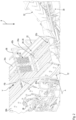
- FIG 1 is an inventive embodiment of a mobile machine of the present application generally designated 10.
- the machine 10 is a self-propelled screening system with a machine frame 12, which is carried by a crawler chassis 14 which is driven by a hydraulic motor 16.
- a power source for providing the energy required by the machine the machine has a power source that is accommodated in an engine compartment 18 Figure 1 Diesel internal combustion engine, not shown.
- a feed unit 20 is arranged, into which conveying vehicles separate from the machine 10, such as excavators or wheel loaders, or also a conveying device separate from the machine 10, such as a belt conveyor, bulk material, usually mineral bulk material , such as stone and/or concrete.
- the feed unit 20, which is a vibration conveyor device, conveys the bulk material entered into it to a feed longitudinal end 22a of a conveyor assembly 22 adjoining the feed unit 20.
- the conveyor assembly 22 is about a maintenance pivot axis WS relative to the machine frame 14 from its position in the Figures 1 , 2 and 4 shown working position in the working state of the machine 10 in the counterclockwise direction Figures 3 and 5 maintenance position shown in a maintenance state of the machine 10 and can be pivoted clockwise back into the working position.
- the maintenance pivot axis WS runs orthogonally to the conveyor track FB, to the height direction H explained below and to the direction of gravity g.
- the conveyor assembly 22 takes over the bulk material from the feed unit 20 at its feed longitudinal end 22a.
- the conveyor assembly 22 comprises a conveyor section 26 designed as a conveyor trough 24 with a bottom 24a designed as a sieve, in particular as a finger sieve, and with side cheeks 24b and 24c.
- a vibration motor 28 is shown on the outside of the side cheek 24b facing away from the floor 24a, which provides the vibration excitation for the conveyor assembly 22 forming a vibratory conveyor device.
- the conveyor assembly 22 conveys the bulk material transferred to it at the feed longitudinal end 22a along the virtual conveyor track FB on the conveyor section 26 to its opposite transfer longitudinal end 22b, the bulk material being separated into two fractions by the sieve during the movement along the conveyor track FB, namely into a coarser fraction , which cannot penetrate the openings of the finger sieve due to its grain size and therefore remains on the conveyor section 26, and into a finer fraction, which also passes through the openings of the finger sieve due to its grain size and reaches at least one further screening device located under the conveyor assembly 22.
- the screening devices are arranged above or below each other as so-called “screen decks” to save space.
- the coarser fraction is transferred at the longitudinal transfer end 22b from the conveyor assembly 22 to a first take-off conveyor device 30, which is designed, for example, as a belt conveyor device.
- the discharge conveyor 30 conveys the coarser fraction away from the machine 10 for further processing or storage.
- the machine 10 has a second discharge conveyor device 32, again exemplarily as a belt conveyor device, through which a coarser part of the finer fraction of the bulk material conveyed and sieved by the sieve conveyor assembly 22 is transported away from the machine 10 for further use.
- a second discharge conveyor device 32 again exemplarily as a belt conveyor device, through which a coarser part of the finer fraction of the bulk material conveyed and sieved by the sieve conveyor assembly 22 is transported away from the machine 10 for further use.
- the third take-off conveyor device 34 can be provided by one of the following Transfer conveyor device 54 located on the screen deck 52 (see Fig. Fig. 3 ), for example a belt conveyor device, can be fed.
- the transfer longitudinal end 22b is geodetically lower than the feed longitudinal end 22a, so that the conveying section 26 has a gradient along the conveying direction V, which supports the conveying of bulk material from the feed longitudinal end 22a to the transfer longitudinal end 22b.
- the feed unit 20 conveys the bulk material entered into it in the example shown against an incline, i.e. uphill.
- a component carrier 36 extends across the conveyor section 26.
- the height direction H is best seen in the side view of Fig. 4 to recognize.
- a chain curtain 40 hangs down from the component carrier 36 as a material brake in order to mechanically brake bulk material conveyed by the sieve conveyor assembly 22 through physical contact and to avoid excessively high conveying speeds. Because of the gradient of the conveyor section 26, the height direction H is inclined relative to the direction of gravity g.
- FIG 2 the half of the conveyor assembly 22 that is closer to the transfer longitudinal end 22b is shown enlarged.
- the component carrier 36 is on both sides of the conveyor assembly 22 via a carrier holder 42a and 42b as well as a linkage lever 44a and 44b (see Figures 3 , 4 and 5 ) pivotally articulated on the machine frame 12.
- the levers 44a and 44b are normally hidden by a portion of the machine frame 12 when viewed from the outside and are not visible.
- the machine frame 12 is partially cut so that the lever 44a is completely visible.
- the levers 44a and 44b are connected to piston rods 46a and 46b as output members of actuators 48a and 48b designed as hydraulically operated piston-cylinder assemblies, so that the piston rods can be extended and retracted 46a and 46b a pivoting movement of the levers 44a and 44b about their in the Figures 2 , 4 and 5 shown articulation axis A causes. More precisely, extending the piston rods 46a and 46b in the example shown causes the levers 44a and 44b to pivot clockwise when viewed Figures 4 and 5 . Retracting the piston rods 46a and 46b accordingly causes a pivoting movement of the levers 44a and 44b when viewed Figures 4 and 5 counterclockwise.
- the articulation axis A is parallel to the maintenance pivot axis WS, i.e. orthogonal to the conveyor track FB and to the direction of gravity g and to the height direction H.
- the articulation axis A is orthogonal to the drawing planes of Figures 4 and 5 .
- the construction of the lever 44a, the actuator 48a, and the carrier holder 42a on one side of the machine 10 is relative to a vertical longitudinal center plane of the machine 10 to the construction of the lever 44b, the actuator 48b, and the carrier holder 42b on the width direction of the machine 10 opposite other side of the machine 10 in mirror image.
- the levers 44a and 44b are coupled to the conveyor assembly 22 at the location marked B. Pushing out the piston rods 46a and 46b in the working state Figures 1 , 2 and 4 leads to a pivoting movement of the levers 44a and 44b when looking at the Figures 4 and 5 clockwise, whereby the transfer longitudinal end 22b of the conveyor assembly 22 is raised counterclockwise about the maintenance pivot axis WS. If necessary, a translational degree of freedom of movement can be provided at one of the locations A, B or on the pivot bearing around the maintenance pivot axis WS.
- the location "B" may be a straight line extending over at least a portion of the width of the conveyor assembly 22.
- the further sieve device 50 can be seen in a further sieve deck 52 located under the conveyor assembly 22 under the conveyor assembly 22 which has been raised into the maintenance position. Also visible is the transfer conveyor device 54, designed as a transfer belt, which passes through the sieve device 50 The finest fraction of the bulk material sieved by the machine 10 is conveyed to the extraction conveyor 34.
- the carrier holders 42a and 42b have a bend in their extension half closer to the lever 44a and 44b connected to them, through which the component carrier 36, compared to a straight, stretched design of the carrier holders 42a and 42b, in the working state of the machine 10 Longitudinal end 22a is shifted towards. This enables a collision-free relative mobility with respect to the component carrier 36, in particular an approachability, of the withdrawal conveyor device 32 to the conveyor assembly 22.
- the bend is preferably formed starting from the respective lever 44a or 44b in a range of 20% to 40% of the extension length of the carrier holder 42a and 42b between the respective lever 44a or 44b and the component carrier 36, particularly preferably in a range of 25 % to 40%.
- the bend angle is between 5° and 25°.
- the actuators 48a and 48b are common adjustment actuators of the conveyor assembly 22 and the component carrier 36 in the sense described above in the introduction to the description.
- the component carrier 36 is located along the conveyor path FB outside the extension area of the conveyor assembly 22.
- the component carrier 36 is located along the conveyor path FB in front of the conveyor assembly 22 and no longer above her.
- the component carrier 36 is located approximately in the extension area of the base 24a or the side cheeks 24b and 24c.
- the component carrier 36 Due to the firm physical-mechanical coupling of the component carrier 36 with the levers 44a and 44b, which also raise and lower the conveyor assembly 22, the component carrier 36 can be positioned in an extremely advantageous manner above the conveyor section 26 when the machine 10 is in the working state in an optimal position for the functional assembly carried by it be arranged, which does not exceed a transport silhouette.
- the conveyor assembly 22 can be moved between its operating positions: working position and maintenance position without fear of a collision with the component carrier 36, namely by the already existing actuator arrangement for raising and lowering the conveyor assembly 22, which also kinematically clearly adjusts the component carrier 36.
Landscapes
- Engineering & Computer Science (AREA)
- Mechanical Engineering (AREA)
- Structure Of Belt Conveyors (AREA)
- Jigging Conveyors (AREA)
- Framework For Endless Conveyors (AREA)
- Feeding Of Articles To Conveyors (AREA)
Description
- Die vorliegende Erfindung betrifft eine mobile, insbesondere selbstfahrende, Maschine gemäß dem Oberbegriff von Anspruch 1.
- Eine solche mobile Maschine in Gestalt einer mobilen Siebanlage ist aus der
US 2020/0384504 A1 bekannt. Die bekannte Maschine weist eine Aufgabeeinheit auf, die durch eine Fördereinrichtung oder durch ein Förderfahrzeug mit Schüttgut beschickt wird. Die Aufgabeeinheit übergibt Schüttgut an die Förderbaugruppe an einem Aufgabelängsende derselben, von wo aus die Förderbaugruppe das Schüttgut zu einem Übergabelängsende fördert, an welchem die Förderbaugruppe das auf der Förderstrecke verbliebene Schüttgut an wenigstens ein Abzugsband übergibt. Während der Vibrationsförderung längs der geradlinigen Förderbahn wird das Schüttgut durch ein am Boden der Förderbaugruppe ausgebildetes Sieb korngrößenabhängig getrennt. Die so erhaltenen Fraktionen werden unterschiedlichen Abzugsbändern zugeführt und von diesen zur weiteren Verarbeitung von der Siebanlage abtransportiert. - Die Förderstrecke ist rinnenartig ausgebildet und umfasst einen als Sieb ausgebildeten Boden, welcher beiderseits von Seitenwangen begrenzt ist, die eine körperliche Barriere für das auf der Förderstrecke befindliche Schüttgut bilden, sodass dieses nicht seitlich herunterfallen kann, sondern sich, abgesehen von einer Sortierbewegung beim Sieben, nur längs der Förderbahn bewegt.
- Die Förderbaugruppe mit der beschriebenen rinnenartigen Förderstrecke kann durch schwenken um eine näher bei dem Aufgabelängsende gelegene Wartungsschwenkachse zu Wartungszwecken relativ zum Maschinenrahmen angehoben werden.
- An den Seitenwangen der Förderstrecke sind starr mit den Seitenwangen verbunden Trägerhalter befestigt, welche nach oben über den Rand der Seitenwangen vorstehen. An ihren von den Seitenwangen fernliegenden Längsenden sind die Trägerhalter durch einen Komponententräger verbunden, welcher die Förderstrecke im Wesentlichen parallel zur Wartungsschwenkachse überspannt. Der Komponententräger trägt im Beispiel des Standes der Technik eine Materialbremse in Gestalt eines Vorhangs, welcher als mechanischer Bewegungswiderstand zu große Fördergeschwindigkeiten des Schüttguts auf der Förderstrecke verhindern soll.
- Dieser im dargestellten Beispiel des Stands der Technik die Förderstrecke brückenartig überspannende Komponententräger kann zu folgenden Problemen führen: die Förderbaugruppe bildet häufig als Sieb-Förderbaugruppe eine möglichst weit oben, also entfernt vom Aufstandsuntergrund der Maschine, am Maschinenrahmen angeordnete Baugruppe, sodass vom Sieb der Förderbaugruppe durchgelassene Korngrößenfraktionen schwerkraftgetrieben durch das Sieb, gegebenenfalls zur weiteren Sortierung in weitere Siebvorrichtungen, fallen können. Der Komponententräger kann dann soweit die Förderbaugruppe in Höhenrichtung überragen, dass der Komponententräger eine zulässige Transportsilhouette der Maschine nach oben überschreitet. Der Komponententräger muss dann zum Transport der Maschine abmontiert werden.
- Außerdem ist der an den Seitenwangen der Vibrationsförderbaugruppe festgelegte Komponententräger durch die Vibrationen der Förderbaugruppe belastet, sodass er entweder nur sehr robuste Funktionsbaugruppen tragen kann oder unter Zwischenanordnung einer aufwändigen Vibrationsentkopplung mit den Seitenwangen verbunden werden muss.
- Falls der Komponententräger über seine Trägerhalter nicht starr an der Förderbaugruppe selbst, sondern etwa am Maschinenrahmen befestigt wäre, würde der Komponententräger nicht mit der Förderbaugruppe mitbewegt und könnte deren Bewegung in eine relativ zum Maschinenrahmen angehobene Wartungsstellung behindern. Würde der Komponententräger in Höhenrichtung mit so großem Abstand von der Förderstrecke am Maschinenrahmen befestigt, dass er das Anheben der Förderbaugruppe nicht mehr behindern würde, bestünde erneut das zuvor geschilderte Problem des Überschreitens der Transportsilhouette. Außerdem kann der Komponententräger nicht beliebig weit über der Förderstrecke angeordnet werden, ohne dass dies die Funktionserfüllung der am Komponententräger angeordneten Funktionsbaugruppen beeinträchtigen würde.
- Aus der
US 3104037 A ist ein sich quer über eine Förderstrecke für Schüttgut erstreckender Komponententräger bekannt. Der Komponententräger trägt Ketten als mechanische Wirkkomponenten, welche vom Komponententräger auf das auf der Förderstrecke geförderte Schüttgut aufliegen. Mittels eines Exzenterantriebs ist der Komponententräger zu einer um seine Längsachse hin und her schwenkenden Bewegung antreibbar. - Weiter sei die
DE 10 2018 009 801 A1 genannt, welche eine Vorrichtung zum Trennen von Schutt offenbart. Die bekannte Vorrichtung weist ein umlaufendes Förderband zur Förderung des Schutts auf. Auf dem Obertrum des Förderbands aufliegender Schutt wird nacheinander in der genannten Reihenfolge an einem Rechen, einem auf das Förderband einwirkenden Verdichter-Rüttler und einer Blasdüse vorbeigeführt. - Ausgehend von dem oben Gesagten ist es Aufgabe der vorliegenden Erfindung, die eingangs genannte Maschine derart weiterzubilden, dass sich der Komponententräger im Arbeitszustand der Maschine an einem Ort über der Förderstrecke befindet, welcher für die von ihm getragene wenigstens eine Funktionsbaugruppe möglichst optimal ist. Dabei soll der Komponententräger für Transport oder/und Wartung der übrigen Maschine bzw. der Förderbaugruppe keinen übermäßigen Montageaufwand erzeugen.
- Die vorliegende Erfindung löst diese Aufgabe durch eine Maschine mit allen Merkmalen des Anspruchs 1. Dabei ist der Komponententräger sowohl relativ zur Förderbaugruppe als auch relativ zum Maschinenrahmen beweglich an der mobilen Maschine angeordnet. Im Gegensatz zum Komponententräger der aus der
US 2020/0384504 A1 bekannten Maschine, welcher gemeinsam mit der Förderbaugruppe relativ zum Maschinenträger beweglich, jedoch relativ zu der ihn tragenden Förderbaugruppe unbeweglich ist, ist die Beweglichkeit des Komponententrägers der vorliegend diskutierten Maschine erhöht. Mit seiner Beweglichkeit sowohl relativ zur Förderbaugruppe als auch relativ zum Maschinenrahmen kann der Komponententräger auf einfache Art und Weise zwischen einer optimalen Arbeitsstellung, in welcher er sich im Arbeitszustand der Maschine befindet, und einer Wartungsstellung, in welcher er sich beispielsweise bei relativ zum Maschinenrahmen angehobener Förderbaugruppe befindet, bewegt werden. Die hierfür notwendige Kinematik des Komponententrägers kann auf Grundlage des Bewegungsraums der Förderbaugruppe relativ zum Maschinenrahmen und der gewünschten Endpositionen einer Bewegung des Komponententrägers einfach ermittelt und an der Maschine realisiert werden. - Grundsätzlich kann der Komponententräger beliebig relativ zum Maschinenrahmen beweglich sein, beispielsweise translatorisch verschiebbar. Aufgrund der häufig durch mineralischen Staub belasteten Arbeitsumgebung des Komponententrägers ist der Komponententräger bevorzugt schwenkbeweglich. Eine Schwenklagerung nimmt weniger Bauraum ein als eine translatorische Bewegungsführung und ist daher mit geringerem Aufwand besser gegenüber einer staubbelasteten Umgebung abschirmbar als etwa eine Linearführung. Zur Sicherstellung der zuvor genannten Relativbeweglichkeit ist der Komponententräger bevorzugt relativ zum Maschinenrahmen um eine Schwenkachse schwenkbeweglich am Maschinenrahmen angeordnet.
- Grundsätzlich kann die Förderbaugruppe eine beliebige Baugruppe sein, welche zur Förderung von Schüttgut geeignet ist. Die Förderbaugruppe kann beispielsweise einen Bandförderer mit einem endlos umlaufenden Förderband umfassen, dessen Obertrum darauf aufliegendes Schüttgut längs des Verlaufs des Obertrums fördert. Bevorzugt umfasst die Förderbaugruppe, wie jene des Standes der Technik, einen Vibrationsförderer, besonders bevorzugt mit einer längs der Förderbahn verlaufenden Förderrinne. Wenngleich die Förderbahn krummlinig, etwa wendelförmig verlaufen kann, so ist sie bevorzugt geradlinig.
- Weiter bevorzugt erfüllt die Förderbaugruppe neben der Förderung von Schüttgut längs der Förderbahn weitere Funktionen. Gemäß einer bevorzugten Weiterbildung der vorliegenden Erfindung weist die Förderstrecke ein Sieb auf, ist also auch eine Siebstrecke, längs welcher das Schüttgut korngrößenabhängig getrennt wird. Die bevorzugt vorgesehene Förderrinne kann daher durch eine wenigstens abschnittsweise Ausbildung ihres Bodens als Sieb als Sieb-Förderrinne ausgestaltet sein.
- Die Förderbaugruppe und die Funktionsbaugruppe am Komponententräger müssen nicht die einzigen Arbeitsbaugruppen der mobilen Maschine sein, wenngleich dies nicht ausgeschlossen sein soll. Die Maschine kann neben der genannten Förderbaugruppe wenigstens eine weitere Fördervorrichtung, insbesondere einen Bandförderer, oder/und wenigstens eine weitere Siebvorrichtung zur weiteren Sortierung des Schüttguts oder/und eine Brecherbaugruppe, etwa einen Kegelbrecher oder/und einen Backenbrecher oder/und einen Prallbrecher, zur Zerkleinerung von wenigstens Teilen des in die Maschine aufgegebenen Schüttguts aufweisen.
- Besonders bevorzugt ist die Maschine eine mobile, insbesondere selbstfahrende, Siebanlage mit einer Aufgabeeinheit zur Aufnahme von Schüttgut von außerhalb der Maschine und zur Förderung des Schüttguts zum Aufgabelängsende der oben genannten Sieb-Förderbaugruppe. Die Sieb-Förderbaugruppe fördert das Schüttgut zu seinem entgegengesetzten Übergabelängsende, wo es die auf der Sieb-Förderstrecke verbliebene gröbere Fraktion des geförderten Schüttguts an eine Abzugsfördervorrichtung, insbesondere an ein Abzugsband, übergibt. Die während der Förderung zum Übergabelängsende von der Sieb-Förderstrecke durch deren Sieböffnungen durchgelassene feinere Fraktion kann durch eine weitere Abzugsfördervorrichtung, insbesondere durch ein weiteres Abzugsband, von der Siebanlage weggefördert werden, oder die feinere Fraktion kann durch wenigstens eine weitere Siebvorrichtung korngrößenabhängig in weitere Fraktionen getrennt werden.
- Die wenigstens eine weitere Siebvorrichtung befindet sich aus Gründen möglichst kompakten Bauraums bevorzugt unter der Sieb-Förderbaugruppe, sodass die von der Sieb-Förderstrecke durchgelassene feinere Fraktion schwerkraftgetrieben zur weiteren Siebvorrichtung gelangen kann.
- Die mobile Maschine umfasst zur Bereitstellung von Arbeitsenergie eine Kraftquelle, bevorzugt eine Brennkraftmaschine, besonders bevorzugt einen Dieselmotor. Als bevorzugte selbstfahrende Maschine weist sie ein Fahrwerk und wenigstens einen Antriebsmotor auf. Der Antriebsmotor kann ein Hydraulikmotor sein. Der notwendige Hydraulikdruck wird durch die Kraftquelle bereitgestellt. Wenngleich das Fahrwerk ein Räderfahrwerk sein kann oder wenigstens ein Rad aufweisen kann, ist wegen der höheren Tragfähigkeit bei gleichem Bauraum und dem in der Regel nur grob texturierten Aufstandsuntergrund der Maschine im Arbeitseinsatz ein Raupenfahrwerk als Fahrwerk bevorzugt. Das Fahrwerk trägt den Maschinenrahmen über dem Aufstandsuntergrund der Maschine.
- Zur Entlastung des an der Maschine arbeitenden Personals und zur Sicherstellung der Verstellbarkeit des Komponententrägers weist die mobile Maschine erfindungsgemäß einen Verstellaktuator auf, welcher mit dem Komponententräger derart Bewegung und Kraft übertragend gekoppelt ist, dass der Komponententräger durch den Verstellaktuator zu einer Verstellbewegung relativ zum Maschinenrahmen und auch relativ zur Förderbaugruppe antreibbar ist. Erfindungsgemäß ist der Verstellaktuator auch mit der Förderbaugruppe derart Bewegung und Kraft übertragend gekoppelt, dass auch die Förderbaugruppe durch den Verstellaktuator zu einer Verlagerungsbewegung relativ zum Maschinenrahmen antreibbar ist.
- Wenngleich es im Rahmen der vorliegenden Erfindung vorstellbar ist, dass ein und derselbe Verstellaktuator den Komponententräger und die Förderbaugruppe nacheinander bewegt, ist es zur Verkürzung der Rüst- oder/und Wartungszeiten der Maschine vorteilhaft, wenn sich die durch den Verstellaktuator bewirkten Bewegungen von Komponententräger und Förderbaugruppe wenigstens zeitlich überlappen. Hierzu ist bevorzugt vorgesehen, dass ein Ausgangsglied des Verstellaktuators mit einem Gestänge oder Getriebe gekoppelt ist, welches sowohl mit der Förderbaugruppe als auch mit dem Komponententräger Bewegung und Kraft übertragend gekoppelt ist, so dass wenigstens während eines Zeitabschnitts eines Bewegungsbetriebs des Verstellaktuators gleichzeitig sowohl die Förderbaugruppe als auch der Komponententräger verlagert wird. Bevorzugt werden die Förderbaugruppe und der Komponententräger über wenigstens 50 %, besonders bevorzugt über wenigstens 80 % der Bewegungsdauer der Förderbaugruppe gemeinsam und gleichzeitig bewegt.
- Der Verstellaktuator kann ein beliebiger Aktuator sein, beispielsweise ein Elektromotor oder ein pneumatischer Aktuator, etwa eine Kolben-Zylinder-Anordnung. Wegen der auf den eingeforderten Bauraum bezogenen vorteilhaft hohen Verstellkraft ist ein hydraulischer Aktuator, insbesondere eine hydraulische Kolben-Zylinder-Anordnung, als der Aktuator bevorzugt.
- Für die Erläuterungen der Maschine in der vorliegenden Anmeldung soll die Maschine auf einem Bezugsuntergrund aufgestellt gedacht sein, das ist in diesem Falle ein ebener horizontaler, zur Schwerkraftwirkungsrichtung orthogonaler Aufstandsuntergrund. Die Förderbaugruppe ist mit einer in Höhenrichtung verlaufenden Verlagerungskomponente relativ zum Maschinenrahmen verlagerbar. Bei parallel zum Bezugsuntergrund verlaufender Förderstrecke ist die Höhenrichtung parallel zur Schwerkraftwirkungsrichtung. Dann, wenn die Förderstrecke relativ zum Bezugsuntergrund um einen Neigungswinkel geneigt ist, was in der Regel der Fall ist, denn die virtuelle Förderbahn verläuft in Richtung zum Übergabelängsende hin bevorzugt zum Aufstandsuntergrund hin, ist die Höhenrichtung um denselben Neigungswinkel zur Schwerkraftwirkungsrichtung geneigt. Die Höhenrichtung verläuft jedoch überwiegend längs der Schwerkraftwirkungsrichtung und ist gegenüber dieser in der Regel um weniger als 45° geneigt. Die Förderbaugruppe ist daher auch mit einer längs der Schwerkraftwirkungsrichtung verlaufenden Verlagerungskomponente relativ zum Maschinenrahmen verlagerbar.
- Die Förderbaugruppe kann relativ zum Maschinenrahmen translatorisch verlagerbar sein. Bevorzugt ist sie um eine Wartungsschwenkachse schwenkbar, wobei die Förderbaugruppe besonders bevorzugt im Bereich ihres Aufgabelängsendes um die Wartungsschwenkachse schwenkbar am Maschinenrahmen angelenkt ist. Die Wartungsschwenkachse verläuft bevorzugt außerhalb der Förderstrecke in einem dem Aufgabelängsende näher als dem Übergabelängsende gelegenen Erstreckungsbereich der Förderbaugruppe.
- Auch eine kombinierte translatorische und rotatorische Verlagerbarkeit der Förderbaugruppe relativ zum Maschinenrahmen ist denkbar, falls die Kinematik des Gestänges oder Getriebes dies erfordert. Jedoch ist die bloße Schwenkbarkeit aufgrund der Robustheit der für ihre Realisierung erforderlichen konstruktiven Maßnahmen an der Maschine bevorzugt. Dies bedeutet, dass bevorzugt das dem Aufgabelängsende längs der Förderbahn entgegengesetzte Übergabelängsende der Förderbaugruppe den längsten Verlagerungsweg aller Orte der Förderbaugruppe relativ zum Maschinenrahmen aufweist. Bevorzugt ist der Komponententräger im Arbeitszustand der Maschine dem Übergabelängsende näher gelegen als dem Aufgabelängsende.
- Grundsätzlich kann das Gestänge oder Getriebe ein Rädergetriebe aufweisen. Zur Erzielung großer Verlagerung- und Verstellwege mit möglichst wenig Bauteilen umfasst das Gestänge oder Getriebe bevorzugt einen Hebel, welcher einen Anlenkabschnitt aufweist, in dem er um eine Anlenkachse schwenkbar am Maschinenrahmen angelenkt ist, und welcher einen Kopplungsabschnitt aufweist, in dem er mit der Förderbaugruppe gekoppelt ist. Die Kopplung mit der Förderbaugruppe kann eine gleitende Kopplung sein, sodass sich bei Betätigung des Hebels durch den Verstellaktuator der Kopplungsort des Hebels mit der Förderbaugruppe verändert, insbesondere an der Förderbaugruppe wandert. Gerade bei der bevorzugten Verwendung einer Kolben-Zylinder-Anordnung als der Verstellaktuator kann der Hebel den Hub des Verstellaktuators effektiv verlängern, sodass ein vorteilhaft kurzer Verstellaktuator eingesetzt werden kann.
- Wenngleich der Komponententräger, bevorzugt über wenigstens einen seitlichen Trägerhalter, wiederum mit dem Hebel durch ein weiteres Gestänge oder/und ein weiteres Getriebe relativbeweglich verbunden sein kann, ist der Komponententräger aus Gründen einer möglichst robusten Konstruktion mit möglichst wenigen Bauteilen, bevorzugt starr mit dem Hebel zur gemeinsamen Schwenkbewegung um die Anlenkachse als der Schwenkachse des Komponententrägers verbunden.
- Die Schwenkachse des Komponententrägers verläuft bevorzugt orthogonal zur Förderbahn oder/und orthogonal zur Höhenrichtung und ebenso bevorzugt parallel zum Bezugsuntergrund. Bevorzugt sind daher die Schwenkachse des Komponententrägers und die Wartungsschwenkachse der Förderbaugruppe zueinander parallel.
- Folglich kann die mobile Maschine durch Relativbewegung der Förderbaugruppe relativ zum Maschinenrahmen mit der Bewegungskomponente in Höhenrichtung in einen vom Arbeitszustand verschiedenen Wartungszustand gebracht werden. In diesem Wartungszustand kann der Komponententräger in einem Bereich angeordnet sein, welcher sich nicht mehr über der Förderstrecke befindet, sondern längs der Förderbahn außerhalb des Erstreckungsbereichs der Förderstrecke gelegen ist. Somit kann der Komponententräger eine Bewegung der Förderbaugruppe vom Maschinenrahmen weg und eine Wartung der Förderbaugruppe von oben nicht behindern.
- Der Komponententräger kann die Förderstrecke brückenartig überspannen, was eine stabile Lagerung des Komponententrägers an Trägerhaltern beiderseits der Förderstrecke ermöglicht. Alternativ kann der Komponententräger galgenartig nur auf einer Seite der Förderstrecke durch einen Trägerhalter mit dem Maschinenrahmen verbunden sein und auskragend von dem Trägerhalter über die Förderstrecke einragen. Die galgenartige Anordnung des Komponententrägers ist zwar weniger stabil als die brückenartige, ermöglicht jedoch auf jener Seite der Förderstrecke, auf welcher kein Trägerhalter angeordnet ist, eine etwaig vorhandene Fördervorrichtung, etwa ein Abzugsband ungehindert über die Förderbaugruppe bewegen zu können.
- Zu demselben Zweck kann der wenigstens eine Trägerhalter in seinem Verlauf von seinem Anlenkort am Maschinenrahmen bzw. an dem Hebel des Gestänges oder/und Getriebes zum Komponententräger um eine zur Schwenkachse des Komponententrägers vorzugsweise parallele Krümmungs- bzw. Knickachse gekrümmt oder/und geknickt ausgeführt sein. Auch hierdurch kann Raum zur kollisionsfreien Anordnung einer Fördervorrichtung relativ zum Komponententräger geschaffen werden. Ein Knick ist vorzugsweise in der dem Anbringungsort am Maschinenrahmen bzw. am Hebel nähergelegenen Hälfte des wenigstens einen Trägerhalters angeordnet. Dann kann der Knickwinkel vergleichsweise gering ausfallen und trotzdem eine nennenswerte Veränderung der Position des Komponententrägers, verglichen mit einem geradlinigen Trägerhalter, erreicht werden. Der Knickwinkel kann beispielsweise zwischen 5° und 25° betragen.
- Die wenigstens eine Funktionsbaugruppe am Komponententräger kann eine Materialbremse sein, welche als Vorhang, beispielsweise als Ketten- oder Lappenvorhang in Richtung zur Förderstrecke vom Komponententräger herabhängt und auf der Förderstrecke gefördertes Schüttgut berührt und so mechanisch abbremst. Die Funktionsbaugruppe kann zusätzlich oder alternativ eine Sprühvorrichtung sein, welche zur Verringerung der Staubentwicklung über der Förderstrecke Flüssigkeit, vorzugsweise Wasser, zur Förderstrecke ausbringt, sei es als Sprühnebel, als Beregnung oder als Schwallschüttung. In diesem Fall steht die Funktionsbaugruppe in strömungsmechanischem Wirkzusammenhang mit dem Schüttgut.
- Die Funktionsbaugruppe am Komponententräger kann zusätzlich oder alternativ eine Beleuchtungsvorrichtung sein, welche die Förderstrecke beleuchtet, oder kann eine Kamera sein, welche die Förderstrecke im sichtbaren Wellenlängenbereich oder/und im Infrarotbereich erfasst und die erfasste Information zu einem Maschinenführer überträgt. Dann steht die Funktionsbaugruppe strahlungstechnisch im Wirkzusammenhang mit dem Schüttgut bzw. der Förderstrecke.
- Weiter zusätzlich oder alternativ kann die Funktionsbaugruppe ein Mikrofon oder einen Ultraschallsensor aufweisen, welcher die Förderstrecke und darauf gefördertes Schüttgut akustisch erfasst.
- Die vorliegende Erfindung wird nachfolgend anhand der beiliegenden Zeichnungen näher erläutert. Es stellt dar:
- Fig. 1
- eine schematische perspektivische Ansicht einer erfindungsgemäßen selbstfahrenden Maschine in Gestalt einer Siebanlage im Arbeitszustand,
- Fig. 2
- eine schematische perspektivische vergrößerte Ansicht des Bereichs des Übergabelängsendes der Förderbaugruppe der Maschine von
Fig. 1 im Arbeitszustand, - Fig. 3
- eine schematische perspektivische vergrößerte Ansicht des Bereichs des Übergabelängsendes der Förderbaugruppe der Maschine von
Fig. 1 im Wartungszustand mit angehobener Förderbaugruppe, - Fig. 4
- eine schematische Seitenansicht des Bereichs des Übergabelängsendes der Förderbaugruppe der Maschine von
Fig. 1 im Arbeitszustand, und - Fig. 5
- eine schematische Seitenansicht des Bereichs des Übergabelängsendes der Förderbaugruppe der Maschine von
Fig. 1 im Wartungszustand. - In
Figur 1 ist eine erfindungsgemäße Ausführungsform einer mobilen Maschine der vorliegenden Anmeldung allgemein mit 10 bezeichnet. Die Maschine 10 ist eine selbstfahrende Siebanlage mit einem Maschinenrahmen 12, welcher von einem Raupenfahrwerk 14 getragen ist, das durch einen Hydromotor 16 angetrieben ist. Die Maschine weist als Kraftquelle zur Bereitstellung der an der Maschine benötigten Energie eine in einem Motorraum 18 aufgenommene, inFigur 1 nicht dargestellte Diesel-Brennkraftmaschine auf. - Über dem Motorraum 18 ist im Arbeitszustand der Maschine 10 eine Aufgabeeinheit 20 angeordnet, in welche von der Maschine 10 gesonderte Förderfahrzeuge, wie beispielsweise Bagger oder Radlader, oder auch eine von der Maschine 10 gesonderte Fördervorrichtung, wie Bandförderer, Schüttgut, in der Regel mineralisches Schüttgut, wie Stein oder/und Beton, eingeben. Die Aufgabeeinheit 20, die eine Vibrationsfördervorrichtung ist, fördert das in sie eingegebene Schüttgut zu einem Aufgabelängsende 22a einer an die Aufgabeeinheit 20 anschließenden Förderbaugruppe 22. Die Förderbaugruppe 22 ist um eine Wartungsschwenkachse WS relativ zum Maschinenrahmen 14 von ihrer in den
Figuren 1 ,2 und4 gezeigten Arbeitsstellung im Arbeitszustand der Maschine 10 im Gegenuhrzeigersinn in ihre in denFiguren 3 und5 gezeigte Wartungsstellung in einem Wartungszustand der Maschine 10 und im Uhrzeigersinn wieder zurück in die Arbeitsstellung schwenkbar. Die Wartungsschwenkachse WS verläuft orthogonal zur Förderbahn FB, zur weiter unten erläuterten Höhenrichtung H und zur Schwerkraftwirkungsrichtung g. - Die Förderbaugruppe 22 übernimmt an ihrem Aufgabelängsende 22a das Schüttgut von der Aufgabeeinheit 20. Die Förderbaugruppe 22 umfasst eine als Förderrinne 24 ausgebildete Förderstrecke 26 mit einem als Sieb, insbesondere als Fingersieb, ausgebildeten Boden 24a und mit Seitenwangen 24b und 24c. An der vom Boden 24a weg weisenden Außenseite der Seitenwange 24b ist ein Vibrationsmotor 28 dargestellt, welcher die Vibrationsanregung für die eine Vibrationsfördervorrichtung bildende Förderbaugruppe 22 liefert.
- Die Förderbaugruppe 22 fördert das ihr am Aufgabelängsende 22a übergebene Schüttgut längs der virtuellen Förderbahn FB auf der Förderstrecke 26 zu ihrem entgegengesetzten Übergabelängsende 22b, wobei das Schüttgut während der Bewegung längs der Förderbahn FB durch das Sieb in zwei Fraktionen getrennt wird, nämlich in eine gröbere Fraktion, welche aufgrund ihrer Korngröße die Öffnungen des Fingersiebs nicht durchdringen kann und deshalb auf der Förderstrecke 26 verbleibt, und in eine feinere Fraktion, welche ebenfalls aufgrund ihrer Korngröße durch die Öffnungen des Fingersiebs hindurch gelangt und wenigstens eine weitere unter der Förderbaugruppe 22 gelegene Siebvorrichtung erreicht. Die Siebvorrichtungen sind als sogenannte "Siebdecks" bauraumsparend über- bzw. untereinander angeordnet.
- Die gröbere Fraktion wird am Übergabelängsende 22b von der Förderbaugruppe 22 an eine beispielhaft als Bandfördervorrichtung ausgestaltete erste Abzugsfördervorrichtung 30 übergeben. Die Abzugsfördervorrichtung 30 fördert die gröbere Fraktion von der Maschine 10 weg zur weiteren Verarbeitung oder Lagerung.
- Die Maschine 10 weist in dem dargestellten Beispiel eine zweite Abzugsfördervorrichtung 32 auf, wiederum beispielhaft als Bandfördervorrichtung, durch welche ein wiederum gröberer Teil der feineren Fraktion des von der Sieb-Förderbaugruppe 22 geförderten und gesiebten Schüttguts von der Maschine 10 zur weiteren Verwendung weg transportiert wird.
- Eine näher am Aufgabelängsende 22a der Förderbaugruppe 22 gelegene dritte Abzugsfördervorrichtung 34, wiederum in Gestalt eines Abzugsbandes, kann den feineren Teil der feineren Fraktion des von der Sieb-Förderbaugruppe 22 geförderten und gesiebten Schüttguts nach einem erneuten Sieben durch das unter der Sieb-Förderbaugruppe 22 gelegene weitere Siebdeck 52 (s.
Fig. 3 ) von der Maschine 10 weg transportieren. Die dritte Abzugsfördervorrichtung 34 kann durch ein unter dem weiteren Siebdeck 52 gelegene Transferfördervorrichtung 54 (s.Fig. 3 ), beispielsweise wiederum eine Bandfördervorrichtung, beschickt werden. - In dem in
Figur 1 gezeigten Arbeitszustand der Maschine 10 liegt das Übergabelängsende 22b geodätisch tiefer als das Aufgabelängsende 22a, sodass die Förderstrecke 26 längs der Förderrichtung V ein Gefälle aufweist, welches die Förderung von Schüttgut vom Aufgabelängsende 22a zum Übergabelängsende 22b unterstützt. - Lediglich der Vollständigkeit wegen sei angemerkt, dass die Aufgabeeinheit 20 das in sie eingegebene Schüttgut im dargestellten Beispiel gegen eine Steigung, also bergauf, fördert.
- Mit Abstand längs einer zum Boden 24a orthogonalen Höhenrichtung H erstreckt sich ein Komponententräger 36 quer über die Förderstrecke 26. Die Höhenrichtung H ist am besten in der Seitenansicht von
Fig. 4 zu erkennen. Von dem Komponententräger 36 hängt als eine mögliche Funktionsbaugruppe 38 ein Kettenvorhang 40 als Materialbremse herab, um von der Sieb-Förderbaugruppe 22 gefördertes Schüttgut durch körperlichen Kontakt mechanisch abzubremsen und zu hohe Fördergeschwindigkeiten zu vermeiden. Wegen des Gefälles der Förderstrecke 26 ist die Höhenrichtung H gegenüber der Schwerkraftwirkungsrichtung g geneigt. - In
Figur 2 ist die dem Übergabelängsende 22b nähergelegene Hälfte der Förderbaugruppe 22 vergrößert dargestellt. Der Komponententräger 36 ist beiderseits der Förderbaugruppe 22 über je einen Trägerhalter 42a und 42b sowie über je einen Gestänge-Hebel 44a bzw. 44b (sieheFiguren 3 ,4 und5 ) schwenkbar am Maschinenrahmen 12 angelenkt. Die Hebel 44a und 44b sind normalerweise bei Betrachtung von außen durch einen Abschnitt des Maschinenrahmens 12 verdeckt und nicht sichtbar. In denFiguren 4 und5 ist der Maschinenrahmen 12 teilweise geschnitten, sodass der Hebel 44a vollständig sichtbar ist. - Die Hebel 44a und 44b sind mit Kolbenstangen 46a bzw. 46b als Ausgabeglieder von als hydraulisch betätigte Kolben-Zylinder-Anordnungen ausgebildeten Aktuatoren 48a bzw. 48b verbunden, sodass ein Ausfahren und ein Einziehen der Kolbenstangen 46a und 46b eine Schwenkbewegung der Hebel 44a bzw. 44b um ihre in den
Figuren 2 ,4 und5 gezeigte Anlenkachse A bewirkt. Genauer bewirkt ein Ausfahren der Kolbenstangen 46a und 46b im dargestellten Beispiel eine Schwenkbewegung der Hebel 44a bzw. 44b im Uhrzeigersinn bei Betrachtung derFiguren 4 und5 . Ein Einziehen der Kolbenstangen 46a und 46b bewirkt dementsprechend eine Schwenkbewegung der Hebel 44a bzw. 44b bei Betrachtung derFiguren 4 und5 im Gegenuhrzeigersinn. Die Anlenkachse A ist im dargestellten Beispiel parallel zur Wartungsschwenkachse WS, also orthogonal zur Förderbahn FB und zur Schwerkraftwirkungsrichtung g sowie zur Höhenrichtung H. Die Anlenkachse A ist orthogonal zu den Zeichenebenen derFiguren 4 und5 . - Die Konstruktion des Hebels 44a, des Aktuators 48a, und des Trägerhalters 42a auf der einen Seite der Maschine 10 ist bezüglich einer vertikalen Längsmittelebene der Maschine 10 zur Konstruktion des Hebels 44b, des Aktuators 48b, und des Trägerhalters 42b auf der in Breitenrichtung der Maschine 10 entgegengesetzten anderen Seite der Maschine 10 spiegelbildlich.
- Die Hebel 44a und 44b sind an dem mit B gekennzeichneten Ort mit der Förderbaugruppe 22 gekoppelt. Ein Ausschieben der Kolbenstangen 46a und 46b im Arbeitszustand der
Figuren 1 ,2 und4 führt zu einer Schwenkbewegung der Hebel 44a und 44b bei Betrachtung derFiguren 4 und5 im Uhrzeigersinn, wodurch das Übergabelängsende 22b der Förderbaugruppe 22 im Gegenuhrzeigersinn um die Wartungsschwenkachse WS angehoben wird. Erforderlichenfalls kann an einem der Orte A, B oder an der Schwenklagerung um die Wartungsschwenkachse WS ein translatorischer Bewegungsfreiheitsgrad vorgesehen sein. Der Ort "B" kann eine sich über wenigstens einen Teil der Breite der Förderbaugruppe 22 erstreckende Gerade sein. - In
Figur 3 ist unter der in die Wartungsstellung angehobenen Förderbaugruppe 22 die weitere Siebvorrichtung 50 in einem unter der Förderbaugruppe 22 gelegenen weiteren Siebdeck 52 erkennbar. Ebenfalls erkennbar ist die Transferfördervorrichtung 54, ausgebildet als Transferband, welche die von der Siebvorrichtung 50 durchgelassene feinste Fraktion des von der Maschine 10 gesiebten Schüttguts zur Abzugsfördervorrichtung 34 fördert. - Die Trägerhalter 42a und 42b weisen in ihrer dem jeweils mit ihnen verbundenen Hebel 44a bzw. 44b näher gelegenen Erstreckungshälfte einen Knick auf, durch welchen der Komponententräger 36, verglichen mit einer geradlinigen, gestreckten Ausbildung der Trägerhalter 42a und 42b, im Arbeitszustand der Maschine 10 zum Aufgabelängsende 22a hin verlagert ist. Hierdurch wird eine bezüglich des Komponententrägers 36 kollisionsfreie Relativbeweglichkeit, insbesondere eine Annäherbarkeit, der Abzugsfördervorrichtung 32 an die Förderbaugruppe 22 ermöglicht.
- Bevorzugt ist der Knick ausgehend von dem jeweiligen Hebel 44a bzw. 44b in einem Bereich von 20 % bis 40 % der Erstreckungslänge des Trägerhalters 42a und 42b zwischen dem jeweiligen Hebel 44a bzw. 44b und dem Komponententräger 36 ausgebildet, besonders bevorzugt in einem Bereich von 25 % bis 40 %. Der Knickwinkel beträgt zwischen 5° und 25°.
- Durch die starre Kopplung des Komponententrägers 36 über die Trägerhalter 42a und 42b mit den jeweiligen Hebeln 44a bzw. 44b wird der Komponententräger 36 dann, wenn die Förderbaugruppe 22 durch die Aktuatoren 48a und 48b in seine Wartungsstellung angehoben wird, gleichzeitig zum Übergabelängsende 22b und darüber hinaus verschwenkt. Die Aktuatoren 48a und 48b sind gemeinsame Verstellaktuatoren der Förderbaugruppe 22 und des Komponententrägers 36 im oben in der Beschreibungseinleitung beschriebenen Sinne.
- Wie insbesondere die Seitenansicht von
Figur 5 zeigt, befindet sich der Komponententräger 36 dann, wenn sich die Maschine 10 in ihrem Wartungszustand mit angehobener Förderbaugruppe 22 befindet, längs der Förderbahn FB außerhalb des Erstreckungsbereichs der Förderbaugruppe 22. Im dargestellten Beispiel befindet sich der Komponententräger 36 längs der Förderbahn FB vor der Förderbaugruppe 22 und nicht mehr über ihr. In Höhenrichtung H befindet sich der Komponententräger 36 etwa im Erstreckungsbereich des Bodens 24a oder der Seitenwangen 24b und 24c. Durch die feste körperlich-mechanische Kopplung des Komponententrägers 36 mit den auch die Förderbaugruppe 22 hebenden und senkenden Hebeln 44a und 44b kann in äußerst vorteilhafter Weise der Komponententräger 36 im Arbeitszustand der Maschine 10 in einer für die von ihm getragene Funktionsbaugruppe optimalen Position über der Förderstrecke 26 angeordnet sein, welche eine Transportsilhouette nicht überschreitet. Gleichzeitig kann die Förderbaugruppe 22 ohne Besorgnis einer Kollision mit dem Komponententräger 36 zwischen ihren Betriebsstellungen: Arbeitsstellung und Wartungsstellung, bewegt werden, und zwar durch die ohnehin vorhandene Aktuatoranordnung zum Heben und Senken der Förderbaugruppe 22, welche auch den Komponententräger 36 kinematisch eindeutig verstellt. - Durch die Anlenkung der Kolbenstangen 46a und 46b an den Hebeln 44a bzw. 44b zwischen der Anlenkachse A und dem Kopplungsort B wird der Hubweg der Kolbenstangen 46a und 46b übersetzt und die Hubkraft untersetzt.
Claims (11)
- Mobile Maschine (10) zur Förderung von mineralischem Schüttgut, umfassend einen Maschinenrahmen (12) und eine am Maschinenrahmen (12) relativ zu diesem verlagerbar gelagerte Förderbaugruppe (22), welche eine längs einer virtuellen Förderbahn (FB) verlaufende Förderstrecke (26) umfasst, wobei die Förderbaugruppe (22) wenigstens zur Förderung des Schüttguts längs der Förderbahn (FB) auf der Förderstrecke (26) ausgebildet ist, wobei die Maschine (10) einen Komponententräger (36) aufweist, welcher in einem zu wenigstens einer Handlung aus Förderung und Verarbeitung von Schüttgut betriebsbereiten Arbeitszustand der Maschine (10) in einer Höhenrichtung (H) mit Abstand von der Förderstrecke (26) quer zur Förderbahn (FB) über der Förderstrecke (26) verläuft, wobei der Komponententräger (36) wenigstens eine Funktionsbaugruppe (38) trägt, welche in wenigstens einem Wirkzusammenhang aus einem mechanischen und einem strömungsmechanischen und einem strahlungstechnischen und einem akustischen Wirkzusammenhang mit auf der Förderstrecke (26) gefördertem Schüttgut steht, wobei die Förderbaugruppe (22) mit einer Verlagerungskomponente in Höhenrichtung (H) relativ zum Maschinenrahmen (12) verlagerbar ist, dadurch gekennzeichnet, dass die mobile Maschine (10) einen Verstellaktuator (48a, 48b) aufweist, welcher mit dem Komponententräger (36) derart Bewegung und Kraft übertragend gekoppelt ist, dass der Komponententräger (36) durch den Verstellaktuator (48a, 48b) zu einer Verstellbewegung relativ zum Maschinenrahmen (12) antreibbar ist, wobei der Komponententräger (36) sowohl relativ zur Förderbaugruppe (22) als auch relativ zum Maschinenrahmen (12) beweglich an der mobilen Maschine (10) angeordnet ist, wobei der Verstellaktuator (48a, 48b) auch mit der Förderbaugruppe (22) derart Bewegung und Kraft übertragend gekoppelt ist, dass auch die Förderbaugruppe (22) durch den Verstellaktuator (48a, 48b) zu einer Verlagerungsbewegung relativ zum Maschinenrahmen (12) antreibbar ist.
- Mobile Maschine (10) nach Anspruch 1,
dadurch gekennzeichnet, dass der Komponententräger (36) relativ zum Maschinenrahmen (12) um eine Schwenkachse (A) schwenkbeweglich am Maschinenrahmen (12) angeordnet ist. - Mobile Maschine (10) nach Anspruch 1 oder 2,
dadurch gekennzeichnet, dass ein Ausgangsglied (46a, 46b) des Verstellaktuators (48a, 48b) mit einem Gestänge oder Getriebe gekoppelt ist, welches sowohl mit der Förderbaugruppe (22) als auch mit dem Komponententräger (36) Bewegung und Kraft übertragend gekoppelt ist, so dass wenigstens während eines Zeitabschnitts eines Bewegungsbetriebs des Verstellaktuators (48a, 48b) gleichzeitig sowohl die Förderbaugruppe (22) als auch der Komponententräger (36) verlagert wird. - Mobile Maschine (10) nach Anspruch 3,
dadurch gekennzeichnet, dass das Gestänge oder Getriebe einen Hebel (44a, 44b) umfasst, welcher einen Anlenkabschnitt aufweist, in dem er um eine Anlenkachse (A) schwenkbar am Maschinenrahmen (12) angelenkt ist, und welcher einen Kopplungsabschnitt aufweist, in dem er mit der Förderbaugruppe (22) gekoppelt ist. - Mobile Maschine (10) nach Anspruch 4, unter Einbeziehung des Anspruchs 2, dadurch gekennzeichnet, dass der Komponententräger (36) starr mit dem Hebel (44a, 44b) zur gemeinsamen Schwenkbewegung um die Anlenkachse (A) als der Schwenkachse (A) verbunden ist.
- Mobile Maschine (10) nach einem der vorhergehenden Ansprüche, unter Einbeziehung des Anspruchs 2,
dadurch gekennzeichnet, dass die Schwenkachse (A) orthogonal zu wenigstens einer Orientierung aus Orientierung der Förderbahn (FB) oder/und Orientierung der Höhenrichtung (H) verläuft. - Mobile Maschine (10) nach einem der vorhergehenden Ansprüche,
dadurch gekennzeichnet, dass die mobile Maschine (10) durch Relativbewegung der Förderbaugruppe (22) relativ zum Maschinenrahmen (12) mit der Bewegungskomponente in Höhenrichtung (H) in einen vom Arbeitszustand verschiedenen Wartungszustand bringbar ist, in welchem der Komponententräger (36) in einem Bereich angeordnet ist, welcher längs der Förderbahn (FB) außerhalb des Erstreckungsbereichs der Förderstrecke (26) gelegen ist. - Mobile Maschine (10) nach einem der vorhergehenden Ansprüche,
dadurch gekennzeichnet, dass die Förderstrecke (26) ein Sieb aufweist, durch welches das Schüttgut während seiner Förderbewegung längs der Förderbahn (FB) korngrößenabhängig getrennt wird. - Mobile Maschine (10) nach einem der vorhergehenden Ansprüche,
dadurch gekennzeichnet, dass die mobile Maschine (10) eine selbstfahrende Maschine (10) ist. - Mobile Maschine (10) nach einem der vorhergehenden Ansprüche,
dadurch gekennzeichnet, dass die Maschine (10) wenigstens eine Vorrichtung aus einer weiteren Fördervorrichtung und einer Brecherbaugruppe aufweist. - Mobile Maschine (10) nach einem der vorhergehenden Ansprüche, unter Einbeziehung des Anspruchs 8,
dadurch gekennzeichnet, dass die Maschine (10) wenigstens eine weitere Siebvorrichtung aufweist.
Applications Claiming Priority (1)
| Application Number | Priority Date | Filing Date | Title |
|---|---|---|---|
| DE102021104450.2A DE102021104450B3 (de) | 2021-02-24 | 2021-02-24 | Mobile Maschine zur Schüttgutbehandlung mit beweglichem Komponententräger über einer Förderstrecke |
Publications (3)
| Publication Number | Publication Date |
|---|---|
| EP4049765A1 EP4049765A1 (de) | 2022-08-31 |
| EP4049765C0 EP4049765C0 (de) | 2024-01-31 |
| EP4049765B1 true EP4049765B1 (de) | 2024-01-31 |
Family
ID=79019884
Family Applications (1)
| Application Number | Title | Priority Date | Filing Date |
|---|---|---|---|
| EP22158097.0A Active EP4049765B1 (de) | 2021-02-24 | 2022-02-22 | Mobile maschine zur schüttgutbehandlung mit beweglichem komponententräger über einer förderstrecke |
Country Status (4)
| Country | Link |
|---|---|
| US (1) | US11753252B2 (de) |
| EP (1) | EP4049765B1 (de) |
| CN (1) | CN114955379B (de) |
| DE (1) | DE102021104450B3 (de) |
Family Cites Families (13)
| Publication number | Priority date | Publication date | Assignee | Title |
|---|---|---|---|---|
| US3104037A (en) | 1958-10-08 | 1963-09-17 | United States Steel Corp | Flow controller for stream of solids |
| US3439806A (en) | 1967-12-26 | 1969-04-22 | Allis Chalmers Mfg Co | Portable screening plant |
| AU574797B2 (en) * | 1984-06-19 | 1988-07-14 | Liset, J.E. | Mobile screw conveyor for grain |
| GB2175559B (en) * | 1985-05-28 | 1988-09-14 | Powerscreen Ltd | Conveyor assembly |
| JPH06166495A (ja) * | 1992-11-30 | 1994-06-14 | Toyota Autom Loom Works Ltd | フォークリフトの防護装置 |
| DE19781758B4 (de) | 1996-05-03 | 2004-12-23 | Extec Screens And Crushers Ltd., Swadlincote | Selbstfahrende materialbearbeitende Vorrichtung |
| GB0202706D0 (en) * | 2002-02-06 | 2002-03-20 | Bl Pegson Ltd | Screen assembly |
| US7273150B2 (en) * | 2003-12-29 | 2007-09-25 | Wildcat Manufacturing Co., Inc. | Portable screening machine |
| US20120292257A1 (en) * | 2011-05-18 | 2012-11-22 | Dwight Hartley | Apparatus and method for collecting and treating waste |
| CN206763408U (zh) * | 2016-12-26 | 2017-12-19 | 桂林理工大学 | 一种水果分类设备 |
| DE102017112091A1 (de) * | 2017-06-01 | 2018-12-06 | Kleemann Gmbh | Aufbereitungsanlage |
| DE102018009801B4 (de) | 2018-12-18 | 2022-09-15 | Friedrich-Wilhelm Schlüter | Vorrichtung und Verfahren für die Trennung von Schutt |
| US11247237B2 (en) | 2019-06-07 | 2022-02-15 | Portafill International Limited | Mobile aggregate processing plant |
-
2021
- 2021-02-24 DE DE102021104450.2A patent/DE102021104450B3/de active Active
-
2022
- 2022-02-14 US US17/670,579 patent/US11753252B2/en active Active
- 2022-02-22 EP EP22158097.0A patent/EP4049765B1/de active Active
- 2022-02-24 CN CN202210175599.7A patent/CN114955379B/zh active Active
Also Published As
| Publication number | Publication date |
|---|---|
| EP4049765C0 (de) | 2024-01-31 |
| US20220267099A1 (en) | 2022-08-25 |
| DE102021104450B3 (de) | 2022-01-05 |
| CN114955379A (zh) | 2022-08-30 |
| US11753252B2 (en) | 2023-09-12 |
| EP4049765A1 (de) | 2022-08-31 |
| CN114955379B (zh) | 2024-11-19 |
Similar Documents
| Publication | Publication Date | Title |
|---|---|---|
| EP3103928B1 (de) | Baufahrzeug mit verkippbarem fahrgestell | |
| EP3933109B1 (de) | Bodenbearbeitungsmaschine mit längenveränderlicher steigeinrichtung mit mehreren unterschiedlichen steigbereiten betriebsstellungen | |
| EP3760313B1 (de) | Aufgabetrichter für eine materialbearbeitungseinrichtung | |
| EP3868958B1 (de) | Materialübergabevorrichtung für eine bodenfräsmaschine | |
| EP1621682B1 (de) | Umschlaggerät | |
| DE102006003768A1 (de) | Frontlader und Traktorkabine für einen Traktor | |
| EP3202985B1 (de) | Pontonlaufwerk, pontonfahrschiff und verfahren zum an- und abbauen von pontonfahrschiffen | |
| EP1961691B1 (de) | Umschlaggerät | |
| EP0334143A1 (de) | Gerät zum Zerkleinern von Material, insbesondere Gestein sowie Bau- und Strassenbaumaterial | |
| EP0382922A2 (de) | Fahrbarer Brecher, insbesondere zur Zerkleinerung von Abbruchmaterial und sonstigem Bauschutt u. dgl. | |
| DE102021121178B3 (de) | Rahmengestell einer mobilen Arbeitsmaschine mit einem Transportmagazin | |
| DE102021104450B3 (de) | Mobile Maschine zur Schüttgutbehandlung mit beweglichem Komponententräger über einer Förderstrecke | |
| EP3988215A1 (de) | Materialverarbeitungseinrichtung | |
| WO2010136097A1 (de) | Mobile brechanlage | |
| EP4101982B1 (de) | Selbstfahrende fräsmaschine mit einem maschinenrahmen und einer fördereinrichtung zum abführen von material | |
| EP2672805B1 (de) | Ladeeinrichtung für landwirtschaftliches transportgut | |
| EP0901541B1 (de) | Verdichtungsvorrichtung | |
| DE102017002641A1 (de) | Zwischenspeicherfahrzeug für Fräsgut und Arbeitszug | |
| DE102020106900B3 (de) | Verfahren zum Rüsten eines Mobilkrans | |
| EP1028072B1 (de) | Belade- und Verdichtungseinrichtung für den Sammelbehälter eines Abfallsammelfahrzeugs | |
| DE102018109224A1 (de) | Autobetonpumpe | |
| DE1166700B (de) | Lastfahrzeug mit Schrappeinrichtung | |
| DE102019116985A1 (de) | Flexibler trichter für ein fördersystem | |
| AT525876B1 (de) | Mobile Vorrichtung zur Materialverarbeitung | |
| DE2630102A1 (de) | Schaufelradladr |
Legal Events
| Date | Code | Title | Description |
|---|---|---|---|
| PUAI | Public reference made under article 153(3) epc to a published international application that has entered the european phase |
Free format text: ORIGINAL CODE: 0009012 |
|
| STAA | Information on the status of an ep patent application or granted ep patent |
Free format text: STATUS: REQUEST FOR EXAMINATION WAS MADE |
|
| 17P | Request for examination filed |
Effective date: 20220222 |
|
| AK | Designated contracting states |
Kind code of ref document: A1 Designated state(s): AL AT BE BG CH CY CZ DE DK EE ES FI FR GB GR HR HU IE IS IT LI LT LU LV MC MK MT NL NO PL PT RO RS SE SI SK SM TR |
|
| GRAP | Despatch of communication of intention to grant a patent |
Free format text: ORIGINAL CODE: EPIDOSNIGR1 |
|
| STAA | Information on the status of an ep patent application or granted ep patent |
Free format text: STATUS: GRANT OF PATENT IS INTENDED |
|
| INTG | Intention to grant announced |
Effective date: 20230901 |
|
| GRAS | Grant fee paid |
Free format text: ORIGINAL CODE: EPIDOSNIGR3 |
|
| GRAA | (expected) grant |
Free format text: ORIGINAL CODE: 0009210 |
|
| STAA | Information on the status of an ep patent application or granted ep patent |
Free format text: STATUS: THE PATENT HAS BEEN GRANTED |
|
| AK | Designated contracting states |
Kind code of ref document: B1 Designated state(s): AL AT BE BG CH CY CZ DE DK EE ES FI FR GB GR HR HU IE IS IT LI LT LU LV MC MK MT NL NO PL PT RO RS SE SI SK SM TR |
|
| REG | Reference to a national code |
Ref country code: GB Ref legal event code: FG4D Free format text: NOT ENGLISH Ref country code: CH Ref legal event code: EP |
|
| REG | Reference to a national code |
Ref country code: DE Ref legal event code: R096 Ref document number: 502022000442 Country of ref document: DE |
|
| REG | Reference to a national code |
Ref country code: IE Ref legal event code: FG4D Free format text: LANGUAGE OF EP DOCUMENT: GERMAN |
|
| U01 | Request for unitary effect filed |
Effective date: 20240220 |
|
| U07 | Unitary effect registered |
Designated state(s): AT BE BG DE DK EE FI FR IT LT LU LV MT NL PT SE SI Effective date: 20240229 |
|
| U20 | Renewal fee for the european patent with unitary effect paid |
Year of fee payment: 3 Effective date: 20240417 |
|
| REG | Reference to a national code |
Ref country code: LT Ref legal event code: MG9D |
|
| PG25 | Lapsed in a contracting state [announced via postgrant information from national office to epo] |
Ref country code: IS Free format text: LAPSE BECAUSE OF FAILURE TO SUBMIT A TRANSLATION OF THE DESCRIPTION OR TO PAY THE FEE WITHIN THE PRESCRIBED TIME-LIMIT Effective date: 20240531 |
|
| PG25 | Lapsed in a contracting state [announced via postgrant information from national office to epo] |
Ref country code: GR Free format text: LAPSE BECAUSE OF FAILURE TO SUBMIT A TRANSLATION OF THE DESCRIPTION OR TO PAY THE FEE WITHIN THE PRESCRIBED TIME-LIMIT Effective date: 20240501 |
|
| PG25 | Lapsed in a contracting state [announced via postgrant information from national office to epo] |
Ref country code: HR Free format text: LAPSE BECAUSE OF FAILURE TO SUBMIT A TRANSLATION OF THE DESCRIPTION OR TO PAY THE FEE WITHIN THE PRESCRIBED TIME-LIMIT Effective date: 20240131 Ref country code: RS Free format text: LAPSE BECAUSE OF FAILURE TO SUBMIT A TRANSLATION OF THE DESCRIPTION OR TO PAY THE FEE WITHIN THE PRESCRIBED TIME-LIMIT Effective date: 20240430 |
|
| PG25 | Lapsed in a contracting state [announced via postgrant information from national office to epo] |
Ref country code: ES Free format text: LAPSE BECAUSE OF FAILURE TO SUBMIT A TRANSLATION OF THE DESCRIPTION OR TO PAY THE FEE WITHIN THE PRESCRIBED TIME-LIMIT Effective date: 20240131 |
|
| PG25 | Lapsed in a contracting state [announced via postgrant information from national office to epo] |
Ref country code: RS Free format text: LAPSE BECAUSE OF FAILURE TO SUBMIT A TRANSLATION OF THE DESCRIPTION OR TO PAY THE FEE WITHIN THE PRESCRIBED TIME-LIMIT Effective date: 20240430 Ref country code: NO Free format text: LAPSE BECAUSE OF FAILURE TO SUBMIT A TRANSLATION OF THE DESCRIPTION OR TO PAY THE FEE WITHIN THE PRESCRIBED TIME-LIMIT Effective date: 20240430 Ref country code: IS Free format text: LAPSE BECAUSE OF FAILURE TO SUBMIT A TRANSLATION OF THE DESCRIPTION OR TO PAY THE FEE WITHIN THE PRESCRIBED TIME-LIMIT Effective date: 20240531 Ref country code: HR Free format text: LAPSE BECAUSE OF FAILURE TO SUBMIT A TRANSLATION OF THE DESCRIPTION OR TO PAY THE FEE WITHIN THE PRESCRIBED TIME-LIMIT Effective date: 20240131 Ref country code: GR Free format text: LAPSE BECAUSE OF FAILURE TO SUBMIT A TRANSLATION OF THE DESCRIPTION OR TO PAY THE FEE WITHIN THE PRESCRIBED TIME-LIMIT Effective date: 20240501 Ref country code: ES Free format text: LAPSE BECAUSE OF FAILURE TO SUBMIT A TRANSLATION OF THE DESCRIPTION OR TO PAY THE FEE WITHIN THE PRESCRIBED TIME-LIMIT Effective date: 20240131 |
|
| PG25 | Lapsed in a contracting state [announced via postgrant information from national office to epo] |
Ref country code: PL Free format text: LAPSE BECAUSE OF FAILURE TO SUBMIT A TRANSLATION OF THE DESCRIPTION OR TO PAY THE FEE WITHIN THE PRESCRIBED TIME-LIMIT Effective date: 20240131 |
|
| PG25 | Lapsed in a contracting state [announced via postgrant information from national office to epo] |
Ref country code: PL Free format text: LAPSE BECAUSE OF FAILURE TO SUBMIT A TRANSLATION OF THE DESCRIPTION OR TO PAY THE FEE WITHIN THE PRESCRIBED TIME-LIMIT Effective date: 20240131 |
|
| PG25 | Lapsed in a contracting state [announced via postgrant information from national office to epo] |
Ref country code: SM Free format text: LAPSE BECAUSE OF FAILURE TO SUBMIT A TRANSLATION OF THE DESCRIPTION OR TO PAY THE FEE WITHIN THE PRESCRIBED TIME-LIMIT Effective date: 20240131 |
|
| PG25 | Lapsed in a contracting state [announced via postgrant information from national office to epo] |
Ref country code: CZ Free format text: LAPSE BECAUSE OF FAILURE TO SUBMIT A TRANSLATION OF THE DESCRIPTION OR TO PAY THE FEE WITHIN THE PRESCRIBED TIME-LIMIT Effective date: 20240131 |
|
| PG25 | Lapsed in a contracting state [announced via postgrant information from national office to epo] |
Ref country code: SK Free format text: LAPSE BECAUSE OF FAILURE TO SUBMIT A TRANSLATION OF THE DESCRIPTION OR TO PAY THE FEE WITHIN THE PRESCRIBED TIME-LIMIT Effective date: 20240131 |
|
| PG25 | Lapsed in a contracting state [announced via postgrant information from national office to epo] |
Ref country code: SM Free format text: LAPSE BECAUSE OF FAILURE TO SUBMIT A TRANSLATION OF THE DESCRIPTION OR TO PAY THE FEE WITHIN THE PRESCRIBED TIME-LIMIT Effective date: 20240131 Ref country code: SK Free format text: LAPSE BECAUSE OF FAILURE TO SUBMIT A TRANSLATION OF THE DESCRIPTION OR TO PAY THE FEE WITHIN THE PRESCRIBED TIME-LIMIT Effective date: 20240131 Ref country code: RO Free format text: LAPSE BECAUSE OF FAILURE TO SUBMIT A TRANSLATION OF THE DESCRIPTION OR TO PAY THE FEE WITHIN THE PRESCRIBED TIME-LIMIT Effective date: 20240131 Ref country code: CZ Free format text: LAPSE BECAUSE OF FAILURE TO SUBMIT A TRANSLATION OF THE DESCRIPTION OR TO PAY THE FEE WITHIN THE PRESCRIBED TIME-LIMIT Effective date: 20240131 |
|
| REG | Reference to a national code |
Ref country code: DE Ref legal event code: R097 Ref document number: 502022000442 Country of ref document: DE |
|
| PG25 | Lapsed in a contracting state [announced via postgrant information from national office to epo] |
Ref country code: MC Free format text: LAPSE BECAUSE OF FAILURE TO SUBMIT A TRANSLATION OF THE DESCRIPTION OR TO PAY THE FEE WITHIN THE PRESCRIBED TIME-LIMIT Effective date: 20240131 |
|
| PG25 | Lapsed in a contracting state [announced via postgrant information from national office to epo] |
Ref country code: MC Free format text: LAPSE BECAUSE OF FAILURE TO SUBMIT A TRANSLATION OF THE DESCRIPTION OR TO PAY THE FEE WITHIN THE PRESCRIBED TIME-LIMIT Effective date: 20240131 |
|
| PLBE | No opposition filed within time limit |
Free format text: ORIGINAL CODE: 0009261 |
|
| STAA | Information on the status of an ep patent application or granted ep patent |
Free format text: STATUS: NO OPPOSITION FILED WITHIN TIME LIMIT |
|
| 26N | No opposition filed |
Effective date: 20241101 |
|
| PG25 | Lapsed in a contracting state [announced via postgrant information from national office to epo] |
Ref country code: IE Free format text: LAPSE BECAUSE OF NON-PAYMENT OF DUE FEES Effective date: 20240222 |
|
| PG25 | Lapsed in a contracting state [announced via postgrant information from national office to epo] |
Ref country code: IE Free format text: LAPSE BECAUSE OF NON-PAYMENT OF DUE FEES Effective date: 20240222 |
|
| U20 | Renewal fee for the european patent with unitary effect paid |
Year of fee payment: 4 Effective date: 20250224 |
|
| PG25 | Lapsed in a contracting state [announced via postgrant information from national office to epo] |
Ref country code: CY Free format text: LAPSE BECAUSE OF FAILURE TO SUBMIT A TRANSLATION OF THE DESCRIPTION OR TO PAY THE FEE WITHIN THE PRESCRIBED TIME-LIMIT; INVALID AB INITIO Effective date: 20220222 |
|
| PG25 | Lapsed in a contracting state [announced via postgrant information from national office to epo] |
Ref country code: TR Free format text: LAPSE BECAUSE OF FAILURE TO SUBMIT A TRANSLATION OF THE DESCRIPTION OR TO PAY THE FEE WITHIN THE PRESCRIBED TIME-LIMIT Effective date: 20240131 |
|
| REG | Reference to a national code |
Ref country code: CH Ref legal event code: U11 Free format text: ST27 STATUS EVENT CODE: U-0-0-U10-U11 (AS PROVIDED BY THE NATIONAL OFFICE) Effective date: 20260301 |
|
| U20 | Renewal fee for the european patent with unitary effect paid |
Year of fee payment: 5 Effective date: 20260224 |
|
| PGFP | Annual fee paid to national office [announced via postgrant information from national office to epo] |
Ref country code: GB Payment date: 20260219 Year of fee payment: 5 |
|
| PGFP | Annual fee paid to national office [announced via postgrant information from national office to epo] |
Ref country code: CH Payment date: 20260301 Year of fee payment: 5 |