EP4049566B1 - Vakuummischer - Google Patents
Vakuummischer Download PDFInfo
- Publication number
- EP4049566B1 EP4049566B1 EP20879905.6A EP20879905A EP4049566B1 EP 4049566 B1 EP4049566 B1 EP 4049566B1 EP 20879905 A EP20879905 A EP 20879905A EP 4049566 B1 EP4049566 B1 EP 4049566B1
- Authority
- EP
- European Patent Office
- Prior art keywords
- inner container
- rotation shaft
- container
- blade
- blended
- Prior art date
- Legal status (The legal status is an assumption and is not a legal conclusion. Google has not performed a legal analysis and makes no representation as to the accuracy of the status listed.)
- Active
Links
Images





Classifications
-
- A—HUMAN NECESSITIES
- A47—FURNITURE; DOMESTIC ARTICLES OR APPLIANCES; COFFEE MILLS; SPICE MILLS; SUCTION CLEANERS IN GENERAL
- A47J—KITCHEN EQUIPMENT; COFFEE MILLS; SPICE MILLS; APPARATUS FOR MAKING BEVERAGES
- A47J43/00—Implements for preparing or holding food, not provided for in other groups of this subclass
- A47J43/04—Machines for domestic use not covered elsewhere, e.g. for grinding, mixing, stirring, kneading, emulsifying, whipping or beating foodstuffs, e.g. power-driven
- A47J43/07—Parts or details, e.g. mixing tools, whipping tools
- A47J43/0716—Parts or details, e.g. mixing tools, whipping tools for machines with tools driven from the lower side
-
- A—HUMAN NECESSITIES
- A47—FURNITURE; DOMESTIC ARTICLES OR APPLIANCES; COFFEE MILLS; SPICE MILLS; SUCTION CLEANERS IN GENERAL
- A47J—KITCHEN EQUIPMENT; COFFEE MILLS; SPICE MILLS; APPARATUS FOR MAKING BEVERAGES
- A47J44/00—Multi-purpose machines for preparing food with several driving units
-
- A—HUMAN NECESSITIES
- A47—FURNITURE; DOMESTIC ARTICLES OR APPLIANCES; COFFEE MILLS; SPICE MILLS; SUCTION CLEANERS IN GENERAL
- A47J—KITCHEN EQUIPMENT; COFFEE MILLS; SPICE MILLS; APPARATUS FOR MAKING BEVERAGES
- A47J43/00—Implements for preparing or holding food, not provided for in other groups of this subclass
- A47J43/04—Machines for domestic use not covered elsewhere, e.g. for grinding, mixing, stirring, kneading, emulsifying, whipping or beating foodstuffs, e.g. power-driven
- A47J43/07—Parts or details, e.g. mixing tools, whipping tools
- A47J43/0727—Mixing bowls
-
- A—HUMAN NECESSITIES
- A47—FURNITURE; DOMESTIC ARTICLES OR APPLIANCES; COFFEE MILLS; SPICE MILLS; SUCTION CLEANERS IN GENERAL
- A47J—KITCHEN EQUIPMENT; COFFEE MILLS; SPICE MILLS; APPARATUS FOR MAKING BEVERAGES
- A47J43/00—Implements for preparing or holding food, not provided for in other groups of this subclass
- A47J43/04—Machines for domestic use not covered elsewhere, e.g. for grinding, mixing, stirring, kneading, emulsifying, whipping or beating foodstuffs, e.g. power-driven
- A47J43/07—Parts or details, e.g. mixing tools, whipping tools
- A47J43/08—Driving mechanisms
- A47J43/087—Driving mechanisms for machines with several driving units
Definitions
- the present disclosure relates to a vacuum blender, and more particularly, to a vacuum blender, grinding an object to be blended to extract juice.
- a blender is an electric device including a container (cup) into which an object to be blended is inserted and a body in which an electric motor is accommodated.
- the container is formed of hard heat-resistant glass, a synthetic resin, or stainless steel, and a grinding blade formed of stainless steel is mounted at a lower portion of the container while being engaged with a driving unit.
- the blender has been widely used in the home for the purpose of extracting juice from the object to be blended as well as the purpose of cutting and grinding the object to be blended including fruits and vegetables.
- KR 101 772 862 B1 discloses a blender according to the preamble of claim 1.
- the blender has a limitation that a protrusion part is formed on an inner container of the blender, and an object to be blended accommodated in the inner container is caught by the protrusion part while rotating by rotation of a grinding blade, and thus, reverse rotation of the inner container in an opposite direction to a rotation direction of the grinding blade is not smoothly performed, and in particular, when an output of an inner container driving motor is low, the reverse rotation of the inner container is not performed at all.
- An aspect of the present disclosure is to provide a vacuum blender capable of improving grinding performance of an object to be blended.
- the vacuum blender includes: a blender body including a container support case, an outer container seated on the container support case, a grinding blade, and a blade driving unit rotating the grinding blade; an inner container unit including an inner container which is disposed in the outer container and in which the grinding blade is positioned, and an inner container driving unit rotating the inner container; and a vacuum unit installed in the container support case and configured so that a blending operation for an object to be blended accommodated in the inner container is performed in a vacuum state, wherein the outer container is opened and closed by an outer container cover, the inner container is opened and closed by an inner container cover, and the inner container cover is rotatably assembled to the outer container cover, a blade rotation shaft of the blade driving unit is installed to be axially rotated in a hollow formed in an inner container rotation shaft of the inner container driving unit, such that the blade rotation shaft and the inner container rotation shaft are axially rotated independently of each other, and an intermediate rotation shaft unit connecting the blade driving unit and the
- the blade driving unit and the inner container driving unit may be mounted in the container support case, and the outer container may be detachably connected to the container support case
- the intermediate rotation shaft unit may include : a first intermediate rotation shaft connecting the blade rotation shaft of the blade driving unit and the grinding blade to engage with each other; and a second intermediate rotation shaft connecting the inner container rotation shaft of the inner container driving unit and the inner container to engage with each other, and the second intermediate rotation shaft and the first intermediate rotation shaft may axially rotate independently of each other while the second intermediate rotation shaft surrounds the first intermediate rotation shaft.
- the first intermediate rotation shaft may have an upper portion key-fastened to the grinding blade and a lower portion key-fastened to the blade rotation shaft
- the second intermediate rotation shaft may have an upper portion key-fastened to the inner container and a lower portion key-fastened to the inner container rotation shaft.
- the first intermediate rotation shaft may have first keyways formed in an upper portion thereof, and the grinding blade may have lower keys protruding on inner side surfaces of a lower groove formed in the grinding blade and key-fastened to the first keyways, and the first keyway may extend downward from an upper end of a side surface of the first intermediate rotation shaft and extend in both side directions at a lower portion thereof.
- a shaft magnet may be embedded in an upper portion of the first intermediate rotation shaft, and a body magnet may be embedded in the grinding blade, such that the first intermediate rotation shaft and the grinding blade are attached to each other by magnetic forces of the shaft magnet and the body magnet together with the key fastening.
- a lower hole through which the first intermediate rotation shaft penetrates may be formed in the inner container, and a support jaw may be formed on an upper edge of the lower hole, and an upper portion of the second intermediate rotation shaft may be inserted into the lower hole of the inner container to be assembled while supporting the support jaw of the inner container upward and be key-fastened to inner side surfaces of the lower hole, and a lower portion of the second intermediate rotation shaft may be inserted into and assembled to an upper groove of the inner container rotation shaft and be key-fastened to inner side surfaces of the upper groove.
- the blade driving unit and the inner container driving unit may be configured to rotate the grinding blade and the inner container in opposite directions.
- the inner container may have a protrusion part formed on an inner side surface thereof so that the object to be blended rotationally flowing while being ground by the grinding blade is caught, and the protrusion part may have a shape of a screw protrusion line inducing a downward spiral flow of the object to be blended so that the object to be blended flows downward while rotating in an opposite direction to the rotation of the grinding blade.
- the inner container may have a plurality of dehydration holes formed in side portions thereof so that the object to be blended is dehydrated when being rotated.
- a discharge pipe protruding outwardly may be formed at a lower portion of the outer container so that juice dehydrated from the object to be blended is discharged outwardly of the outer container, and a guide protrusion jaw may be formed to protrude on one side of a lead portion of the discharge pipe at a lower portion of an inner surface of the outer container so as to block a rotational flow of the juice generated from the object to be blended to allow the juice to be guided to and introduced into the lead portion of the discharge pipe.
- the blade rotation shaft and the inner container rotation shaft axially rotate independently of each other
- the intermediate rotation shaft unit connecting the blade driving unit and the grinding blade to each other and connecting the inner container driving unit and the inner container to each other is installed in the outer container, such that the inner container and the grinding blade may rotate in opposite directions in a stable and balanced manner
- the outer container is attached to and detached from the container support case, such that driving connection and driving disconnection between the grinding blade and the blade driving unit and between the inner container and the inner container driving unit may be smoothly and easily performed.
- the guide protrusion jaw may be formed to protrude on one side of a lead portion of the discharge pipe at a lower portion of an inner surface of the outer container to guide and introduce the dehydrated juice to the lead portion of the discharge pipe, such that the juice may be smoothly and easily discharged through the discharge pipe.
- the vacuum blender according to the present disclosure has a structure in which a gear fastening structure of an inner container driving connection part varies or a plurality of inner container driving motors are configured so that the inner container has different rotation speeds when grinding the obj ect to be blended and when dehydrating the obj ect to be blended, and thus, the vacuum blender may smoothly reversely rotate objects to be blended close to inner side surfaces of the inner container among objects to be blended rotating forward by forward rotation of the grinding blade by decreasing a rotation speed of reverse rotation of the inner container and increasing a torque when grinding the object to be blended, and may maximize a dehydration effect by increasing a rotation speed of the inner container as much as possible when dehydrating the ground object to be blended as compared with when grinding the object to be blended.
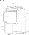
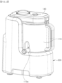
- FIGS. 1 and 2 are perspective views illustrating a vacuum blender according to the present disclosure
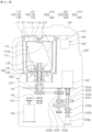
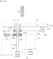
- FIG. 3 is a view illustrating an inner portion of a vacuum blender according to an exemplary embodiment in the present disclosure
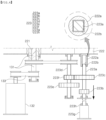
- FIGS. 4 and 5 are views illustrating an operation state of an inner container driving unit in the vacuum blender of FIG. 3 .
- a vacuum blender according to an exemplary embodiment in the present disclosure includes a blender body and an inner container unit.
- the blender body 100 includes an outer container 110, a grinding blade 120, and a blade driving unit 130.
- the outer container 110 has an upper opened structure in which a lower surface thereof is closed and an upper portion thereof is opened so that an object to be blended may be accommodated therein, and is covered by a blender cover 140 pivotable mounted on a container support case 300 to be described later.
- the outer container 110 is opened and closed by an outer container cover 111, and may be closed by the outer container cover 111 covering an upper portion thereof before being seated on the container support case 300.
- the object to be blended refers to food ground by an operation of a vacuum blender.
- the grinding blade 120 is disposed in an inner container 210, and serves to grind and liquefy the object to be blended in the inner container 210 when being rotated.
- the blade driving unit 130 is configured to rotate the grinding blade 120.
- the outer container 110 is a structure seated on the container support case 300. That is, the outer container 110 is supported by the container support case 300, and such a container support case 300 has an L-shape as a whole as illustrated in the drawings.
- the container support case 300 includes a lower casing part 310 positioned below the outer container 110 and a side casing part 320 extending upward from the lower casing part 310 and connected to the blender cover 140.
- the outer container 110 is seated on an upper surface of the lower casing part 310 disposed in a transverse direction, and the blender cover 140 is hinge-coupled to an upper end of the side casing part 320 extending upward from the lower casing part 310 and disposed in a longitudinal direction so as to be pivotable in an up and down direction.
- Such a container support case 300 has the blade driving unit 130 and an inner container driving unit 220 to be described later installed therein.
- the grinding blade 120 positioned in the inner container 210 and the blade driving unit 130 installed in the container support case 300 are connected to each other so that a driving force is transferred
- the inner container 210 installed in the outer container 110 and the inner container driving unit 220 installed in the container support case 300 are connected to each other so that a driving force is transferred.
- the outer container 110 is detachably connected to the container support case 300.
- a spiral projection to be fitted into the container support case 300 is formed on an outer peripheral surface of a lower protrusion part of the outer container 110, a spiral groove is formed in an inner peripheral surface of a seating groove of container support case 300 on which the lower protrusion part is seated, and the projection is fitted into the spiral groove, such that the outer container may be mounted on the container support case 300, and the projection is released from the spiral groove, such that the outer case may be separated from the container support case 300.
- an inner container unit 200 includes the inner container 210 and the inner container driving unit 220.
- the inner container 210 is installed in the outer container 110, is opened and closed by an inner container cover 211, and may be closed by the inner container cover 211 covering an upper portion thereof before being seated on the container support case 300.
- the inner container cover 211 may be rotatably assembled to the outer container cover 111.
- a central projection 211a may be formed at an upper portion of the inner container cover 211, and a projection support groove 111a into which the central projection 211a of the inner container cover 211 is inserted and rotationally supported may be formed at a lower portion of the outer container cover 111.
- a suction hole may be formed in the central projection 211a, and a suction hole may be formed in an upper portion of the projection support groove 111a.
- such an inner container 210 may have one or more protrusion parts 213 formed on inner side surfaces thereof so that the object to be blended rotationally flowing while being ground by the grinding blade 120 is caught.
- the blade driving unit 130 and the inner container driving unit 220 are configured to rotate the grinding blade 120 and the inner container 210 in opposite directions, and when the grinding blade 120 is rotated in a state in which the object to be blended is accommodated in the inner container 210, if the object to be blended collides with the protrusion parts 213 formed on the inner side surfaces of the inner container 210 rotating in an opposite direction, large turbulence of the object to be blended is generated to increase a grinding effect of the object to be blended.
- the obj ect to be blended flows upward while being radially pushed out by a centrifugal force by the rotation of the grinding blade 120, and the protrusion parts 213 inducing a downward spiral flow of the object to be blended and having a screw protrusion part shape are formed on the inner side surfaces of the inner container 210 to allow the object to be blended to flow toward the grinding blade 120 disposed on the lower side of the inner container 210, such that the grinding effect of the vacuum blender may be further increased.
- a controller may control an inner container driving motor 222 of the inner container driving unit 220 to be described later to reversely rotate the inner container 210 in an opposite direction to the grinding blade 120 to perform repeated operations of reversely rotating and stopping the inner container 210.
- the inner container 210 may have a plurality of dehydration holes 210a formed in side portions thereof so that the object to be blended is dehydrated when being rotated in order to extract only juice from the object to be blended ground by the grinding blade 120.
- the dehydration holes 210a are illustrated to be large in the drawings, but the dehydration holes 210a are actually very small holes through which only the juice of the object to be blended may pass, and a plurality of holes may be formed as a mesh structure in the side portions of the inner container 210. Furthermore, the dehydration holes 210a may be directly formed in the side portions of the inner container 210 as illustrated in the drawings, and as another example, although not illustrated in the drawings, a structure in which mesh members formed as a separate member are mounted to be portions of the side portions of the inner container 210 may be used.
- the dehydration holes 210a may be formed in a lower portion or the side portions of the inner container 210. In this case, it is preferable that the dehydration holes 210a are not formed in the lower portion of the inner container 210, and are formed in the side portions of the inner container 210, and it is more preferable that the dehydration holes 210a are formed from a predetermined height or more of the side portions of the inner container 210, which is to maintain a state in which a predetermined amount of liquid is accommodated because a blending effect is increased when there is a predetermined amount of liquid (e.g., separate water or juice generated when blending the obj ect to be blended) when blending the object to be blended.
- a predetermined amount of liquid e.g., separate water or juice generated when blending the obj ect to be blended
- the dehydration holes 210a are formed from a predetermined height or more of the side portions of the inner container 210, since the inner container 210 rotates at a much faster speed when the object to be blended is dehydrated than when the object to be blended is ground, the juice easily moves upward along the inner side surfaces of the inner container 210, such that the juice may sufficiently come out of the inner container 210 through the dehydration holes 210a.
- a discharge pipe 110a protruding outward may be formed at a lower portion of the outer container 110 so that the juice dehydrated from the object to be blended is discharged outwardlly of the outer container 110.
- reference numerals in a description to be described later related to the discharge pipe 110a refer to FIGS. 3 to 5 .
- the discharge pipe 110a that is downward inclined may be formed at a lower end portion of a side portion of the outer container 110 so that the juice may be extracted without separating the outer container 110 from the container support case 300.
- a guide protrusion jaw 110c may be formed on one side of a lead portion of the discharge pipe 110a at a lower portion inside the outer container 110.
- the inner container 210 rotates at a high speed.
- the juice coming out of the inner container 210 through the dehydration holes 210a is affected by the high-speed rotation of the inner container 210 to continuously rotationally flow between the inner container 210 and the outer container 110, and thus, does not come out of the outer container well through the discharge pipe 110a.
- the rotational flow of the juice is continuously maintained between the inner container 210 and the outer container 110 by the high-speed rotation of the inner container 210, such that the juice is not easily introduced into the lead portion of the discharge pipe 110a.
- the guide protrusion jaw 110c is formed to protrude on one side of the lead portion of the discharge pipe at a lower portion of an inner surface of the outer container 110, and serves to block the rotational flow of the juice generated from the object to be blended to guide the juice so that the juice is introduced into the lead portion of the discharge pipe 110a.
- the inner container driving unit 220 is configured to rotate the inner container 210.
- the inner container driving unit 220 includes an inner container rotation shaft 221, an inner container driving motor 222, and an inner container driving connection part 223.
- the above-described blade driving unit 130 includes a blade rotation shaft 131, a blade driving motor 132, and a blade driving connection part 133.
- the inner container rotation shaft 221 is connected to the lower portion of the inner container 210 embedded in the outer container 110 so that a rotational driving force is transferred to the lower portion of the inner container 210 when the outer container 110 is seated on the container support case 300
- the blade rotation shaft 131 is connected to the lower portion of the grinding blade 120 embedded in the inner container 210 so that a rotational driving force is transferred to the lower portion of the grinding blade 120 when the outer container 110 is seated on the container support case 300.
- the blade rotation shaft 131 is installed to be axially rotated in a hollow formed in the inner container rotation shaft 221, and the blade rotation shaft 131 and the inner container rotation shaft 221 have a structure in which they are axially rotated independently of each other.
- the hollow of the inner container rotation shaft 221 is provided with a bearing so that the blade rotation shaft 131 may be installed in the hollow while penetrating through the hollow, such that the blade rotation shaft 131 may rotate independently of the inner container rotation shaft 221 inside the inner container rotation shaft 221.
- an intermediate rotation shaft unit 190 connecting the blade driving unit 130 and the grinding blade 120 to each other and connecting the inner container driving unit 220 and the inner container 210 to each other is installed in the outer container 110.
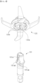
- the intermediate rotation shaft unit 190 may include a first intermediate rotation shaft 191 and a second intermediate rotation shaft 192.
- the first intermediate rotation shaft 191 has a structure in which it connects the blade rotation shaft 131 of the blade driving unit 130 and the grinding blade 120 to engage with each other.
- the second intermediate rotation shaft 192 has a structure in which it connects the inner container rotation shaft 221 of the inner container driving unit 220 and the inner container 210 to engage with each other.
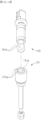
- the second intermediate rotation shaft 192 and the first intermediate rotation shaft 191 axially rotate independently of each other while the second intermediate rotation shaft 192 surrounds the first intermediate rotation shaft 191. That is, the first intermediate rotation shaft 191 is disposed in a hollow of the second intermediate rotation shaft 192, and a bearing is mounted between the first intermediate rotation shaft 191 and the second intermediate rotation shaft 192, such that the first intermediate rotation shaft 191 and the second intermediate rotation shaft 192 have a structure in which they are axially rotated independently of each other while stably and firmly maintaining a spaced distance therebetween.
- first intermediate rotation shaft 191 has an upper portion key-fastened to the grinding blade 120 and a lower portion key-fastened to the blade rotation shaft 131
- second intermediate rotation shaft 192 has an upper portion key-fastened to the inner container 210 and a lower portion key-fastened to the inner container rotation shaft 221.
- the upper portion of the first intermediate rotation shaft 191 is inserted into and assembled to a lower groove 120a of the grinding blade 120, and is key-fastened to an inner side surface of the lower groove 120a, such that the grinding blade 120 has a structure in which it rotates in conjunction with the first intermediate rotation shaft 191 while being in a firm position fixed state in which it does not move in a lateral direction.
- the first intermediate rotation shaft 191 has first keyways 191a formed in side surfaces of an upper portion thereof, the grinding blade 120 has lower keys 120k formed to protrude on inner side surfaces of the lower groove 120a, and when the lower keys 120k are inserted into the first keyways 191a, the first intermediate rotation shaft 191 and the grinding blade 120 are key-fastened to each other.
- the grinding blade 120 tends to float upward when it is stopped after being rotated within the inner container 210.
- the first keyway 191a may have a structure in which it extends downward from an upper end of a side surface of the first intermediate rotation shaft 191 and extends in both side directions at a lower portion thereof, that is, a ⁇ -shape.
- the lower keys 120k of the grinding blade 120 are vertically inserted downward into the first keyways 191a, the lower keys 120k are horizontally moved to one side portions 191a at lower portions of the first keyways 191a when the first intermediate rotation shaft 191 rotates, and are horizontally moved to the other side portions 191ab at the lower portions of the first keyways 191a when the rotation of the first intermediate rotation shaft 191 is stopped.
- the grinding blade 120 and the first intermediate rotation shaft 191 are maintained in a state in which they are stably assembled (fastened) to each other.
- the grinding blade 120 may be separated in the upward direction at an intermediate point of a process in which the lower keys 120k are horizontally moved to the other side portion 191ab in a state in which the lower keys 120k are horizontally moved to one side portions 191aa at the lower portions of the first keyways 191a.
- the first intermediate rotation shaft 191 and the grinding blade 120 may be provided with magnetic materials attracting the first intermediate rotation shaft 191 and the grinding blade 120, respectively, in addition to the assembly structure of the grinding blade 120 to the first intermediate rotation shaft 191 described above.
- a shaft magnet SM is embedded in an upper portion of the first intermediate rotation shaft 191
- a body magnet BM is embedded in the grinding blade 120, such that the first intermediate rotation shaft 191 and the grinding blade 120 may have a structure in which they are attached to each other by magnetic forces of the shaft magnet SM and the body magnet BM together with the above-described key fastening.
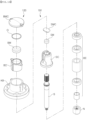
- the first intermediate rotation shaft 191 may include a lower nut N, a bearing part BE, a shaft member S, a shaft cap SC, the shaft magnet SM, and a shaft magnet cap SMC assembled from the lower side
- the grinding blade 120 may include a blade body KB, a body cover BC, the body magnet BM, an O-ring O, and a body magnet cap BMC in portions other than a blade.
- the lower portion of the first intermediate rotation shaft 191 is inserted into and assembled to an upper groove 131a of the blade rotation shaft 131, and is key-fastened to inner side surfaces of the upper groove 131a, such that the first intermediate rotation shaft 191 is in a firm position fixed state in which it does not move in the lateral direction, and has a structure in which it rotates in conjunction with the blade rotation shaft 131.
- the first intermediate rotation shaft 191 has first keys 191b formed on side surfaces of the lower portion thereof, the blade rotation shaft 131 has upper keyways 131g formed in an upper portion thereof, and when the first keys 191b are inserted into the upper keyways 131g, the first intermediate rotation shaft 191 and the blade rotation shaft 131 are key-fastened to each other.
- a lower hole 210b through which the first intermediate rotation shaft 191 penetrates is formed in the inner container 210, and a support jaw 210c is formed on an upper edge of the lower hole 210b.
- an upper portion of the second intermediate rotation shaft 192 is inserted into the lower hole 210b of the inner container 210 to be assembled while supporting the support jaw 210c of the inner container 210 upward, and is key-fastened to inner side surfaces of the lower hole 210b, such that the inner container 210 is in a firm position fixed state in which it does not move in the lateral direction, and has a structure in which it rotates in conjunction with the second intermediate rotation shaft 192.
- the second intermediate rotation shaft 192 has second keyways 192a formed in side surfaces of an upper portion thereof, the inner container 210 has lower keys 210k formed at the lower portion thereof, and when the lower keys 210k are inserted into the second keyways 192a, the second intermediate rotation shaft 192 and the inner container 210 are key-fastened to each other.
- a lower portion of the second intermediate rotation shaft 192 is key-fastened and assembled to the inner container rotation shaft 221, such that the second intermediate rotation shaft 192 is in a firm position fixed state in which it does not move in the lateral direction, has a structure in which it rotates in conjunction with the inner container rotation shaft 221.
- the second intermediate rotation shaft 192 has second keys 192b formed on side surfaces of the lower portion thereof, the inner container rotation shaft 221 has upper keyways 221g formed in an upper portion thereof, and when the second keys 192b are inserted into the upper keyways 221g, the second intermediate rotation shaft 192 and the inner container rotation shaft 221 are key-fastened to each other.
- the second keys 192b may have a structure in which they are inclined upward toward a rotation direction (counterclockwise direction in the drawing) of the inner container 210 so that they are smoothly guided and led into the upper keyways 221g when being inserted into the upper keyways 221g, and are firmly caught by the upper keyways 221g when being rotated in the rotation direction of the inner container 210, that is, an opposite direction of a rotation direction of the grinding blade 120.
- the blade rotation shaft 131 and the inner container rotation shaft 221 axially rotate independently of each other
- the intermediate rotation shaft unit 190 connecting the blade driving unit 130 and the grinding blade 120 to each other and connecting the inner container driving unit 220 and the inner container 210 to each other is installed in the outer container 110, such that the inner container 210 and the grinding blade 120 may rotate in opposite directions in a stable and balanced manner
- the outer container 110 is attached to and detached from the container support case 300, such that driving connection and driving disconnection between the grinding blade 120 and the blade driving unit 130 and between the inner container 210 and the inner container driving unit 220 may be smoothly and easily performed.
- the inner container driving unit 220 has a structure in which a gear fastening structure of the inner container driving connection part 223 is variable so that the inner container 210 has different rotation speeds when the obj ect to be blended is ground and dehydrated.
- the inner container driving connection part 223 has a gear fastening structure in which the inner container 210 has a slower rotation speed when the obj ect to be blended is ground than when the obj ect to be blended is dehydrated, and has a gear fastening structure in which the inner container 210 has a faster rotation speed when the object to be blended is dehydrated than when the object to be blended is ground.
- the vacuum blender according to the present disclosure may smoothly reversely rotate objects to be blended close to the inner side surfaces of the inner container 210 among objects to be blended rotating forward by a forward rotation of the grinding blade by decreasing a rotation speed of reverse rotation of the inner container 210 and increasing a torque when grinding the object to be blended, and may maximize a dehydration effect by increasing a rotation speed of the inner container 210 as much as possible when dehydrating the ground object to be blended as compared with when grinding the object to be blended.
- a driving small gear 223b and a driving large gear 223c are installed on an inner container driving shaft 223a connected to the inner container driving motor 222, and a driven large gear 223e and a driven small gear 223f are installed on the inner container rotation shaft 221 or an intermediate rotation shaft 223d rotating in conjunction with the inner container rotation shaft 221.
- the inner container driving shaft 223a and the inner container rotation shaft 221 may be disposed in parallel with each other, and as an example, the intermediate rotation shaft 223d may be disposed in parallel with the inner container driving shaft 223a and the inner container rotation shaft 221 as an additional driving force transfer medium when transferring a driving force from the inner container driving shaft 223a to the inner container rotation shaft 221.
- the driven large gear 223e and the driven small gear 223f may be installed directly on the inner container rotation shaft 221 or may be installed on the intermediate rotation shaft 223d as illustrated in the drawings, and a case where the driven large gear 223e and the driven small gear 223f are installed on the intermediate rotation shaft 223d will be described by way of example in the present specification.
- an arrangement of the driven large gear 223e and the driven small gear 223f to be described later may be applied to the inner container rotation shaft 221 when the driven large gear 223e and the driven small gear 223f are directly installed on the inner container rotation shaft 221.
- the driving small gear 223b and the driving large gear 223c are disposed on the inner container driving shaft 223a so as to be spaced apart from each other along an axial direction, and the driven large gear 223e and the driven small gear 223f are disposed on the intermediate rotation shaft 223d so as to be spaced apart from each other long the axial direction.
- the driving small gear 223b and the driving large gear 223c are sequentially disposed on the inner container driving shaft 223a and the driven large gear 223e and the driven small gear 223f are sequentially disposed on intermediate rotation shaft 223d so that the driving small gear 223b of the inner container driving shaft 223a corresponds to the driven large gear 223e of the intermediate rotation shaft 223d and the driving large gear 223c of the inner container driving shaft 223a corresponds to the driven small gear 223f of the intermediate rotation shaft 223d.
- the driving small gear 223b and the driving large gear 223c are sequentially disposed in the upward direction on the inner container driving shaft 223a
- the driven large gear 223e and the driven small gear 223f are sequentially disposed in the upward direction on the intermediate rotation shaft 223d.
- the driving small gear 223b has a relatively smaller diameter than the driving large gear 223c
- the driven large gear 223e has a relatively larger diameter than the driven small gear 223f.
- the inner container driving connection part 223 configured as described above may have a structure in which the driving large gear 223c and the driven small gear 223f are not gear-fastened to each other when the driving small gear 223b and the driven large gear 223e are gear-fastened to each other and the driving small gear 223b and the driven large gear 223e are not gear-fastened to each other when the driving large gear 223c and the driven small gear 223f are gear-fastened to each other, while the inner container driving shaft 223a reciprocates in the axial direction.
- the inner container driving shaft 223a moves downward in the axial direction, and thus, the driving large gear 223c and the driven small gear 223f are gear-fastened to each other, such that the inner container 210 is decelerated, but rotates with a large torque, and may thus rotate smoothly in an opposite direction to the grinding blade.
- the inner container driving shaft 223a moves upward in the axial direction, and thus, the driving small gear 223b and the driven large gear 223e are gear-fastened to each other, such that the inner container 210 rotates at a relatively faster speed than when the object to be blended is ground, and thus, a dehydration action of extracting the juice from the object to be blended may be effectively performed.
- the inner container driving connection part 223 may also have a structure in which the driving large gear 223c and the driven small gear 223f are not gear-fastened to each other when the driving small gear 223b and the driven large gear 223e are gear-fastened to each other and the driving small gear 223b and the driven large gear 223e are not gear-fastened to each other when the driving large gear 223c and the driven small gear 223f are gear-fastened to each other, while the intermediate rotation shaft 223d reciprocates in the axial direction, rather than the reciprocation of the inner container driving shaft 223a in the axial direction.
- the inner container driving connection part 223 may include a shaft moving member 223g moving the inner container driving shaft 223a in the axial direction.
- any driving member according to the related art such as a solenoid cylinder may be used as the shaft moving member 223g.
- the inner container driving shaft 223a may have one end portion axially movably slidably fastened to while being key-fastened to a motor shaft 222a of the inner container driving motor 222 so as to axially rotate in conjunction with the motor shaft 222a, and the other end portion axially rotatably connected to the shaft moving member 223g.
- the inner container driving shaft 223a has one end portion key-fastened to the motor shaft 222a of the inner container driving motor 222 so as to axially rotate in conjunction with the motor shaft 222a, such that when the motor shaft 222a axially rotates by an operation of the inner container driving motor 222, the inner container driving shaft 223a axially rotates in conjunction with the motor shaft 222a, and thus, receives a rotational driving force transferred from the inner container driving motor 222.
- the inner container driving shaft 223a has one end portion axially movably slidably fastened to the motor shaft 222a of the inner container driving motor 222, such that even when the inner container driving shaft 223a moves in the axial direction by the shaft moving member 223g, the inner container driving shaft 223a may be maintained in a state in which it is key-fastened to the motor shaft 222a.
- a cross section of a hollow 222b of the motor shaft 222a has a square shape
- a cross section of one end portion of the inner container driving shaft 223a is matched to the cross section of a hollow 222b of the motor shaft 222a in terms of shape, such that one end portion of the inner container driving shaft 223a may be axially movably slidably fastened to the motor shaft 222a while being key-fastened to the motor shaft 222a so as to axially rotate in conjunction with the motor shaft 222a.
- the other end portion of the inner container driving shaft 223a is connected to the shaft moving member 223g, such that the inner container driving shaft 223a may axially rotate in a state in which it is connected to the shaft moving member 223g when it moves in the axial direction by the shaft moving member 223g.
- the other end portion of the inner container driving shaft 223a maybe connected to the shaft moving member 223g by a shaft rotation bearing 223h.
- the inner container driving connection part 223 has a gear structure configured so that a rotation speed of the inner container 210 when the object to be blended is dehydrated is 5 times or more faster than a rotation speed of the inner container 210 when the object to be blended is ground.
- the inner container driving connection part 223 has a gear structure configured so that a rotation speed of the inner container 210 when the inner container 210 grinds the object to be blended is 50 rpm to 350 rpm and a rotation speed of the inner container 210 when the inner container 210 dehydrates the object to be blended is 1500 rpm to 3500 rpm.
- the vacuum blender according to the present disclosure may increase a torque as much as possible by decreasing the rotation speed of the inner container 210 when grinding the object to be blended, and maximize a dehydration effect by increasing the rotation speed of the inner container 210 as much as possible when dehydrating the object to be blended.
- FIG. 6 is a view illustrating an inner portion of a vacuum blender according to another exemplary embodiment in the present disclosure
- FIGS. 7 and 8 are views illustrating an operation state of an inner container driving unit in the vacuum blender of FIG. 6 .
- the blender body according to another exemplary embodiment in the present disclosure includes a blender body 100, an inner container unit 200, and a vacuum unit 400, and components other than an inner container driving unit 220 of the inner container unit 200 have the same structures as those of the vacuum blender illustrated in FIGS. 4 to 6 , and a detailed description thereof will thus be omitted.
- a structure in which the blade rotation shaft 131 of the blade driving unit 130 is axially rotatably installed in a hollow formed in the inner container rotation shaft 221 of the inner container driving unit 220, such that the blade rotation shaft 131 and the inner container rotation shaft 221 axially rotate independently of each other is also the same as the structure described above.
- the inner container driving unit 220 includes the inner container rotation shaft 221, an inner container driving motor 228, and an inner container driving connection part 229 connecting the inner container rotation shaft 221 and the inner container driving motor 228 to each other.
- a plurality of inner container driving motors 228 are provided so that the inner container 210 has different rotation speeds when grinding the object to be blended and when dehydrating the object to be blended.
- the vacuum blender according to the present disclosure may smoothly reversely rotate objects to be blended close to the inner side surfaces of the inner container 210 among objects to be blended rotating forward by a forward rotation of the grinding blade by decreasing a rotation speed of the inner container 210 using one inner container driving motors 228 to increase a torque when grinding the obj ect to be blended, and may maximize a dehydration effect by increasing a rotation speed of the inner container 210 as much as possible using another inner container driving motors 228 when dehydrating the ground object to be blended as compared with when grinding the object to be blended.
- one inner container driving motor 228 is a first motor M1 supplying a rotational driving force to the inner container 210 when grinding the object to be blended
- another inner container driving motor 228 is a second motor M2 supplying a rotational driving force to the inner container 210 in an opposite direction to the first motor M1 when dehydrating the ground object to be blended.
- the inner container driving connection part 229 has a structure in which each of the first motor M1 and the second motor M2 and the inner container rotation shaft 221 are connected to each other by a one-way bearing structure.
- first motor M1 and the inner container rotation shaft 221 may be connected to each other by one one-way bearing structure, and the second motor M2 and the inner container rotation shaft 221 may be connected to each other by another one-way bearing structure.
- the inner container rotation shaft 221 is rotationally driven only by the first motor M1 as illustrated in FIG. 7
- the inner container rotation shaft 221 is rotationally driven only by the second motor M2, as illustrated in FIG. 8 .
- the inner container driving connection part 229 has the following structure.
- a first driving gear 229a is installed on a first motor shaft M1a of the first motor M1, and a first driven gear 229c gear-fastened to the first driving gear 229a or connected to the first driving gear 229a by a first belt 229b or a first chain is installed on the inner container rotation shaft 221.
- the inner container rotation shaft 221 is installed with the first driven gear 229c driving-connected to the first driving gear 229a, and such a first driven gear 229c may be directly gear-fastened to the first driving gear 229a or be connected to the first driving gear 229a by a driving connecting member such as the first belt 229b or the first chain.
- a separate intermediate connection shaft may be further installed in a driving connection structure between the first motor shaft M1a and the inner container rotation shaft 221, and a rotation speed and a torque of the inner container rotation shaft 221 may be adjusted through an intermediate connection gear mounted on such an intermediate connection shaft and driving-connected to the first driving gear 229a and the first driven gear 229c.
- a second driving gear 229e is installed on a second motor shaft M2a of the second motor M2, and a second driven gear 229g gear-fastened to the second driving gear 229e or connected to the second driving gear 229e by a second belt 229f or a second chain is installed on the inner container rotation shaft 221.
- the inner container rotation shaft 221 is installed with the second driven gear 229g driving-connected to the second driving gear 229e, and such a second driven gear 229g may be directly gear-fastened to the second driving gear 229e or be connected to the second driving gear 229e by a driving connecting member such as the second belt 229f or the second chain.
- an intermediate rotation shaft may be further installed as a separate driving transfer medium in a driving connection structure between the second motor shaft M2a and the inner container rotation shaft 221, and a rotation speed and a torque of the inner container rotation shaft 221 may be adjusted through an intermediate connection gear installed on such an intermediate rotation shaft and driving-connected to the second driving gear 229e and the second driven gear 229g.
- a first one-way bearing 229d is mounted between the inner container rotation shaft 221 and the first driven gear 229c.
- the inner container rotation shaft 221 penetrates through the first driven gear 229c, and the first one-way bearing 229d has an inner race fixedly fastened to a circumference of the inner container rotation shaft 221 between the inner container rotation shaft 221 and the first driven gear 229c and an outer race fixedly fastened to an inner portion of the first driven gear 229c.
- Such a first one-way bearing 229d serves to allow a driving force to be transferred from the first driven gear 229c to the inner container rotation shaft 221 in only one axial rotation direction, and simply axially rotatably fasten the first driven gear 229c and the inner container rotation shaft 221 to each other in an opposite direction so that a driving force is not transferred in the opposite direction.
- the first one-way bearing 229d allows the driving force to be transferred from the first driven gear 229c to the inner container rotation shaft 221 so that the inner container rotation shaft 221 also axially rotates in one direction in conjunction with the first driven gear 229c when the first driven gear 229c axially rotates in one direction, and allows the driving force not to be transferred from the inner container rotation shaft 221 to the first driven gear 229c so that the first driven gear 229c does not axially rotate in an opposite direction in conjunction with the inner container rotation shaft 221 when the inner container rotation shaft 221 rotates in the opposite direction.
- a second one-way bearing 229h is mounted between the inner container rotation shaft 221 and the second driven gear 229g.
- the inner container rotation shaft 221 penetrates through the second driven gear 229g, and the second one-way bearing 229h has an inner race fixedly fastened to the circumference of the inner container rotation shaft 221 between the inner container rotation shaft 221 and the second driven gear 229g and an outer race fixedly fastened to an inner portion of the second driven gear 229g.
- Such a second one-way bearing 229h serves to allow a driving force to be transferred from the second driven gear 229g to the inner container rotation shaft 221 in only one axial rotation direction, and simply axially rotatably fasten the second driven gear 229g and the inner container rotation shaft 221 to each other in an opposite direction so that a driving force is not transferred in the opposite direction.
- the second one-way bearing 229h allows the driving force to be transferred from the second driven gear 229g to the inner container rotation shaft 221 so that the inner container rotation shaft 221 also axially rotates in the other direction in conjunction with the second driven gear 229g when the second driven gear 229g axially rotates in the other direction, and allows the driving force not to be transferred from the inner container rotation shaft 221 to the second driven gear 229g so that the second driven gear 229g does not axially rotate in an opposite direction in conjunction with the inner container rotation shaft 221 when the inner container rotation shaft 221 rotates in the opposite direction.
- first one-way bearing 229d and the second one-way bearing 229h have structures in which the driving forces are transferred only in opposite rotation directions.
- the second driven gear 229g does not rotate, and ultimately, does not affect the second motor M2
- the second driven gear 229g rotates through the second driving gear 229e when only the second motor M2 operates
- the first driven gear 229c does not rotate, and ultimately, does not affect the first motor M1.
- the first motor M1, the second motor M2, and the inner container driving connection part 229 may be configured so that a rotation speed of the inner container 210 when the object to be blended is dehydrated is 5 times or more faster than a rotation speed of the inner container 210 when the object to be blended is ground.
- the firstmotorM1, the second motor M2, and the inner container driving connection part 229 are configured so that a rotation speed of the inner container 210 when the inner container 210 grinds the obj ect to be blended is 50 rpm to 350 rpm and a rotation speed of the inner container 210 when the inner container 210 dehydrates the object to be blended is 1500 rpm to 3500 rpm.
- the vacuum blender according to the present disclosure may increase a torque as much as possible by decreasing the rotation speed of the inner container 210 when grinding the object to be blended, and maximize a dehydration effect by increasing the rotation speed of the inner container 210 as much as possible when dehydrating the object to be blended.
- the vacuum blender according to the present disclosure may further include a vacuum unit 400 installed in the container support case 300 so as to form a vacuum in the inner container 210, as illustrated in FIGS. 3 and 6 .
- the vacuum unit 400 may include a suction pipe 410 and a vacuum driving unit 420.
- the suction pipe 410 may have a structure in which it extends from the vacuum driving unit 420 embedded in the container support case 300 upward of the outer container 110 through an inner portion of the blender cover 140, and communicates with the inner container 210 disposed in the outer container 110 while communicating with the outer container 110 when the blender cover 140 pivots downward to cover the outer container 110.
- the vacuum driving unit 420 may be connected to the suction pipe 410, and may be formed of a vacuum motor and a vacuum pump.
- the vacuum blender of the present disclosure allows a blending operation including the grinding and the dehydration for the obj ect to be blended accommodated in the inner container to be performed under the vacuum by the vacuum unit 400 configured as described above, such that the obj ect to be blended including a fruit or a vegetable is blended in a state in which it is not oxidized, and juice which is fresh and of which a nutritive substance is not destroyed may be obtained.
- the vacuum blender has a structure in which the gear fastening structure of the inner container driving connection part 223 varies or the plurality of inner container driving motors 228 are configured so that the inner container 210 has different rotation speeds when grinding the object to be blended and when dehydrating the object to be blended, and thus, the vacuum blender may smoothly reversely rotate the objects to be blended close to the inner side surfaces of the inner container 210 among the objects to be blended rotating forward by the forward rotation of the grinding blade by decreasing the rotation speed of the reverse rotation of the inner container 210 and increasing the torque when grinding the object to be blended, and may maximize the dehydration effect by increasing the rotation speed of the inner container 210 as much as possible when dehydrating the ground object to be blended as compared with when grinding the object to be blended. with when grinding the object to be blended.
Landscapes
- Engineering & Computer Science (AREA)
- Food Science & Technology (AREA)
- Mechanical Engineering (AREA)
- Food-Manufacturing Devices (AREA)
- Crushing And Pulverization Processes (AREA)
Claims (10)
- Vakuummixer, umfassend:einen Mixerkörper (100), enthaltend ein Behälterträgergehäuse (300), einen Außenbehälter (110), der auf dem Behälterträgergehäuse (300) angeordnet ist, eine Mahlklinge (120) und eine Klingenantriebseinheit (130), welche die Mahlklinge (120) dreht,eine Innenbehältereinheit (200), enthaltend einen Innenbehälter (210), der in dem Außenbehälter (110) angeordnet ist und in dem die Mahlklinge (120) positioniert ist, und einer Innenbehälterantriebseinheit (220), die den Innenbehälter (210) dreht, undeine Vakuumeinheit (400), die in dem Behälterträgergehäuse (300) installiert und dazu beschaffen ist, einen Mischvorgang für ein im Innenbehälter (210) untergebrachtes zu mischendes Objekt in einem Vakuumzustand auszuführen,wobei der Außenbehälter(110) durch eine Außenbehälterabdeckung (111) geöffnet und geschlossen wird, der Innenbehälter (210) durch eine Innenbehälterabdeckung (211) geöffnet und geschlossen wird und die Innenbehälterabdeckung (211) drehbar an der Außenbehälterabdeckung (111) angebracht ist undeine Klingendrehwelle (131) der Klingenantriebseinheit (130) so installiert ist, dass sie sich axial in einem Hohlraum dreht, der in einer Innenbehälterdrehwelle (221) der Innenbehälterantriebseinheit (220) ausgebildet ist, so dass die Klingendrehwelle (131) und die Innenbehälterdrehwelle (221) unabhängig voneinander axial gedreht werden,dadurch gekennzeichnet, dass eine Zwischendrehwelleneinheit (190), welche die Klingenantriebseinheit (130) und die Schleifklinge (120) miteinander verbindet und die Innenbehälterantriebseinheit (220) und den Innenbehälter (210) miteinander verbindet, im Außenbehälter (110) installiert ist.
- Vakuummixer nach Anspruch 1, wobei die Klingenantriebseinheit (130) und die Innenbehälterantriebseinheit (220) im Behälterträgergehäuse (300) montiert sind und der Außenbehälter (110) abnehmbar mit dem Behälterträgergehäuse (300) verbunden ist,
wobei die Zwischendrehwelleneinheit (190) umfasst:eine erste Zwischendrehwelle (191), welche die Klingendrehwelle (131) der Klingenantriebseinheit (130) und die Mahlklinge (120) verbindet, so dass sie miteinander in Eingriff kommen, undeine zweite Zwischendrehwelle (192), welche die Innenbehälterdrehwelle (221) der Innenbehälterantriebseinheit (220) und den Innenbehälter (210) verbindet, so dass sie miteinander in Eingriff kommen, undsich die zweite Zwischendrehwelle (192) und die erste Zwischendrehwelle (191) axial unabhängig voneinander drehen, während die zweite Zwischendrehwelle (192) die erste Zwischendrehwelle (191) umgibt. - Vakuummixer nach Anspruch 2, wobei die erste Zwischendrehwelle (191) einen oberen Abschnitt, der mit dem Mahlmesser (120) verkeilt ist, und einen unteren Abschnitt, der mit der Messerdrehwelle (131) verkeilt ist, aufweist und
die zweite Zwischendrehwelle (192) einen oberen Abschnitt, der mit dem Innenbehälter (210) verkeilt ist, und einen unteren Abschnitt, der mit der Innenbehälterdrehwelle (221) verkeilt ist, aufweist. - Vakuummixer nach Anspruch 3, wobei die erste Zwischendrehwelle (191) erste Keilnuten (191a) aufweist, die in einem oberen Abschnitt davon ausgebildet sind, und die Mahlklinge (120) untere Keile (120k) aufweist, die an den Innenseitenflächen einer unteren Nut (120a) hervorstehen, die in der Mahlklinge (120) ausgebildet ist und mit Keilen an den ersten Keilnuten (191a) verkeilt ist, und
die erste Keilnut (191a) von einem oberen Ende einer Seitenfläche der ersten Zwischendrehwelle (191) nach unten verläuft und sich in einem unteren Abschnitt davon in beide Seitenrichtungen erstreckt. - Vakuummixer nach Anspruch 3, wobei ein Wellenmagnet (SM) in einen oberen Abschnitt der ersten Zwischendrehwelle (191) eingebettet ist und ein Körpermagnet (BM) in die Mahlklinge (120) eingebettet ist, so dass die erste Zwischendrehwelle (191) und die Mahlklinge (120) durch magnetische Kräfte des Wellenmagneten (SM) und des Körpermagneten (BM) zusammen mit der Verkeilung aneinander angebracht sind.
- Vakuummixer nach Anspruch 3, wobei im Innenbehälter (210) ein unteres Loch (210b) ausgebildet ist, durch das die erste Zwischendrehwelle (191) verläuft, und eine Stützbacke an einer oberen Kante des unteren Lochs (210b) ausgebildet ist, und
ein oberer Abschnitt der zweiten Zwischendrehwelle (192) in das untere Loch (210b) des Innenbehälters (210) eingesetzt ist, so dass sie zusammengebaut sind, während die Stützbacke des Innenbehälters (210) nach oben gestützt wird, und mit den Innenseitenflächen des unteren Lochs (210b) verkeilt ist, und ein unterer Abschnitt der zweiten Zwischendrehwelle (192) in eine obere Nut (131a) der Innenbehälterdrehwelle (221) eingesetzt und daran montiert ist und mit den Innenseitenflächen der oberen Nut (131a) verkeilt ist. - Vakuummixer nach Anspruch 1, wobei die Klingenantriebseinheit (130) und die Innenbehälterantriebseinheit (220) dazu beschaffen sind, die Mahlklinge (120) und den Innenbehälter (210) in entgegengesetzte Richtungen zu drehen.
- Vakuummixer nach Anspruch 7, wobei der Innenbehälter (210) einen Vorsprungsteil (213) aufweist, der an einer Innenseite ausgebildet ist, so dass das zu mixende Objekt, das drehend fließt, während es von der Mahlklinge (120) gemahlen wird, aufgefangen wird und
der Vorsprungsteil (213) die Form einer schraubenförmigen Vorsprungslinie aufweist, die eine nach unten gerichtete Spiralströmung des zu mixenden Objekts bewirkt, so dass das zu mixende Objekt nach unten fließt, während es sich in eine entgegengesetzte Richtung zur Drehung der Mahlklinge (120) dreht. - Vakuummixer nach Anspruch 1, wobei der Innenbehälter (210) eine Vielzahl von Entwässerungslöchern (210a) aufweist, die in Seitenabschnitten davon ausgebildet sind, so dass das zu mixende Objekt beim Drehen entwässert wird.
- Vakuummixer nach Anspruch 9, wobei ein nach außen vorstehendes Auslassrohr (110a) an einem unteren Abschnitt des Außenbehälters (110) ausgebildet ist, so dass aus dem zu mixenden Objekt entwässerter Saft aus dem Außenbehälter (110) nach außen ausgetragen wird, und
eine Führungsvorsprungsbacke (110c) so ausgebildet ist, dass sie an einer Seite eines vorderen Abschnitts des Auslassrohrs (110a) an einem unteren Abschnitt einer Innenfläche des Außenbehälters (110) hervorsteht, so dass sie einen Drehfluss des aus dem zu mixenden Objekt erzeugten Safts blockiert, um zu ermöglichen, dass der Saft zum vorderen Abschnitt des Auslassrohrs (110a) geleitet und in diesen eingeführt wird.
Applications Claiming Priority (2)
| Application Number | Priority Date | Filing Date | Title |
|---|---|---|---|
| KR1020190130706A KR102195153B1 (ko) | 2019-10-21 | 2019-10-21 | 진공믹서기 |
| PCT/KR2020/013059 WO2021080204A1 (ko) | 2019-10-21 | 2020-09-25 | 진공믹서기 |
Publications (3)
| Publication Number | Publication Date |
|---|---|
| EP4049566A1 EP4049566A1 (de) | 2022-08-31 |
| EP4049566A4 EP4049566A4 (de) | 2022-12-14 |
| EP4049566B1 true EP4049566B1 (de) | 2024-10-30 |
Family
ID=74086843
Family Applications (1)
| Application Number | Title | Priority Date | Filing Date |
|---|---|---|---|
| EP20879905.6A Active EP4049566B1 (de) | 2019-10-21 | 2020-09-25 | Vakuummischer |
Country Status (7)
| Country | Link |
|---|---|
| US (1) | US12543894B2 (de) |
| EP (1) | EP4049566B1 (de) |
| JP (1) | JP7357154B2 (de) |
| KR (1) | KR102195153B1 (de) |
| CN (1) | CN114745995B (de) |
| PL (1) | PL4049566T3 (de) |
| WO (1) | WO2021080204A1 (de) |
Families Citing this family (5)
| Publication number | Priority date | Publication date | Assignee | Title |
|---|---|---|---|---|
| USD990965S1 (en) * | 2021-01-18 | 2023-07-04 | Lg Electronics Inc. | Blender |
| CN113425174B (zh) * | 2021-08-20 | 2025-07-04 | 珠海格力电器股份有限公司 | 一种食物加工器具 |
| CN115886605A (zh) * | 2021-09-30 | 2023-04-04 | 广东美的白色家电技术创新中心有限公司 | 料理机及其接头组件 |
| CN220917193U (zh) * | 2023-08-16 | 2024-05-10 | 上海爱餐机器人(集团)有限公司 | 安装炒锅装置中各功能部件的基座及带该基座的炒锅装置 |
| EP4512289A1 (de) * | 2023-08-25 | 2025-02-26 | Versuni Holding B.V. | Lebensmittelzubereitungsvorrichtung und lebensmittelzubereitungsanordnung damit |
Family Cites Families (21)
| Publication number | Priority date | Publication date | Assignee | Title |
|---|---|---|---|---|
| JP3187443B2 (ja) | 1991-02-21 | 2001-07-11 | 東邦石油株式会社 | 金属表面被膜の加熱剥離装置 |
| US5257575A (en) * | 1991-12-20 | 1993-11-02 | Trillium Health Products, Inc. | Juice extractors with splash prevention |
| JP2004016572A (ja) * | 2002-06-18 | 2004-01-22 | Yufoosu:Kk | 手動食品加工機 |
| KR20110138108A (ko) | 2010-06-18 | 2011-12-26 | 웅진코웨이주식회사 | 브러쉬를 포함하는 주서기 |
| CN103124510B (zh) * | 2010-09-27 | 2015-06-24 | 三洋电机株式会社 | 自动制面包机 |
| CN202051589U (zh) * | 2011-04-08 | 2011-11-30 | 九阳股份有限公司 | 一种挤压式食品加工机 |
| CN202365584U (zh) * | 2011-11-23 | 2012-08-08 | 江苏顺发电器有限公司 | 一种榨汁机 |
| KR101226441B1 (ko) * | 2012-08-13 | 2013-01-28 | 김화식 | 주스 착즙기 |
| KR101381662B1 (ko) * | 2012-08-30 | 2014-04-04 | 주식회사 하도 | 마그네틱 커플링을 이용한 믹서기 |
| KR101384985B1 (ko) * | 2012-09-28 | 2014-04-14 | 주식회사 대성아트론 | 탈 부착이 용이한 칼날 교체형 믹서기 |
| TW201336583A (zh) | 2013-03-05 | 2013-09-16 | Qiao-Fu Yang | 按壓式攪拌容器結構 |
| CN203138172U (zh) * | 2013-03-07 | 2013-08-21 | 张建荣 | 搅拌机 |
| KR20170079453A (ko) * | 2015-12-30 | 2017-07-10 | 코웨이 주식회사 | 누름식 진공 형성부를 포함하는 주서기 |
| KR102489264B1 (ko) * | 2016-02-16 | 2023-01-17 | 엘지전자 주식회사 | 믹서기 |
| KR101772862B1 (ko) | 2016-10-04 | 2017-09-01 | 주식회사 인트로팩 | 믹서기 |
| CN107136893A (zh) * | 2017-07-08 | 2017-09-08 | 佛山市正略信息科技有限公司 | 一种具有快速过滤功能的榨汁机 |
| US11026544B2 (en) * | 2017-07-24 | 2021-06-08 | Joung Geun Ahn | Vacuum blender |
| KR102008731B1 (ko) * | 2017-08-22 | 2019-08-09 | 주식회사 인트로팩 | 진공믹서기 |
| KR101974747B1 (ko) * | 2017-10-24 | 2019-05-02 | (주)제이월드텍 | 진공믹서기 |
| KR102059394B1 (ko) * | 2019-07-24 | 2019-12-26 | 주식회사 인트로팩 | 진공믹서기 |
| KR102836707B1 (ko) * | 2019-08-13 | 2025-07-18 | 엘지전자 주식회사 | 블렌더 |
-
2019
- 2019-10-21 KR KR1020190130706A patent/KR102195153B1/ko active Active
-
2020
- 2020-09-25 EP EP20879905.6A patent/EP4049566B1/de active Active
- 2020-09-25 WO PCT/KR2020/013059 patent/WO2021080204A1/ko not_active Ceased
- 2020-09-25 CN CN202080073602.3A patent/CN114745995B/zh active Active
- 2020-09-25 JP JP2022523358A patent/JP7357154B2/ja active Active
- 2020-09-25 US US17/769,836 patent/US12543894B2/en active Active
- 2020-09-25 PL PL20879905.6T patent/PL4049566T3/pl unknown
Also Published As
| Publication number | Publication date |
|---|---|
| WO2021080204A1 (ko) | 2021-04-29 |
| CN114745995B (zh) | 2024-03-29 |
| EP4049566A1 (de) | 2022-08-31 |
| US12543894B2 (en) | 2026-02-10 |
| EP4049566A4 (de) | 2022-12-14 |
| KR102195153B1 (ko) | 2020-12-28 |
| JP2022552738A (ja) | 2022-12-19 |
| US20220378250A1 (en) | 2022-12-01 |
| CN114745995A (zh) | 2022-07-12 |
| PL4049566T3 (pl) | 2025-03-17 |
| JP7357154B2 (ja) | 2023-10-05 |
Similar Documents
| Publication | Publication Date | Title |
|---|---|---|
| EP4049566A1 (de) | Vakuummischer | |
| EP3851001B1 (de) | Mischer | |
| KR101772862B1 (ko) | 믹서기 | |
| CN104812280B (zh) | 用于食物加工机的刀片驱动组件和包含其的食物加工机 | |
| EP3851002A1 (de) | Mischer | |
| US20120055351A1 (en) | Juice Extractor | |
| EP3566622A1 (de) | Entsaftungsschraube und entsafter dafür | |
| KR102059393B1 (ko) | 탈수가능한 믹서기 | |
| CN109965733A (zh) | 一种改进的具有料渣收集功能的食品处理机 | |
| JP5754994B2 (ja) | 攪拌装置 | |
| CN102670092A (zh) | 混合容器 | |
| KR102059394B1 (ko) | 진공믹서기 | |
| US20250031909A1 (en) | Vertically movable blender | |
| KR102081432B1 (ko) | 탈수가능한 믹서기 | |
| KR102094169B1 (ko) | 믹서기 | |
| KR102162080B1 (ko) | 순환식 믹서기 | |
| CN207544974U (zh) | 一种食物处理器 | |
| CN216522792U (zh) | 一种食品加工用原料干燥装置 | |
| CN201033444Y (zh) | 食物切片/丝机 | |
| KR102569500B1 (ko) | 믹서기 및 믹서기의 제어방법 | |
| CN208409988U (zh) | 一种药材切片器 | |
| CN220780585U (zh) | 一种营养膳食食品加工用研磨设备 | |
| KR200398242Y1 (ko) | 중탕용 과채 절단기 | |
| KR102248567B1 (ko) | 탈수가능한 믹서기 | |
| CN208541182U (zh) | 一种食物料理机及其机头 |
Legal Events
| Date | Code | Title | Description |
|---|---|---|---|
| STAA | Information on the status of an ep patent application or granted ep patent |
Free format text: STATUS: THE INTERNATIONAL PUBLICATION HAS BEEN MADE |
|
| PUAI | Public reference made under article 153(3) epc to a published international application that has entered the european phase |
Free format text: ORIGINAL CODE: 0009012 |
|
| STAA | Information on the status of an ep patent application or granted ep patent |
Free format text: STATUS: REQUEST FOR EXAMINATION WAS MADE |
|
| 17P | Request for examination filed |
Effective date: 20220504 |
|
| AK | Designated contracting states |
Kind code of ref document: A1 Designated state(s): AL AT BE BG CH CY CZ DE DK EE ES FI FR GB GR HR HU IE IS IT LI LT LU LV MC MK MT NL NO PL PT RO RS SE SI SK SM TR |
|
| A4 | Supplementary search report drawn up and despatched |
Effective date: 20221110 |
|
| RIC1 | Information provided on ipc code assigned before grant |
Ipc: A47J 43/07 20060101ALI20221104BHEP Ipc: A47J 43/08 20060101ALI20221104BHEP Ipc: A47J 44/00 20060101AFI20221104BHEP |
|
| DAV | Request for validation of the european patent (deleted) | ||
| DAX | Request for extension of the european patent (deleted) | ||
| GRAP | Despatch of communication of intention to grant a patent |
Free format text: ORIGINAL CODE: EPIDOSNIGR1 |
|
| STAA | Information on the status of an ep patent application or granted ep patent |
Free format text: STATUS: GRANT OF PATENT IS INTENDED |
|
| INTG | Intention to grant announced |
Effective date: 20240517 |
|
| RAP1 | Party data changed (applicant data changed or rights of an application transferred) |
Owner name: NUC ELECTRONICS CO., LTD. Owner name: INTROPACK CO., LTD. |
|
| GRAS | Grant fee paid |
Free format text: ORIGINAL CODE: EPIDOSNIGR3 |
|
| GRAA | (expected) grant |
Free format text: ORIGINAL CODE: 0009210 |
|
| STAA | Information on the status of an ep patent application or granted ep patent |
Free format text: STATUS: THE PATENT HAS BEEN GRANTED |
|
| AK | Designated contracting states |
Kind code of ref document: B1 Designated state(s): AL AT BE BG CH CY CZ DE DK EE ES FI FR GB GR HR HU IE IS IT LI LT LU LV MC MK MT NL NO PL PT RO RS SE SI SK SM TR |
|
| REG | Reference to a national code |
Ref country code: GB Ref legal event code: FG4D |
|
| REG | Reference to a national code |
Ref country code: CH Ref legal event code: EP |
|
| REG | Reference to a national code |
Ref country code: DE Ref legal event code: R096 Ref document number: 602020040554 Country of ref document: DE |
|
| REG | Reference to a national code |
Ref country code: IE Ref legal event code: FG4D |
|
| P01 | Opt-out of the competence of the unified patent court (upc) registered |
Free format text: CASE NUMBER: APP_66630/2024 Effective date: 20241217 |
|
| REG | Reference to a national code |
Ref country code: NL Ref legal event code: FP |
|
| REG | Reference to a national code |
Ref country code: LT Ref legal event code: MG9D |
|
| PG25 | Lapsed in a contracting state [announced via postgrant information from national office to epo] |
Ref country code: PT Free format text: LAPSE BECAUSE OF FAILURE TO SUBMIT A TRANSLATION OF THE DESCRIPTION OR TO PAY THE FEE WITHIN THE PRESCRIBED TIME-LIMIT Effective date: 20250228 Ref country code: HR Free format text: LAPSE BECAUSE OF FAILURE TO SUBMIT A TRANSLATION OF THE DESCRIPTION OR TO PAY THE FEE WITHIN THE PRESCRIBED TIME-LIMIT Effective date: 20241030 Ref country code: IS Free format text: LAPSE BECAUSE OF FAILURE TO SUBMIT A TRANSLATION OF THE DESCRIPTION OR TO PAY THE FEE WITHIN THE PRESCRIBED TIME-LIMIT Effective date: 20250228 |
|
| PG25 | Lapsed in a contracting state [announced via postgrant information from national office to epo] |
Ref country code: FI Free format text: LAPSE BECAUSE OF FAILURE TO SUBMIT A TRANSLATION OF THE DESCRIPTION OR TO PAY THE FEE WITHIN THE PRESCRIBED TIME-LIMIT Effective date: 20241030 |
|
| REG | Reference to a national code |
Ref country code: AT Ref legal event code: MK05 Ref document number: 1736056 Country of ref document: AT Kind code of ref document: T Effective date: 20241030 |
|
| PG25 | Lapsed in a contracting state [announced via postgrant information from national office to epo] |
Ref country code: BG Free format text: LAPSE BECAUSE OF FAILURE TO SUBMIT A TRANSLATION OF THE DESCRIPTION OR TO PAY THE FEE WITHIN THE PRESCRIBED TIME-LIMIT Effective date: 20241030 |
|
| PG25 | Lapsed in a contracting state [announced via postgrant information from national office to epo] |
Ref country code: ES Free format text: LAPSE BECAUSE OF FAILURE TO SUBMIT A TRANSLATION OF THE DESCRIPTION OR TO PAY THE FEE WITHIN THE PRESCRIBED TIME-LIMIT Effective date: 20241030 |
|
| PG25 | Lapsed in a contracting state [announced via postgrant information from national office to epo] |
Ref country code: NO Free format text: LAPSE BECAUSE OF FAILURE TO SUBMIT A TRANSLATION OF THE DESCRIPTION OR TO PAY THE FEE WITHIN THE PRESCRIBED TIME-LIMIT Effective date: 20250130 |
|
| PG25 | Lapsed in a contracting state [announced via postgrant information from national office to epo] |
Ref country code: GR Free format text: LAPSE BECAUSE OF FAILURE TO SUBMIT A TRANSLATION OF THE DESCRIPTION OR TO PAY THE FEE WITHIN THE PRESCRIBED TIME-LIMIT Effective date: 20250131 Ref country code: LV Free format text: LAPSE BECAUSE OF FAILURE TO SUBMIT A TRANSLATION OF THE DESCRIPTION OR TO PAY THE FEE WITHIN THE PRESCRIBED TIME-LIMIT Effective date: 20241030 Ref country code: AT Free format text: LAPSE BECAUSE OF FAILURE TO SUBMIT A TRANSLATION OF THE DESCRIPTION OR TO PAY THE FEE WITHIN THE PRESCRIBED TIME-LIMIT Effective date: 20241030 |
|
| PG25 | Lapsed in a contracting state [announced via postgrant information from national office to epo] |
Ref country code: RS Free format text: LAPSE BECAUSE OF FAILURE TO SUBMIT A TRANSLATION OF THE DESCRIPTION OR TO PAY THE FEE WITHIN THE PRESCRIBED TIME-LIMIT Effective date: 20250130 |
|
| PG25 | Lapsed in a contracting state [announced via postgrant information from national office to epo] |
Ref country code: SM Free format text: LAPSE BECAUSE OF FAILURE TO SUBMIT A TRANSLATION OF THE DESCRIPTION OR TO PAY THE FEE WITHIN THE PRESCRIBED TIME-LIMIT Effective date: 20241030 |
|
| PG25 | Lapsed in a contracting state [announced via postgrant information from national office to epo] |
Ref country code: DK Free format text: LAPSE BECAUSE OF FAILURE TO SUBMIT A TRANSLATION OF THE DESCRIPTION OR TO PAY THE FEE WITHIN THE PRESCRIBED TIME-LIMIT Effective date: 20241030 |
|
| PG25 | Lapsed in a contracting state [announced via postgrant information from national office to epo] |
Ref country code: EE Free format text: LAPSE BECAUSE OF FAILURE TO SUBMIT A TRANSLATION OF THE DESCRIPTION OR TO PAY THE FEE WITHIN THE PRESCRIBED TIME-LIMIT Effective date: 20241030 |
|
| PG25 | Lapsed in a contracting state [announced via postgrant information from national office to epo] |
Ref country code: RO Free format text: LAPSE BECAUSE OF FAILURE TO SUBMIT A TRANSLATION OF THE DESCRIPTION OR TO PAY THE FEE WITHIN THE PRESCRIBED TIME-LIMIT Effective date: 20241030 |
|
| PG25 | Lapsed in a contracting state [announced via postgrant information from national office to epo] |
Ref country code: SK Free format text: LAPSE BECAUSE OF FAILURE TO SUBMIT A TRANSLATION OF THE DESCRIPTION OR TO PAY THE FEE WITHIN THE PRESCRIBED TIME-LIMIT Effective date: 20241030 |
|
| PG25 | Lapsed in a contracting state [announced via postgrant information from national office to epo] |
Ref country code: CZ Free format text: LAPSE BECAUSE OF FAILURE TO SUBMIT A TRANSLATION OF THE DESCRIPTION OR TO PAY THE FEE WITHIN THE PRESCRIBED TIME-LIMIT Effective date: 20241030 |
|
| REG | Reference to a national code |
Ref country code: DE Ref legal event code: R097 Ref document number: 602020040554 Country of ref document: DE |
|
| PLBE | No opposition filed within time limit |
Free format text: ORIGINAL CODE: 0009261 |
|
| STAA | Information on the status of an ep patent application or granted ep patent |
Free format text: STATUS: NO OPPOSITION FILED WITHIN TIME LIMIT |
|
| PG25 | Lapsed in a contracting state [announced via postgrant information from national office to epo] |
Ref country code: SE Free format text: LAPSE BECAUSE OF FAILURE TO SUBMIT A TRANSLATION OF THE DESCRIPTION OR TO PAY THE FEE WITHIN THE PRESCRIBED TIME-LIMIT Effective date: 20241030 |
|
| 26N | No opposition filed |
Effective date: 20250731 |
|
| PGFP | Annual fee paid to national office [announced via postgrant information from national office to epo] |
Ref country code: DE Payment date: 20250926 Year of fee payment: 6 |
|
| PGFP | Annual fee paid to national office [announced via postgrant information from national office to epo] |
Ref country code: MC Payment date: 20250923 Year of fee payment: 6 |
|
| PGFP | Annual fee paid to national office [announced via postgrant information from national office to epo] |
Ref country code: IT Payment date: 20250922 Year of fee payment: 6 Ref country code: PL Payment date: 20250903 Year of fee payment: 6 Ref country code: NL Payment date: 20250925 Year of fee payment: 6 |
|
| PGFP | Annual fee paid to national office [announced via postgrant information from national office to epo] |
Ref country code: GB Payment date: 20250923 Year of fee payment: 6 |
|
| PGFP | Annual fee paid to national office [announced via postgrant information from national office to epo] |
Ref country code: FR Payment date: 20250925 Year of fee payment: 6 |
|
| REG | Reference to a national code |
Ref country code: CH Ref legal event code: H13 Free format text: ST27 STATUS EVENT CODE: U-0-0-H10-H13 (AS PROVIDED BY THE NATIONAL OFFICE) Effective date: 20260504 |