EP4049564B1 - Modulares handgeführtes küchengerät - Google Patents
Modulares handgeführtes küchengerät Download PDFInfo
- Publication number
- EP4049564B1 EP4049564B1 EP22153818.4A EP22153818A EP4049564B1 EP 4049564 B1 EP4049564 B1 EP 4049564B1 EP 22153818 A EP22153818 A EP 22153818A EP 4049564 B1 EP4049564 B1 EP 4049564B1
- Authority
- EP
- European Patent Office
- Prior art keywords
- gear
- grinder
- slip
- powerhead
- wheel
- Prior art date
- Legal status (The legal status is an assumption and is not a legal conclusion. Google has not performed a legal analysis and makes no representation as to the accuracy of the status listed.)
- Active
Links
Images












Classifications
-
- A—HUMAN NECESSITIES
- A47—FURNITURE; DOMESTIC ARTICLES OR APPLIANCES; COFFEE MILLS; SPICE MILLS; SUCTION CLEANERS IN GENERAL
- A47J—KITCHEN EQUIPMENT; COFFEE MILLS; SPICE MILLS; APPARATUS FOR MAKING BEVERAGES
- A47J43/00—Implements for preparing or holding food, not provided for in other groups of this subclass
- A47J43/04—Machines for domestic use not covered elsewhere, e.g. for grinding, mixing, stirring, kneading, emulsifying, whipping or beating foodstuffs, e.g. power-driven
- A47J43/07—Parts or details, e.g. mixing tools, whipping tools
- A47J43/0705—Parts or details, e.g. mixing tools, whipping tools for machines with tools driven from the upper side
- A47J43/0711—Parts or details, e.g. mixing tools, whipping tools for machines with tools driven from the upper side mixing, whipping or cutting tools
-
- A—HUMAN NECESSITIES
- A47—FURNITURE; DOMESTIC ARTICLES OR APPLIANCES; COFFEE MILLS; SPICE MILLS; SUCTION CLEANERS IN GENERAL
- A47J—KITCHEN EQUIPMENT; COFFEE MILLS; SPICE MILLS; APPARATUS FOR MAKING BEVERAGES
- A47J42/00—Coffee mills; Spice mills
- A47J42/38—Parts or details
- A47J42/46—Driving mechanisms; Coupling to drives
-
- A—HUMAN NECESSITIES
- A47—FURNITURE; DOMESTIC ARTICLES OR APPLIANCES; COFFEE MILLS; SPICE MILLS; SUCTION CLEANERS IN GENERAL
- A47J—KITCHEN EQUIPMENT; COFFEE MILLS; SPICE MILLS; APPARATUS FOR MAKING BEVERAGES
- A47J43/00—Implements for preparing or holding food, not provided for in other groups of this subclass
- A47J43/04—Machines for domestic use not covered elsewhere, e.g. for grinding, mixing, stirring, kneading, emulsifying, whipping or beating foodstuffs, e.g. power-driven
- A47J43/044—Machines for domestic use not covered elsewhere, e.g. for grinding, mixing, stirring, kneading, emulsifying, whipping or beating foodstuffs, e.g. power-driven with tools driven from the top side
-
- A—HUMAN NECESSITIES
- A47—FURNITURE; DOMESTIC ARTICLES OR APPLIANCES; COFFEE MILLS; SPICE MILLS; SUCTION CLEANERS IN GENERAL
- A47J—KITCHEN EQUIPMENT; COFFEE MILLS; SPICE MILLS; APPARATUS FOR MAKING BEVERAGES
- A47J43/00—Implements for preparing or holding food, not provided for in other groups of this subclass
- A47J43/04—Machines for domestic use not covered elsewhere, e.g. for grinding, mixing, stirring, kneading, emulsifying, whipping or beating foodstuffs, e.g. power-driven
- A47J43/06—Machines for domestic use not covered elsewhere, e.g. for grinding, mixing, stirring, kneading, emulsifying, whipping or beating foodstuffs, e.g. power-driven with a plurality of interchangeable working units, e.g. with a single driving-unit
-
- A—HUMAN NECESSITIES
- A47—FURNITURE; DOMESTIC ARTICLES OR APPLIANCES; COFFEE MILLS; SPICE MILLS; SUCTION CLEANERS IN GENERAL
- A47J—KITCHEN EQUIPMENT; COFFEE MILLS; SPICE MILLS; APPARATUS FOR MAKING BEVERAGES
- A47J43/00—Implements for preparing or holding food, not provided for in other groups of this subclass
- A47J43/04—Machines for domestic use not covered elsewhere, e.g. for grinding, mixing, stirring, kneading, emulsifying, whipping or beating foodstuffs, e.g. power-driven
- A47J43/07—Parts or details, e.g. mixing tools, whipping tools
- A47J43/08—Driving mechanisms
- A47J43/082—Driving mechanisms for machines with tools driven from the upper side
-
- B—PERFORMING OPERATIONS; TRANSPORTING
- B67—OPENING, CLOSING OR CLEANING BOTTLES, JARS OR SIMILAR CONTAINERS; LIQUID HANDLING
- B67B—APPLYING CLOSURE MEMBERS TO BOTTLES JARS, OR SIMILAR CONTAINERS; OPENING CLOSED CONTAINERS
- B67B7/00—Hand- or power-operated devices for opening closed containers
- B67B7/02—Hand- or power-operated devices for opening closed containers for removing stoppers
- B67B7/04—Cork-screws
- B67B7/0405—Power-operated cork-screws, e.g. operated by an electric motor
-
- A—HUMAN NECESSITIES
- A47—FURNITURE; DOMESTIC ARTICLES OR APPLIANCES; COFFEE MILLS; SPICE MILLS; SUCTION CLEANERS IN GENERAL
- A47J—KITCHEN EQUIPMENT; COFFEE MILLS; SPICE MILLS; APPARATUS FOR MAKING BEVERAGES
- A47J43/00—Implements for preparing or holding food, not provided for in other groups of this subclass
- A47J43/04—Machines for domestic use not covered elsewhere, e.g. for grinding, mixing, stirring, kneading, emulsifying, whipping or beating foodstuffs, e.g. power-driven
- A47J43/044—Machines for domestic use not covered elsewhere, e.g. for grinding, mixing, stirring, kneading, emulsifying, whipping or beating foodstuffs, e.g. power-driven with tools driven from the top side
- A47J2043/04409—Apparatus of hand held type
-
- A—HUMAN NECESSITIES
- A47—FURNITURE; DOMESTIC ARTICLES OR APPLIANCES; COFFEE MILLS; SPICE MILLS; SUCTION CLEANERS IN GENERAL
- A47J—KITCHEN EQUIPMENT; COFFEE MILLS; SPICE MILLS; APPARATUS FOR MAKING BEVERAGES
- A47J2201/00—Devices having a modular construction
Definitions
- This application is directed to a system of hand-held kitchen appliances having a single powerhead capable of being attached to a variety of kitchen appliances.
- attachments include, but are not limited to a blender, a whisker, a wine opener, a can opener, and a spice grinder.
- Modular hand-held kitchen appliances are known in the art. These products are typically built around an immersion blender as the main product. The products then include several simple attachments, such as a whisk or milk frother, to provide additional functions to the consumer. While these added attachments provide increased convenience to the consumer, the lack of other attachments and versatility prevent them from being a complete, modular, kitchen multitool.
- US 2018/0178367 discloses a modular kitchen appliance comprising a powerhead having a motor with a drive shaft, a grinder attachment removably attached to the powerhead, the grinder attachment having an attachment that is connected to the drive shaft of the motor.
- US 2016/0220068 discloses a spice mill which includes a gear mechanism operable in a first operational state wherein the gear mechanism is coupled to a first grinding mechanism and a second operational state wherein the gear mechanism is coupled to a second grinding mechanism.
- a selector connected to the gear mechanism is movable between a first position and a second position. The selector is transversely slidable and is connected to a pivoting rocker by means of a pair of fingers extending from the rocker, and the rocker is connected to each of two clutches.
- a cover part is rotatably mounted to the body and connected to the gear mechanism. Rotation of the cover part in a first direction rotates the first grinding mechanism when the gear mechanism is in the first operational state, and rotation of the cover part in the first direction rotates the second grinding mechanism when the gear mechanism is in the second operational state.
- a modular kitchen multitool of the present invention aims to provide a powered solution to a wide variety of kitchen tasks beyond what is currently available. These attachments go beyond simple mixing and blending and extend to other areas of the kitchen such as spice grinding.
- the present invention provides a modular kitchen appliance, comprising: a powerhead having a motor with a drive shaft; a grinder attachment removably attached to the powerhead, the grinder attachment having an attachment shaft that is connected to the drive shaft of the motor; the attachment shaft connected to a drive axle operatively connected to a first slip gear and a second slip gear; the first slip gear connected to a first grinder and the second slip gear connected to a second grinder; a hopper capable of holding two different materials for grinding; wherein in a first mode of operation, the first slip gear transfers power to the first grinder and the second slip gear does not transfer power to the second grinder, and in a second mode of operation the second slip gear transfers power to the second grinder and the first slip gear does not transfer power to the first grinder; wherein the first and second slip gears each have a top gear wheel and a bottom gear wheel that are selectively able to rotate relative to each other, wherein the top gear wheel and bottom gear wheel of each of the first and second slip gears have ramps that separate the top gear wheel from the bottom gear
- the motor may rotate in the same direction in both the first mode of operation and the second mode of operation.
- Fig. 1 shows the modular kitchen appliance system of the present invention.
- the system comprises a powerhead 10 that operates various kitchen appliance attachments that are selectively attached to the powerhead.
- various kitchen appliance attachments are shown, such as an immersion blender 12, whisk 14, milk frother 16, wine opener 18, spice grinder 20 and can opener 22. These examples are not exclusive.
- Figs 2 and 3 show the powerhead 10 in more detail.
- the powerhead comprises a housing 11 that enclose various components such as a motor 70 and a battery 72 (see Fig. 10 ).
- the housing 11 has a forward end 13, onto which the attachments are secured, and a rearward end 15.
- Fig. 2 shows a top portion of the powerhead 10 having a primary switch 24 for turning the powerhead on and off.
- a second safety switch 26 is adjacent the primary switch 24 and must be pressed simultaneously to power the motor.
- Fig. 3 shows a bottom of the powerhead 10 having a charging port 30 for charging the battery and a third reverse switch 28 that can reverse the rotational direction of the motor.
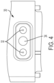
- Fig. 4 shows the charging port 30 having two charging pins or terminals 32 with a metal plate 34 therebetween.
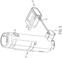
- a charger 36 (see Fig. 5 ) is connected to the charging port 30 and includes a charging head 37 that connects to the powerhead 10, and a wall plug 42 for connecting to a wall outlet.
- Figs. 5A and 5B show the charger head 37 with an overmold 39 surrounding a contact head 41.
- the overmold 39 is formed from two pieces 39A and 39B that enclose the contact head 41.
- the front overmold 39A is formed to correspond to the outer contour of the powerhead at the charging port 30 so a smooth fit is achieved.
- Fig. 5B shows the front overmold 39A removed to better show the contact head 41.
- Fig. 6 shows an end face of the charging head 37.
- the charging head has two spring contacts 38 and a magnet 40.
- the magnet 40 is attracted the metal plate 34 of the charging port 30 to secure the engagement between the charging pins 32 and the contacts 38.
- the charger 36 shown in Figs. 5 and 6 show a compact charger for users who have limited space and wish to hide the charger in a cabinet or drawer.
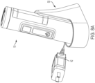
- Figs. 8 , 8A and 9 show an alternative cup style charger 50 for users with more space, allowing them to keep their powerhead 10 out in the open, for example on their countertop.
- the charger 50 is formed from two pieces, a base 60 (shown in Fig. 9 ) and a stantion 52 that's placed over the base.
- the stantion 52 provides an upright support for holding the powerhead 10 while charging and allows the user to easily insert and remove the powerhead 10 when needed.
- the stantion 52 includes an opening for securing and providing access to contact head 41, with a power cord 42 extending out from the stantion 52.
- a rear end of the powerhead 10 is shown having a rotatable cap 44.
- the cap 44 can be rotated between two positions which controls the speed of the motor 70. Rotating the cap 44 to the left in Fig. 7 slows the motor down, and rotating the cap 44 to the right increases the speed of the motor.
- the housing 11 holds the components of the powerhead, including the motor 70 and the battery pack 72.
- the motor 70 has a drive shaft 74 surrounded by an enclosure 76, which includes an opening 78 through which the drive shaft 74 can engage with the various attachments.
- a PCB 64 lies over the battery pack 72 and receives signals from the various switches and sensors on the powerhead to control the operation of the motor.
- the battery pack 72 provides energy to the motor 70 using rechargeable cells. However, it should be understood that removable (either disposable or rechargeable) batteries or even an AC power cord could power the motor and still fall within the scope of the invention.
- a switch 66 electrically connects the motor 70 and battery pack 72, and is actuated by switch 24.
- At least two Hall sensors 78 are provided adjacent enclosure 76.
- the Hall sensors 78 are used to identify the attachment connected to the powerhead 10 and adjust the powerheads operation accordingly. For example, a particular attachment may not need to reverse the motor or have multiple speed controls, and the Hall sensors would recognize the attachment and could disable those features.
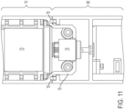
- Figs. 11-13 show various examples, and in particular Fig. 11 shows an attachment 80 with no magnets.
- the Hall sensors 78 detecting no magnet send a signal (or absence of a signal) to the PCB, which identifies the attachment and operates the powerhead in a first mode, whereby all the features of the powerhead are enabled. In other words, the powerhead motor can be reversed and/or its speed adjusted.
- Fig. 12 shows a second attachment 82 having a single magnet 84 that is positioned adjacent one of the Hall sensors 78.
- the Hall sensor 78 detects the magnet 84, and then instructs the powerhead to operate in a second mode, where the speed selector is disabled, but the motor reversing feature is enabled. This second mode is activated when only one magnet is sensed, regardless which Hall sensor is triggered.
- Fig. 13 shows a third attachment having two magnets 88 adjacent the two Hall sensor 78 when connected. Both Hall sensors 78 detect the presence of the magnets and instruct the powerhead to operate in a third mode where both the speed selector and reversing feature are disabled.
- the PCB 64 receives inputs from the switches 24, 26, 28 and the cap 44 to control the motor and other operational characteristics of the powerhead.
- Fig. 14 shows the powerhead 10 and a generic attachment 90.
- the attachment 90 can be any one of the attachments shown in Fig. 1 , but is shown generically here to illustrate how the attachment is secured to the powerhead 10.
- Fig. 15 shows the front end 13 of the powerhead 10.
- the enclosure 76 surrounding the motor drive shaft 74 includes a locking rail 92 and a tab 94.
- the attachment 90 has an interior space 96 into which the enclosure 76 is inserted.
- the attachment 90 includes a first rib 98 and a second rib 100 in a generally T-shaped configuration, projecting inwardly into the interior space 96.
- the attachment 90 is moved onto the powerhead 10 as shown by arrow 93 in Fig. 14 .
- the rib 98 is positioned adjacent a slot 102 formed by the rail 92, and then the attachment 90 is rotated.
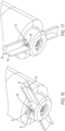
- the rib 98 then slides into the slot 102. See Figs. 16 and 17 which shows the movement of the ribs 98 and 100 as they are moved into the locked position.
- Fig. 15 shows the rail 92 is generally L-shaped, where a leg portion 104 is slightly angled to create a larger opening for the rib 98.
- the angled leg 104 allows for the rib 98 to more easily enter the slot 102 and also creates a cam surface that pulls the attachment 90 toward the powerhead 10, creating a tighter and firmer connection between the two.
- the tab 94 is flexible and includes a bump 106 on its free end that's flexed as the rib 100 slides over.
- the tab 94 provides haptic feedback notifying the user that the attachment has been properly secured.
- the tab 94 also functions to reduce the likelihood that the attachment 90 would inadvertently rotate out of the locked position.
- a second set of ribs 98 and 100 and corresponding rail 92 and tab 94 are positioned opposite the first set to provide a more secure connection between the powerhead 10 and attachment 90. Although two sets are shown in the figures, any number of ribs 98/100 and rail 92 tab 100 combinations could be used depending on how strong a connection is desired.
- FIG. 18 and 19 an alternative embodiment of the powerhead 110 is shown.
- the powerhead 110 is a simpler version of the powerhead 10, with some features removed to reduce cost and complexity.
- the powerhead 110 operates similarly to powerhead 10, including the how the attachments are connected to the powerhead as described above.
- identical elements to those found on powerhead 10 are given the same reference number here.
- the powerhead 110 includes a switch 24 for turning the device on and off.
- a reverse side includes a safety switch 26 which must be depressed simultaneously with the switch 24 for providing energy to the device.
- a charging port 30 provides electricity to the internal rechargeable battery pack 72.
- a rear cap 44 is rotatable in both the clockwise and counterclockwise directions to control the speed of the motor 70.
- the front end of the powerhead includes an enclosure 76 identical the previous embodiment, and the locking mechanism for the attachment can be identical as well.
- the powerhead 110 further include a pair of legs 112 prevent it from rolling around when lying on a flat surface.
- Fig. 20 shows the dual spice grinder attachment 20 secured to the powerhead 110 of the present invention.
- the dual spice grinder includes a hopper 204 for holding two different spices (or other material to be ground) in separate chambers.
- the spices can be any food material, including salt, peppercorn, coffee beans, seeds, etc.
- the spice grinder attachment 20 shown separately in Fig. 21 , includes a reduction gearbox housing 200, a spice selector 202 and the spice hopper 204.
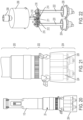
- Fig. 22 shows the internal gear assembly of the grinder attachment 20.
- Power is delivered to the grinder attachment 20 through an attachment shaft 208 that extends from the reduction gearbox housing 200 and is connected to the drive shaft 74 of the powerhead motor 70.
- the gearbox housing 200 includes a reduction gearbox 206 that reduces the rotational speed of the powerhead motor before it's transferred to grinders 224 and 226.
- the reduction gearbox 206 outputs to a drive axle 210 that is connected to a pair of slip gears 212 and 214.
- the drive axle 210 is fixedly connected to a drive gear 211 which engages slip gears 212 and 214, with the slip gears connected to respective grinder gears 216 and 218.
- the grinder gear 216 is attached to an axle 220 and grinder gear 218 is attached to axle 222.
- Each axle 220 and 222 is attached to grinder 224 and 226, which grind the spices in the hopper 204.
- the slip gear 212 includes a top gear wheel 212a and a bottom gear wheel 212b.
- the bottom gear wheel 212b is rotatably connected to grinder gear 216.
- the top gear wheel 212a includes a series of ramps 230a facing a corresponding series of ramps 230b on the bottom gear wheel 212b.
- the ramps having matching inclined surfaces 232a and 232b so that when the top gear wheel 212a is rotated in the counter-clockwise direction, the inclined surfaces 232a and 232b ride up one another and force the top gear wheel 212a upward until the ramps 230a and 230b disengage. At this point, the top gear wheel 212a slips and rotates relative to the bottom gear wheel 212b. When the top gear wheel 212a and bottom gear wheel 212b slip, the bottom gear wheel does not rotate, and no rotational movement is transferred to the grinder 224.
- the drive gear 211, slip gears 212 and 214, and grinder gears 216 and 218 are enclosed in the spice selector 202 by a top housing 240 and a bottom housing 242 and a spice selector wheel 244.
- the spice selector wheel 244 is rotatable with respect to the top housing 240 and bottom housing 242 to select which spice is to be ground.
- the spice selector wheel 244 has a protrusion 246 that projects from the bottom of the wheel, as shown in Fig. 25 .
- the wheel 244 rotates so that the protrusion 246 sits over one of the slip gears 212 or 214, thus preventing one of the top gear wheel (212a or 214a) from separating from its corresponding bottom gear wheel (212b or 214b).
- the protrusion 246 sits over the right slip gear 214, preventing the top gear wheel 214a from separating from its corresponding bottom gear wheel 214b. Without this separation, the top gear wheel 214a transfers its rotation to the bottom gear wheel 214b and ultimately to the grinder 226.
- the spice selector 202 determines which one of the grinders 224 or 226 is operational at any time.
- This design allows one of the two spices to be selected without having to change the rotational direction of the motor.
- switching between two different grinders was done by reversing the rotation of the motor, thereby engaging one set of gears and disengaging from a second set.
- the present design eliminates the need to a have a reversible motor.
- the spice selector wheel 244 includes several curved slots 248a, 248b, 248c, and 248d to accommodate the various gear axles that pass through the wheel 244 (see Fig. 25 ).
- the slots allow for the wheel 244 to be rotated between its two positions without being interrupted by any of the axles.
- the wheel 244 also includes an indicator 262 to identify to the user which spice is selected and ribs 264 around its circumference to make it easier to grip.
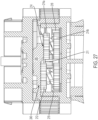
- the spice hopper 204 is shown having a clear outer housing 250 that contains the two grinders 224 and 226. Each grinder is housed in a separate chamber 253a and 253b separated by a clear wall 252. Above the housing 250 and formed as part of the bottom gearbox housing 242, are a pair of doors 254 and 256 that allow materials to be added to each chamber 253a and 253b, respectively. Below the grinders 224 and 226 are thumbscrews 270 and 272 that adjust the grinders to control how fine or coarse the material is ground.
- Fig. 29 shows the right door 256 in the open position.
- the door 256 pivots about an axle 257 and includes a stop 258 to prevent the door from opening too much and tab 260 which provides a light interference to keep the door in place when closed.
Landscapes
- Engineering & Computer Science (AREA)
- Mechanical Engineering (AREA)
- Food Science & Technology (AREA)
- Food-Manufacturing Devices (AREA)
- Devices For Opening Bottles Or Cans (AREA)
- Table Equipment (AREA)
Claims (2)
- Modulares Küchengerät, umfassend:einen Antriebskopf (10), der einen Motor (70) mit einer Antriebswelle (74) aufweist;einen Mahlwerkaufsatz (20), der abnehmbar an dem Antriebskopf (10) befestigt ist, wobei der Mahlwerkaufsatz (20) eine Befestigungswelle (208) aufweist, die mit der Antriebswelle (74) des Motors (70) verbunden ist;dadurch gekennzeichnet, dass:die Befestigungswelle (208) mit einer Antriebsachse (210) verbunden ist, die operativ mit einem ersten Rutschrad (212) und einem zweiten Rutschrad (214) verbunden ist;das erste Rutschrad (212) mit einem ersten Mahlwerk (224) verbunden ist und das zweite Rutschrad (214) mit einem zweiten Mahlwerk (226) verbunden ist;das Gerät weiter einen Trichter (204) umfasst, der zwei unterschiedliche Materialien zum Mahlen aufnehmen kann;wobei in einem ersten Betriebsmodus das erste Rutschrad (212) Leistung auf das erste Mahlwerk (224) überträgt und das zweite Rutschrad (214) keine Leistung auf das zweite Mahlwerk (226) überträgt und in einem zweiten Betriebsmodus das zweite Rutschrad (214) Leistung auf das zweite Mahlwerk (226) überträgt und das erste Rutschrad (212) keine Leistung auf das erste Mahlwerk (224) überträgt;wobei das erste und zweite Rutschrad (212, 214) jeweils ein oberes Zahnrad (212a, 214a) und ein unteres Zahnrad (212b, 214b) aufweisen, die selektiv relativ zueinander drehen können, wobei das obere Zahnrad ( 212a, 214a) und das untere Zahnrad (212b, 214b) jedes des ersten und zweiten Rutschrads (212, 214) Rampen (230a, 230b) aufweisen, die das obere Zahnrad (212a, 214a) vom unteren Zahnrad (212b, 214b) trennen, damit sie sich relativ zueinander drehen können;wobei der Mahlwerkaufsatz (20) weiter einen Gewürzwähler (202) umfasst, der über eines von dem ersten Rutschrad (212) oder dem zweiten Rutschrad (214) beweglich ist, um zu verhindern, dass sich das obere Zahnrad (212a, 214a) vom unteren Zahnrad (212b, 214b) trennt, wobei der Gewürzwähler (202) ein Gewürzwählrad (244) umfasst, das einen Vorsprung (246) aufweist, der von der Unterseite des Gewürzwählrads (244) hervorsteht, der so konfiguriert ist, dass eine Drehung des Gewürzwählrads (244) bewirkt, dass der Vorsprung (246) über einem der Rutschräder (212, 214) sitzt, wodurch verhindert wird, dass sich eines der oberen Zahnräder (212a, 214a) von seinem entsprechenden unteren Zahnrad (212b, 214b) trennt, wobei ohne eine solche Trennung das obere Zahnrad (212a, 214a) seine Drehung auf das untere Zahnrad (212b, 214b) und letztendlich auf das Mahlwerk (224, 226) überträgt, und daher, abhängig davon, über welchem Rutschrad (212, 214) der Vorsprung (246) sitzt, der Gewürzwähler (202) bestimmt, welches der Mahlwerke (224, 226) in Betrieb ist.
- Modulares Küchengerät nach einem vorstehenden Anspruch, wobei sich der Motor (70) im ersten und zweiten Betriebsmodus in die gleiche Richtung dreht.
Priority Applications (1)
| Application Number | Priority Date | Filing Date | Title |
|---|---|---|---|
| EP24195434.6A EP4442637A3 (de) | 2021-02-04 | 2022-01-28 | Modulares handküchengerät |
Applications Claiming Priority (1)
| Application Number | Priority Date | Filing Date | Title |
|---|---|---|---|
| US17/167,150 US12262849B2 (en) | 2021-02-04 | 2021-02-04 | Modular hand-held kitchen applicance |
Related Child Applications (2)
| Application Number | Title | Priority Date | Filing Date |
|---|---|---|---|
| EP24195434.6A Division-Into EP4442637A3 (de) | 2021-02-04 | 2022-01-28 | Modulares handküchengerät |
| EP24195434.6A Division EP4442637A3 (de) | 2021-02-04 | 2022-01-28 | Modulares handküchengerät |
Publications (3)
| Publication Number | Publication Date |
|---|---|
| EP4049564A2 EP4049564A2 (de) | 2022-08-31 |
| EP4049564A3 EP4049564A3 (de) | 2022-09-21 |
| EP4049564B1 true EP4049564B1 (de) | 2024-09-25 |
Family
ID=80122285
Family Applications (2)
| Application Number | Title | Priority Date | Filing Date |
|---|---|---|---|
| EP22153818.4A Active EP4049564B1 (de) | 2021-02-04 | 2022-01-28 | Modulares handgeführtes küchengerät |
| EP24195434.6A Pending EP4442637A3 (de) | 2021-02-04 | 2022-01-28 | Modulares handküchengerät |
Family Applications After (1)
| Application Number | Title | Priority Date | Filing Date |
|---|---|---|---|
| EP24195434.6A Pending EP4442637A3 (de) | 2021-02-04 | 2022-01-28 | Modulares handküchengerät |
Country Status (2)
| Country | Link |
|---|---|
| US (1) | US12262849B2 (de) |
| EP (2) | EP4049564B1 (de) |
Families Citing this family (12)
| Publication number | Priority date | Publication date | Assignee | Title |
|---|---|---|---|---|
| USD1023705S1 (en) * | 2021-06-18 | 2024-04-23 | Zhuhai Kelitong Electronic Co., Ltd. | Electric wine opener |
| USD998411S1 (en) * | 2021-06-30 | 2023-09-12 | Zhuhai Royal Electric Appliance Co., Ltd | Food blender |
| USD1005073S1 (en) * | 2021-09-02 | 2023-11-21 | Dongguan Hehe Plastic Electronics Co., Ltd. | Electric wine opener |
| US20230276993A1 (en) * | 2022-03-01 | 2023-09-07 | Whirlpool Corporation | Immersion blender |
| USD1050799S1 (en) * | 2022-07-08 | 2024-11-12 | Sharkninja Operating Llc | Immersion blender |
| USD1058292S1 (en) * | 2022-09-07 | 2025-01-21 | Ningbo Telent Technology Co., Ltd. | Electric stirrer |
| USD1083491S1 (en) * | 2022-09-19 | 2025-07-15 | Whirlpool Corporation | Immersion blender |
| US12564290B2 (en) * | 2023-01-12 | 2026-03-03 | Whirlpool Corporation | Magnetic compass interlock vessel detection and vessel recognition device |
| US20250072463A1 (en) * | 2023-08-30 | 2025-03-06 | Sharkninja Operating Llc | Plunger retention assembly for a micro-puree machine |
| USD1070483S1 (en) * | 2023-10-15 | 2025-04-15 | Shenzhen Xiaohongbao Technology Co., Ltd. | Milk frother |
| WO2025085879A1 (en) * | 2023-10-20 | 2025-04-24 | G&E Innovations Inc. | Gear mechanism for grinders |
| US12201241B1 (en) * | 2024-08-16 | 2025-01-21 | Guy Levi | Electric spice grinder with digital thermometer |
Family Cites Families (77)
| Publication number | Priority date | Publication date | Assignee | Title |
|---|---|---|---|---|
| CA931373A (en) | 1971-02-22 | 1973-08-07 | L. Messiha Habib | Automatic bottle opener |
| US3827641A (en) * | 1972-09-29 | 1974-08-06 | Gullaskrufs Glasbruks Ab | Multi-purpose grinding mill |
| DE2817044C3 (de) | 1978-04-19 | 1982-01-28 | Braun Ag, 6000 Frankfurt | Elektrischer Haushalts-Mischzerkleinerer |
| US4709865A (en) | 1982-12-30 | 1987-12-01 | Bounds William E | Dual condiment mill |
| AT380222B (de) | 1984-06-01 | 1986-04-25 | Philips Nv | Korkenzieher |
| GB8528988D0 (en) | 1985-11-25 | 1986-01-02 | Cole & Mason Ltd | Condiment grinder |
| IT209821Z2 (it) * | 1987-01-15 | 1988-11-04 | Tedioli Pier Giorgio | Apparecchio elettrico a macina, per macinare pepe o sale. |
| US5095778A (en) | 1991-02-12 | 1992-03-17 | Sandor Bocsi | Electric cork screw |
| US5088652A (en) | 1991-03-01 | 1992-02-18 | Chen Tzung Wen | Hand pepper grinder |
| US5079975A (en) | 1991-06-27 | 1992-01-14 | Spencer Jr Frank W | Automatic corkscrew |
| US5351579A (en) | 1993-05-20 | 1994-10-04 | Robert Metz | Rechargeable electric corkscrew |
| US5724869A (en) | 1995-06-08 | 1998-03-10 | May; Robert A. | Automatic cork remover |
| GB9702913D0 (en) | 1997-02-13 | 1997-04-02 | Dualit Ltd | Bottle opening apparatus |
| DE19820915A1 (de) | 1998-05-09 | 1999-11-18 | Braun Gmbh | Handmixer |
| AU1394000A (en) | 1998-11-16 | 2000-06-05 | Xanthos Menelaou | Multi-compartment mill |
| GB2348638B (en) | 1999-04-08 | 2001-02-28 | Kwok Kuen So | Corkscrew |
| CH696319A5 (de) | 1999-09-24 | 2007-04-13 | Weibel Innovate Gmbh | Kapselschneider. |
| DE10022131C1 (de) | 2000-05-06 | 2001-09-13 | Braun Gmbh | Kupplungsvorrichtung für eine Küchenmaschine |
| DE10114373A1 (de) | 2001-03-23 | 2002-10-10 | Braun Gmbh | Hand- oder Stabmixer mit Kupplungsvorrichtung |
| US6609821B2 (en) | 2001-04-13 | 2003-08-26 | Sunbeam Products, Inc. | Blender base with food processor capabilities |
| GB0113643D0 (en) | 2001-06-05 | 2001-07-25 | Theresa Internat Ltd | Electric cork screw |
| US6719450B2 (en) | 2002-04-19 | 2004-04-13 | Bonjour, Incorporated | Processing tool attachments for a food mixing device |
| US20030217621A1 (en) | 2002-05-24 | 2003-11-27 | Su Chiou Jing | Corkscrew |
| TW563694U (en) | 2002-06-17 | 2003-11-21 | Taiwan Wan Nien Electric Appli | Power-driven corkscrew |
| US20040083783A1 (en) | 2002-11-01 | 2004-05-06 | Brandalise Juan Carlos | Key-ring from a photographic roll film casing |
| US6962302B2 (en) | 2003-10-14 | 2005-11-08 | Shun-I Cheng | Combination of pepper mill and salt mill |
| FR2860698B1 (fr) | 2003-10-14 | 2005-12-09 | Seb Sa | Pied de mixage et mixeur menager de type plongeant muni d'un tel pied de mixage. |
| FR2861568B1 (fr) | 2003-11-04 | 2005-12-30 | Seb Sa | Boitier d'appareil electromenager de preparation culinaire prevu pour etre tenu a la main selon differentes positions |
| DE202005000438U1 (de) | 2005-01-13 | 2005-10-06 | Richter, Siegfried | Elektrischer Korkenzieher |
| EP1707091A1 (de) | 2005-03-31 | 2006-10-04 | Duo Yeu Metal Co., Ltd. | Doppelfunktions-Gewürzmühle |
| ES1060846Y (es) | 2005-07-28 | 2006-03-01 | Sammic Sl | Dispositivo acoplador liberable entre un brazo triturador y/o batidor y un bloque motor en maquinas trituradoras electroportatiles |
| DE102005038919A1 (de) | 2005-08-17 | 2007-03-15 | BSH Bosch und Siemens Hausgeräte GmbH | Elektromotorisches Küchengerät mit elektrischer oder elektronischer Verriegelung |
| US7845537B2 (en) | 2006-01-31 | 2010-12-07 | Ethicon Endo-Surgery, Inc. | Surgical instrument having recording capabilities |
| US7380737B2 (en) | 2006-03-22 | 2008-06-03 | Duo Yeu Metal. Col, Ltd. | Electric seasoning mill |
| KR101316116B1 (ko) | 2006-06-28 | 2013-10-11 | 서울바이오시스 주식회사 | 제너 다이오드를 구비하는 발광소자 및 그 제조 방법 |
| DE502007004736D1 (de) * | 2006-07-13 | 2010-09-23 | Pi Design Ag | Kombinierte salz- und pfeffermühle |
| US7533838B2 (en) | 2007-03-30 | 2009-05-19 | Daka Research Inc. (Br. Virg.Isl Corp.) | Spice mill |
| DE202007007947U1 (de) | 2007-06-06 | 2007-11-08 | Samson Bright Industrial Co. Ltd., Hunghom | Doppelgewürzmühle |
| US20130202401A1 (en) | 2007-07-02 | 2013-08-08 | Isaac Taitler | Method and Device for variable motion and applications using Interchangeable Heads |
| US7637447B2 (en) | 2007-09-05 | 2009-12-29 | Samson Bright Industrial Company Limited | Dual condiment grinder |
| FR2930881B1 (fr) | 2008-05-07 | 2010-05-21 | Seb Sa | Appareil electromenager de preparation culinaire prevu pour etre tenu a la main muni d'un element guide cordon |
| EP2193734A1 (de) | 2008-12-05 | 2010-06-09 | Koninklijke Philips Electronics N.V. | Kupplungsanordnung, Küchengerät und Handmixer |
| US7708220B1 (en) | 2008-12-16 | 2010-05-04 | Samson Bright Industrial Company Limited | Electric dual condiment grinder |
| EP2198761A1 (de) | 2008-12-18 | 2010-06-23 | Koninklijke Philips Electronics N.V. | Abgabesystem für ein Küchenutensil |
| GB2467756B (en) | 2009-02-12 | 2011-01-12 | Chun Ming Cheung | Electric corkscrew |
| FR2953208B1 (fr) | 2009-11-27 | 2011-11-18 | Jensen Ind Ltd | Appareil menager multifonction associant une poignee motorisee autonome en energie et un jeu d'instruments interchangeables |
| EP2547244B1 (de) | 2010-03-18 | 2016-09-07 | Breville PTY Limited | Kombinations-entsafter und -mischer |
| ES2373176B1 (es) | 2010-06-10 | 2012-12-10 | Electrodomésticos Taurus, S.L. | Batidora de mano con cabezal separable. |
| ES2384925B1 (es) | 2010-12-15 | 2013-05-20 | Electrodomésticos Taurus, S.L. | Batidora de mano con cabezal de trabajo separable. |
| US8757529B2 (en) * | 2011-03-23 | 2014-06-24 | Samson Bright Industrial Company Limited | Condiment grinder |
| WO2013067351A2 (en) | 2011-11-03 | 2013-05-10 | Robert Bosch Gmbh | Corkscrew assembly for use with a power tool |
| FR2986410B1 (fr) | 2012-02-06 | 2014-02-21 | Seb Sa | Appareil electromenager de preparation culinaire prevu pour etre tenu a la main comportant un element de facade rapporte |
| EP2671485A1 (de) | 2012-06-08 | 2013-12-11 | Koninklijke Philips N.V. | Schnittstelle für eine tragbare Küchenanwendung |
| WO2013181692A1 (en) | 2012-06-08 | 2013-12-12 | Breville Pty Limited | Stick mixer driven food processor |
| DE202012006296U1 (de) | 2012-06-29 | 2012-08-09 | Cedomir Repac | Gewürzmühle mit Verriegelungsmittel |
| CN202880808U (zh) | 2012-09-07 | 2013-04-17 | 东莞精博电子科技有限公司 | 全自动开瓶器 |
| AU2013334468B2 (en) | 2012-10-26 | 2017-08-31 | Breville Pty Limited | Potato ricer |
| US20140123813A1 (en) | 2012-11-06 | 2014-05-08 | Hamilton Beach Brands, Inc. | Combination Can and Bottle Opener |
| EP2956040B1 (de) | 2013-02-15 | 2019-08-21 | BaByliss Faco sprl | Antriebseinheit für teile eines elektrohaushaltsgeräts |
| US9261168B2 (en) | 2013-06-14 | 2016-02-16 | Heng-De Yang | Dual condiment grinder |
| CN103315650B (zh) | 2013-06-27 | 2015-11-18 | 惠阳亚伦塑胶电器实业有限公司 | 一种双速手持搅拌机 |
| CN105358026A (zh) | 2013-06-28 | 2016-02-24 | 皇家飞利浦有限公司 | 马达单元、工具单元和手持搅拌器 |
| US9637367B1 (en) | 2013-12-30 | 2017-05-02 | Karl Peter Arnold | Combined cork and twist cap remover |
| US9516975B2 (en) * | 2014-04-18 | 2016-12-13 | King's Flair Development Ltd. | Condiment mill |
| CN104083101B (zh) | 2014-06-30 | 2017-06-16 | 惠阳亚伦塑胶电器实业有限公司 | 一种手持搅拌机 |
| CN104305893B (zh) | 2014-10-08 | 2017-09-22 | 惠阳亚伦塑胶电器实业有限公司 | 一种手持搅拌机 |
| CN104340937B (zh) | 2014-10-17 | 2016-08-24 | 宋骁先 | 一种多功能电动开瓶器 |
| US9693657B2 (en) | 2015-01-22 | 2017-07-04 | Helen Of Troy Limited | Spice mill |
| RU2689044C2 (ru) | 2015-02-26 | 2019-05-23 | Конинклейке Филипс Н.В. | Обнаружение инструмента для кухонных приборов |
| WO2016172836A1 (zh) | 2015-04-28 | 2016-11-03 | 尚平 | 一种电动开瓶器 |
| WO2017018624A1 (ko) | 2015-07-29 | 2017-02-02 | 주식회사 하우스일렉 | 믹서기 겸용 진공 형성 장치 |
| CN105056822A (zh) | 2015-09-07 | 2015-11-18 | 惠阳亚伦塑胶电器实业有限公司 | 手持搅拌机 |
| US10328562B2 (en) | 2016-12-23 | 2019-06-25 | Tti (Macao Commercial Offshore) Limited | Handheld kitchen appliance assembly |
| KR20170033818A (ko) | 2017-01-23 | 2017-03-27 | 주식회사 하우스일렉 | 결합되는 조리 기기의 식별이 가능한 믹서기 |
| US20180215599A1 (en) | 2017-01-27 | 2018-08-02 | Brookstone Purchasing, Inc. | Automatic bottle opener with automatic sensing |
| FR3083688B1 (fr) | 2018-07-13 | 2020-06-19 | Seb S.A. | Systeme de ventilation d'un appareil electro-menager portatif de traitement de preparations alimentaires, de type mixeur / batteur |
| WO2020118224A1 (en) | 2018-12-06 | 2020-06-11 | Columbia Insurance Company | Modular appliance apparatus configured for multiple attachments |
-
2021
- 2021-02-04 US US17/167,150 patent/US12262849B2/en active Active
-
2022
- 2022-01-28 EP EP22153818.4A patent/EP4049564B1/de active Active
- 2022-01-28 EP EP24195434.6A patent/EP4442637A3/de active Pending
Also Published As
| Publication number | Publication date |
|---|---|
| EP4049564A3 (de) | 2022-09-21 |
| EP4442637A2 (de) | 2024-10-09 |
| EP4049564A2 (de) | 2022-08-31 |
| EP4442637A3 (de) | 2024-12-25 |
| US20220240723A1 (en) | 2022-08-04 |
| US12262849B2 (en) | 2025-04-01 |
Similar Documents
| Publication | Publication Date | Title |
|---|---|---|
| US12262849B2 (en) | Modular hand-held kitchen applicance | |
| US20090032627A1 (en) | Spice Grinder | |
| US10328562B2 (en) | Handheld kitchen appliance assembly | |
| US11903524B2 (en) | Motor driven food processing system | |
| CN109645850B (zh) | 电动运行的厨用机器 | |
| CN102892344B (zh) | 组合榨汁机-搅拌机 | |
| WO2008047106A1 (en) | A food processor | |
| EP1449471B1 (de) | Verbesserung in einer elektrischen Pfeffermühle | |
| US20230276993A1 (en) | Immersion blender | |
| US20230277004A1 (en) | Cordless food processor | |
| US20240090703A1 (en) | Cordless blending appliance | |
| EP1791455A1 (de) | Kabelloses rührgerät | |
| US7077347B1 (en) | Electric pepper mill | |
| WO2016118350A1 (en) | Spice mill | |
| US11992161B2 (en) | Sound enclosure system for food blender | |
| US5685501A (en) | Portable electric spice mill | |
| US7228991B2 (en) | Condiment dispenser | |
| CN113440029A (zh) | 具有食物加工机和家用混合装置的系统 | |
| JP3206207U (ja) | 調理用粉砕器 | |
| US20250151941A1 (en) | Cordless citrus juicer | |
| CN219270724U (zh) | 一种研磨设备 | |
| CN209202919U (zh) | 料理设备 | |
| KR20170001180U (ko) | 자성체를 이용하여 동작이 제어되는 요리 기기 | |
| KR20180119855A (ko) | 동력 전달 구조를 갖는 식품 가공 장치 | |
| KR100228199B1 (ko) | 주서/믹서의 회전식 스위치 |
Legal Events
| Date | Code | Title | Description |
|---|---|---|---|
| PUAI | Public reference made under article 153(3) epc to a published international application that has entered the european phase |
Free format text: ORIGINAL CODE: 0009012 |
|
| STAA | Information on the status of an ep patent application or granted ep patent |
Free format text: STATUS: THE APPLICATION HAS BEEN PUBLISHED |
|
| PUAL | Search report despatched |
Free format text: ORIGINAL CODE: 0009013 |
|
| AK | Designated contracting states |
Kind code of ref document: A2 Designated state(s): AL AT BE BG CH CY CZ DE DK EE ES FI FR GB GR HR HU IE IS IT LI LT LU LV MC MK MT NL NO PL PT RO RS SE SI SK SM TR |
|
| AK | Designated contracting states |
Kind code of ref document: A3 Designated state(s): AL AT BE BG CH CY CZ DE DK EE ES FI FR GB GR HR HU IE IS IT LI LT LU LV MC MK MT NL NO PL PT RO RS SE SI SK SM TR |
|
| RIC1 | Information provided on ipc code assigned before grant |
Ipc: B67B 7/04 20060101ALI20220816BHEP Ipc: A47J 42/46 20060101ALI20220816BHEP Ipc: A47J 43/06 20060101AFI20220816BHEP |
|
| STAA | Information on the status of an ep patent application or granted ep patent |
Free format text: STATUS: REQUEST FOR EXAMINATION WAS MADE |
|
| 17P | Request for examination filed |
Effective date: 20230315 |
|
| RBV | Designated contracting states (corrected) |
Designated state(s): AL AT BE BG CH CY CZ DE DK EE ES FI FR GB GR HR HU IE IS IT LI LT LU LV MC MK MT NL NO PL PT RO RS SE SI SK SM TR |
|
| STAA | Information on the status of an ep patent application or granted ep patent |
Free format text: STATUS: EXAMINATION IS IN PROGRESS |
|
| 17Q | First examination report despatched |
Effective date: 20230626 |
|
| GRAP | Despatch of communication of intention to grant a patent |
Free format text: ORIGINAL CODE: EPIDOSNIGR1 |
|
| STAA | Information on the status of an ep patent application or granted ep patent |
Free format text: STATUS: GRANT OF PATENT IS INTENDED |
|
| INTG | Intention to grant announced |
Effective date: 20231129 |
|
| RIN1 | Information on inventor provided before grant (corrected) |
Inventor name: LANGFORD, DANIEL Inventor name: CROSS, ANDREW Inventor name: BASKAR, ASHOK Inventor name: NOHE, KENDALL Inventor name: DOYLE, MICHAEL C. Inventor name: LANDIS, THOMAS Inventor name: SERGYEYENKO, OLEKSIY |
|
| GRAJ | Information related to disapproval of communication of intention to grant by the applicant or resumption of examination proceedings by the epo deleted |
Free format text: ORIGINAL CODE: EPIDOSDIGR1 |
|
| STAA | Information on the status of an ep patent application or granted ep patent |
Free format text: STATUS: EXAMINATION IS IN PROGRESS |
|
| GRAP | Despatch of communication of intention to grant a patent |
Free format text: ORIGINAL CODE: EPIDOSNIGR1 |
|
| STAA | Information on the status of an ep patent application or granted ep patent |
Free format text: STATUS: GRANT OF PATENT IS INTENDED |
|
| INTC | Intention to grant announced (deleted) | ||
| INTG | Intention to grant announced |
Effective date: 20240418 |
|
| GRAS | Grant fee paid |
Free format text: ORIGINAL CODE: EPIDOSNIGR3 |
|
| GRAA | (expected) grant |
Free format text: ORIGINAL CODE: 0009210 |
|
| STAA | Information on the status of an ep patent application or granted ep patent |
Free format text: STATUS: THE PATENT HAS BEEN GRANTED |
|
| AK | Designated contracting states |
Kind code of ref document: B1 Designated state(s): AL AT BE BG CH CY CZ DE DK EE ES FI FR GB GR HR HU IE IS IT LI LT LU LV MC MK MT NL NO PL PT RO RS SE SI SK SM TR |
|
| REG | Reference to a national code |
Ref country code: GB Ref legal event code: FG4D |
|
| REG | Reference to a national code |
Ref country code: CH Ref legal event code: EP |
|
| REG | Reference to a national code |
Ref country code: DE Ref legal event code: R096 Ref document number: 602022006267 Country of ref document: DE |
|
| REG | Reference to a national code |
Ref country code: IE Ref legal event code: FG4D |
|
| REG | Reference to a national code |
Ref country code: LT Ref legal event code: MG9D |
|
| PG25 | Lapsed in a contracting state [announced via postgrant information from national office to epo] |
Ref country code: NO Free format text: LAPSE BECAUSE OF FAILURE TO SUBMIT A TRANSLATION OF THE DESCRIPTION OR TO PAY THE FEE WITHIN THE PRESCRIBED TIME-LIMIT Effective date: 20241225 |
|
| PG25 | Lapsed in a contracting state [announced via postgrant information from national office to epo] |
Ref country code: GR Free format text: LAPSE BECAUSE OF FAILURE TO SUBMIT A TRANSLATION OF THE DESCRIPTION OR TO PAY THE FEE WITHIN THE PRESCRIBED TIME-LIMIT Effective date: 20241226 Ref country code: FI Free format text: LAPSE BECAUSE OF FAILURE TO SUBMIT A TRANSLATION OF THE DESCRIPTION OR TO PAY THE FEE WITHIN THE PRESCRIBED TIME-LIMIT Effective date: 20240925 |
|
| PG25 | Lapsed in a contracting state [announced via postgrant information from national office to epo] |
Ref country code: BG Free format text: LAPSE BECAUSE OF FAILURE TO SUBMIT A TRANSLATION OF THE DESCRIPTION OR TO PAY THE FEE WITHIN THE PRESCRIBED TIME-LIMIT Effective date: 20240925 |
|
| PG25 | Lapsed in a contracting state [announced via postgrant information from national office to epo] |
Ref country code: LV Free format text: LAPSE BECAUSE OF FAILURE TO SUBMIT A TRANSLATION OF THE DESCRIPTION OR TO PAY THE FEE WITHIN THE PRESCRIBED TIME-LIMIT Effective date: 20240925 |
|
| PG25 | Lapsed in a contracting state [announced via postgrant information from national office to epo] |
Ref country code: RS Free format text: LAPSE BECAUSE OF FAILURE TO SUBMIT A TRANSLATION OF THE DESCRIPTION OR TO PAY THE FEE WITHIN THE PRESCRIBED TIME-LIMIT Effective date: 20241225 |
|
| REG | Reference to a national code |
Ref country code: NL Ref legal event code: MP Effective date: 20240925 |
|
| PG25 | Lapsed in a contracting state [announced via postgrant information from national office to epo] |
Ref country code: RS Free format text: LAPSE BECAUSE OF FAILURE TO SUBMIT A TRANSLATION OF THE DESCRIPTION OR TO PAY THE FEE WITHIN THE PRESCRIBED TIME-LIMIT Effective date: 20241225 Ref country code: NO Free format text: LAPSE BECAUSE OF FAILURE TO SUBMIT A TRANSLATION OF THE DESCRIPTION OR TO PAY THE FEE WITHIN THE PRESCRIBED TIME-LIMIT Effective date: 20241225 Ref country code: LV Free format text: LAPSE BECAUSE OF FAILURE TO SUBMIT A TRANSLATION OF THE DESCRIPTION OR TO PAY THE FEE WITHIN THE PRESCRIBED TIME-LIMIT Effective date: 20240925 Ref country code: GR Free format text: LAPSE BECAUSE OF FAILURE TO SUBMIT A TRANSLATION OF THE DESCRIPTION OR TO PAY THE FEE WITHIN THE PRESCRIBED TIME-LIMIT Effective date: 20241226 Ref country code: FI Free format text: LAPSE BECAUSE OF FAILURE TO SUBMIT A TRANSLATION OF THE DESCRIPTION OR TO PAY THE FEE WITHIN THE PRESCRIBED TIME-LIMIT Effective date: 20240925 Ref country code: BG Free format text: LAPSE BECAUSE OF FAILURE TO SUBMIT A TRANSLATION OF THE DESCRIPTION OR TO PAY THE FEE WITHIN THE PRESCRIBED TIME-LIMIT Effective date: 20240925 |
|
| REG | Reference to a national code |
Ref country code: AT Ref legal event code: MK05 Ref document number: 1725909 Country of ref document: AT Kind code of ref document: T Effective date: 20240925 |
|
| PG25 | Lapsed in a contracting state [announced via postgrant information from national office to epo] |
Ref country code: NL Free format text: LAPSE BECAUSE OF FAILURE TO SUBMIT A TRANSLATION OF THE DESCRIPTION OR TO PAY THE FEE WITHIN THE PRESCRIBED TIME-LIMIT Effective date: 20240925 |
|
| PG25 | Lapsed in a contracting state [announced via postgrant information from national office to epo] |
Ref country code: PT Free format text: LAPSE BECAUSE OF FAILURE TO SUBMIT A TRANSLATION OF THE DESCRIPTION OR TO PAY THE FEE WITHIN THE PRESCRIBED TIME-LIMIT Effective date: 20250127 Ref country code: IS Free format text: LAPSE BECAUSE OF FAILURE TO SUBMIT A TRANSLATION OF THE DESCRIPTION OR TO PAY THE FEE WITHIN THE PRESCRIBED TIME-LIMIT Effective date: 20250125 |
|
| PG25 | Lapsed in a contracting state [announced via postgrant information from national office to epo] |
Ref country code: RO Free format text: LAPSE BECAUSE OF FAILURE TO SUBMIT A TRANSLATION OF THE DESCRIPTION OR TO PAY THE FEE WITHIN THE PRESCRIBED TIME-LIMIT Effective date: 20240925 Ref country code: SM Free format text: LAPSE BECAUSE OF FAILURE TO SUBMIT A TRANSLATION OF THE DESCRIPTION OR TO PAY THE FEE WITHIN THE PRESCRIBED TIME-LIMIT Effective date: 20240925 |
|
| PG25 | Lapsed in a contracting state [announced via postgrant information from national office to epo] |
Ref country code: ES Free format text: LAPSE BECAUSE OF FAILURE TO SUBMIT A TRANSLATION OF THE DESCRIPTION OR TO PAY THE FEE WITHIN THE PRESCRIBED TIME-LIMIT Effective date: 20240925 |
|
| PG25 | Lapsed in a contracting state [announced via postgrant information from national office to epo] |
Ref country code: AT Free format text: LAPSE BECAUSE OF FAILURE TO SUBMIT A TRANSLATION OF THE DESCRIPTION OR TO PAY THE FEE WITHIN THE PRESCRIBED TIME-LIMIT Effective date: 20240925 Ref country code: EE Free format text: LAPSE BECAUSE OF FAILURE TO SUBMIT A TRANSLATION OF THE DESCRIPTION OR TO PAY THE FEE WITHIN THE PRESCRIBED TIME-LIMIT Effective date: 20240925 |
|
| PG25 | Lapsed in a contracting state [announced via postgrant information from national office to epo] |
Ref country code: CZ Free format text: LAPSE BECAUSE OF FAILURE TO SUBMIT A TRANSLATION OF THE DESCRIPTION OR TO PAY THE FEE WITHIN THE PRESCRIBED TIME-LIMIT Effective date: 20240925 Ref country code: PL Free format text: LAPSE BECAUSE OF FAILURE TO SUBMIT A TRANSLATION OF THE DESCRIPTION OR TO PAY THE FEE WITHIN THE PRESCRIBED TIME-LIMIT Effective date: 20240925 |
|
| PG25 | Lapsed in a contracting state [announced via postgrant information from national office to epo] |
Ref country code: IT Free format text: LAPSE BECAUSE OF FAILURE TO SUBMIT A TRANSLATION OF THE DESCRIPTION OR TO PAY THE FEE WITHIN THE PRESCRIBED TIME-LIMIT Effective date: 20240925 Ref country code: SK Free format text: LAPSE BECAUSE OF FAILURE TO SUBMIT A TRANSLATION OF THE DESCRIPTION OR TO PAY THE FEE WITHIN THE PRESCRIBED TIME-LIMIT Effective date: 20240925 |
|
| REG | Reference to a national code |
Ref country code: DE Ref legal event code: R097 Ref document number: 602022006267 Country of ref document: DE |
|
| PG25 | Lapsed in a contracting state [announced via postgrant information from national office to epo] |
Ref country code: DK Free format text: LAPSE BECAUSE OF FAILURE TO SUBMIT A TRANSLATION OF THE DESCRIPTION OR TO PAY THE FEE WITHIN THE PRESCRIBED TIME-LIMIT Effective date: 20240925 |
|
| PLBE | No opposition filed within time limit |
Free format text: ORIGINAL CODE: 0009261 |
|
| STAA | Information on the status of an ep patent application or granted ep patent |
Free format text: STATUS: NO OPPOSITION FILED WITHIN TIME LIMIT |
|
| REG | Reference to a national code |
Ref country code: CH Ref legal event code: PL |
|
| 26N | No opposition filed |
Effective date: 20250626 |
|
| PG25 | Lapsed in a contracting state [announced via postgrant information from national office to epo] |
Ref country code: SE Free format text: LAPSE BECAUSE OF FAILURE TO SUBMIT A TRANSLATION OF THE DESCRIPTION OR TO PAY THE FEE WITHIN THE PRESCRIBED TIME-LIMIT Effective date: 20240925 |
|
| PG25 | Lapsed in a contracting state [announced via postgrant information from national office to epo] |
Ref country code: LU Free format text: LAPSE BECAUSE OF NON-PAYMENT OF DUE FEES Effective date: 20250128 Ref country code: MC Free format text: LAPSE BECAUSE OF FAILURE TO SUBMIT A TRANSLATION OF THE DESCRIPTION OR TO PAY THE FEE WITHIN THE PRESCRIBED TIME-LIMIT Effective date: 20240925 |
|
| PG25 | Lapsed in a contracting state [announced via postgrant information from national office to epo] |
Ref country code: BE Free format text: LAPSE BECAUSE OF NON-PAYMENT OF DUE FEES Effective date: 20250131 |
|
| PG25 | Lapsed in a contracting state [announced via postgrant information from national office to epo] |
Ref country code: FR Free format text: LAPSE BECAUSE OF NON-PAYMENT OF DUE FEES Effective date: 20250131 |
|
| PG25 | Lapsed in a contracting state [announced via postgrant information from national office to epo] |
Ref country code: CH Free format text: LAPSE BECAUSE OF NON-PAYMENT OF DUE FEES Effective date: 20250131 |
|
| REG | Reference to a national code |
Ref country code: BE Ref legal event code: MM Effective date: 20250131 |
|
| PG25 | Lapsed in a contracting state [announced via postgrant information from national office to epo] |
Ref country code: HR Free format text: LAPSE BECAUSE OF FAILURE TO SUBMIT A TRANSLATION OF THE DESCRIPTION OR TO PAY THE FEE WITHIN THE PRESCRIBED TIME-LIMIT Effective date: 20240925 |
|
| PG25 | Lapsed in a contracting state [announced via postgrant information from national office to epo] |
Ref country code: IE Free format text: LAPSE BECAUSE OF NON-PAYMENT OF DUE FEES Effective date: 20250128 |
|
| PGFP | Annual fee paid to national office [announced via postgrant information from national office to epo] |
Ref country code: GB Payment date: 20260122 Year of fee payment: 5 |
|
| PGFP | Annual fee paid to national office [announced via postgrant information from national office to epo] |
Ref country code: DE Payment date: 20260120 Year of fee payment: 5 |