EP4048532B1 - Antirutschvorrichtung - Google Patents
Antirutschvorrichtung Download PDFInfo
- Publication number
- EP4048532B1 EP4048532B1 EP20879766.2A EP20879766A EP4048532B1 EP 4048532 B1 EP4048532 B1 EP 4048532B1 EP 20879766 A EP20879766 A EP 20879766A EP 4048532 B1 EP4048532 B1 EP 4048532B1
- Authority
- EP
- European Patent Office
- Prior art keywords
- arms
- skid device
- slip
- tyre
- wheel
- Prior art date
- Legal status (The legal status is an assumption and is not a legal conclusion. Google has not performed a legal analysis and makes no representation as to the accuracy of the status listed.)
- Active
Links
Images


Classifications
-
- B—PERFORMING OPERATIONS; TRANSPORTING
- B60—VEHICLES IN GENERAL
- B60C—VEHICLE TYRES; TYRE INFLATION; TYRE CHANGING; CONNECTING VALVES TO INFLATABLE ELASTIC BODIES IN GENERAL; DEVICES OR ARRANGEMENTS RELATED TO TYRES
- B60C27/00—Non-skid devices temporarily attachable to resilient tyres or resiliently-tyred wheels
- B60C27/02—Non-skid devices temporarily attachable to resilient tyres or resiliently-tyred wheels extending over restricted arcuate part of tread
- B60C27/023—Non-skid devices temporarily attachable to resilient tyres or resiliently-tyred wheels extending over restricted arcuate part of tread provided with radial arms for supporting the ground engaging parts on the wheel
-
- B—PERFORMING OPERATIONS; TRANSPORTING
- B60—VEHICLES IN GENERAL
- B60C—VEHICLE TYRES; TYRE INFLATION; TYRE CHANGING; CONNECTING VALVES TO INFLATABLE ELASTIC BODIES IN GENERAL; DEVICES OR ARRANGEMENTS RELATED TO TYRES
- B60C27/00—Non-skid devices temporarily attachable to resilient tyres or resiliently-tyred wheels
- B60C27/02—Non-skid devices temporarily attachable to resilient tyres or resiliently-tyred wheels extending over restricted arcuate part of tread
- B60C27/0207—Non-skid devices temporarily attachable to resilient tyres or resiliently-tyred wheels extending over restricted arcuate part of tread involving lugs or rings taking up wear, e.g. chain links, chain connectors
- B60C27/0223—Studded links, i.e. traction enhancing parts located on the link or inserted into the link
-
- B—PERFORMING OPERATIONS; TRANSPORTING
- B60—VEHICLES IN GENERAL
- B60C—VEHICLE TYRES; TYRE INFLATION; TYRE CHANGING; CONNECTING VALVES TO INFLATABLE ELASTIC BODIES IN GENERAL; DEVICES OR ARRANGEMENTS RELATED TO TYRES
- B60C27/00—Non-skid devices temporarily attachable to resilient tyres or resiliently-tyred wheels
- B60C27/02—Non-skid devices temporarily attachable to resilient tyres or resiliently-tyred wheels extending over restricted arcuate part of tread
- B60C27/0238—Non-skid devices temporarily attachable to resilient tyres or resiliently-tyred wheels extending over restricted arcuate part of tread provided with tensioning means
- B60C27/0246—Resilient pretension
-
- B—PERFORMING OPERATIONS; TRANSPORTING
- B60—VEHICLES IN GENERAL
- B60C—VEHICLE TYRES; TYRE INFLATION; TYRE CHANGING; CONNECTING VALVES TO INFLATABLE ELASTIC BODIES IN GENERAL; DEVICES OR ARRANGEMENTS RELATED TO TYRES
- B60C27/00—Non-skid devices temporarily attachable to resilient tyres or resiliently-tyred wheels
- B60C27/02—Non-skid devices temporarily attachable to resilient tyres or resiliently-tyred wheels extending over restricted arcuate part of tread
- B60C27/0261—Non-skid devices temporarily attachable to resilient tyres or resiliently-tyred wheels extending over restricted arcuate part of tread provided with fastening means
-
- B—PERFORMING OPERATIONS; TRANSPORTING
- B60—VEHICLES IN GENERAL
- B60C—VEHICLE TYRES; TYRE INFLATION; TYRE CHANGING; CONNECTING VALVES TO INFLATABLE ELASTIC BODIES IN GENERAL; DEVICES OR ARRANGEMENTS RELATED TO TYRES
- B60C27/00—Non-skid devices temporarily attachable to resilient tyres or resiliently-tyred wheels
- B60C27/02—Non-skid devices temporarily attachable to resilient tyres or resiliently-tyred wheels extending over restricted arcuate part of tread
- B60C27/04—Non-skid devices temporarily attachable to resilient tyres or resiliently-tyred wheels extending over restricted arcuate part of tread the ground-engaging part being rigid
Definitions
- This invention relates generally to an anti-skid device for use in connection with vehicle wheels to improve traction in snow and ice.
- it relates to an anti-skid device that may be easily and quickly mounted and removed, easily and securely fastened and may be adjusted to different wheel sizes.
- KR20040091223 disclose a snow chain device with an operating plate arranged in the outer centre of a tire and composed of a plurality of entrance passages arranged around the peripheral part, and a plurality of friction members, where a plurality of entrance members are connected with the other ends of the friction members and disposed to go into the entrance passages of the operating plate and a holding/releasing unit for holding and releasing the entrance member fitted into the operating plate by the forcible-inserting unit.
- EP 0 110 838 A1 discloses an anti-skid attachment for a vehicle wheel having a central ring placed on the wheel hub.
- the central ring is connected to lugs by radial arms.
- the lugs are intended to cut the ice or provide more bite on the snow and are shaped in such a way as to encircle the tyre sides.
- Each lug is provided with a prismatic end to the said central ring and connected with guide means provided with a recess to house and guide the end of any of the lugs.
- a spring controls the axial movements of each lug, caused by the deformation of the tyre.
- US 3 016 079 A discloses an anti-skid device with 5 arms, where cables are used for moving the arms for mounting and dismounting.
- FR 2 540 443 A3 discloses an anti-skid device with 6 arms, where tension springs are used for retaining the arms.
- US 2011/094643 A1 discloses an anti-skid device with 6 arms, where a linkage system is used for moving the arms.
- the linkage system is quite complicated and consists of many parts.
- the primary object of this invention is to provide an anti-skid device which is easy to mount and dismount from the wheel without the need of skills, physical strength or a separate tool.
- Another object of the invention is to provide an anti-skid device which is simple, compact and made of few parts.
- Another object of this invention is to provide an anti-skid device which can be mounted from the front face of the wheel and can be adapted to different wheel sizes.
- Another object of this invention is to provide an anti-skid device which remains fastened even if the wheel changes diameter due to the flattening of the tyre at the wheel-ground contact.
- Figs.1 and 2 show an anti-skid device 1 according to the invention. As shown the device 1 according to the invention consists of three arms 3.
- each arm 3 is an attachment point 7 to which anti-slip elements 2 are removably fastened by sleeve 10.
- the relationship between mount 7 and sleeve 10 allows the anti-slip elements 2 freedom to move in a single linear axis such that they may slide inwards (towards the centre of the wheel), but may not slide outwards beyond a fixed limit.
- a great advantage with this construction is that it allows the device to be fitted to a range of wheel diameters by adjusting the lengths of the arms 3.
- the arms 3 are held slidably by a hub 4 comprising a housing 6, backplate 30 and guides 27, 28.
- Handle 5 is part of the operating means used to operate the inwards or outwards movement of the arms 3 to facilitate device 1 being mounted onto a wheel. This will be described in more detail with reference to Fig.4 and Figs.7-9 .
- Fig.1 shows the device 1 with arms 3 fully extended prior to being mounted on the wheel while Fig.2 shows the device 1 fastened to the wheel.
- the handle 5 may be foldable/retractable and/or detachable from the device 1 when not in use.
- Fig.3 there is shown the anti-slip element 2.
- Each element 2 has a sleeve 10 that is connected to the outer end of the arm 3.
- Each anti-slip element 2 is composed of two identical and symmetrical parts with a gap between allowing in this way a greater coverage of the tyre with an anti-slip surface.
- Sleeve 10 slidably receives the attachment point 7 of the arm 3.
- attachment point 7 is wider than the majority of arm 3 and equipped with a flange 11 at its extremity.
- sleeve 10 assembles to arm 3 below attachment point 7, before sliding outwards until it is stopped by flange 11.
- sleeve 10 and anti-slip element 2 are free to slide inwards but may not slide outwards due to the limiting effect of flange 11. It is also possible to create sleeve 10 with a partially closed end, such that it is this partially closed end that limits the outward movement of sleeve 10 in relation to arm 3. In this case flange 11 would not be required.
- This limited sliding interaction between anti-slip element 2 and arm 3 is important, in that it ensures that the upwards radial force created as the car drives over anti-slip element 2 is not transferred to arm 3 and thus to housing 6.
- anti-slip element 2 is free to follow the depression of the tyre created as the car drives over anti-slip element 2 and will return outwards to the limit of its travel once the weight of the car is removed from anti-slip element 2 and the tyre retakes its original form once more.
- Each anti-slip element 2 is equipped with multiple raised grip details 8 irregularly spaced, both, in the inner and the outer surfaces to increase friction with the ground, and to prevent any circumferential movement of the anti-slip components along the tyre tread.
- grip details 8 take the form of protuberances, but may also take the form of holes or local areas formed from a high friction material. Circumferential movement prevention is further enforced by the curved shape 12 of the left and right parts of the anti-slip element 2. An additional benefit of the curved shape 12 is observed under braking conditions, where curved shape 12 will mechanically engage with the deformable rubber of the tyre, thus not relying solely upon the friction created by grip details 8.
- shoulder 13 may be replaced by one or more hook details, or a hinged flange detail able to be locked in a downwards position thus preventing outwards movement of anti-slip element 2.
- Anti-slip element 2 could also be formed in other ways, for example as by a thick wire element shaped to perform the same task without deviating from the spirit of the invention.
- Fig.4 shows an exploded 3D view of the device 1.
- the device has a backplate 30 that rests against a wheel hub when in use.
- U-shaped guides 28 that receive the arms 3 and allow them to slide in a guided manner (i.e. linearly) when extended or retracted.
- Optional guides 27 are also shown and may be included for adding strength. Further outwards are shown the arms 3.
- Their design and function will be described in more detail with Figs.7 - 9 .
- a ring 23 that interacts with a locking detail in the rear of cover 21, used to lock the rotation of handle 5 and cover 21 and thus set the extension of arms 3.
- handle 5 is hingeably connected to cover 21 such that they rotate together.
- the housing 6 is fastened to the backplate 30 with screws mounted through multiple holes 31.
- the arms will thus be held in place while still being allowed to move linearly in the guides 28 (27).
- the ring 23 is equipped with multiple slots 32 intended to engage with one or more locking teeth on the rear side of cover 21 (not visible in the exploded view).
- the teeth might be formed like a shark's fin and may be hinged and sprung such that they engage with the slots.
- Cover 21 pivots freely around the central axis of gear 26.
- Cover 21 is attached to spring 22 which is in turn attached to gear 26.
- the spring element 22 allows the user to introduce tension to the system. When the user rotates handle 5, cover 21 rotates around the central axis of gear 26, tightening spring 22 and in turn rotating gear 26.
- Rotation of gear 26 clockwise causes arms 3 to retract inwards, tightening anti-slip elements 2 around the tyre.
- anti-slip elements 2 are sitting tightly around the tyre, due to the spring 22, the user can turn handle cover 21 slightly further, for example 20 degrees rotation, before locking the rotation of handle cover 21.
- the anti-slip elements 2 are pretensioned inwards due to the compressed nature of spring 22. This is advantageous in the case where the tyre is temporarily deformed inwards, for example if the car drives over a stone.
- Equipping the device 1 with three arms 3 has the additional advantage in that in the event that the slidable connection between arm 3 and anti-slip element 2 becomes locked, for example a stone or grit lodges in the mechanism, that the resulting upwards displacement of the device 1 will not loosen an anti-slip plate positioned diametrically opposite the anti-slip plate being driven over.
- Fig.5 illustrates the point where the weight of the car compresses the tyre and shows anti-slip element 2 and sleeve 10 translated upwards relative to arm 3, thus ensuring that force is not transferred to arm 3.
- Fig6 illustrates the tyre having rotated further, and having resumed its former shape, with anti-slip element 2 returning to its original position.
- handle 5 is hingeably connected to cover 21, such that it has a retracted position resting in a recess, and a folded outwards or usage position as shown in Fig.4 .
- Handle 5 is arranged such that when the user pushes outward on handle 5 (whilst in its usage position), the teeth disengage, allowing cover 21 to rotate relative to part 23 and the rest of the device.
- the user has tightened/loosened the system as desired, they release pressure on the handle 5, and the sprung teeth will engage with the slots 32.
- Folding handle 5 in gives an extra degree of security, locking the teeth in place.
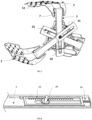
- An alternate locking mechanism could be a handle with a pin engaging a series of holes or slots in a plate as shown in Fig.9 .
- each arm 3 has an elongated hole 25.
- a series of rack teeth 33 are cut along one long side of the hole 25.
- the pinion 26 is driven by the rotation of handle 5, in this case connected by spring 22.
- the turning of the handle 5 will cause the assembly to rotate and the pinion 26 will then engage with the teeth to extend or retract the arms 3.
- Fig.8 there is shown such an alternative embodiment for keeping the anti-slip element 2 in contact with the tyre.
- arm 3 is formed as a hollow tube, wherein the rack 33 is a slideable element positioned inside arm 3.
- the outer surface of arm 3 is removed such that the inner mechanism is visible.
- spring 34 is arranged to bias the arm to its retracted position. When the arms are extended the spring 34 will exert a force that seeks to retract the arms 3 and thus hold the anti-slip element 2 in a tight position against the tyre.
- springs are internalised and do not increase the thickness of device 1.
- One or several springs 34 may be used if greater spring force is required than that provided by a single spring 34.
- a further variant of device 1 which utilizes the internal spring mechanism described here may be envisaged wherein anti-slip elements 2 are permanently affixed to arms 3 with no sliding relationship between them at attachment point 7. Instead, in this embodiment, the inwards compression resulting from the wheel driving over the anti-slip element 2 would be allowed for by the relative movement of rack 33 to arm 3.
- This has the advantage of simplifying the attachment of anti-slip components 2 to arms 3, but the disadvantages of a greater space requirement when stored and that the arms 3 will slide relative to each other within housing 6, which may result in more wear to these components.
- Fig.9 shows an embodiment of handle 5 and locking ring 23 alone for ease of understanding.
- ring 23 is penetrated with a plurality of holes 32.
- a pin 35 is used to lock the rotation of handle 5 relative to ring 23, whereby pin 35 connects removably with the nearest hole 32 to the desired locking position.
- the arms 3 slide linearly as described earlier, but are self-tightening with for example a one direction ratchet mechanism.
- a handle 5 would not be necessary, and instead a release mnchanism would be activated tn allow the arms 3 tn move outwards for removal from the wheel.
- the device When not in use the device is stored in the boot of the car. When it is needed the device will be placed beside the wheel and the handle first turned anti clockwise to extend the arms 3 outwards such that the device can be mounted onto the wheel. When in place around the tyre the handle 5 will be turned in the clockwise direction to retract the arms 3 until the anti-slip elements 2 fit tightly around the rim of the wheel. The same procedure is used to mount a second device on the other driving wheel. While it is not foreseen that it should be necessary to use the device on all four wheels of a 4 wheel drive car, it may at times be necessary since some 4-wheel drive cars will adjust the power to the driving axle that has the least resistance.
- FIG.10 shows two alternative embodiments of arrangements of spring elements in anti-slip components. Multiple springs 50, 51 at the extremities of arms 3 acting to pretension sleeves 10 and thus force anti-slip elements 2 inwards. A further embodiment utilises springs located internally within the arms 3. Such an embodiment is described in Fig.9 .
Landscapes
- Engineering & Computer Science (AREA)
- Mechanical Engineering (AREA)
- Tires In General (AREA)
- Braking Arrangements (AREA)
Claims (11)
- Gleitschutzvorrichtung (1) zum Verbessern einer Traktion auf rutschigen Straßen, umfassend:- 3 Arme (3), die von einer Nabe (4) radial vorstehen, die an der Außenseite eines Rads platziert werden und in Antirutschelementen (2) enden, die vorgesehen sind, um an der Laufflächenoberfläche des Reifens angeordnet zu werden,- Betätigungsmittel, die mit der Nabe (4) verbunden sind, um das Ausfahren oder Einziehen der Arme (3) zu ermöglichen,- wobei die Antirutschelemente (2) mit einer Schulter (13) ausgestattet sind, die angeordnet ist, um das Rad zu hintergreifen,- wobei die Betätigungsmittel mit Verriegelungsmitteln ausgestattet sind, die das Ausfahren der Arme (3) verhindern, wenn sie in Eingriff genommen sind,wobei die Arme (3) mit einem Druckgelenk (14) ausgestattet sind, das die nach innen gerichtete Verschiebung der Antirutschelemente (2) ermöglicht, um einer Verschiebung des Reifens zu folgen, ohne wiederum die Nabe (4) zu verschieben, dadurch gekennzeichnet, dassein Griff (5) der Betätigungsmittel mit der Nabe (4) rotierbar verbunden ist und durch Zahnräder (26) mit den Armen (3) derart verbunden ist, dass eine rotierende Hin- und Herbewegung des Griffs (5) in eine lineare Bewegung der Arme (3) umgesetzt wird,jeder Arm (3) ein längliches Loch (25) und eine Reihe von Zahnstangenzähnen (33) aufweist, die entlang einer langen Seite des Lochs (25) eingeschnitten sind, wo die Zahnräder ein Ritzel (26) umfassen, das angepasst ist, um durch die Rotation des Griffs (5) derart angetrieben zu werden, dass ein Drehen des Griffs (5) bewirken wird, dass das Ritzel (26) rotiert und die Zähne (33) in Eingriff nimmt, um die Arme (3) auszufahren oder einzufahren.
- Gleitschutzvorrichtung (1) nach Anspruch 1,
dadurch gekennzeichnet, dass die Vorrichtung (1) ein nach innen vorgespanntes Federelement (22,34, 50, 51) einschließt, wodurch Antirutschelemente (2) einen positiven, nach innen gerichteten Druck auf den Reifen beibehalten. - Gleitschutzvorrichtung (1) nach Anspruch 2,
dadurch gekennzeichnet, dass die Nabe (4) mit einem Federelement (22) ausgestattet ist. - Gleitschutzvorrichtung (1) nach Anspruch 2,
dadurch gekennzeichnet, dass die Arme (3) mit einem Federelement (34) ausgestattet sind. - Gleitschutzvorrichtung (1) nach Anspruch 2,
dadurch gekennzeichnet, dass die Antirutschelemente (2) mit einem Federelement (50,51) ausgestattet sind. - Gleitschutzvorrichtung (1) nach einem der vorstehenden Ansprüche,
dadurch gekennzeichnet, dass die Arme (3) durch Einstellen der Länge der Arme (3) an einer Auswahl von Raddurchmessern montiert werden können. - Gleitschutzvorrichtung (1) nach einem der vorstehenden Ansprüche,
dadurch gekennzeichnet, dass das Antirutschelement (2) ferner in 2 Hauptteile derart unterteilt ist, dass die Entfernung zwischen der Schulter (13) und dem Arm (3) einstellbar ist, um sich für unterschiedliche Reifenbreiten zu eignen. - Gleitschutzvorrichtung (1) nach einem der vorstehenden Ansprüche,
dadurch gekennzeichnet, dass das Antirutschelement (2) an seinen Innen- und Außenoberflächen mit mehreren unregelmäßig beabstandeten Erhebungen ausgestattet ist. - Gleitschutzvorrichtung (1) nach einem der Ansprüche 1 bis 5,
dadurch gekennzeichnet, dass das Antirutschelement (2) an seinen Innen- und Außenoberflächen mit mehreren unregelmäßig beabstandeten Durchbrüchen ausgestattet ist. - Gleitschutzvorrichtung (1) nach einem der Ansprüche 1 bis 7,
dadurch gekennzeichnet, dass Antirutschelemente (2) an den Armen (3) klappbar angebracht sind und sich für eine kompakte Lagerung zusammenfalten lassen. - Gleitschutzvorrichtung (1) nach einem der Ansprüche 1 bis 7,
dadurch gekennzeichnet, dass Antirutschelemente (2) für die kompakte Lagerung von den Armen (3) abnehmbar sind.
Applications Claiming Priority (2)
| Application Number | Priority Date | Filing Date | Title |
|---|---|---|---|
| NO20191262A NO345421B1 (en) | 2019-10-22 | 2019-10-22 | Anti-skid device |
| PCT/NO2020/050250 WO2021080435A1 (en) | 2019-10-22 | 2020-10-14 | Anti-skid device |
Publications (3)
| Publication Number | Publication Date |
|---|---|
| EP4048532A1 EP4048532A1 (de) | 2022-08-31 |
| EP4048532A4 EP4048532A4 (de) | 2023-12-06 |
| EP4048532B1 true EP4048532B1 (de) | 2024-12-18 |
Family
ID=74758394
Family Applications (1)
| Application Number | Title | Priority Date | Filing Date |
|---|---|---|---|
| EP20879766.2A Active EP4048532B1 (de) | 2019-10-22 | 2020-10-14 | Antirutschvorrichtung |
Country Status (7)
| Country | Link |
|---|---|
| US (1) | US12522032B2 (de) |
| EP (1) | EP4048532B1 (de) |
| CA (1) | CA3158340A1 (de) |
| FI (1) | FI4048532T3 (de) |
| NO (1) | NO345421B1 (de) |
| PL (1) | PL4048532T3 (de) |
| WO (1) | WO2021080435A1 (de) |
Families Citing this family (9)
| Publication number | Priority date | Publication date | Assignee | Title |
|---|---|---|---|---|
| NO345421B1 (en) | 2019-10-22 | 2021-01-25 | Hinor As | Anti-skid device |
| USD1033290S1 (en) * | 2020-11-05 | 2024-07-02 | Affin As | Grip device for a vehicle wheel |
| CN113199914B (zh) * | 2021-04-14 | 2023-05-26 | 滁州学院 | 一种便携式汽车陷坑脱困装置 |
| NO346418B1 (en) * | 2021-04-19 | 2022-07-18 | Affin As | Anti-skid device |
| CN113002250B (zh) * | 2021-05-06 | 2022-09-30 | 河北百龙汽车配件股份有限公司 | 一种隐藏式外胎防滑轮毂 |
| NO348115B1 (en) * | 2022-04-19 | 2024-08-19 | Affin As | Wheel clamps |
| NO20220526A1 (en) | 2022-05-08 | 2023-11-09 | Affin As | Anti-skid device |
| CN116252573B (zh) * | 2023-05-16 | 2023-08-29 | 之江实验室 | 一种车载防滑装置 |
| CN116533690B (zh) * | 2023-07-04 | 2023-09-08 | 之江实验室 | 一种用于车辆的自动防滑系统 |
Family Cites Families (38)
| Publication number | Priority date | Publication date | Assignee | Title |
|---|---|---|---|---|
| US2282470A (en) * | 1941-09-19 | 1942-05-12 | Archie E Gilbert | Nonskid attachment for vehicle wheels |
| US2454005A (en) | 1947-12-09 | 1948-11-16 | Earnest P Pletch | Traction increasing device for dual wheel vehicles |
| US2575263A (en) | 1950-03-14 | 1951-11-13 | Sr Harry J Eisenhauer | Antiskid device |
| US2873783A (en) * | 1954-12-06 | 1959-02-17 | O'higgins Michael | Anti-skid device for tires |
| US3016079A (en) * | 1960-01-08 | 1962-01-09 | Eli J Weller | Traction device |
| FR2297737A1 (fr) * | 1975-01-15 | 1976-08-13 | Meriaux Roger | Dispositif antiderapant amovible pour roue de vehicule |
| US4192367A (en) * | 1978-07-14 | 1980-03-11 | Ovila Chabot | Anti-skid wheel attachment device |
| US4209049A (en) | 1978-08-16 | 1980-06-24 | Alpine Industries, Inc. | Traction devices |
| IT7964813A0 (it) | 1979-11-26 | 1979-11-26 | Ricciardi Vittorio | Attrezzo meccanico antineve per veicoli di qualsiasi tipo a sistema universale |
| EP0056130B1 (de) | 1981-01-08 | 1985-06-05 | Niveau AG | Gleitschutzvorrichtung für bereifte, insbesondere luftbereifte Fahrzeugräder für Eis- und Schneeflächen |
| IT1226265B (it) * | 1982-11-12 | 1990-12-27 | Sunfilter Di Finelli Giuseppe | Struttura conponibile antislittamento per ruote di autoveicoli |
| IT8305115A0 (it) | 1983-02-08 | 1983-02-08 | Moniga Del Garda Brescia A | Dispositivo anti-slittamento per ruote di autoveicoli in genere. |
| FR2589796B1 (fr) | 1985-07-18 | 1988-02-12 | Cizaire Ivan | Dispositif antiderapant amovible pour roues a pneumatique de vehicules |
| JPS6478955A (en) | 1987-09-18 | 1989-03-24 | Aisin Seiki | Restraining device for car |
| US4834158A (en) | 1988-01-05 | 1989-05-30 | Danny Katz | Tire traction system |
| GB9223095D0 (en) * | 1992-11-04 | 1992-12-16 | Bennett Ernest F | Anti-slip device for vehicle wheels |
| HU218544B (hu) * | 1996-10-02 | 2000-10-28 | Keményföldi András | Kengyelszerkezet járműkerekek gumiabroncsaira időszakosan felszerelhető hókengyelekhez |
| US5735980A (en) * | 1996-12-16 | 1998-04-07 | Robeson; Palmer Edward | Traction device for a wheeled vehicle |
| US6053227A (en) | 1999-03-01 | 2000-04-25 | Robeson; Palmer Edward | Traction device for a wheeled vehicle |
| KR20040091223A (ko) * | 2003-04-19 | 2004-10-28 | 제갈준호 | 스노우 체인장치 |
| US6983778B1 (en) | 2003-10-09 | 2006-01-10 | Pitts Freddie L | Road gripping assembly |
| DE202004004887U1 (de) | 2004-03-23 | 2004-10-07 | Mast, Andrea, Dipl.-Kfm. | Vorrichtung zur Demobilisation von Fahrzeugen |
| US7426949B2 (en) * | 2005-11-23 | 2008-09-23 | Chaisson Jr Sidney J | Tool-free tire traction device |
| EP2050590B1 (de) | 2007-10-15 | 2013-05-22 | Thule S.p.A. | Von außen montierte Schneeketten mit einer Vorrichtung zu ihrer Befestigung am Rad |
| US20100170603A1 (en) * | 2008-04-29 | 2010-07-08 | Polyakovics Frank L | Easily mountable and removable universally adjustable traction apparatus for vehicle tires |
| US8113252B2 (en) * | 2009-10-23 | 2012-02-14 | London Reil | Tire traction device with guided radial tensioning arms |
| KR101334296B1 (ko) * | 2013-07-25 | 2013-12-09 | 주식회사 오토복스코리아 | 타이어 미끄럼 방지장치 |
| US9487056B1 (en) * | 2013-10-18 | 2016-11-08 | Nicholas Dolios | Motor vehicle tire traction device for ice and snow |
| US10328757B1 (en) | 2016-04-05 | 2019-06-25 | Robert Edward Goodson | Chain apparatus for use with a vehicular tire to enhance traction on slippery terrain |
| US10807423B2 (en) | 2017-01-06 | 2020-10-20 | Joseph Morgese | Ice and snow cleats for automobile and truck tires |
| CZ307348B6 (cs) * | 2017-02-07 | 2018-06-20 | Ing. Petr Gross S.R.O. | Protiskluzové zařízení pro automobilová kola |
| CN209757048U (zh) | 2018-12-30 | 2019-12-10 | 长春格瑞科技有限公司 | 一种车轮锁 |
| CN209904464U (zh) | 2019-04-10 | 2020-01-07 | 王萌 | 环抱式轮胎防滑装置 |
| NO345421B1 (en) | 2019-10-22 | 2021-01-25 | Hinor As | Anti-skid device |
| US12109854B2 (en) | 2019-12-16 | 2024-10-08 | Jeffrey S. Melcher | Tire bar and method of using the tire bar to unstick a vehicle |
| USD1033290S1 (en) | 2020-11-05 | 2024-07-02 | Affin As | Grip device for a vehicle wheel |
| NO346418B1 (en) | 2021-04-19 | 2022-07-18 | Affin As | Anti-skid device |
| NO20220526A1 (en) | 2022-05-08 | 2023-11-09 | Affin As | Anti-skid device |
-
2019
- 2019-10-22 NO NO20191262A patent/NO345421B1/en unknown
-
2020
- 2020-10-14 US US17/770,080 patent/US12522032B2/en active Active
- 2020-10-14 CA CA3158340A patent/CA3158340A1/en active Pending
- 2020-10-14 PL PL20879766.2T patent/PL4048532T3/pl unknown
- 2020-10-14 EP EP20879766.2A patent/EP4048532B1/de active Active
- 2020-10-14 WO PCT/NO2020/050250 patent/WO2021080435A1/en not_active Ceased
- 2020-10-14 FI FIEP20879766.2T patent/FI4048532T3/fi active
Also Published As
| Publication number | Publication date |
|---|---|
| EP4048532A4 (de) | 2023-12-06 |
| PL4048532T3 (pl) | 2025-05-05 |
| FI4048532T3 (fi) | 2025-03-24 |
| US12522032B2 (en) | 2026-01-13 |
| US20220410643A1 (en) | 2022-12-29 |
| NO345421B1 (en) | 2021-01-25 |
| WO2021080435A1 (en) | 2021-04-29 |
| NO20191262A1 (de) | 2021-01-25 |
| EP4048532A1 (de) | 2022-08-31 |
| CA3158340A1 (en) | 2021-04-29 |
Similar Documents
| Publication | Publication Date | Title |
|---|---|---|
| EP4048532B1 (de) | Antirutschvorrichtung | |
| US9981511B2 (en) | Tire traction devices | |
| US20100252160A1 (en) | Wheel hub connection-free tire traction device | |
| US5540267A (en) | Traction device for wheeled vehicles | |
| CN110494299A (zh) | 用于车轮的附接件 | |
| JP5919283B2 (ja) | 車輪を備えた車両のスリップを防止する装置 | |
| US11059335B2 (en) | Tire traction devices | |
| US11938763B2 (en) | Anti-skid device | |
| US4387930A (en) | Vehicle traction device | |
| US20250282188A1 (en) | Anti-skid device | |
| US5735980A (en) | Traction device for a wheeled vehicle | |
| CA2818590C (en) | Device for increasing tire friction and method of using the same | |
| US4872496A (en) | Readily installed tire cleats with improved fastening means | |
| CN108528154A (zh) | 一种防松脱的车轮防滑链 | |
| US6062348A (en) | Rapidly-deployable vehicle snow chain system having individually-replaceable interlocking chain attachment plates | |
| KR19990045978A (ko) | 미끄럼방지부재가내장된차량용휠 | |
| US1608431A (en) | Nonskid device | |
| CA1275232C (en) | Readily installed cleats for tire traction improvement |
Legal Events
| Date | Code | Title | Description |
|---|---|---|---|
| STAA | Information on the status of an ep patent application or granted ep patent |
Free format text: STATUS: THE INTERNATIONAL PUBLICATION HAS BEEN MADE |
|
| PUAI | Public reference made under article 153(3) epc to a published international application that has entered the european phase |
Free format text: ORIGINAL CODE: 0009012 |
|
| STAA | Information on the status of an ep patent application or granted ep patent |
Free format text: STATUS: REQUEST FOR EXAMINATION WAS MADE |
|
| 17P | Request for examination filed |
Effective date: 20220503 |
|
| AK | Designated contracting states |
Kind code of ref document: A1 Designated state(s): AL AT BE BG CH CY CZ DE DK EE ES FI FR GB GR HR HU IE IS IT LI LT LU LV MC MK MT NL NO PL PT RO RS SE SI SK SM TR |
|
| DAV | Request for validation of the european patent (deleted) | ||
| DAX | Request for extension of the european patent (deleted) | ||
| A4 | Supplementary search report drawn up and despatched |
Effective date: 20231107 |
|
| RIC1 | Information provided on ipc code assigned before grant |
Ipc: B60C 27/04 20060101ALI20231031BHEP Ipc: B60C 27/02 20060101AFI20231031BHEP |
|
| GRAP | Despatch of communication of intention to grant a patent |
Free format text: ORIGINAL CODE: EPIDOSNIGR1 |
|
| STAA | Information on the status of an ep patent application or granted ep patent |
Free format text: STATUS: GRANT OF PATENT IS INTENDED |
|
| INTG | Intention to grant announced |
Effective date: 20240715 |
|
| GRAS | Grant fee paid |
Free format text: ORIGINAL CODE: EPIDOSNIGR3 |
|
| GRAA | (expected) grant |
Free format text: ORIGINAL CODE: 0009210 |
|
| STAA | Information on the status of an ep patent application or granted ep patent |
Free format text: STATUS: THE PATENT HAS BEEN GRANTED |
|
| AK | Designated contracting states |
Kind code of ref document: B1 Designated state(s): AL AT BE BG CH CY CZ DE DK EE ES FI FR GB GR HR HU IE IS IT LI LT LU LV MC MK MT NL NO PL PT RO RS SE SI SK SM TR |
|
| REG | Reference to a national code |
Ref country code: CH Ref legal event code: EP |
|
| REG | Reference to a national code |
Ref country code: DE Ref legal event code: R096 Ref document number: 602020043517 Country of ref document: DE |
|
| REG | Reference to a national code |
Ref country code: IE Ref legal event code: FG4D |
|
| REG | Reference to a national code |
Ref country code: FI Ref legal event code: FGE |
|
| REG | Reference to a national code |
Ref country code: SE Ref legal event code: TRGR |
|
| REG | Reference to a national code |
Ref country code: LT Ref legal event code: MG9D |
|
| PG25 | Lapsed in a contracting state [announced via postgrant information from national office to epo] |
Ref country code: HR Free format text: LAPSE BECAUSE OF FAILURE TO SUBMIT A TRANSLATION OF THE DESCRIPTION OR TO PAY THE FEE WITHIN THE PRESCRIBED TIME-LIMIT Effective date: 20241218 |
|
| PG25 | Lapsed in a contracting state [announced via postgrant information from national office to epo] |
Ref country code: BG Free format text: LAPSE BECAUSE OF FAILURE TO SUBMIT A TRANSLATION OF THE DESCRIPTION OR TO PAY THE FEE WITHIN THE PRESCRIBED TIME-LIMIT Effective date: 20241218 |
|
| PG25 | Lapsed in a contracting state [announced via postgrant information from national office to epo] |
Ref country code: NO Free format text: LAPSE BECAUSE OF FAILURE TO SUBMIT A TRANSLATION OF THE DESCRIPTION OR TO PAY THE FEE WITHIN THE PRESCRIBED TIME-LIMIT Effective date: 20250318 |
|
| REG | Reference to a national code |
Ref country code: NL Ref legal event code: MP Effective date: 20241218 |
|
| PG25 | Lapsed in a contracting state [announced via postgrant information from national office to epo] |
Ref country code: GR Free format text: LAPSE BECAUSE OF FAILURE TO SUBMIT A TRANSLATION OF THE DESCRIPTION OR TO PAY THE FEE WITHIN THE PRESCRIBED TIME-LIMIT Effective date: 20250319 Ref country code: LV Free format text: LAPSE BECAUSE OF FAILURE TO SUBMIT A TRANSLATION OF THE DESCRIPTION OR TO PAY THE FEE WITHIN THE PRESCRIBED TIME-LIMIT Effective date: 20241218 |
|
| PG25 | Lapsed in a contracting state [announced via postgrant information from national office to epo] |
Ref country code: RS Free format text: LAPSE BECAUSE OF FAILURE TO SUBMIT A TRANSLATION OF THE DESCRIPTION OR TO PAY THE FEE WITHIN THE PRESCRIBED TIME-LIMIT Effective date: 20250318 |
|
| PG25 | Lapsed in a contracting state [announced via postgrant information from national office to epo] |
Ref country code: NL Free format text: LAPSE BECAUSE OF FAILURE TO SUBMIT A TRANSLATION OF THE DESCRIPTION OR TO PAY THE FEE WITHIN THE PRESCRIBED TIME-LIMIT Effective date: 20241218 |
|
| PG25 | Lapsed in a contracting state [announced via postgrant information from national office to epo] |
Ref country code: SM Free format text: LAPSE BECAUSE OF FAILURE TO SUBMIT A TRANSLATION OF THE DESCRIPTION OR TO PAY THE FEE WITHIN THE PRESCRIBED TIME-LIMIT Effective date: 20241218 |
|
| PGFP | Annual fee paid to national office [announced via postgrant information from national office to epo] |
Ref country code: PL Payment date: 20250425 Year of fee payment: 6 |
|
| PG25 | Lapsed in a contracting state [announced via postgrant information from national office to epo] |
Ref country code: ES Free format text: LAPSE BECAUSE OF FAILURE TO SUBMIT A TRANSLATION OF THE DESCRIPTION OR TO PAY THE FEE WITHIN THE PRESCRIBED TIME-LIMIT Effective date: 20241218 |
|
| PG25 | Lapsed in a contracting state [announced via postgrant information from national office to epo] |
Ref country code: IS Free format text: LAPSE BECAUSE OF FAILURE TO SUBMIT A TRANSLATION OF THE DESCRIPTION OR TO PAY THE FEE WITHIN THE PRESCRIBED TIME-LIMIT Effective date: 20250418 |
|
| PG25 | Lapsed in a contracting state [announced via postgrant information from national office to epo] |
Ref country code: PT Free format text: LAPSE BECAUSE OF FAILURE TO SUBMIT A TRANSLATION OF THE DESCRIPTION OR TO PAY THE FEE WITHIN THE PRESCRIBED TIME-LIMIT Effective date: 20250421 |
|
| PG25 | Lapsed in a contracting state [announced via postgrant information from national office to epo] |
Ref country code: EE Free format text: LAPSE BECAUSE OF FAILURE TO SUBMIT A TRANSLATION OF THE DESCRIPTION OR TO PAY THE FEE WITHIN THE PRESCRIBED TIME-LIMIT Effective date: 20241218 |
|
| PG25 | Lapsed in a contracting state [announced via postgrant information from national office to epo] |
Ref country code: RO Free format text: LAPSE BECAUSE OF FAILURE TO SUBMIT A TRANSLATION OF THE DESCRIPTION OR TO PAY THE FEE WITHIN THE PRESCRIBED TIME-LIMIT Effective date: 20241218 |
|
| PG25 | Lapsed in a contracting state [announced via postgrant information from national office to epo] |
Ref country code: SK Free format text: LAPSE BECAUSE OF FAILURE TO SUBMIT A TRANSLATION OF THE DESCRIPTION OR TO PAY THE FEE WITHIN THE PRESCRIBED TIME-LIMIT Effective date: 20241218 |
|
| PG25 | Lapsed in a contracting state [announced via postgrant information from national office to epo] |
Ref country code: CZ Free format text: LAPSE BECAUSE OF FAILURE TO SUBMIT A TRANSLATION OF THE DESCRIPTION OR TO PAY THE FEE WITHIN THE PRESCRIBED TIME-LIMIT Effective date: 20241218 |
|
| PG25 | Lapsed in a contracting state [announced via postgrant information from national office to epo] |
Ref country code: IT Free format text: LAPSE BECAUSE OF FAILURE TO SUBMIT A TRANSLATION OF THE DESCRIPTION OR TO PAY THE FEE WITHIN THE PRESCRIBED TIME-LIMIT Effective date: 20241218 |
|
| REG | Reference to a national code |
Ref country code: DE Ref legal event code: R097 Ref document number: 602020043517 Country of ref document: DE |
|
| PG25 | Lapsed in a contracting state [announced via postgrant information from national office to epo] |
Ref country code: DK Free format text: LAPSE BECAUSE OF FAILURE TO SUBMIT A TRANSLATION OF THE DESCRIPTION OR TO PAY THE FEE WITHIN THE PRESCRIBED TIME-LIMIT Effective date: 20241218 |
|
| PGFP | Annual fee paid to national office [announced via postgrant information from national office to epo] |
Ref country code: TR Payment date: 20250702 Year of fee payment: 6 |
|
| PLBE | No opposition filed within time limit |
Free format text: ORIGINAL CODE: 0009261 |
|
| STAA | Information on the status of an ep patent application or granted ep patent |
Free format text: STATUS: NO OPPOSITION FILED WITHIN TIME LIMIT |
|
| REG | Reference to a national code |
Ref country code: CH Ref legal event code: L10 Free format text: ST27 STATUS EVENT CODE: U-0-0-L10-L00 (AS PROVIDED BY THE NATIONAL OFFICE) Effective date: 20251029 |
|
| REG | Reference to a national code |
Ref country code: CH Ref legal event code: U11 Free format text: ST27 STATUS EVENT CODE: U-0-0-U10-U11 (AS PROVIDED BY THE NATIONAL OFFICE) Effective date: 20251101 |
|
| 26N | No opposition filed |
Effective date: 20250919 |
|
| PGFP | Annual fee paid to national office [announced via postgrant information from national office to epo] |
Ref country code: DE Payment date: 20251022 Year of fee payment: 6 |
|
| PGFP | Annual fee paid to national office [announced via postgrant information from national office to epo] |
Ref country code: AT Payment date: 20251029 Year of fee payment: 6 |
|
| PGFP | Annual fee paid to national office [announced via postgrant information from national office to epo] |
Ref country code: FI Payment date: 20251027 Year of fee payment: 6 |
|
| PGFP | Annual fee paid to national office [announced via postgrant information from national office to epo] |
Ref country code: SE Payment date: 20251023 Year of fee payment: 6 Ref country code: CH Payment date: 20251101 Year of fee payment: 6 |