EP4046881A1 - Mécanisme de support - Google Patents
Mécanisme de support Download PDFInfo
- Publication number
- EP4046881A1 EP4046881A1 EP22156437.0A EP22156437A EP4046881A1 EP 4046881 A1 EP4046881 A1 EP 4046881A1 EP 22156437 A EP22156437 A EP 22156437A EP 4046881 A1 EP4046881 A1 EP 4046881A1
- Authority
- EP
- European Patent Office
- Prior art keywords
- carrying
- battery
- arm
- strap
- belt
- Prior art date
- Legal status (The legal status is an assumption and is not a legal conclusion. Google has not performed a legal analysis and makes no representation as to the accuracy of the status listed.)
- Granted
Links
Images


Classifications
-
- B—PERFORMING OPERATIONS; TRANSPORTING
- B62—LAND VEHICLES FOR TRAVELLING OTHERWISE THAN ON RAILS
- B62J—CYCLE SADDLES OR SEATS; AUXILIARY DEVICES OR ACCESSORIES SPECIALLY ADAPTED TO CYCLES AND NOT OTHERWISE PROVIDED FOR, e.g. ARTICLE CARRIERS OR CYCLE PROTECTORS
- B62J43/00—Arrangements of batteries
- B62J43/10—Arrangements of batteries for propulsion
- B62J43/16—Arrangements of batteries for propulsion on motorcycles or the like
-
- B—PERFORMING OPERATIONS; TRANSPORTING
- B60—VEHICLES IN GENERAL
- B60L—PROPULSION OF ELECTRICALLY-PROPELLED VEHICLES; SUPPLYING ELECTRIC POWER FOR AUXILIARY EQUIPMENT OF ELECTRICALLY-PROPELLED VEHICLES; ELECTRODYNAMIC BRAKE SYSTEMS FOR VEHICLES IN GENERAL; MAGNETIC SUSPENSION OR LEVITATION FOR VEHICLES; MONITORING OPERATING VARIABLES OF ELECTRICALLY-PROPELLED VEHICLES; ELECTRIC SAFETY DEVICES FOR ELECTRICALLY-PROPELLED VEHICLES
- B60L53/00—Methods of charging batteries, specially adapted for electric vehicles; Charging stations or on-board charging equipment therefor; Exchange of energy storage elements in electric vehicles
- B60L53/30—Constructional details of charging stations
-
- B—PERFORMING OPERATIONS; TRANSPORTING
- B60—VEHICLES IN GENERAL
- B60L—PROPULSION OF ELECTRICALLY-PROPELLED VEHICLES; SUPPLYING ELECTRIC POWER FOR AUXILIARY EQUIPMENT OF ELECTRICALLY-PROPELLED VEHICLES; ELECTRODYNAMIC BRAKE SYSTEMS FOR VEHICLES IN GENERAL; MAGNETIC SUSPENSION OR LEVITATION FOR VEHICLES; MONITORING OPERATING VARIABLES OF ELECTRICALLY-PROPELLED VEHICLES; ELECTRIC SAFETY DEVICES FOR ELECTRICALLY-PROPELLED VEHICLES
- B60L53/00—Methods of charging batteries, specially adapted for electric vehicles; Charging stations or on-board charging equipment therefor; Exchange of energy storage elements in electric vehicles
- B60L53/80—Exchanging energy storage elements, e.g. removable batteries
-
- B—PERFORMING OPERATIONS; TRANSPORTING
- B62—LAND VEHICLES FOR TRAVELLING OTHERWISE THAN ON RAILS
- B62B—HAND-PROPELLED VEHICLES, e.g. HAND CARTS OR PERAMBULATORS; SLEDGES
- B62B3/00—Hand carts having more than one axis carrying transport wheels; Steering devices therefor; Equipment therefor
- B62B3/04—Hand carts having more than one axis carrying transport wheels; Steering devices therefor; Equipment therefor involving means for grappling or securing in place objects to be carried; Loading or unloading equipment
- B62B3/06—Hand carts having more than one axis carrying transport wheels; Steering devices therefor; Equipment therefor involving means for grappling or securing in place objects to be carried; Loading or unloading equipment for simply clearing the load from the ground
- B62B3/0606—Hand carts having more than one axis carrying transport wheels; Steering devices therefor; Equipment therefor involving means for grappling or securing in place objects to be carried; Loading or unloading equipment for simply clearing the load from the ground manually operated
-
- B—PERFORMING OPERATIONS; TRANSPORTING
- B62—LAND VEHICLES FOR TRAVELLING OTHERWISE THAN ON RAILS
- B62B—HAND-PROPELLED VEHICLES, e.g. HAND CARTS OR PERAMBULATORS; SLEDGES
- B62B3/00—Hand carts having more than one axis carrying transport wheels; Steering devices therefor; Equipment therefor
- B62B3/04—Hand carts having more than one axis carrying transport wheels; Steering devices therefor; Equipment therefor involving means for grappling or securing in place objects to be carried; Loading or unloading equipment
- B62B3/06—Hand carts having more than one axis carrying transport wheels; Steering devices therefor; Equipment therefor involving means for grappling or securing in place objects to be carried; Loading or unloading equipment for simply clearing the load from the ground
- B62B3/0643—Hand carts having more than one axis carrying transport wheels; Steering devices therefor; Equipment therefor involving means for grappling or securing in place objects to be carried; Loading or unloading equipment for simply clearing the load from the ground the wheels remaining stationary while the supporting surface is lifted
-
- B—PERFORMING OPERATIONS; TRANSPORTING
- B62—LAND VEHICLES FOR TRAVELLING OTHERWISE THAN ON RAILS
- B62B—HAND-PROPELLED VEHICLES, e.g. HAND CARTS OR PERAMBULATORS; SLEDGES
- B62B3/00—Hand carts having more than one axis carrying transport wheels; Steering devices therefor; Equipment therefor
- B62B3/10—Hand carts having more than one axis carrying transport wheels; Steering devices therefor; Equipment therefor characterised by supports specially adapted to objects of definite shape
- B62B3/106—Hand carts having more than one axis carrying transport wheels; Steering devices therefor; Equipment therefor characterised by supports specially adapted to objects of definite shape the objects being bags
-
- B—PERFORMING OPERATIONS; TRANSPORTING
- B62—LAND VEHICLES FOR TRAVELLING OTHERWISE THAN ON RAILS
- B62J—CYCLE SADDLES OR SEATS; AUXILIARY DEVICES OR ACCESSORIES SPECIALLY ADAPTED TO CYCLES AND NOT OTHERWISE PROVIDED FOR, e.g. ARTICLE CARRIERS OR CYCLE PROTECTORS
- B62J43/00—Arrangements of batteries
- B62J43/20—Arrangements of batteries characterised by the mounting
- B62J43/23—Arrangements of batteries characterised by the mounting dismounted when charging
-
- B—PERFORMING OPERATIONS; TRANSPORTING
- B66—HOISTING; LIFTING; HAULING
- B66C—CRANES; LOAD-ENGAGING ELEMENTS OR DEVICES FOR CRANES, CAPSTANS, WINCHES, OR TACKLES
- B66C1/00—Load-engaging elements or devices attached to lifting or lowering gear of cranes or adapted for connection therewith for transmitting lifting forces to articles or groups of articles
- B66C1/10—Load-engaging elements or devices attached to lifting or lowering gear of cranes or adapted for connection therewith for transmitting lifting forces to articles or groups of articles by mechanical means
- B66C1/12—Slings comprising chains, wires, ropes, or bands; Nets
- B66C1/127—Nets
-
- B—PERFORMING OPERATIONS; TRANSPORTING
- B66—HOISTING; LIFTING; HAULING
- B66F—HOISTING, LIFTING, HAULING OR PUSHING, NOT OTHERWISE PROVIDED FOR, e.g. DEVICES WHICH APPLY A LIFTING OR PUSHING FORCE DIRECTLY TO THE SURFACE OF A LOAD
- B66F9/00—Devices for lifting or lowering bulky or heavy goods for loading or unloading purposes
- B66F9/06—Devices for lifting or lowering bulky or heavy goods for loading or unloading purposes movable, with their loads, on wheels or the like, e.g. fork-lift trucks
- B66F9/075—Constructional features or details
- B66F9/07513—Details concerning the chassis
- B66F9/0754—Battery removal arrangements
-
- B—PERFORMING OPERATIONS; TRANSPORTING
- B60—VEHICLES IN GENERAL
- B60K—ARRANGEMENT OR MOUNTING OF PROPULSION UNITS OR OF TRANSMISSIONS IN VEHICLES; ARRANGEMENT OR MOUNTING OF PLURAL DIVERSE PRIME-MOVERS IN VEHICLES; AUXILIARY DRIVES FOR VEHICLES; INSTRUMENTATION OR DASHBOARDS FOR VEHICLES; ARRANGEMENTS IN CONNECTION WITH COOLING, AIR INTAKE, GAS EXHAUST OR FUEL SUPPLY OF PROPULSION UNITS IN VEHICLES
- B60K1/00—Arrangement or mounting of electrical propulsion units
- B60K1/04—Arrangement or mounting of electrical propulsion units of the electric storage means for propulsion
- B60K2001/0455—Removal or replacement of the energy storages
- B60K2001/0466—Removal or replacement of the energy storages from above
-
- B—PERFORMING OPERATIONS; TRANSPORTING
- B60—VEHICLES IN GENERAL
- B60Y—INDEXING SCHEME RELATING TO ASPECTS CROSS-CUTTING VEHICLE TECHNOLOGY
- B60Y2200/00—Type of vehicle
- B60Y2200/10—Road Vehicles
- B60Y2200/12—Motorcycles, Trikes; Quads; Scooters
- B60Y2200/126—Scooters
-
- B—PERFORMING OPERATIONS; TRANSPORTING
- B62—LAND VEHICLES FOR TRAVELLING OTHERWISE THAN ON RAILS
- B62B—HAND-PROPELLED VEHICLES, e.g. HAND CARTS OR PERAMBULATORS; SLEDGES
- B62B2202/00—Indexing codes relating to type or characteristics of transported articles
- B62B2202/61—Batteries
-
- B—PERFORMING OPERATIONS; TRANSPORTING
- B62—LAND VEHICLES FOR TRAVELLING OTHERWISE THAN ON RAILS
- B62B—HAND-PROPELLED VEHICLES, e.g. HAND CARTS OR PERAMBULATORS; SLEDGES
- B62B2203/00—Grasping, holding, supporting the objects
- B62B2203/10—Grasping, holding, supporting the objects comprising lifting means
- B62B2203/11—Grasping, holding, supporting the objects comprising lifting means comprising a crane
-
- B—PERFORMING OPERATIONS; TRANSPORTING
- B62—LAND VEHICLES FOR TRAVELLING OTHERWISE THAN ON RAILS
- B62K—CYCLES; CYCLE FRAMES; CYCLE STEERING DEVICES; RIDER-OPERATED TERMINAL CONTROLS SPECIALLY ADAPTED FOR CYCLES; CYCLE AXLE SUSPENSIONS; CYCLE SIDECARS, FORECARS, OR THE LIKE
- B62K2202/00—Motorised scooters
-
- B—PERFORMING OPERATIONS; TRANSPORTING
- B62—LAND VEHICLES FOR TRAVELLING OTHERWISE THAN ON RAILS
- B62K—CYCLES; CYCLE FRAMES; CYCLE STEERING DEVICES; RIDER-OPERATED TERMINAL CONTROLS SPECIALLY ADAPTED FOR CYCLES; CYCLE AXLE SUSPENSIONS; CYCLE SIDECARS, FORECARS, OR THE LIKE
- B62K2204/00—Adaptations for driving cycles by electric motor
-
- H—ELECTRICITY
- H01—ELECTRIC ELEMENTS
- H01M—PROCESSES OR MEANS, e.g. BATTERIES, FOR THE DIRECT CONVERSION OF CHEMICAL ENERGY INTO ELECTRICAL ENERGY
- H01M50/00—Constructional details or processes of manufacture of the non-active parts of electrochemical cells other than fuel cells, e.g. hybrid cells
- H01M50/20—Mountings; Secondary casings or frames; Racks, modules or packs; Suspension devices; Shock absorbers; Transport or carrying devices; Holders
- H01M50/256—Carrying devices, e.g. belts
-
- Y—GENERAL TAGGING OF NEW TECHNOLOGICAL DEVELOPMENTS; GENERAL TAGGING OF CROSS-SECTIONAL TECHNOLOGIES SPANNING OVER SEVERAL SECTIONS OF THE IPC; TECHNICAL SUBJECTS COVERED BY FORMER USPC CROSS-REFERENCE ART COLLECTIONS [XRACs] AND DIGESTS
- Y02—TECHNOLOGIES OR APPLICATIONS FOR MITIGATION OR ADAPTATION AGAINST CLIMATE CHANGE
- Y02T—CLIMATE CHANGE MITIGATION TECHNOLOGIES RELATED TO TRANSPORTATION
- Y02T10/00—Road transport of goods or passengers
- Y02T10/60—Other road transportation technologies with climate change mitigation effect
- Y02T10/70—Energy storage systems for electromobility, e.g. batteries
-
- Y—GENERAL TAGGING OF NEW TECHNOLOGICAL DEVELOPMENTS; GENERAL TAGGING OF CROSS-SECTIONAL TECHNOLOGIES SPANNING OVER SEVERAL SECTIONS OF THE IPC; TECHNICAL SUBJECTS COVERED BY FORMER USPC CROSS-REFERENCE ART COLLECTIONS [XRACs] AND DIGESTS
- Y02—TECHNOLOGIES OR APPLICATIONS FOR MITIGATION OR ADAPTATION AGAINST CLIMATE CHANGE
- Y02T—CLIMATE CHANGE MITIGATION TECHNOLOGIES RELATED TO TRANSPORTATION
- Y02T10/00—Road transport of goods or passengers
- Y02T10/60—Other road transportation technologies with climate change mitigation effect
- Y02T10/7072—Electromobility specific charging systems or methods for batteries, ultracapacitors, supercapacitors or double-layer capacitors
Definitions
- the present invention relates to a carrying mechanism used, during replacement of batteries used in vehicles, to carry the battery or place it in a preferred position in the vehicle.
- the battery which does not have a weight suitable for being carried ergonomically by people and poses a danger in case of falling, must be safely removed/installed. Batteries are generally used in vehicles. In case of need for technical service or replacing the battery of vehicles such as motorcycles, the battery needs to be removed and installed.
- the carrying of batteries can be ensured by using human force.
- the said batteries have a weight in the range of 10-40 kg.
- occupational accidents may occur during the carrying and placement of the battery. If the battery, which contains hazardous chemicals and is classified as dangerous, is carried and placed by human force, fire may occur as a result of damage to the battery. In case the battery is carried or placed by human force, or if the battery falls, it may be the case that the employee is exposed to chemicals that will significantly affect his health.
- the maximum weight that a field worker can carry without support is 10 kg. Auxiliary equipment is required for weights above this.
- the battery installation, removal and replacement to/from the vehicle creates a big problem. In this case, there is a need for a carrying mechanism that ensures the carrying, lifting and placement of the said battery without using human power.
- a battery carrying trolley is described in the Chinese utility model document numbered CN210258092 (U) and dated 09.05.2019 .
- the carrying trolley with wheels has a handle and there is a counterweight thereon.
- the carrying and holding function of the battery is provided by the handle system.
- the battery is held by adjusting the distance with the movable arm and the fixed arm.
- the height adjustment of the apparatus is provided by a mechanism with a lever jack logic, using an engine.
- a mechanism is found with wheels and having a lever jack for height adjustment thereon.
- the battery can be carried by being compressed by two handles.
- a conveyor belt is passed around the battery and the said belt has two carrying arms.
- the two arms of the belt are passed to the carrying profile of the carrying trolley and the lifting profile to which the carrying profile is attached is moved on the vertical axis by working with the logic of a lever jack.
- the carrying mechanism of the invention ensures the battery to be carried by working like a lever jack.
- carrying straps are fixed on the battery pack. At the top of these belts, there are holes for the carrying equipment to pass through.
- Velcro straps are fixed on the bottom of the battery so that these carrying straps at the top of the battery do not sit idle.
- the corresponding parts of these straps are fixed on the battery cover. In this way, it is fixed on the cover when not in use.
- the wheel area of the carrying stand is brought closer to the battery so that it passes under the vehicle.
- the battery carrying profile is passed through the battery carrying strap holes and the safety pin is attached.
- the object of the present invention is to realize a carrying mechanism that enables the battery to be carried or lifted without the use of human power.
- Another object of the present invention is to realize a carrying mechanism that enables the battery to be placed by being immobile on the horizontal axis and being raised and lowered on the vertical axis.
- Another object of the present invention is to realize a carrying mechanism that prevents the battery from being damaged during carriage by ensuring the battery to be carried in a balanced manner without the need for human power.
- Another object of the present invention is to realize a carrying mechanism that enables the battery to be moved up and down on the vertical axis by means of the hanger-jack mechanism.
- Another object of the present invention is to realize a carrying mechanism that ensures the protection of employee health by unmanned carrying of the battery.
- a carrying mechanism which is defined in the first claim and other claims dependent on this claim, realized in order to achieve the aim of the present invention, consists of a carrying strap and a carrier.
- the battery is first placed in the carrying strap.
- the battery is placed in the insertion clearance in the carrying strap.
- the containment belt wraps around the battery.
- the carrying belt remains at the end of the battery.
- the carrying belt can be fixed to the upper part of the battery with the strap stabilizer located at the belt tip of the carrying belt.
- the carrying belt is extended over the two parallel sides of the battery.
- the battery which is placed in the carrying strap, is passed from the carrying belt to the carrying arm of the carrier when it is preferred to be carried to the vehicle.
- the battery is passed from the support slot of the carrying belt to the carrying arm.
- the carrying arm comes into contact with the carrying support in the support slot.
- it is passed from the carrying strap found on the battery to the carrying arm with the carrying belt, it remains balanced.
- a blocking pin is inserted into the blocking gap to prevent the battery from being separated from the carrying strap together with the carrying strap.
- the subject of the application allows the battery to be lifted on the vertical axis according to the size of the vehicle in which the carrier battery will be placed.
- the lifting profile which is connected to the carrying arm, is opened upwards on the vertical axis by means of the motion provider.
- the second movable arm is in the first movable arm and the first movable arm is nested within the fixed arm.
- the motion provider is rotated by the user about its central axis in one direction, the first movable arm moves in the vertical axis upwards within the fixed arm.
- the second movable arm moves upwards in the vertical axis within the first movable arm, as the motion provider is rotated in one direction around its central axis by the user.
- the plane to be placed is adjusted according to the size of the vehicle in which the battery will be placed, by rotating the motion provider in one direction or the other around its central axis by the user.
- the carrier is brought closer to the vehicle by means of the carrying wheels on the carrying feet by applying force thereon. After the carrier is brought closer to the vehicle by means of the carrying wheels on the carrying leg, the position where the battery will be placed is selected and the motion provider is used again.
- the first movable arm moves in the vertical axis downwards within the fixed arm by rotating the motion provider in another direction around its central axis.
- the second movable arm moves into the first movable arm in the vertical axis downwards as the motion provider is rotated by the user around its central axis to another direction.
- the battery can be placed inside the vehicle or removed from the vehicle by moving it only in the vertical direction by means of the carrier.
- a carrying mechanism (1) used to carry the battery or place it in the preferred position in the vehicle during replacement of batteries used in the vehicles in its most basic form, comprises:
- the carrying mechanism (1) which is the subject of the application, is used to carry the battery or to place it in the preferred position in the vehicle during the replacement of the batteries used in the vehicles.
- the carrying mechanism (1) includes the carrying strap (2) and the carrier (3).
- the carrying mechanism (1) enables the battery (B) to be carried or lifted without the need for human power.
- the carrying mechanism (1) ensures that the battery (B) is positioned by keeping it stable on the horizontal axis and lifting and lowering it on the vertical axis.
- the carrying mechanism (1) ensures that the battery (B) is carried in a balanced manner without the use of manpower, thus preventing the battery (B) from being damaged during carriage.
- the carrying mechanism (1) enables the battery (B) to be moved up and down on the vertical axis by means of the carrier (3).
- the carrying mechanism (1) ensures the protection of employee health by the unmanned carrying of the battery (B).
- the carrying strap (2) in an embodiment of the invention ensures that the battery (B) is placed on the carrier (3).
- the battery (B) is placed inside the carrying strap (2).
- the carrying strap (2) surrounds the battery (B).
- the carrying strap (2) ensures that the weight distribution of the battery (B) is balanced.
- the carrying strap (2) ensures that the weight distribution is balanced during the carrying of the battery (B).
- the carrying strap (2) ensures that the battery (B) placed therein remains fixed on the horizontal and vertical axis.
- the carrying strap (2) comprises the insertion clearance (2.1), the containment belt (2.2), the carrying belt (2.3), the carrying support (2.4) and the strap stabilizer (2.5).
- the carrying strap (2) can preferably be manufactured from textiles or additives.
- the carrying strap (2) can be manufactured from different types of textile and additive elements, depending on the battery (B) it will carry. There is an insertion clearance (2.1) inside the carrying strap (2). When the battery (B) is placed in the insertion clearance (2.1), the carrying strap (2) helps the battery (B) to be carried by making the weight distribution of the battery (B) balanced. When the battery (B) is placed in the insertion clearance (2.1), the containment belt (2.2) wraps the body of the battery (B). The insertion clearance (2.1) is in dimensions to be placed in such a way that it is wrapped around the containment belt (2.2) of the battery (B) body. When the battery (B) is placed in the insertion clearance (2.1) in the carrying strap (2), the containment belt (2.2) wraps around the battery (B). When the battery (B) is placed in the insertion clearance (2.1), the carrying belt (2.3) is located on the upper part of the battery (B) body.
- the battery (B) is placed inside the carrying strap (2).
- the battery (B) is placed in the insertion clearance (2.1) in the carrying strap (2).
- the containment belt (2.2) wraps around the battery (B).
- the carrying belt (2.3) remains at the end part of the battery (B).
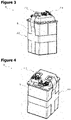
- the carrying belt (2.3) can be fixed at the upper part of the battery (B) with the strap stabilizer (2.5) located at the belt tip (2.3.1) of the carrying belt (2.3) ( Figure 4 ).
- the carrying belt (2.3) is extended over the two parallel edges of the battery (B).
- the carrying belt (2.3) located on the carrying strap (2) ensures that the battery (B) is placed on the carrying arm (3.1) on the carrier (3).
- the carrying belt (2.3) comprises the belt tip (2.3.1) and the support slot (2.3.2).
- the carrying belt (2.3) ensures that the weight of the battery (B) is balanced when it is placed on the carrying arm (3.1).
- the carrying belt (2.3) hangs upwards from the two parallel edges of the battery (B).
- the carrying belts (2.3) can be fixed on the battery (B) by means of strap stabilizers (2.5).
- the carrying belts (2.3) are placed on the carrying arm (3.1) from the tips of the belts (2.3.1).
- a support slot (2.3.2) is found at the belt tips (2.3.1).
- the support slots (2.3.2) of the carrying belts (2.3) are attached to the carrying arm (3.1).
- the carrying belt (2.3) is extended over the two parallel edges of the battery (B).
- the battery (B), placed on the carrying strap (2) is passed from the carrying belt (2.3) to the carrying arm (3.1) of the carrier (3) when it is preferred to be carried to the vehicle.
- the battery (B) is passed from the support slot (2.3.2) of the carrying belt (2.3) to the carrying arm (3.1).
- the carrying arm (3.1) contacts the carrying support (2.4) located in the support slot (2.3.2).
- the carrying support (2.4) is placed in the support slots (2.3.2) in the carrying belts (2.3).
- the carrying support (2.4) of the invention prevents the carrying belts (2.3) from being damaged if they are placed on the carrying arm (3.1).
- the carrying support (2.4) is inserted into the support slot (2.3.2) in the carrier belts (2.3).
- the carrying support (2.4) is preferably manufactured in metal or steel form.
- the carrying support (2.4) is preferably in a rectangular geometric form.
- the carrying support (2.4) is in the same geometric form as the support slot (2.3.2).
- the carrying support (2.4) prevents the carrying strap (2) from being damaged during the carrying of the battery (B) together with the carrying strap (2).
- the carrying support (2.4) ensures that the weight of the battery (B) is distributed evenly on the carrying straps (2.3) while being carried with the carrying strap (2). Thanks to its rectangular geometric form, the carrying support (2.4) prevents the battery (B) it carries from oscillating while being carried.
- the carrying belt (2.3) in case the battery (B) is stationary and not placed in a vehicle, the carrying belt (2.3) can be fixed at the upper part of the battery (B) with the strap stabilizer (2.5) located at the belt tip (2.3.1) of the carrying belt (2.3) ( Figure 4 ).
- the strap stabilizer (2.5) preferably has a hook-and-loop fastening feature.
- the part to which the strap stabilizer (2.5) is affixed is preferably located on the upper surface of the battery (B). The function of the strap stabilizer (2.5) ensures that the carrying strap (2) is stationary while the battery (B) is performing the operation.
- the carrier (3) in an embodiment of the invention enables the battery (B) to move.
- the carrier (3) comprises the carrying arm (3.1), the lifting profile (3.2) and the carrying foot (3.3).
- the carrier (3) is the part in which the carrying strap (2), in which the battery (B) is placed, is inserted into the carrying arm (3.1).
- the carrier (3) enables the carrying arm (3.1) to be moved up or down perpendicular to the ground by means of the lifting profile (3.2).
- the carrier (3) prevents the battery (B) attached to the carrying arm (3.1) from moving on the horizontal axis, and enables it to be moved up or down perpendicular to the ground via the lifting profile (3.2).
- the carrying arm (3.1) located on the carrier (3) ensures that the battery (B) remains fixed and balanced by means of the carrying strap (2). It comprises the carrying arm (3.1), the fixing tip (3.1.1), the blocking clearance (3.1.2) and the blocking pin (3.1.3). After the battery (B) is placed on the carrying arm (3.1), the blocking pin (3.1.3) is inserted into the blocking clearance (3.1.2) in order to prevent the battery (B) from being separated from the carrying strap (2) together with the carrying arm (3.1).
- the fixing tip (3.1.1) of the carrying arm (3.1) ensures that the carrying arm (3.1) is fixed to the lifting profile (3.2).
- the blocking pin (3.1.3) is designed to prevent the carrying arm (3.1) from coming off after it passes through the carrying strap (2).
- the lifting profile (3.2) on the carrier (3) preferably works with the logic of a lever jack.
- the lifting profile (3.2) comprises the fixed arm (3.2.1), the first movable arm (3.2.2), the second movable arm (3.2.3) and the motion provider (3.2.4).
- the lifting profile (3.2), which is connected to the carrying arm (3.1), is opened upwards on the vertical axis by means of the motion provider (3.2.4).
- the second movable arm (3.2.3) is in the first movable arm (3.2.2) and the first movable arm (3.2.2) is nested inside the fixed arm (3.2.1).
- the motion provider (3.2.4) When the motion provider (3.2.4) is rotated in one direction around its central axis by the user, the first movable arm (3.2.2) moves in the vertical axis upwards within the fixed arm (3.2.1). When the first movable arm (3.2.2) is completely removed from the fixed arm (3.2.1), as the motion provider (3.2.4) is rotated by the user around its central axis in one direction, the second movable arm (3.2.3) is moved in upward direction on the vertical axis within the first movable arm (3.2.2). The motion provider (3.2.4) is rotated by the user around its central axis in one direction or the other, and the plane to be placed is adjusted according to the size of the vehicle in which the battery (B) will be placed.
- the carrier (3) is brought closer to the vehicle by means of the carrying wheels (3.3.1) on the carrier foot (3.3) by applying force thereon.
- the position where the battery (B) will be placed is selected and the motion provider (3.2.4) is used again.
- the motion provider (3.2.4) is rotated around its central axis in another direction, and the first movable arm (3.2.2) moves down the vertical axis within the fixed arm (3.2.1).
- the battery (B) can be placed into or removed from the vehicle by moving it only in the vertical direction by means of the carrier (3).
- the carrying leg (3.3) located on the carrier (3) enables the battery (B) to be carried from one place to another.
- the carrying leg (3.3) comprises the carrying wheel (3.3.1).
- a lifting profile (3.2) is found at one end of the carrying leg (3.3).
- the free part of the carrying leg (3.3) can get under a vehicle or a material.
- the "carrying straps (2)" are separated from the strap stabilizers (2.5) after the vehicle seat is opened. Then the carrier (3) is brought to the side of the vehicle with the help of the carrying wheels (3.3.1). The ones in front of the carrying wheels (3.3.1) of the carrier (3) are slid towards the bottom of the vehicle. Meanwhile, the carrying arm (3.1) is passed through the support slots (2.3.2) of the carrying strap (2). Then, the blocking pin (3.1.3) is inserted into the blocking clearance (3.1.2) to prevent the holding straps (2) from coming out of the carrying arm (3.1).
- the first movable arm (3.2.2) and the second movable arm (3.2.3), which are nested in the fixed arm (3.2.1) in the lifting profile (3.2), are provided to move upwards in the vertical axis.
- the process of removing the battery (B) located in the carrying straps (2) begins. After the lower point of the battery (B) is separated from the upper point of the vehicle on the vertical axis, the lifting process of the lifting profile (3.2) stops and the battery (B) is carried to the desired location by the rotating the carrying wheels (3.3.1) under the carrier (3).
- the lifting profile (3.2) is moved downwards by means of the motion provider (3.2.4) on the vertical axis of the first movable arm (3.2.2) and the second movable arm (3.2.3), which are nested in the fixed arm (3.2.1).
- the battery (B) is lowered towards the vehicle in the preferred position.
- the blocking pin (3.1.3) is removed from the blocking clearance (3.1.2).
- the carrying arm (3.1) is slowly pulled back and removed from the carrying belt (2.3) of the carrying strap (2).
- the strap stabilizers (2.5) on the carrying belt (2.3) of the carrying straps (2) are fixed to the Velcro straps on the battery (B) cover. In this way, the carrying straps (2.3) of the carrying strap (2) are prevented from making noise and hitting the surrounding parts by standing idle.
- this portable carrying mechanism (1) can be carried in the luggage compartments of light commercial vehicles by reducing the lifting profile (3.2) when not in use. In this way, it can be carried for replacing the batteries (B) of vehicles that require battery replacement due to a dead battery, technical problems etc. reasons.
- the battery (B) is placed inside the carrying strap (2).
- the battery (B) is placed in the insertion clearance (2.1) in the carrying strap (2).
- the containment belt (2.2) wraps around the battery (B).
- the carrying belt (2.3) remains at the end part of the battery (B).
- the carrying belt (2.3) can be fixed at the upper part of the battery (B) with the strap stabilizer (2.5) located at the belt tip (2.3.1) of the carrying belt (2.3) ( Figure 4 ).
- the carrying belt (2.3) is extended over the two parallel edges of the battery (B).
- the battery (B), placed on the carrying strap (2), is passed from the carrying belt (2.3) to the carrying arm (3.1) of the carrier (3) when it is preferred to be carried to the vehicle.
- the battery (B) is passed from the support slot (2.3.2) of the carrying belt (2.3) to the carrying arm (3.1).
- the carrying arm (3.1) contacts the carrying support (2.4) located in the support slot (2.3.2).
- the blocking pin (3.1.3) is inserted into the blocking clearance (3.1.2) in order to prevent the battery (B) from being separated from the carrying strap (2) together with the carrying arm (3.1).
- the carrier (3) enables the battery (B) to be lifted on the vertical axis according to the size of the vehicle where the battery (B) will be placed.
- the lifting profile (3.2) which is connected to the carrying arm (3.1), is opened upwards on the vertical axis by means of the motion provider (3.2.4).
- the second movable arm (3.2.3) is in the first movable arm (3.2.2) and the first movable arm (3.2.2) is nested inside the fixed arm (3.2.1).
- the motion provider (3.2.4) When the motion provider (3.2.4) is rotated in one direction around its central axis by the user, the first movable arm (3.2.2) moves in the vertical axis upwards within the fixed arm (3.2.1). When the first movable arm (3.2.2) is completely removed from the fixed arm (3.2.1), as the motion provider (3.2.4) is rotated by the user around its central axis in one direction, the second movable arm (3.2.3) is moved in upward direction on the vertical axis within the first movable arm (3.2.2). The motion provider (3.2.4) is rotated by the user around its central axis in one direction or the other, and the plane to be placed is adjusted according to the size of the vehicle in which the battery (B) will be placed.
- the carrier (3) is brought closer to the vehicle by means of the carrying wheels (3.3.1) on the carrier foot (3.3) by applying force thereon.
- the position where the battery (B) will be placed is selected and the motion provider (3.2.4) is used again.
- the motion provider (3.2.4) is rotated around its central axis in another direction, and the first movable arm (3.2.2) moves down the vertical axis within the fixed arm (3.2.1).
- the battery (B) can be placed into or removed from the vehicle by moving it only in the vertical direction by means of the carrier (3).
- the carrying mechanism (1) in this embodiment of the invention is carried out as follows.
- the battery (B) is placed inside the carrying strap (2).
- the battery (B) is placed in the insertion clearance (2.1) in the carrying strap (2).
- the containment belt (2.2) wraps around the battery (B).
- the carrying belt (2.3) remains at the end part of the battery (B).
- the carrying belt (2.3) can be fixed at the upper part of the battery (B) with the strap stabilizer (2.5) located at the belt tip (2.3.1) of the carrying belt (2.3) ( Figure 4 ).
- the carrying belt (2.3) is extended over the two parallel edges of the battery (B).
- the battery (B), placed on the carrying strap (2), is passed from the carrying belt (2.3) to the carrying arm (3.1) of the carrier (3) when it is preferred to be carried to the vehicle.
- the battery (B) is passed from the support slot (2.3.2) of the carrying belt (2.3) to the carrying arm (3.1).
- the carrying arm (3.1) contacts the carrying support (2.4) located in the support slot (2.3.2).
- the carrying strap (2) found on the battery (B) to the carrying arm (3.1) with the carrying belt (2.3)
- the blocking pin (3.1.3) is inserted into the blocking clearance (3.1.2) in order to prevent the battery (B) from being separated from the carrying strap (2) together with the carrying arm (3.1).
- the carrier (3) After the battery (B) is fixed in the carrying strap (2), the carrier (3) enables the battery (B) to be lifted on the vertical axis according to the size of the vehicle where the battery (B) will be placed.
- the lifting profile (3.2), which is connected to the carrying arm (3.1), is opened upwards on the vertical axis by means of the motion provider (3.2.4).
- the second movable arm (3.2.3) In case the lifting profile (3.2) is closed, the second movable arm (3.2.3) is in the first movable arm (3.2.2) and the first movable arm (3.2.2) is nested inside the fixed arm (3.2.1).
- the motion provider (3.2.4) When the motion provider (3.2.4) is rotated in one direction around its central axis by the user, the first movable arm (3.2.2) moves in the vertical axis upwards within the fixed arm (3.2.1). When the first movable arm (3.2.2) is completely removed from the fixed arm (3.2.1), as the motion provider (3.2.4) is rotated by the user around its central axis in one direction, the second movable arm (3.2.3) is moved in upward direction on the vertical axis within the first movable arm (3.2.2). The motion provider (3.2.4) is rotated by the user around its central axis in one direction or the other, and the plane to be placed is adjusted according to the size of the vehicle in which the battery (B) will be placed.
- the carrier (3) is brought closer to the vehicle by means of the carrying wheels (3.3.1) on the carrier foot (3.3) by applying force thereon.
- the position where the battery (B) will be placed is selected and the motion provider (3.2.4) is used again.
- the motion provider (3.2.4) is rotated around its central axis in another direction, and the first movable arm (3.2.2) moves down the vertical axis within the fixed arm (3.2.1).
- the battery (B) can be placed into or removed from the vehicle by moving it only in the vertical direction by means of the carrier (3).
Landscapes
- Engineering & Computer Science (AREA)
- Mechanical Engineering (AREA)
- Transportation (AREA)
- Structural Engineering (AREA)
- Chemical & Material Sciences (AREA)
- Combustion & Propulsion (AREA)
- Power Engineering (AREA)
- Civil Engineering (AREA)
- Life Sciences & Earth Sciences (AREA)
- Geology (AREA)
- Battery Mounting, Suspending (AREA)
Applications Claiming Priority (1)
| Application Number | Priority Date | Filing Date | Title |
|---|---|---|---|
| TR202102219 | 2021-02-17 |
Publications (2)
| Publication Number | Publication Date |
|---|---|
| EP4046881A1 true EP4046881A1 (fr) | 2022-08-24 |
| EP4046881B1 EP4046881B1 (fr) | 2024-01-24 |
Family
ID=80447532
Family Applications (1)
| Application Number | Title | Priority Date | Filing Date |
|---|---|---|---|
| EP22156437.0A Active EP4046881B1 (fr) | 2021-02-17 | 2022-02-11 | Mécanisme de support |
Country Status (2)
| Country | Link |
|---|---|
| EP (1) | EP4046881B1 (fr) |
| ES (1) | ES2975141T3 (fr) |
Cited By (2)
| Publication number | Priority date | Publication date | Assignee | Title |
|---|---|---|---|---|
| DE10341542A1 (de) | 2003-09-09 | 2005-04-14 | BSH Bosch und Siemens Hausgeräte GmbH | Getränkezubereitungsvorrichtung |
| CN116176743A (zh) * | 2023-03-23 | 2023-05-30 | 雅迪科技集团有限公司 | 电动二轮车电池安装结构及换电方法 |
Citations (12)
| Publication number | Priority date | Publication date | Assignee | Title |
|---|---|---|---|---|
| US2775476A (en) * | 1953-08-10 | 1956-12-25 | East Penn Mfg | Self-tightening and gripping battery lifter |
| US2847243A (en) * | 1956-07-10 | 1958-08-12 | Aaron H Hare | Battery lifter |
| US4042054A (en) * | 1975-12-18 | 1977-08-16 | Ward Eugene T | Vehicle and battery pack |
| US4042762A (en) * | 1975-02-12 | 1977-08-16 | Gould Inc. | Handle for plastic batteries |
| US4527823A (en) * | 1982-07-26 | 1985-07-09 | Straus Stephen H | Battery carrier |
| US5372899A (en) * | 1994-03-16 | 1994-12-13 | At&T Corp. | Battery handle |
| DE102011111537A1 (de) | 2011-08-31 | 2013-02-28 | Alf Zips | Wiederaufladbare Batterie und ein Elektrofahrzeug |
| US20180151860A1 (en) | 2015-04-08 | 2018-05-31 | Ujet Vehicles S.À.R.L. | Quick-exchange battery assembly, and motor vehicle, in particular motor scooter |
| CN109050765A (zh) * | 2018-08-23 | 2018-12-21 | 杭州容大智造科技有限公司 | 一种电动车及其电池的顶升平移更换装置 |
| CN210258092U (zh) | 2019-05-09 | 2020-04-07 | 石狮市鹏工汽车教学设备有限公司 | 一种适用于汽车新能源电池的搬运设备 |
| WO2020194985A1 (fr) * | 2019-03-25 | 2020-10-01 | 本田技研工業株式会社 | Structure d'attachement/de détachement de batterie pour véhicule électrique de type à selle |
| CN211971639U (zh) * | 2020-04-03 | 2020-11-20 | 福州天泽永汇环境科技有限公司 | 一种电池转运小车 |
-
2022
- 2022-02-11 EP EP22156437.0A patent/EP4046881B1/fr active Active
- 2022-02-11 ES ES22156437T patent/ES2975141T3/es active Active
Patent Citations (12)
| Publication number | Priority date | Publication date | Assignee | Title |
|---|---|---|---|---|
| US2775476A (en) * | 1953-08-10 | 1956-12-25 | East Penn Mfg | Self-tightening and gripping battery lifter |
| US2847243A (en) * | 1956-07-10 | 1958-08-12 | Aaron H Hare | Battery lifter |
| US4042762A (en) * | 1975-02-12 | 1977-08-16 | Gould Inc. | Handle for plastic batteries |
| US4042054A (en) * | 1975-12-18 | 1977-08-16 | Ward Eugene T | Vehicle and battery pack |
| US4527823A (en) * | 1982-07-26 | 1985-07-09 | Straus Stephen H | Battery carrier |
| US5372899A (en) * | 1994-03-16 | 1994-12-13 | At&T Corp. | Battery handle |
| DE102011111537A1 (de) | 2011-08-31 | 2013-02-28 | Alf Zips | Wiederaufladbare Batterie und ein Elektrofahrzeug |
| US20180151860A1 (en) | 2015-04-08 | 2018-05-31 | Ujet Vehicles S.À.R.L. | Quick-exchange battery assembly, and motor vehicle, in particular motor scooter |
| CN109050765A (zh) * | 2018-08-23 | 2018-12-21 | 杭州容大智造科技有限公司 | 一种电动车及其电池的顶升平移更换装置 |
| WO2020194985A1 (fr) * | 2019-03-25 | 2020-10-01 | 本田技研工業株式会社 | Structure d'attachement/de détachement de batterie pour véhicule électrique de type à selle |
| CN210258092U (zh) | 2019-05-09 | 2020-04-07 | 石狮市鹏工汽车教学设备有限公司 | 一种适用于汽车新能源电池的搬运设备 |
| CN211971639U (zh) * | 2020-04-03 | 2020-11-20 | 福州天泽永汇环境科技有限公司 | 一种电池转运小车 |
Cited By (2)
| Publication number | Priority date | Publication date | Assignee | Title |
|---|---|---|---|---|
| DE10341542A1 (de) | 2003-09-09 | 2005-04-14 | BSH Bosch und Siemens Hausgeräte GmbH | Getränkezubereitungsvorrichtung |
| CN116176743A (zh) * | 2023-03-23 | 2023-05-30 | 雅迪科技集团有限公司 | 电动二轮车电池安装结构及换电方法 |
Also Published As
| Publication number | Publication date |
|---|---|
| ES2975141T3 (es) | 2024-07-03 |
| EP4046881B1 (fr) | 2024-01-24 |
Similar Documents
| Publication | Publication Date | Title |
|---|---|---|
| EP4046881B1 (fr) | Mécanisme de support | |
| US2775489A (en) | Scaffold | |
| KR102005705B1 (ko) | 가스통 운반기구 | |
| CN209835493U (zh) | 一种光电控制手柄 | |
| CA2984015A1 (fr) | Piece d'ancrage de maille de grille | |
| AU2023237044B1 (en) | Tool station | |
| KR20120070304A (ko) | 지게차의 안전작업을 위한 카메라 장치 | |
| CN216222678U (zh) | 一种车顶作业安全操作架 | |
| KR200450087Y1 (ko) | 저유소 출하대의 작업자 추락 방지 안전장치 | |
| KR102639574B1 (ko) | 안전 시스템 | |
| KR101417298B1 (ko) | 화물보호아대의 설치기구 | |
| CN220245248U (zh) | 一种组合式机箱用吊装装置 | |
| KR101841510B1 (ko) | 항공기 사출좌석 장탈착 장비 | |
| CN211769932U (zh) | 一种塔式起重机的伸缩式侧向防护装置 | |
| TR2021002219A1 (tr) | Bi̇r taşima mekani̇zmasi | |
| KR101805127B1 (ko) | 차량 탈부착용 리프트 | |
| CN214834570U (zh) | 一种可移动的通信检修操作台 | |
| JPH0711463U (ja) | バッテリー交換装置 | |
| KR950005363B1 (ko) | 화물승강운반기 | |
| CN212286555U (zh) | 一种发动机飞轮辅助安装工装 | |
| KR102101165B1 (ko) | 사다리와 결합하는 조립용 이송장치 | |
| KR101948540B1 (ko) | 화물차용 아대 설치기구 | |
| US3818709A (en) | Protective cage for trench workers | |
| JP3224767U (ja) | 容器持上げ傾動装置、およびフック | |
| CN221093653U (zh) | 一种带有防护坠落机构的高空车底盘用吊具 |
Legal Events
| Date | Code | Title | Description |
|---|---|---|---|
| PUAI | Public reference made under article 153(3) epc to a published international application that has entered the european phase |
Free format text: ORIGINAL CODE: 0009012 |
|
| STAA | Information on the status of an ep patent application or granted ep patent |
Free format text: STATUS: THE APPLICATION HAS BEEN PUBLISHED |
|
| AK | Designated contracting states |
Kind code of ref document: A1 Designated state(s): AL AT BE BG CH CY CZ DE DK EE ES FI FR GB GR HR HU IE IS IT LI LT LU LV MC MK MT NL NO PL PT RO RS SE SI SK SM TR |
|
| STAA | Information on the status of an ep patent application or granted ep patent |
Free format text: STATUS: REQUEST FOR EXAMINATION WAS MADE |
|
| 17P | Request for examination filed |
Effective date: 20221011 |
|
| RBV | Designated contracting states (corrected) |
Designated state(s): AL AT BE BG CH CY CZ DE DK EE ES FI FR GB GR HR HU IE IS IT LI LT LU LV MC MK MT NL NO PL PT RO RS SE SI SK SM TR |
|
| P01 | Opt-out of the competence of the unified patent court (upc) registered |
Effective date: 20230619 |
|
| GRAP | Despatch of communication of intention to grant a patent |
Free format text: ORIGINAL CODE: EPIDOSNIGR1 |
|
| STAA | Information on the status of an ep patent application or granted ep patent |
Free format text: STATUS: GRANT OF PATENT IS INTENDED |
|
| INTG | Intention to grant announced |
Effective date: 20231018 |
|
| GRAS | Grant fee paid |
Free format text: ORIGINAL CODE: EPIDOSNIGR3 |
|
| GRAA | (expected) grant |
Free format text: ORIGINAL CODE: 0009210 |
|
| STAA | Information on the status of an ep patent application or granted ep patent |
Free format text: STATUS: THE PATENT HAS BEEN GRANTED |
|
| AK | Designated contracting states |
Kind code of ref document: B1 Designated state(s): AL AT BE BG CH CY CZ DE DK EE ES FI FR GB GR HR HU IE IS IT LI LT LU LV MC MK MT NL NO PL PT RO RS SE SI SK SM TR |
|
| REG | Reference to a national code |
Ref country code: GB Ref legal event code: FG4D |
|
| REG | Reference to a national code |
Ref country code: CH Ref legal event code: EP |
|
| REG | Reference to a national code |
Ref country code: IE Ref legal event code: FG4D |
|
| REG | Reference to a national code |
Ref country code: DE Ref legal event code: R096 Ref document number: 602022001634 Country of ref document: DE |
|
| REG | Reference to a national code |
Ref country code: LT Ref legal event code: MG9D |
|
| REG | Reference to a national code |
Ref country code: NL Ref legal event code: MP Effective date: 20240124 |
|
| PG25 | Lapsed in a contracting state [announced via postgrant information from national office to epo] |
Ref country code: NL Free format text: LAPSE BECAUSE OF FAILURE TO SUBMIT A TRANSLATION OF THE DESCRIPTION OR TO PAY THE FEE WITHIN THE PRESCRIBED TIME-LIMIT Effective date: 20240124 |
|
| PG25 | Lapsed in a contracting state [announced via postgrant information from national office to epo] |
Ref country code: NL Free format text: LAPSE BECAUSE OF FAILURE TO SUBMIT A TRANSLATION OF THE DESCRIPTION OR TO PAY THE FEE WITHIN THE PRESCRIBED TIME-LIMIT Effective date: 20240124 |
|
| PG25 | Lapsed in a contracting state [announced via postgrant information from national office to epo] |
Ref country code: IS Free format text: LAPSE BECAUSE OF FAILURE TO SUBMIT A TRANSLATION OF THE DESCRIPTION OR TO PAY THE FEE WITHIN THE PRESCRIBED TIME-LIMIT Effective date: 20240524 |
|
| REG | Reference to a national code |
Ref country code: ES Ref legal event code: FG2A Ref document number: 2975141 Country of ref document: ES Kind code of ref document: T3 Effective date: 20240703 |
|
| PG25 | Lapsed in a contracting state [announced via postgrant information from national office to epo] |
Ref country code: LT Free format text: LAPSE BECAUSE OF FAILURE TO SUBMIT A TRANSLATION OF THE DESCRIPTION OR TO PAY THE FEE WITHIN THE PRESCRIBED TIME-LIMIT Effective date: 20240124 |
|
| PG25 | Lapsed in a contracting state [announced via postgrant information from national office to epo] |
Ref country code: GR Free format text: LAPSE BECAUSE OF FAILURE TO SUBMIT A TRANSLATION OF THE DESCRIPTION OR TO PAY THE FEE WITHIN THE PRESCRIBED TIME-LIMIT Effective date: 20240425 |
|
| REG | Reference to a national code |
Ref country code: AT Ref legal event code: MK05 Ref document number: 1651957 Country of ref document: AT Kind code of ref document: T Effective date: 20240124 |
|
| PG25 | Lapsed in a contracting state [announced via postgrant information from national office to epo] |
Ref country code: RS Free format text: LAPSE BECAUSE OF FAILURE TO SUBMIT A TRANSLATION OF THE DESCRIPTION OR TO PAY THE FEE WITHIN THE PRESCRIBED TIME-LIMIT Effective date: 20240424 Ref country code: HR Free format text: LAPSE BECAUSE OF FAILURE TO SUBMIT A TRANSLATION OF THE DESCRIPTION OR TO PAY THE FEE WITHIN THE PRESCRIBED TIME-LIMIT Effective date: 20240124 |
|
| PG25 | Lapsed in a contracting state [announced via postgrant information from national office to epo] |
Ref country code: AT Free format text: LAPSE BECAUSE OF FAILURE TO SUBMIT A TRANSLATION OF THE DESCRIPTION OR TO PAY THE FEE WITHIN THE PRESCRIBED TIME-LIMIT Effective date: 20240124 |
|
| PG25 | Lapsed in a contracting state [announced via postgrant information from national office to epo] |
Ref country code: RS Free format text: LAPSE BECAUSE OF FAILURE TO SUBMIT A TRANSLATION OF THE DESCRIPTION OR TO PAY THE FEE WITHIN THE PRESCRIBED TIME-LIMIT Effective date: 20240424 Ref country code: NO Free format text: LAPSE BECAUSE OF FAILURE TO SUBMIT A TRANSLATION OF THE DESCRIPTION OR TO PAY THE FEE WITHIN THE PRESCRIBED TIME-LIMIT Effective date: 20240424 Ref country code: LT Free format text: LAPSE BECAUSE OF FAILURE TO SUBMIT A TRANSLATION OF THE DESCRIPTION OR TO PAY THE FEE WITHIN THE PRESCRIBED TIME-LIMIT Effective date: 20240124 Ref country code: IS Free format text: LAPSE BECAUSE OF FAILURE TO SUBMIT A TRANSLATION OF THE DESCRIPTION OR TO PAY THE FEE WITHIN THE PRESCRIBED TIME-LIMIT Effective date: 20240524 Ref country code: HR Free format text: LAPSE BECAUSE OF FAILURE TO SUBMIT A TRANSLATION OF THE DESCRIPTION OR TO PAY THE FEE WITHIN THE PRESCRIBED TIME-LIMIT Effective date: 20240124 Ref country code: GR Free format text: LAPSE BECAUSE OF FAILURE TO SUBMIT A TRANSLATION OF THE DESCRIPTION OR TO PAY THE FEE WITHIN THE PRESCRIBED TIME-LIMIT Effective date: 20240425 Ref country code: FI Free format text: LAPSE BECAUSE OF FAILURE TO SUBMIT A TRANSLATION OF THE DESCRIPTION OR TO PAY THE FEE WITHIN THE PRESCRIBED TIME-LIMIT Effective date: 20240124 Ref country code: BG Free format text: LAPSE BECAUSE OF FAILURE TO SUBMIT A TRANSLATION OF THE DESCRIPTION OR TO PAY THE FEE WITHIN THE PRESCRIBED TIME-LIMIT Effective date: 20240124 Ref country code: AT Free format text: LAPSE BECAUSE OF FAILURE TO SUBMIT A TRANSLATION OF THE DESCRIPTION OR TO PAY THE FEE WITHIN THE PRESCRIBED TIME-LIMIT Effective date: 20240124 |
|
| PG25 | Lapsed in a contracting state [announced via postgrant information from national office to epo] |
Ref country code: PL Free format text: LAPSE BECAUSE OF FAILURE TO SUBMIT A TRANSLATION OF THE DESCRIPTION OR TO PAY THE FEE WITHIN THE PRESCRIBED TIME-LIMIT Effective date: 20240124 Ref country code: PT Free format text: LAPSE BECAUSE OF FAILURE TO SUBMIT A TRANSLATION OF THE DESCRIPTION OR TO PAY THE FEE WITHIN THE PRESCRIBED TIME-LIMIT Effective date: 20240524 |
|
| PG25 | Lapsed in a contracting state [announced via postgrant information from national office to epo] |
Ref country code: SE Free format text: LAPSE BECAUSE OF FAILURE TO SUBMIT A TRANSLATION OF THE DESCRIPTION OR TO PAY THE FEE WITHIN THE PRESCRIBED TIME-LIMIT Effective date: 20240124 Ref country code: PT Free format text: LAPSE BECAUSE OF FAILURE TO SUBMIT A TRANSLATION OF THE DESCRIPTION OR TO PAY THE FEE WITHIN THE PRESCRIBED TIME-LIMIT Effective date: 20240524 Ref country code: PL Free format text: LAPSE BECAUSE OF FAILURE TO SUBMIT A TRANSLATION OF THE DESCRIPTION OR TO PAY THE FEE WITHIN THE PRESCRIBED TIME-LIMIT Effective date: 20240124 Ref country code: LV Free format text: LAPSE BECAUSE OF FAILURE TO SUBMIT A TRANSLATION OF THE DESCRIPTION OR TO PAY THE FEE WITHIN THE PRESCRIBED TIME-LIMIT Effective date: 20240124 |
|
| PG25 | Lapsed in a contracting state [announced via postgrant information from national office to epo] |
Ref country code: DK Free format text: LAPSE BECAUSE OF FAILURE TO SUBMIT A TRANSLATION OF THE DESCRIPTION OR TO PAY THE FEE WITHIN THE PRESCRIBED TIME-LIMIT Effective date: 20240124 |
|
| PG25 | Lapsed in a contracting state [announced via postgrant information from national office to epo] |
Ref country code: SM Free format text: LAPSE BECAUSE OF FAILURE TO SUBMIT A TRANSLATION OF THE DESCRIPTION OR TO PAY THE FEE WITHIN THE PRESCRIBED TIME-LIMIT Effective date: 20240124 |
|
| PG25 | Lapsed in a contracting state [announced via postgrant information from national office to epo] |
Ref country code: LU Free format text: LAPSE BECAUSE OF NON-PAYMENT OF DUE FEES Effective date: 20240211 |
|
| PG25 | Lapsed in a contracting state [announced via postgrant information from national office to epo] |
Ref country code: EE Free format text: LAPSE BECAUSE OF FAILURE TO SUBMIT A TRANSLATION OF THE DESCRIPTION OR TO PAY THE FEE WITHIN THE PRESCRIBED TIME-LIMIT Effective date: 20240124 Ref country code: CZ Free format text: LAPSE BECAUSE OF FAILURE TO SUBMIT A TRANSLATION OF THE DESCRIPTION OR TO PAY THE FEE WITHIN THE PRESCRIBED TIME-LIMIT Effective date: 20240124 |
|
| REG | Reference to a national code |
Ref country code: DE Ref legal event code: R097 Ref document number: 602022001634 Country of ref document: DE |
|
| PG25 | Lapsed in a contracting state [announced via postgrant information from national office to epo] |
Ref country code: SK Free format text: LAPSE BECAUSE OF FAILURE TO SUBMIT A TRANSLATION OF THE DESCRIPTION OR TO PAY THE FEE WITHIN THE PRESCRIBED TIME-LIMIT Effective date: 20240124 |
|
| PG25 | Lapsed in a contracting state [announced via postgrant information from national office to epo] |
Ref country code: SM Free format text: LAPSE BECAUSE OF FAILURE TO SUBMIT A TRANSLATION OF THE DESCRIPTION OR TO PAY THE FEE WITHIN THE PRESCRIBED TIME-LIMIT Effective date: 20240124 Ref country code: SK Free format text: LAPSE BECAUSE OF FAILURE TO SUBMIT A TRANSLATION OF THE DESCRIPTION OR TO PAY THE FEE WITHIN THE PRESCRIBED TIME-LIMIT Effective date: 20240124 Ref country code: LU Free format text: LAPSE BECAUSE OF NON-PAYMENT OF DUE FEES Effective date: 20240211 Ref country code: EE Free format text: LAPSE BECAUSE OF FAILURE TO SUBMIT A TRANSLATION OF THE DESCRIPTION OR TO PAY THE FEE WITHIN THE PRESCRIBED TIME-LIMIT Effective date: 20240124 Ref country code: DK Free format text: LAPSE BECAUSE OF FAILURE TO SUBMIT A TRANSLATION OF THE DESCRIPTION OR TO PAY THE FEE WITHIN THE PRESCRIBED TIME-LIMIT Effective date: 20240124 Ref country code: CZ Free format text: LAPSE BECAUSE OF FAILURE TO SUBMIT A TRANSLATION OF THE DESCRIPTION OR TO PAY THE FEE WITHIN THE PRESCRIBED TIME-LIMIT Effective date: 20240124 |
|
| PG25 | Lapsed in a contracting state [announced via postgrant information from national office to epo] |
Ref country code: MC Free format text: LAPSE BECAUSE OF FAILURE TO SUBMIT A TRANSLATION OF THE DESCRIPTION OR TO PAY THE FEE WITHIN THE PRESCRIBED TIME-LIMIT Effective date: 20240124 |
|
| PG25 | Lapsed in a contracting state [announced via postgrant information from national office to epo] |
Ref country code: MC Free format text: LAPSE BECAUSE OF FAILURE TO SUBMIT A TRANSLATION OF THE DESCRIPTION OR TO PAY THE FEE WITHIN THE PRESCRIBED TIME-LIMIT Effective date: 20240124 |
|
| PLBE | No opposition filed within time limit |
Free format text: ORIGINAL CODE: 0009261 |
|
| STAA | Information on the status of an ep patent application or granted ep patent |
Free format text: STATUS: NO OPPOSITION FILED WITHIN TIME LIMIT |
|
| REG | Reference to a national code |
Ref country code: BE Ref legal event code: MM Effective date: 20240229 |
|
| 26N | No opposition filed |
Effective date: 20241025 |
|
| PG25 | Lapsed in a contracting state [announced via postgrant information from national office to epo] |
Ref country code: BE Free format text: LAPSE BECAUSE OF NON-PAYMENT OF DUE FEES Effective date: 20240229 |
|
| PG25 | Lapsed in a contracting state [announced via postgrant information from national office to epo] |
Ref country code: FR Free format text: LAPSE BECAUSE OF NON-PAYMENT OF DUE FEES Effective date: 20240324 |
|
| PG25 | Lapsed in a contracting state [announced via postgrant information from national office to epo] |
Ref country code: IE Free format text: LAPSE BECAUSE OF NON-PAYMENT OF DUE FEES Effective date: 20240211 |
|
| PG25 | Lapsed in a contracting state [announced via postgrant information from national office to epo] |
Ref country code: IE Free format text: LAPSE BECAUSE OF NON-PAYMENT OF DUE FEES Effective date: 20240211 Ref country code: FR Free format text: LAPSE BECAUSE OF NON-PAYMENT OF DUE FEES Effective date: 20240324 Ref country code: BE Free format text: LAPSE BECAUSE OF NON-PAYMENT OF DUE FEES Effective date: 20240229 |
|
| PG25 | Lapsed in a contracting state [announced via postgrant information from national office to epo] |
Ref country code: SI Free format text: LAPSE BECAUSE OF FAILURE TO SUBMIT A TRANSLATION OF THE DESCRIPTION OR TO PAY THE FEE WITHIN THE PRESCRIBED TIME-LIMIT Effective date: 20240124 |
|
| PG25 | Lapsed in a contracting state [announced via postgrant information from national office to epo] |
Ref country code: RO Free format text: LAPSE BECAUSE OF FAILURE TO SUBMIT A TRANSLATION OF THE DESCRIPTION OR TO PAY THE FEE WITHIN THE PRESCRIBED TIME-LIMIT Effective date: 20240124 |
|
| PG25 | Lapsed in a contracting state [announced via postgrant information from national office to epo] |
Ref country code: CY Free format text: LAPSE BECAUSE OF FAILURE TO SUBMIT A TRANSLATION OF THE DESCRIPTION OR TO PAY THE FEE WITHIN THE PRESCRIBED TIME-LIMIT; INVALID AB INITIO Effective date: 20220211 |
|
| REG | Reference to a national code |
Ref country code: CH Ref legal event code: PL |
|
| PG25 | Lapsed in a contracting state [announced via postgrant information from national office to epo] |
Ref country code: CH Free format text: LAPSE BECAUSE OF NON-PAYMENT OF DUE FEES Effective date: 20250228 |
|
| PG25 | Lapsed in a contracting state [announced via postgrant information from national office to epo] |
Ref country code: TR Free format text: LAPSE BECAUSE OF FAILURE TO SUBMIT A TRANSLATION OF THE DESCRIPTION OR TO PAY THE FEE WITHIN THE PRESCRIBED TIME-LIMIT Effective date: 20240124 |
|
| PGFP | Annual fee paid to national office [announced via postgrant information from national office to epo] |
Ref country code: ES Payment date: 20260317 Year of fee payment: 5 |
|
| PGFP | Annual fee paid to national office [announced via postgrant information from national office to epo] |
Ref country code: DE Payment date: 20260220 Year of fee payment: 5 |
|
| PGFP | Annual fee paid to national office [announced via postgrant information from national office to epo] |
Ref country code: IT Payment date: 20260220 Year of fee payment: 5 |