EP4046828B1 - Système et procédé de détection d'usure - Google Patents
Système et procédé de détection d'usure Download PDFInfo
- Publication number
- EP4046828B1 EP4046828B1 EP22162605.4A EP22162605A EP4046828B1 EP 4046828 B1 EP4046828 B1 EP 4046828B1 EP 22162605 A EP22162605 A EP 22162605A EP 4046828 B1 EP4046828 B1 EP 4046828B1
- Authority
- EP
- European Patent Office
- Prior art keywords
- transponder unit
- shielding
- unit
- friction
- friction element
- Prior art date
- Legal status (The legal status is an assumption and is not a legal conclusion. Google has not performed a legal analysis and makes no representation as to the accuracy of the status listed.)
- Active
Links
Images

Classifications
-
- F—MECHANICAL ENGINEERING; LIGHTING; HEATING; WEAPONS; BLASTING
- F16—ENGINEERING ELEMENTS AND UNITS; GENERAL MEASURES FOR PRODUCING AND MAINTAINING EFFECTIVE FUNCTIONING OF MACHINES OR INSTALLATIONS; THERMAL INSULATION IN GENERAL
- F16D—COUPLINGS FOR TRANSMITTING ROTATION; CLUTCHES; BRAKES
- F16D66/00—Arrangements for monitoring working conditions, e.g. wear, temperature
- F16D66/02—Apparatus for indicating wear
- F16D66/021—Apparatus for indicating wear using electrical detection or indication means
-
- B—PERFORMING OPERATIONS; TRANSPORTING
- B60—VEHICLES IN GENERAL
- B60C—VEHICLE TYRES; TYRE INFLATION; TYRE CHANGING; CONNECTING VALVES TO INFLATABLE ELASTIC BODIES IN GENERAL; DEVICES OR ARRANGEMENTS RELATED TO TYRES
- B60C11/00—Tyre tread bands; Tread patterns; Anti-skid inserts
- B60C11/24—Wear-indicating arrangements
- B60C11/246—Tread wear monitoring systems
-
- F—MECHANICAL ENGINEERING; LIGHTING; HEATING; WEAPONS; BLASTING
- F16—ENGINEERING ELEMENTS AND UNITS; GENERAL MEASURES FOR PRODUCING AND MAINTAINING EFFECTIVE FUNCTIONING OF MACHINES OR INSTALLATIONS; THERMAL INSULATION IN GENERAL
- F16D—COUPLINGS FOR TRANSMITTING ROTATION; CLUTCHES; BRAKES
- F16D66/00—Arrangements for monitoring working conditions, e.g. wear, temperature
- F16D66/02—Apparatus for indicating wear
- F16D66/021—Apparatus for indicating wear using electrical detection or indication means
- F16D66/026—Apparatus for indicating wear using electrical detection or indication means indicating different degrees of lining wear
-
- H—ELECTRICITY
- H01—ELECTRIC ELEMENTS
- H01R—ELECTRICALLY-CONDUCTIVE CONNECTIONS; STRUCTURAL ASSOCIATIONS OF A PLURALITY OF MUTUALLY-INSULATED ELECTRICAL CONNECTING ELEMENTS; COUPLING DEVICES; CURRENT COLLECTORS
- H01R39/00—Rotary current collectors, distributors or interrupters
- H01R39/02—Details for dynamo electric machines
- H01R39/58—Means structurally associated with the current collector for indicating condition thereof, e.g. for indicating brush wear
-
- H—ELECTRICITY
- H02—GENERATION; CONVERSION OR DISTRIBUTION OF ELECTRIC POWER
- H02K—DYNAMO-ELECTRIC MACHINES
- H02K11/00—Structural association of dynamo-electric machines with electric components or with devices for shielding, monitoring or protection
- H02K11/20—Structural association of dynamo-electric machines with electric components or with devices for shielding, monitoring or protection for measuring, monitoring, testing, protecting or switching
-
- H—ELECTRICITY
- H02—GENERATION; CONVERSION OR DISTRIBUTION OF ELECTRIC POWER
- H02K—DYNAMO-ELECTRIC MACHINES
- H02K5/00—Casings; Enclosures; Supports
- H02K5/04—Casings or enclosures characterised by the shape, form or construction thereof
- H02K5/14—Means for supporting or protecting brushes or brush holders
Definitions
- the invention relates to a wear detection system and a method for wear detection, in particular for friction elements such as brushes, friction linings, brake linings, lubricating pieces or the like, with at least one consumable friction element and a transponder unit, wherein the transponder unit can communicate wirelessly with a transmitting-receiving unit.
- Friction elements such as carbon brushes for electric motors, friction linings for power transmission, brake linings and solid lubricant pieces, are always subject to wear due to abrasion of the friction element material. It is often desirable to replace the friction element before it reaches a wear limit that impairs its function. Wear detection systems are therefore regularly used to monitor the wear status of friction elements. Electrical contacts on friction elements or switches that can signal when a wear limit is reached are well known here. However, such wear detection systems require wiring of the Contacts or switches with a control unit. Such wiring is relatively expensive to produce, especially if a large number of friction elements are to be monitored simultaneously. For example, wiring for brushes on a generator can be designed in a series circuit to reduce the wiring effort. However, the wear detection system can then no longer identify which brush triggered the signal in question.
- the known wear detection system has the disadvantage that the transponder unit must be destroyed when the wear limit is reached.
- the transponder unit must therefore be designed or attached to the carbon brush in such a way that it is reliably destroyed when the wear limit or the friction surface is reached.
- Inexpensive transponder units such as those available in label form, cannot therefore be used here, as the labels can come off due to heat in the immediate vicinity of the friction surface or cannot be mechanically destroyed due to poor adhesion to the carbon brush.
- transponder unit is additionally equipped with measuring sensors.
- the transponder unit can be attached to a friction element in any position that is suitable for installation, with the transponder unit being connected, for example, via a cable to a measuring sensor or a simple contact attached in the area of a wear limit of the friction element.
- Transponder units that need to be destroyed are therefore difficult to attach, and those that are equipped with measuring sensors and connecting cables are comparatively expensive.
- the present invention is therefore based on the object of proposing a wear detection system and a method for wear detection, which enables cost-effective and simple wear monitoring of friction elements.
- the wear detection system in particular for friction elements such as brushes, friction linings, brake linings, lubricating pieces or the like, comprises at least one consumable friction element and a transponder unit, wherein the transponder unit can communicate wirelessly with a transmitting-receiving unit, wherein the wear detection system has a shielding device, wherein the shielding device is designed such that the transponder unit can be at least partially shielded by means of the shielding device depending on a wear state of the friction element, such that communication between the transponder unit and the transmitting-receiving unit can be influenced, wherein the wear detection system comprises a holding device which is used for the movable positioning of the friction element relative to a friction surface serves, wherein the transponder unit is fixedly connected to the holding device, wherein the shielding device is designed as a shielding element arranged on the holding device, which can cover or uncover the transponder unit when a movement of the friction element occurs relative to the holding device.
- the transponder unit By influencing the transponder unit with an independently designed shielding device, it is possible to change, prevent or even enable a communication connection between the transponder unit and the transmitting/receiving unit. Since the signal received by the transponder unit from the transmitting/receiving unit is essentially influenced solely by the shielding device, almost any transponder unit, in particular a cost-effective transponder unit, can be used as a transponder unit. Furthermore, communication between the transponder unit and the transmitting/receiving unit is made significantly easier, since the content of the transmitted data is fundamentally irrelevant. It only matters that the transponder unit is detected or recognized by the transmitting/receiving unit.
- the transmission/reception unit can detect that the friction element has reached its wear limit by changing the response signal from the transponder unit or, alternatively, by the transponder signal not being received after it had previously been received or by a transponder signal not being received after it had previously been received.
- the wear detection system comprises a holding device which serves for the movable positioning of the friction element relative to a friction surface and for contacting the friction element with the friction surface.
- the friction element can therefore be held or received by the holding device and pressed against a friction surface with a pressing force, for example by means of a spring device or an actuator.
- the friction element can be monolithic with a cuboid shape or rod-shaped and can be received by the holding device in such a way that it can be moved essentially orthogonally to the friction surface in the holding device.
- the reduction in length and longitudinal movement of the friction element relative to the holding device caused by wear of the friction element can then influence the communication between the transponder unit and the transceiver unit by means of the shielding device.
- the transponder unit is connected in a fixed position to the holding device, wherein the shielding device is designed as a shielding element arranged on the holding device, which covers the transponder unit in a shielding manner or releases it when the friction element moves relative to the holding device.
- the transponder unit can, for example, be attached directly to a surface of the holding device without the transponder unit being in contact with the friction element.
- the shielding device is designed as a shielding element which, depending on a change in the length of the friction element, covers the transponder unit in a shielding manner or releases it for communication with the transceiver unit.
- the shielding element can, for example, be designed as a simple metal sheet which is moved relative to the transponder unit after one end of the friction element has passed through.
- a shielding device can also be designed inexpensively and enables particularly secure transmission or communication between the transponder unit and the transmitting/receiving unit, because the transponder unit is not exposed to high temperatures or vibrations due to the separation from the friction element.
- the holding device is made of a plastic material, a resonance frequency of, for example, an RFID transponder unit is then hardly influenced by surrounding materials with the exception of the shielding element.
- the transponder unit can have a code that can be received by the transceiver unit.
- the code can be used as a switching signal, for example to be able to start a machine. If a friction element is installed in the machine that does not have a predetermined code, a corresponding switching signal cannot be generated, so that as a result the machine cannot be started. This ensures that only friction elements approved for the machine can be used. If a large number of friction elements are used, it is also possible to determine which of the friction elements has failed or is worn if each friction element has an individual code using the transponder unit.
- the wear detection system can be connected to a control unit or a machine control system for such control purposes.
- the transponder unit can advantageously be an RFID transponder unit. It is also conceivable to use a transponder unit based on optical transmission technology, for example, but RFID transponder units are comparatively inexpensive and are also available in the form of an adhesive label. Passive RFID transponder units can preferably be used, as they do not require an external power supply. Furthermore, a radio signal between the RFID transponder unit and the transmitter-receiver unit can be easily influenced using the shielding device. In this way, a resonance frequency an antenna of the RFID transponder unit can easily be influenced by covering the antenna or by an electrical conductor near the antenna so that the radio signal is strongly attenuated or completely shielded.
- the friction element can be, for example, a contact piece for transmitting electrical energy, such as a carbon brush for an electric motor or generator.
- the wear detection system can be used effectively in particular when an electric motor has a large number of carbon brushes that have to be replaced regularly due to wear or damage. Such a wear detection system can be used particularly advantageously when the carbon brushes cannot be easily maintained, such as in a wind turbine. In principle, however, the wear detection system can also be used for other types of friction elements, such as all types of friction linings, brake linings or dry lubricants.
- Controlled shielding of the transponder unit can be made possible by arranging the shielding device directly adjacent to the transponder unit. If the transponder unit has an antenna, this can be directly shielded by a material that interacts with electromagnetic radiation, such as a metal material.
- the material or the shielding device formed from it always completely covers the transponder unit, whereby a permittivity of the shielding device is then formed unevenly relative to the transponder unit, so that communication with the transmitting-receiving unit is possible at least in one position of the transponder unit relative to the shielding device, or when the shielding device is completely or partially removed.
- the direct arrangement of the shielding device near the transponder unit allows a change in the position of the friction element relative to the shielding device. and/or to the transponder unit through communication between the transponder unit and the transmitting-receiving unit.
- the transponder unit can communicate wirelessly with a transmitting/receiving unit, wherein the transponder unit is at least partially shielded by means of a shielding device depending on a state of wear of the friction element, such that communication between the transponder unit and the transmitting/receiving unit is influenced, wherein the wear detection system comprises a holding device by means of which a movable positioning of the friction element takes place relative to a friction surface, wherein the transponder unit is connected in a fixed position to the holding device, wherein the shielding device is designed as a shielding element arranged on the holding device, by means of which the transponder unit is shielded or released when a movement of the friction element takes place relative to the holding device.
- the wear detection system comprises a holding device by means of which a movable positioning of the friction element takes place relative to a friction surface, wherein the transponder unit is connected in a fixed position to the holding device, wherein the shielding device is designed as a shielding element arranged on the
- a change in the length of the friction element caused by wear can thus cause a change in the position of the transponder unit relative to the shielding device.
- the method can be carried out particularly simply if the shielding device changes a permittivity of a spatial transmission area of the transponder unit.
- the shielding device can be arranged in the space between the transponder unit and the transmitting-receiving unit, which is used to transmit transmit or receive signals, and the transmit or receive signals can be changed by changing the permittivity of the relevant space. In electromagnetic transmission processes, this can be done, for example, by introducing electrically conductive materials into the space or removing them accordingly. If this happens depending on the wear condition of the friction element, a change in the permittivity can be used to infer a wear condition.
- Wear of the friction element caused by abrasion is accompanied by a dimensional change of the same, whereby the dimensional change, such as a change in length or abrasion of a surface, can result in the transponder unit being shielded or, alternatively, the shielding of the transponder unit being removed. Wear of the friction element is thus accompanied by a change in a received signal of the transponder unit, which can be detected by the transmitting/receiving unit and from which conclusions can be drawn about the state of wear of the friction element.
- Fig. 1 shows a schematic representation of a wear detection system 10 with a transponder unit 11, a transmitting-receiving unit 12 and a carbon brush 13.
- the carbon brush 13 is inserted into a holder 14 for longitudinally movable accommodation of the carbon brush 13 and is pressed by a spring 15 against a friction surface 16 of a slip ring 17 shown here in sections.
- the transponder unit 11 is glued to a rear end 18 of the carbon brush 13 on a side surface 19 of the carbon brush 13. Openings 20, 21 and 22 are formed in the holder 14, which is made of a metallic material, with which the transponder unit 11 can be covered depending on a length L of the carbon brush 13.
- the transponder unit 11 reaches a region of the opening 20 at a length L1 of the carbon brush 13 such that the transmitting-receiving unit 12 can send a signal 23 to the transponder unit 11, which is received by the latter.
- the transponder unit 11 in turn sends a signal 24 back to the transmitting-receiving unit 12, whereby the The transmitting-receiving unit 12 has the information that the transponder unit 11 has reached the area of the opening 20 and that the carbon brush 13 must therefore have a length L1.
- the length L1 is reduced to the value shown here.
- the transponder unit 11 overlaps with a shielding device 26 which is formed by the holder 14.
- the shielding device 26 is formed by a wall 27 of the holder 14 made of sheet metal. If, as in Fig. 2 shown, the transponder unit 11 is directly covered by a wall section 28, the transponder unit 11 is shielded from the transmitting-receiving unit 12 or the signal 23 emitted by the transmitting-receiving unit, and is not accessible to the transmitting-receiving unit 12.
- This information can now be processed in a higher-level machine control or by the transmitting-receiving unit 12, whereby a conclusion can be drawn about the length L2 of the carbon brush 13 from the blocked communication between the transmitting-receiving unit 12 and the transponder unit 11.
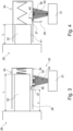
- the Fig. 3 and 4 show a wear detection system 29 with a transponder unit 30 and a transmitting-receiving unit 31 as well as a carbon brush 32.
- the carbon brush 32 is inserted into a holder 33, on the outer surface 34 of which the transponder unit 30 is firmly fixed.
- a shielding device 35 is formed from a cover element 36 made of metal, which is held on a wall 38 of the holder 33 so as to be pivotable about an axis 37.
- the cover element 36 is designed in the manner of a rocker with an outer end 39 for shielding the transponder unit 30 and an inner end 40 for contact with a side surface 41 of the carbon brush 32.
- the inner end 40 of the cover element 36 rests on the side surface 41 of the carbon brush 32 in such a way that the outer end 39 of the cover element 36 shields the transponder unit 30 against electromagnetic radiation or a signal 42 of the transmitting/receiving unit 31.
- the inner end 40 can no longer rest on the side surface 41, so that the cover element 36 is suddenly released due to a force not shown in detail here, for example by a spring or weight, so that it is pivoted about the axis 37 and the outer end 39 no longer shields the transponder unit 30.
- the signal 42 can now be received by the transponder unit 30, whereby the transponder unit 30 sends a signal 43 back to the transmitting/receiving unit 31.
- the transmitting/receiving unit 31 can now register an exceedance of a length l3 of the carbon brush 32 and, if necessary, forward it to a higher-level machine control.
Landscapes
- Engineering & Computer Science (AREA)
- General Engineering & Computer Science (AREA)
- Mechanical Engineering (AREA)
- Power Engineering (AREA)
- Microelectronics & Electronic Packaging (AREA)
- Braking Arrangements (AREA)
- Transplanting Machines (AREA)
- Motor Or Generator Current Collectors (AREA)
Claims (9)
- Système (29) pour la détection de l'usure, notamment pour des éléments de frottement, tels que des brosses, des garnitures de friction, des garnitures de frein, des pièces de lubrification ou similaires, comprenant au moins un élément de frottement consommable et une unité de transpondeur (30), dans lequel l'unité de transpondeur peut communiquer sans fil avec une unité d'émission-réception (31), dans lequel le système pour la détection de l'usure comprend un dispositif de blindage (35), ledit dispositif de blindage étant configuré de telle manière qu'au moyen du dispositif de blindage, l'unité de transpondeur peut être au moins partiellement blindée en fonction d'un état d'usure de l'élément de frottement, de telle manière que la communication entre l'unité de transpondeur and the unité émission-réception peut être influencée,
caractérisé en ce que
le système pour la détection de l'usure comprend une structure de support (33) qui sert à positionner de manière mobile l'élément de frottement par rapport à une surface de frottement, l'unité de transpondeur étant reliée de manière inamovible à la structure de support, le dispositif de blindage étant formé d'un élément de blindage (36), qui est disposé sur la structure de support et qui peut couvrir l'unité de transpondeur d'une manière blindée ou la découvrir lorsqu'un mouvement de l'élément de frottement par rapport à la structure de support se produit. - Système pour la détection de l'usure selon la revendication 1, caractérisé en ce que
l'unité de transpondeur (30) a un codage qui peut être reçu par l'unité émission-réception (31). - Système pour la détection de l'usure selon la revendication 1 ou la revendication 2,
caractérisé en ce que
l'unité de transpondeur (30) est une unité de transpondeur RFID. - Système pour la détection de l'usure selon l'une quelconque des revendications précédentes,
caractérisé en ce que
l'élément de frottement est une pièce de contact (32) pour transmettre l'énergie électrique. - Système pour la détection de l'usure selon l'une quelconque des revendications précédentes,
caractérisé en ce que
le dispositif de blindage (35) est disposé directement à côté de l'unité de transpondeur (30). - Procédé de détection de l'usure, notamment pour des éléments de frottement, tels que des brosses, des garnitures de friction, des garnitures de frein, des pièces de lubrification ou similaires, comprenant au moins un élément de frottement consommable, et comprenant une unité de transpondeur (30), dans lequel l'unité de transpondeur peut communiquer sans fil avec une unité émission-réception (31),
caractérisé en ce
qu'au moyen d'un dispositif de blindage (35), l'unité de transpondeur est au moins partiellement blindée en fonction d'un état de l'usure de l'élément de frottement de sorte que la communication entre l'unité de transpondeur et l'unité émission-réception est influencée, le système (29) pour la détection de l'usure comprenant une structure de support (33) qui sert à positionner de manière mobile l'élément de frottement par rapport à une surface de frottement (16), l'unité de transpondeur étant reliée de manière inamovible à la structure de support, le dispositif de blindage étant formé d'un élément de blindage (36), qui est disposé sur la structure de support et au moyen duquel l'unité de transpondeur est couverte de manière blindé ou est découverte lorsqu'un mouvement de l'élément de frottement par rapport à la structure de support se produit. - Procédé selon la revendication 6,
caractérisé en ce que
le dispositif de blindage (35) modifie une permittivité d'une plage de transmission spatiale de l'unité de transpondeur (30). - Procédé selon la revendication 6 ou la revendication 7, caractérisé en ce que
par la modification dimensionnel lié à l'usure de l'élément de frottement, un blindage ou une élimination d'un blindage de l'unité de transpondeur (30) se produit. - Procédé selon l'une quelconque des revendications 6 à 8, caractérisé en ce
qu'en fonction d'une position de l'unité de transpondeur (30) par rapport à une surface de frottement contactée par l'élément de frottement, un blindage ou une élimination d'un blindage de l'unité de transpondeur se produit.
Applications Claiming Priority (3)
| Application Number | Priority Date | Filing Date | Title |
|---|---|---|---|
| DE102011005302A DE102011005302B4 (de) | 2011-03-09 | 2011-03-09 | Verschleißerkennungssystem und Verfahren |
| PCT/EP2012/052291 WO2012119832A1 (fr) | 2011-03-09 | 2012-02-10 | Système et procédé de détection d'usure |
| EP12709810.1A EP2683561B1 (fr) | 2011-03-09 | 2012-02-10 | Système et procédé de détection d'usure |
Related Parent Applications (1)
| Application Number | Title | Priority Date | Filing Date |
|---|---|---|---|
| EP12709810.1A Division EP2683561B1 (fr) | 2011-03-09 | 2012-02-10 | Système et procédé de détection d'usure |
Publications (2)
| Publication Number | Publication Date |
|---|---|
| EP4046828A1 EP4046828A1 (fr) | 2022-08-24 |
| EP4046828B1 true EP4046828B1 (fr) | 2024-12-18 |
Family
ID=45872908
Family Applications (2)
| Application Number | Title | Priority Date | Filing Date |
|---|---|---|---|
| EP22162605.4A Active EP4046828B1 (fr) | 2011-03-09 | 2012-02-10 | Système et procédé de détection d'usure |
| EP12709810.1A Active EP2683561B1 (fr) | 2011-03-09 | 2012-02-10 | Système et procédé de détection d'usure |
Family Applications After (1)
| Application Number | Title | Priority Date | Filing Date |
|---|---|---|---|
| EP12709810.1A Active EP2683561B1 (fr) | 2011-03-09 | 2012-02-10 | Système et procédé de détection d'usure |
Country Status (8)
| Country | Link |
|---|---|
| US (1) | US20140091918A1 (fr) |
| EP (2) | EP4046828B1 (fr) |
| JP (1) | JP2014509823A (fr) |
| KR (1) | KR101536499B1 (fr) |
| CN (1) | CN103561972A (fr) |
| DE (1) | DE102011005302B4 (fr) |
| ES (1) | ES2917878T3 (fr) |
| WO (1) | WO2012119832A1 (fr) |
Families Citing this family (23)
| Publication number | Priority date | Publication date | Assignee | Title |
|---|---|---|---|---|
| JP6059931B2 (ja) * | 2012-09-24 | 2017-01-11 | 株式会社ディスコ | 切削装置 |
| US9252643B2 (en) | 2013-03-14 | 2016-02-02 | Cutsforth, Inc. | System and method for monitoring the status of one or more components of an electrical machine |
| DE102013014534B3 (de) * | 2013-09-03 | 2014-05-22 | Sew-Eurodrive Gmbh & Co Kg | Anordnung zur Verschleißerkennung, Bremse, Elektromotor mit Bremse und Verwendung eines RFID als Mittel zur Detektion des Bremsbelagverschleisses |
| WO2015160656A1 (fr) * | 2014-04-16 | 2015-10-22 | Flsmidth A/S | Procédés et appareil de surveillance continue de l'usure dans des circuits de flottation |
| US9762015B2 (en) * | 2014-06-10 | 2017-09-12 | General Electric Company | Brush holder apparatus and system |
| DE102014017895A1 (de) * | 2014-12-03 | 2016-06-09 | Dürr Systems GmbH | Applikationsanlagenbauteil mit Transponder und/oder Verschleißerkennungseinrichtung |
| US10189098B2 (en) * | 2015-03-12 | 2019-01-29 | Robert Bosch Tool Corporation | Diagnostic and maintenance operation for a saw |
| WO2016196484A1 (fr) | 2015-06-01 | 2016-12-08 | Cutsforth, Inc. | Surveillance de l'usure et des vibrations d'un balai |
| CN105337134B (zh) * | 2015-12-01 | 2017-12-01 | 南京钢铁股份有限公司 | 一种可查看寿命的直流电机碳刷 |
| CN105403417B (zh) * | 2015-12-15 | 2017-09-29 | 长春轨道客车股份有限公司 | 轨道车辆轴端接地装置磨损试验台 |
| AU2017206696A1 (en) | 2016-01-11 | 2018-07-05 | Cutsforth, Inc. | Monitoring system for grounding apparatus |
| US20170307036A1 (en) * | 2016-04-20 | 2017-10-26 | GM Global Technology Operations LLC | Brake telemetry systems and methods |
| DE102016116998B8 (de) * | 2016-09-09 | 2018-05-17 | Saf-Holland Gmbh | Verschleißsensierung |
| WO2018071569A1 (fr) * | 2016-10-12 | 2018-04-19 | Rei, Inc. | Procédé et système de surveillance d'usure à l'aide de réflexions de rf |
| DE102017115744A1 (de) * | 2017-07-13 | 2019-01-17 | Conductix-Wampfler Gmbh | Vorrichtung und Verfahren zur Erkennung des Verschleißes eines Schleifkontaktes und Schleifleitungssystem |
| JP6886369B2 (ja) * | 2017-08-29 | 2021-06-16 | 川崎重工業株式会社 | 鉄道車両の制輪子摩耗検知ユニット及びそのセット |
| GB2567888B (en) * | 2017-10-31 | 2020-09-30 | Schrader Electronics Ltd | Tire sensor location method and apparatus |
| CA3114764A1 (fr) | 2018-10-04 | 2020-04-09 | Cutsforth, Inc. | Systeme et procede de surveillance de l'etat d'un ou de plusieurs composants d'une machine electrique |
| EP3861605A1 (fr) | 2018-10-04 | 2021-08-11 | Cutsforth, Inc. | Système et procédé pour surveiller l'état d'un ou plusieurs composant(s) d'une machine électrique |
| EP3734776A1 (fr) | 2019-05-02 | 2020-11-04 | Siemens Gamesa Renewable Energy A/S | Agencement de surveillance de l'usure de brosses et méthode associée |
| CN111307202A (zh) * | 2019-11-19 | 2020-06-19 | 辽宁红德电碳制品有限公司 | 一种电刷材料性能检测装置 |
| FR3103597B1 (fr) * | 2019-11-21 | 2023-10-13 | St Microelectronics Rousset | Procédé de contrôle du positionnement relatif de deux objets et système correspondant |
| KR102755421B1 (ko) | 2022-01-04 | 2025-01-14 | 한전케이피에스 주식회사 | 브러시 점검용 측정장치 |
Family Cites Families (20)
| Publication number | Priority date | Publication date | Assignee | Title |
|---|---|---|---|---|
| JPS5747871U (fr) * | 1980-09-03 | 1982-03-17 | ||
| GB2092390A (en) * | 1981-01-30 | 1982-08-11 | Sbw Engineers Ltd | Detecting component wear |
| JPS59106857A (ja) * | 1982-12-07 | 1984-06-20 | Mitsubishi Electric Corp | ブラシ摩耗検出装置 |
| JPS59106856A (ja) * | 1982-12-07 | 1984-06-20 | Mitsubishi Electric Corp | ブラシ摩耗検出装置 |
| DE3247330A1 (de) * | 1982-12-21 | 1984-06-28 | Brown, Boveri & Cie Ag, 6800 Mannheim | Vorrichtung zur ueberwachung der buerstenabnutzung |
| DE4242861A1 (de) * | 1992-12-18 | 1994-06-23 | Diehl Gmbh & Co | Einrichtung zum Erfassen des Reifendruckes eines Kraftfahrzeugrades |
| US5525796A (en) * | 1994-06-22 | 1996-06-11 | Mcdonnell Douglas Corporation | Fiber optic sensing apparatus for detecting a fracture in a metallic workpiece and an associated method of attaching a fiber optic sensing element to the metallic workpiece |
| DE19840081B4 (de) * | 1998-09-03 | 2004-08-05 | Contitech Transportbandsysteme Gmbh | System und Verfahren zur Überwachung einer einem Verschleiß unterworfenen Schicht eines Gegenstandes, insbesondere der Deckschicht eines Fördergurtes |
| CN2566050Y (zh) * | 2002-08-01 | 2003-08-13 | 司国庆 | 汽车制动磨损报警器 |
| DE10348884A1 (de) * | 2003-10-14 | 2005-05-25 | Pilz Gmbh & Co. Kg | Sicherheitsschalter, insbesondere Not-Aus-Schalter, zum sicheren Abschalten eines gefahrbringenden Gerätes |
| DE102004001799B4 (de) * | 2004-01-05 | 2008-12-11 | Pantrac Gmbh | Sensoreinrichtung zur Signalisierung von Verschleisszuständen an Schleifkörpern |
| DE102004049024B3 (de) * | 2004-09-20 | 2006-04-13 | K.A. Schmersal Holding Kg | Positionsüberwachungseinrichtung |
| NO20051398D0 (no) * | 2005-03-14 | 2005-03-14 | Terje Donvold | System for kontroll, maling og fjernovervaking av stoff i fast-, vaeske- eller gassform i stillstand eller bevegelse |
| JP4932222B2 (ja) * | 2005-04-13 | 2012-05-16 | 株式会社ブリヂストン | コンベヤベルトの摩耗検出装置 |
| JP2007300745A (ja) * | 2006-05-01 | 2007-11-15 | Meidensha Corp | パンタグラフすり板の磨耗検知装置 |
| DE102007009423B4 (de) | 2007-02-23 | 2012-03-22 | Schunk Kohlenstofftechnik Gmbh | Vorrichtung mit einem elektrischen Kontaktelement sowie ein solches |
| DE102008032818A1 (de) * | 2007-10-10 | 2009-04-16 | Continental Teves Ag & Co. Ohg | Bremsbacke |
| DE202008002298U1 (de) * | 2008-02-19 | 2008-04-10 | Data-Complex Gmbh | Vorrichtungen und System zum Aktivieren und Deaktivieren mindestens eines Transponders |
| EP2112518A1 (fr) * | 2008-04-25 | 2009-10-28 | ALSTOM Technology Ltd | Moniteur d'usure de brosse |
| US8384266B2 (en) * | 2011-03-29 | 2013-02-26 | General Electric Company | Brush wear detector system with wireless sensor |
-
2011
- 2011-03-09 DE DE102011005302A patent/DE102011005302B4/de active Active
-
2012
- 2012-02-10 US US14/003,580 patent/US20140091918A1/en not_active Abandoned
- 2012-02-10 JP JP2013557025A patent/JP2014509823A/ja active Pending
- 2012-02-10 EP EP22162605.4A patent/EP4046828B1/fr active Active
- 2012-02-10 EP EP12709810.1A patent/EP2683561B1/fr active Active
- 2012-02-10 CN CN201280012464.3A patent/CN103561972A/zh active Pending
- 2012-02-10 WO PCT/EP2012/052291 patent/WO2012119832A1/fr not_active Ceased
- 2012-02-10 ES ES12709810T patent/ES2917878T3/es active Active
- 2012-02-10 KR KR1020137026110A patent/KR101536499B1/ko not_active Expired - Fee Related
Also Published As
| Publication number | Publication date |
|---|---|
| CN103561972A (zh) | 2014-02-05 |
| US20140091918A1 (en) | 2014-04-03 |
| KR20140013018A (ko) | 2014-02-04 |
| WO2012119832A1 (fr) | 2012-09-13 |
| JP2014509823A (ja) | 2014-04-21 |
| EP4046828A1 (fr) | 2022-08-24 |
| ES2917878T3 (es) | 2022-07-12 |
| DE102011005302A1 (de) | 2012-09-13 |
| KR101536499B1 (ko) | 2015-07-13 |
| EP2683561A1 (fr) | 2014-01-15 |
| DE102011005302B4 (de) | 2012-10-31 |
| EP2683561B1 (fr) | 2022-04-06 |
Similar Documents
| Publication | Publication Date | Title |
|---|---|---|
| EP4046828B1 (fr) | Système et procédé de détection d'usure | |
| EP3191733B1 (fr) | Mâchoire de frein avec indicateur d'usure | |
| DE102011084229A1 (de) | Temperatursensor mit integriertem Toleranzausgleich und Haltekraft | |
| EP2630386B2 (fr) | Indicateur d'usure de garniture de frein, frein à disque muni d'un tel indicateur et segments de frein pour de tels freins à disque | |
| EP3064694B1 (fr) | Alimentation en courant pour un battant de porte ou de fenetre | |
| EP2423068A1 (fr) | Contact de mise à la terre | |
| DE102015006345A1 (de) | Elektrische Maschine mit Temperatursensor | |
| EP3309967B1 (fr) | Dispositif de commutation capacitif | |
| EP3264426B1 (fr) | Cable electrique blinde et sa methode de fabrication | |
| DE102018128178A1 (de) | Elektrische Maschine mit integriertem Temperatursensor und Rotorzustandserfassungssensor | |
| DE102012012474A1 (de) | Scheibenbremsenanordnung mit elektrischer Belagverschleissnachstellvorrichtung und Drehzahlsensor | |
| DE102014211427A1 (de) | Sensoraufnahme für einen hydraulischen Zylinder und Verfahren zum Fixieren eines Sensors | |
| DE102015206800A1 (de) | Elektrischer Zentralausrücker mit in Träger gehaltertem Stecker und Hybridmodul mit solchem Aktor | |
| DE102014216207B4 (de) | Bremsvorrichtung | |
| DE102008062779A1 (de) | Detektionsvorrichtung und Verfahren zur Temperaturmessung | |
| EP2458693B1 (fr) | Unité de bague collectrice | |
| EP4204699B1 (fr) | Element de palier doté d'un capteur et d'un dispositif de telemetrie | |
| DE102018128176A1 (de) | Elektrische Maschine mit inhärentem Rotorlagesensor mit integriertem Temperatursensor | |
| DE10260070B4 (de) | System mit einem elektrischen Kabel | |
| DE102020110311A1 (de) | Vorrichtung zur Überwachung eines Bauteils | |
| WO2008034890A2 (fr) | Dispositif de détection d'une force et/ou d'un couple | |
| DE102015206096A1 (de) | Geschirmtes Kabel mit Beilaufleiter | |
| DE102017216924A1 (de) | Aktuator, Getriebe sowie Kraftfahrzeug | |
| DE102010045468A1 (de) | Anordnung zur Bestimmung von Verdrehungen von lang gestreckten Körpern |
Legal Events
| Date | Code | Title | Description |
|---|---|---|---|
| PUAI | Public reference made under article 153(3) epc to a published international application that has entered the european phase |
Free format text: ORIGINAL CODE: 0009012 |
|
| STAA | Information on the status of an ep patent application or granted ep patent |
Free format text: STATUS: THE APPLICATION HAS BEEN PUBLISHED |
|
| AC | Divisional application: reference to earlier application |
Ref document number: 2683561 Country of ref document: EP Kind code of ref document: P |
|
| AK | Designated contracting states |
Kind code of ref document: A1 Designated state(s): AL AT BE BG CH CY CZ DE DK EE ES FI FR GB GR HR HU IE IS IT LI LT LU LV MC MK MT NL NO PL PT RO RS SE SI SK SM TR |
|
| STAA | Information on the status of an ep patent application or granted ep patent |
Free format text: STATUS: REQUEST FOR EXAMINATION WAS MADE |
|
| 17P | Request for examination filed |
Effective date: 20230112 |
|
| RBV | Designated contracting states (corrected) |
Designated state(s): AL AT BE BG CH CY CZ DE DK EE ES FI FR GB GR HR HU IE IS IT LI LT LU LV MC MK MT NL NO PL PT RO RS SE SI SK SM TR |
|
| GRAP | Despatch of communication of intention to grant a patent |
Free format text: ORIGINAL CODE: EPIDOSNIGR1 |
|
| STAA | Information on the status of an ep patent application or granted ep patent |
Free format text: STATUS: GRANT OF PATENT IS INTENDED |
|
| RIC1 | Information provided on ipc code assigned before grant |
Ipc: H01R 39/58 20060101ALI20240612BHEP Ipc: F16D 66/02 20060101ALI20240612BHEP Ipc: B60C 11/24 20060101AFI20240612BHEP |
|
| INTG | Intention to grant announced |
Effective date: 20240710 |
|
| GRAS | Grant fee paid |
Free format text: ORIGINAL CODE: EPIDOSNIGR3 |
|
| GRAA | (expected) grant |
Free format text: ORIGINAL CODE: 0009210 |
|
| STAA | Information on the status of an ep patent application or granted ep patent |
Free format text: STATUS: THE PATENT HAS BEEN GRANTED |
|
| AC | Divisional application: reference to earlier application |
Ref document number: 2683561 Country of ref document: EP Kind code of ref document: P |
|
| AK | Designated contracting states |
Kind code of ref document: B1 Designated state(s): AL AT BE BG CH CY CZ DE DK EE ES FI FR GB GR HR HU IE IS IT LI LT LU LV MC MK MT NL NO PL PT RO RS SE SI SK SM TR |
|
| REG | Reference to a national code |
Ref country code: CH Ref legal event code: EP |
|
| REG | Reference to a national code |
Ref country code: DE Ref legal event code: R096 Ref document number: 502012017288 Country of ref document: DE |
|
| REG | Reference to a national code |
Ref country code: IE Ref legal event code: FG4D Free format text: LANGUAGE OF EP DOCUMENT: GERMAN |
|
| REG | Reference to a national code |
Ref country code: LT Ref legal event code: MG9D |
|
| PG25 | Lapsed in a contracting state [announced via postgrant information from national office to epo] |
Ref country code: HR Free format text: LAPSE BECAUSE OF FAILURE TO SUBMIT A TRANSLATION OF THE DESCRIPTION OR TO PAY THE FEE WITHIN THE PRESCRIBED TIME-LIMIT Effective date: 20241218 |
|
| PG25 | Lapsed in a contracting state [announced via postgrant information from national office to epo] |
Ref country code: FI Free format text: LAPSE BECAUSE OF FAILURE TO SUBMIT A TRANSLATION OF THE DESCRIPTION OR TO PAY THE FEE WITHIN THE PRESCRIBED TIME-LIMIT Effective date: 20241218 |
|
| PG25 | Lapsed in a contracting state [announced via postgrant information from national office to epo] |
Ref country code: BG Free format text: LAPSE BECAUSE OF FAILURE TO SUBMIT A TRANSLATION OF THE DESCRIPTION OR TO PAY THE FEE WITHIN THE PRESCRIBED TIME-LIMIT Effective date: 20241218 |
|
| PG25 | Lapsed in a contracting state [announced via postgrant information from national office to epo] |
Ref country code: NO Free format text: LAPSE BECAUSE OF FAILURE TO SUBMIT A TRANSLATION OF THE DESCRIPTION OR TO PAY THE FEE WITHIN THE PRESCRIBED TIME-LIMIT Effective date: 20250318 |
|
| REG | Reference to a national code |
Ref country code: NL Ref legal event code: MP Effective date: 20241218 |
|
| PG25 | Lapsed in a contracting state [announced via postgrant information from national office to epo] |
Ref country code: LV Free format text: LAPSE BECAUSE OF FAILURE TO SUBMIT A TRANSLATION OF THE DESCRIPTION OR TO PAY THE FEE WITHIN THE PRESCRIBED TIME-LIMIT Effective date: 20241218 Ref country code: GR Free format text: LAPSE BECAUSE OF FAILURE TO SUBMIT A TRANSLATION OF THE DESCRIPTION OR TO PAY THE FEE WITHIN THE PRESCRIBED TIME-LIMIT Effective date: 20250319 |
|
| PG25 | Lapsed in a contracting state [announced via postgrant information from national office to epo] |
Ref country code: RS Free format text: LAPSE BECAUSE OF FAILURE TO SUBMIT A TRANSLATION OF THE DESCRIPTION OR TO PAY THE FEE WITHIN THE PRESCRIBED TIME-LIMIT Effective date: 20250318 |
|
| PG25 | Lapsed in a contracting state [announced via postgrant information from national office to epo] |
Ref country code: NL Free format text: LAPSE BECAUSE OF FAILURE TO SUBMIT A TRANSLATION OF THE DESCRIPTION OR TO PAY THE FEE WITHIN THE PRESCRIBED TIME-LIMIT Effective date: 20241218 |
|
| PG25 | Lapsed in a contracting state [announced via postgrant information from national office to epo] |
Ref country code: SM Free format text: LAPSE BECAUSE OF FAILURE TO SUBMIT A TRANSLATION OF THE DESCRIPTION OR TO PAY THE FEE WITHIN THE PRESCRIBED TIME-LIMIT Effective date: 20241218 |
|
| PG25 | Lapsed in a contracting state [announced via postgrant information from national office to epo] |
Ref country code: PL Free format text: LAPSE BECAUSE OF FAILURE TO SUBMIT A TRANSLATION OF THE DESCRIPTION OR TO PAY THE FEE WITHIN THE PRESCRIBED TIME-LIMIT Effective date: 20241218 |
|
| PG25 | Lapsed in a contracting state [announced via postgrant information from national office to epo] |
Ref country code: ES Free format text: LAPSE BECAUSE OF FAILURE TO SUBMIT A TRANSLATION OF THE DESCRIPTION OR TO PAY THE FEE WITHIN THE PRESCRIBED TIME-LIMIT Effective date: 20241218 |
|
| PG25 | Lapsed in a contracting state [announced via postgrant information from national office to epo] |
Ref country code: IS Free format text: LAPSE BECAUSE OF FAILURE TO SUBMIT A TRANSLATION OF THE DESCRIPTION OR TO PAY THE FEE WITHIN THE PRESCRIBED TIME-LIMIT Effective date: 20250418 |
|
| PG25 | Lapsed in a contracting state [announced via postgrant information from national office to epo] |
Ref country code: PT Free format text: LAPSE BECAUSE OF FAILURE TO SUBMIT A TRANSLATION OF THE DESCRIPTION OR TO PAY THE FEE WITHIN THE PRESCRIBED TIME-LIMIT Effective date: 20250421 |
|
| PG25 | Lapsed in a contracting state [announced via postgrant information from national office to epo] |
Ref country code: EE Free format text: LAPSE BECAUSE OF FAILURE TO SUBMIT A TRANSLATION OF THE DESCRIPTION OR TO PAY THE FEE WITHIN THE PRESCRIBED TIME-LIMIT Effective date: 20241218 |
|
| PG25 | Lapsed in a contracting state [announced via postgrant information from national office to epo] |
Ref country code: RO Free format text: LAPSE BECAUSE OF FAILURE TO SUBMIT A TRANSLATION OF THE DESCRIPTION OR TO PAY THE FEE WITHIN THE PRESCRIBED TIME-LIMIT Effective date: 20241218 |
|
| PG25 | Lapsed in a contracting state [announced via postgrant information from national office to epo] |
Ref country code: SK Free format text: LAPSE BECAUSE OF FAILURE TO SUBMIT A TRANSLATION OF THE DESCRIPTION OR TO PAY THE FEE WITHIN THE PRESCRIBED TIME-LIMIT Effective date: 20241218 |
|
| PG25 | Lapsed in a contracting state [announced via postgrant information from national office to epo] |
Ref country code: CZ Free format text: LAPSE BECAUSE OF FAILURE TO SUBMIT A TRANSLATION OF THE DESCRIPTION OR TO PAY THE FEE WITHIN THE PRESCRIBED TIME-LIMIT Effective date: 20241218 |
|
| PG25 | Lapsed in a contracting state [announced via postgrant information from national office to epo] |
Ref country code: IT Free format text: LAPSE BECAUSE OF FAILURE TO SUBMIT A TRANSLATION OF THE DESCRIPTION OR TO PAY THE FEE WITHIN THE PRESCRIBED TIME-LIMIT Effective date: 20241218 |
|
| REG | Reference to a national code |
Ref country code: DE Ref legal event code: R119 Ref document number: 502012017288 Country of ref document: DE |
|
| PG25 | Lapsed in a contracting state [announced via postgrant information from national office to epo] |
Ref country code: SE Free format text: LAPSE BECAUSE OF FAILURE TO SUBMIT A TRANSLATION OF THE DESCRIPTION OR TO PAY THE FEE WITHIN THE PRESCRIBED TIME-LIMIT Effective date: 20241218 |
|
| PG25 | Lapsed in a contracting state [announced via postgrant information from national office to epo] |
Ref country code: MC Free format text: LAPSE BECAUSE OF FAILURE TO SUBMIT A TRANSLATION OF THE DESCRIPTION OR TO PAY THE FEE WITHIN THE PRESCRIBED TIME-LIMIT Effective date: 20241218 |
|
| REG | Reference to a national code |
Ref country code: CH Ref legal event code: PL |
|
| PG25 | Lapsed in a contracting state [announced via postgrant information from national office to epo] |
Ref country code: DK Free format text: LAPSE BECAUSE OF FAILURE TO SUBMIT A TRANSLATION OF THE DESCRIPTION OR TO PAY THE FEE WITHIN THE PRESCRIBED TIME-LIMIT Effective date: 20241218 |
|
| PG25 | Lapsed in a contracting state [announced via postgrant information from national office to epo] |
Ref country code: LU Free format text: LAPSE BECAUSE OF NON-PAYMENT OF DUE FEES Effective date: 20250210 |
|
| PG25 | Lapsed in a contracting state [announced via postgrant information from national office to epo] |
Ref country code: CH Free format text: LAPSE BECAUSE OF NON-PAYMENT OF DUE FEES Effective date: 20250228 |
|
| PLBE | No opposition filed within time limit |
Free format text: ORIGINAL CODE: 0009261 |
|
| STAA | Information on the status of an ep patent application or granted ep patent |
Free format text: STATUS: NO OPPOSITION FILED WITHIN TIME LIMIT |
|
| 26N | No opposition filed |
Effective date: 20250919 |
|
| GBPC | Gb: european patent ceased through non-payment of renewal fee |
Effective date: 20250318 |
|
| REG | Reference to a national code |
Ref country code: BE Ref legal event code: MM Effective date: 20250228 |
|
| PG25 | Lapsed in a contracting state [announced via postgrant information from national office to epo] |
Ref country code: DE Free format text: LAPSE BECAUSE OF NON-PAYMENT OF DUE FEES Effective date: 20250902 |
|
| PG25 | Lapsed in a contracting state [announced via postgrant information from national office to epo] |
Ref country code: GB Free format text: LAPSE BECAUSE OF NON-PAYMENT OF DUE FEES Effective date: 20250318 |
|
| PG25 | Lapsed in a contracting state [announced via postgrant information from national office to epo] |
Ref country code: FR Free format text: LAPSE BECAUSE OF NON-PAYMENT OF DUE FEES Effective date: 20250218 |
|
| PG25 | Lapsed in a contracting state [announced via postgrant information from national office to epo] |
Ref country code: BE Free format text: LAPSE BECAUSE OF NON-PAYMENT OF DUE FEES Effective date: 20250228 |
|
| PG25 | Lapsed in a contracting state [announced via postgrant information from national office to epo] |
Ref country code: IE Free format text: LAPSE BECAUSE OF NON-PAYMENT OF DUE FEES Effective date: 20250210 |