EP4046828B1 - Wear detection system and method - Google Patents
Wear detection system and method Download PDFInfo
- Publication number
- EP4046828B1 EP4046828B1 EP22162605.4A EP22162605A EP4046828B1 EP 4046828 B1 EP4046828 B1 EP 4046828B1 EP 22162605 A EP22162605 A EP 22162605A EP 4046828 B1 EP4046828 B1 EP 4046828B1
- Authority
- EP
- European Patent Office
- Prior art keywords
- transponder unit
- shielding
- unit
- friction
- friction element
- Prior art date
- Legal status (The legal status is an assumption and is not a legal conclusion. Google has not performed a legal analysis and makes no representation as to the accuracy of the status listed.)
- Active
Links
Images

Classifications
-
- F—MECHANICAL ENGINEERING; LIGHTING; HEATING; WEAPONS; BLASTING
- F16—ENGINEERING ELEMENTS AND UNITS; GENERAL MEASURES FOR PRODUCING AND MAINTAINING EFFECTIVE FUNCTIONING OF MACHINES OR INSTALLATIONS; THERMAL INSULATION IN GENERAL
- F16D—COUPLINGS FOR TRANSMITTING ROTATION; CLUTCHES; BRAKES
- F16D66/00—Arrangements for monitoring working conditions, e.g. wear, temperature
- F16D66/02—Apparatus for indicating wear
- F16D66/021—Apparatus for indicating wear using electrical detection or indication means
-
- B—PERFORMING OPERATIONS; TRANSPORTING
- B60—VEHICLES IN GENERAL
- B60C—VEHICLE TYRES; TYRE INFLATION; TYRE CHANGING; CONNECTING VALVES TO INFLATABLE ELASTIC BODIES IN GENERAL; DEVICES OR ARRANGEMENTS RELATED TO TYRES
- B60C11/00—Tyre tread bands; Tread patterns; Anti-skid inserts
- B60C11/24—Wear-indicating arrangements
- B60C11/246—Tread wear monitoring systems
-
- F—MECHANICAL ENGINEERING; LIGHTING; HEATING; WEAPONS; BLASTING
- F16—ENGINEERING ELEMENTS AND UNITS; GENERAL MEASURES FOR PRODUCING AND MAINTAINING EFFECTIVE FUNCTIONING OF MACHINES OR INSTALLATIONS; THERMAL INSULATION IN GENERAL
- F16D—COUPLINGS FOR TRANSMITTING ROTATION; CLUTCHES; BRAKES
- F16D66/00—Arrangements for monitoring working conditions, e.g. wear, temperature
- F16D66/02—Apparatus for indicating wear
- F16D66/021—Apparatus for indicating wear using electrical detection or indication means
- F16D66/026—Apparatus for indicating wear using electrical detection or indication means indicating different degrees of lining wear
-
- H—ELECTRICITY
- H01—ELECTRIC ELEMENTS
- H01R—ELECTRICALLY-CONDUCTIVE CONNECTIONS; STRUCTURAL ASSOCIATIONS OF A PLURALITY OF MUTUALLY-INSULATED ELECTRICAL CONNECTING ELEMENTS; COUPLING DEVICES; CURRENT COLLECTORS
- H01R39/00—Rotary current collectors, distributors or interrupters
- H01R39/02—Details for dynamo electric machines
- H01R39/58—Means structurally associated with the current collector for indicating condition thereof, e.g. for indicating brush wear
-
- H—ELECTRICITY
- H02—GENERATION; CONVERSION OR DISTRIBUTION OF ELECTRIC POWER
- H02K—DYNAMO-ELECTRIC MACHINES
- H02K11/00—Structural association of dynamo-electric machines with electric components or with devices for shielding, monitoring or protection
- H02K11/20—Structural association of dynamo-electric machines with electric components or with devices for shielding, monitoring or protection for measuring, monitoring, testing, protecting or switching
-
- H—ELECTRICITY
- H02—GENERATION; CONVERSION OR DISTRIBUTION OF ELECTRIC POWER
- H02K—DYNAMO-ELECTRIC MACHINES
- H02K5/00—Casings; Enclosures; Supports
- H02K5/04—Casings or enclosures characterised by the shape, form or construction thereof
- H02K5/14—Means for supporting or protecting brushes or brush holders
Definitions
- the invention relates to a wear detection system and a method for wear detection, in particular for friction elements such as brushes, friction linings, brake linings, lubricating pieces or the like, with at least one consumable friction element and a transponder unit, wherein the transponder unit can communicate wirelessly with a transmitting-receiving unit.
- Friction elements such as carbon brushes for electric motors, friction linings for power transmission, brake linings and solid lubricant pieces, are always subject to wear due to abrasion of the friction element material. It is often desirable to replace the friction element before it reaches a wear limit that impairs its function. Wear detection systems are therefore regularly used to monitor the wear status of friction elements. Electrical contacts on friction elements or switches that can signal when a wear limit is reached are well known here. However, such wear detection systems require wiring of the Contacts or switches with a control unit. Such wiring is relatively expensive to produce, especially if a large number of friction elements are to be monitored simultaneously. For example, wiring for brushes on a generator can be designed in a series circuit to reduce the wiring effort. However, the wear detection system can then no longer identify which brush triggered the signal in question.
- the known wear detection system has the disadvantage that the transponder unit must be destroyed when the wear limit is reached.
- the transponder unit must therefore be designed or attached to the carbon brush in such a way that it is reliably destroyed when the wear limit or the friction surface is reached.
- Inexpensive transponder units such as those available in label form, cannot therefore be used here, as the labels can come off due to heat in the immediate vicinity of the friction surface or cannot be mechanically destroyed due to poor adhesion to the carbon brush.
- transponder unit is additionally equipped with measuring sensors.
- the transponder unit can be attached to a friction element in any position that is suitable for installation, with the transponder unit being connected, for example, via a cable to a measuring sensor or a simple contact attached in the area of a wear limit of the friction element.
- Transponder units that need to be destroyed are therefore difficult to attach, and those that are equipped with measuring sensors and connecting cables are comparatively expensive.
- the present invention is therefore based on the object of proposing a wear detection system and a method for wear detection, which enables cost-effective and simple wear monitoring of friction elements.
- the wear detection system in particular for friction elements such as brushes, friction linings, brake linings, lubricating pieces or the like, comprises at least one consumable friction element and a transponder unit, wherein the transponder unit can communicate wirelessly with a transmitting-receiving unit, wherein the wear detection system has a shielding device, wherein the shielding device is designed such that the transponder unit can be at least partially shielded by means of the shielding device depending on a wear state of the friction element, such that communication between the transponder unit and the transmitting-receiving unit can be influenced, wherein the wear detection system comprises a holding device which is used for the movable positioning of the friction element relative to a friction surface serves, wherein the transponder unit is fixedly connected to the holding device, wherein the shielding device is designed as a shielding element arranged on the holding device, which can cover or uncover the transponder unit when a movement of the friction element occurs relative to the holding device.
- the transponder unit By influencing the transponder unit with an independently designed shielding device, it is possible to change, prevent or even enable a communication connection between the transponder unit and the transmitting/receiving unit. Since the signal received by the transponder unit from the transmitting/receiving unit is essentially influenced solely by the shielding device, almost any transponder unit, in particular a cost-effective transponder unit, can be used as a transponder unit. Furthermore, communication between the transponder unit and the transmitting/receiving unit is made significantly easier, since the content of the transmitted data is fundamentally irrelevant. It only matters that the transponder unit is detected or recognized by the transmitting/receiving unit.
- the transmission/reception unit can detect that the friction element has reached its wear limit by changing the response signal from the transponder unit or, alternatively, by the transponder signal not being received after it had previously been received or by a transponder signal not being received after it had previously been received.
- the wear detection system comprises a holding device which serves for the movable positioning of the friction element relative to a friction surface and for contacting the friction element with the friction surface.
- the friction element can therefore be held or received by the holding device and pressed against a friction surface with a pressing force, for example by means of a spring device or an actuator.
- the friction element can be monolithic with a cuboid shape or rod-shaped and can be received by the holding device in such a way that it can be moved essentially orthogonally to the friction surface in the holding device.
- the reduction in length and longitudinal movement of the friction element relative to the holding device caused by wear of the friction element can then influence the communication between the transponder unit and the transceiver unit by means of the shielding device.
- the transponder unit is connected in a fixed position to the holding device, wherein the shielding device is designed as a shielding element arranged on the holding device, which covers the transponder unit in a shielding manner or releases it when the friction element moves relative to the holding device.
- the transponder unit can, for example, be attached directly to a surface of the holding device without the transponder unit being in contact with the friction element.
- the shielding device is designed as a shielding element which, depending on a change in the length of the friction element, covers the transponder unit in a shielding manner or releases it for communication with the transceiver unit.
- the shielding element can, for example, be designed as a simple metal sheet which is moved relative to the transponder unit after one end of the friction element has passed through.
- a shielding device can also be designed inexpensively and enables particularly secure transmission or communication between the transponder unit and the transmitting/receiving unit, because the transponder unit is not exposed to high temperatures or vibrations due to the separation from the friction element.
- the holding device is made of a plastic material, a resonance frequency of, for example, an RFID transponder unit is then hardly influenced by surrounding materials with the exception of the shielding element.
- the transponder unit can have a code that can be received by the transceiver unit.
- the code can be used as a switching signal, for example to be able to start a machine. If a friction element is installed in the machine that does not have a predetermined code, a corresponding switching signal cannot be generated, so that as a result the machine cannot be started. This ensures that only friction elements approved for the machine can be used. If a large number of friction elements are used, it is also possible to determine which of the friction elements has failed or is worn if each friction element has an individual code using the transponder unit.
- the wear detection system can be connected to a control unit or a machine control system for such control purposes.
- the transponder unit can advantageously be an RFID transponder unit. It is also conceivable to use a transponder unit based on optical transmission technology, for example, but RFID transponder units are comparatively inexpensive and are also available in the form of an adhesive label. Passive RFID transponder units can preferably be used, as they do not require an external power supply. Furthermore, a radio signal between the RFID transponder unit and the transmitter-receiver unit can be easily influenced using the shielding device. In this way, a resonance frequency an antenna of the RFID transponder unit can easily be influenced by covering the antenna or by an electrical conductor near the antenna so that the radio signal is strongly attenuated or completely shielded.
- the friction element can be, for example, a contact piece for transmitting electrical energy, such as a carbon brush for an electric motor or generator.
- the wear detection system can be used effectively in particular when an electric motor has a large number of carbon brushes that have to be replaced regularly due to wear or damage. Such a wear detection system can be used particularly advantageously when the carbon brushes cannot be easily maintained, such as in a wind turbine. In principle, however, the wear detection system can also be used for other types of friction elements, such as all types of friction linings, brake linings or dry lubricants.
- Controlled shielding of the transponder unit can be made possible by arranging the shielding device directly adjacent to the transponder unit. If the transponder unit has an antenna, this can be directly shielded by a material that interacts with electromagnetic radiation, such as a metal material.
- the material or the shielding device formed from it always completely covers the transponder unit, whereby a permittivity of the shielding device is then formed unevenly relative to the transponder unit, so that communication with the transmitting-receiving unit is possible at least in one position of the transponder unit relative to the shielding device, or when the shielding device is completely or partially removed.
- the direct arrangement of the shielding device near the transponder unit allows a change in the position of the friction element relative to the shielding device. and/or to the transponder unit through communication between the transponder unit and the transmitting-receiving unit.
- the transponder unit can communicate wirelessly with a transmitting/receiving unit, wherein the transponder unit is at least partially shielded by means of a shielding device depending on a state of wear of the friction element, such that communication between the transponder unit and the transmitting/receiving unit is influenced, wherein the wear detection system comprises a holding device by means of which a movable positioning of the friction element takes place relative to a friction surface, wherein the transponder unit is connected in a fixed position to the holding device, wherein the shielding device is designed as a shielding element arranged on the holding device, by means of which the transponder unit is shielded or released when a movement of the friction element takes place relative to the holding device.
- the wear detection system comprises a holding device by means of which a movable positioning of the friction element takes place relative to a friction surface, wherein the transponder unit is connected in a fixed position to the holding device, wherein the shielding device is designed as a shielding element arranged on the
- a change in the length of the friction element caused by wear can thus cause a change in the position of the transponder unit relative to the shielding device.
- the method can be carried out particularly simply if the shielding device changes a permittivity of a spatial transmission area of the transponder unit.
- the shielding device can be arranged in the space between the transponder unit and the transmitting-receiving unit, which is used to transmit transmit or receive signals, and the transmit or receive signals can be changed by changing the permittivity of the relevant space. In electromagnetic transmission processes, this can be done, for example, by introducing electrically conductive materials into the space or removing them accordingly. If this happens depending on the wear condition of the friction element, a change in the permittivity can be used to infer a wear condition.
- Wear of the friction element caused by abrasion is accompanied by a dimensional change of the same, whereby the dimensional change, such as a change in length or abrasion of a surface, can result in the transponder unit being shielded or, alternatively, the shielding of the transponder unit being removed. Wear of the friction element is thus accompanied by a change in a received signal of the transponder unit, which can be detected by the transmitting/receiving unit and from which conclusions can be drawn about the state of wear of the friction element.
- Fig. 1 shows a schematic representation of a wear detection system 10 with a transponder unit 11, a transmitting-receiving unit 12 and a carbon brush 13.
- the carbon brush 13 is inserted into a holder 14 for longitudinally movable accommodation of the carbon brush 13 and is pressed by a spring 15 against a friction surface 16 of a slip ring 17 shown here in sections.
- the transponder unit 11 is glued to a rear end 18 of the carbon brush 13 on a side surface 19 of the carbon brush 13. Openings 20, 21 and 22 are formed in the holder 14, which is made of a metallic material, with which the transponder unit 11 can be covered depending on a length L of the carbon brush 13.
- the transponder unit 11 reaches a region of the opening 20 at a length L1 of the carbon brush 13 such that the transmitting-receiving unit 12 can send a signal 23 to the transponder unit 11, which is received by the latter.
- the transponder unit 11 in turn sends a signal 24 back to the transmitting-receiving unit 12, whereby the The transmitting-receiving unit 12 has the information that the transponder unit 11 has reached the area of the opening 20 and that the carbon brush 13 must therefore have a length L1.
- the length L1 is reduced to the value shown here.
- the transponder unit 11 overlaps with a shielding device 26 which is formed by the holder 14.
- the shielding device 26 is formed by a wall 27 of the holder 14 made of sheet metal. If, as in Fig. 2 shown, the transponder unit 11 is directly covered by a wall section 28, the transponder unit 11 is shielded from the transmitting-receiving unit 12 or the signal 23 emitted by the transmitting-receiving unit, and is not accessible to the transmitting-receiving unit 12.
- This information can now be processed in a higher-level machine control or by the transmitting-receiving unit 12, whereby a conclusion can be drawn about the length L2 of the carbon brush 13 from the blocked communication between the transmitting-receiving unit 12 and the transponder unit 11.
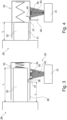
- the Fig. 3 and 4 show a wear detection system 29 with a transponder unit 30 and a transmitting-receiving unit 31 as well as a carbon brush 32.
- the carbon brush 32 is inserted into a holder 33, on the outer surface 34 of which the transponder unit 30 is firmly fixed.
- a shielding device 35 is formed from a cover element 36 made of metal, which is held on a wall 38 of the holder 33 so as to be pivotable about an axis 37.
- the cover element 36 is designed in the manner of a rocker with an outer end 39 for shielding the transponder unit 30 and an inner end 40 for contact with a side surface 41 of the carbon brush 32.
- the inner end 40 of the cover element 36 rests on the side surface 41 of the carbon brush 32 in such a way that the outer end 39 of the cover element 36 shields the transponder unit 30 against electromagnetic radiation or a signal 42 of the transmitting/receiving unit 31.
- the inner end 40 can no longer rest on the side surface 41, so that the cover element 36 is suddenly released due to a force not shown in detail here, for example by a spring or weight, so that it is pivoted about the axis 37 and the outer end 39 no longer shields the transponder unit 30.
- the signal 42 can now be received by the transponder unit 30, whereby the transponder unit 30 sends a signal 43 back to the transmitting/receiving unit 31.
- the transmitting/receiving unit 31 can now register an exceedance of a length l3 of the carbon brush 32 and, if necessary, forward it to a higher-level machine control.
Landscapes
- Engineering & Computer Science (AREA)
- General Engineering & Computer Science (AREA)
- Mechanical Engineering (AREA)
- Power Engineering (AREA)
- Microelectronics & Electronic Packaging (AREA)
- Braking Arrangements (AREA)
- Transplanting Machines (AREA)
- Motor Or Generator Current Collectors (AREA)
Description
Die Erfindung betrifft ein Verschleißerkennungssystem sowie ein Verfahren zur Verschleißerkennung, insbesondere für Reibelemente, wie Bürsten, Reibbelege, Bremsbelege, Schmierstücke oder dergleichen, mit zumindest einem konsumierbaren Reibelement, und einer Transpondereinheit, wobei die Transpondereinheit mit einer Sende-Empfangseinheit drahtlos kommunizieren kann.The invention relates to a wear detection system and a method for wear detection, in particular for friction elements such as brushes, friction linings, brake linings, lubricating pieces or the like, with at least one consumable friction element and a transponder unit, wherein the transponder unit can communicate wirelessly with a transmitting-receiving unit.
Reibelemente, wie beispielsweise Kohlebürsten für Elektromotore, Reibbelege zur Kraftübertragung, Bremsbelege und Festschmierstoffstücke, sind grundsätzlich immer einem Verschleiß durch Abrieb von Material des Reibelements unterworfen. Häufig ist es wünschenswert, das Reibelement bereits vor einem Erreichen einer eine Funktion beeinträchtigten Verschleißgrenze auszutauschen. So werden Verschleißerkennungssysteme regelmäßig dazu eingesetzt, einen Verschleißzustand von Reibelementen zu überwachen. Bekannt sind hier elektrische Kontakte an Reibelementen, oder auch Schalter, die ein Erreichen einer Verschleißgrenze signalisieren können. Derartige Verschleißerkennungssysteme erfordern jedoch eine Verkabelung der Kontakte bzw. Schalter mit einer Steuereinheit. Eine derartige Verkabelung ist nur relativ kostenaufwendig herzustellen, insbesondere wenn eine Vielzahl Reibelemente gleichzeitig überwacht werden sollen. So kann eine Verkabelung, für beispielsweise Bürsten eines Generators, auch zur Reduzierung des Verkabelungsaufwands in Art einer Reihenschaltung ausgebildet sein. Welche Bürste das betreffende Signal ausgelöst hat, ist dann jedoch nicht mehr vom Verschleißerkennungssystem erkennbar.Friction elements, such as carbon brushes for electric motors, friction linings for power transmission, brake linings and solid lubricant pieces, are always subject to wear due to abrasion of the friction element material. It is often desirable to replace the friction element before it reaches a wear limit that impairs its function. Wear detection systems are therefore regularly used to monitor the wear status of friction elements. Electrical contacts on friction elements or switches that can signal when a wear limit is reached are well known here. However, such wear detection systems require wiring of the Contacts or switches with a control unit. Such wiring is relatively expensive to produce, especially if a large number of friction elements are to be monitored simultaneously. For example, wiring for brushes on a generator can be designed in a series circuit to reduce the wiring effort. However, the wear detection system can then no longer identify which brush triggered the signal in question.
Weiter ist es bekannt, Reibelemente mit einer Transpondereinheit zu versehen, die mit einer Sende-Empfangseinheit drahtlos kommunizieren kann, wodurch eine aufwendige Verkabelung der Reibelemente entfällt. Die
Das bekannte Verschleißerkennungssystem weist den Nachteil auf, dass eine Zerstörung der Transpondereinheit bei Erreichen der Verschleißgrenze zwingend erforderlich ist. Die Transpondereinheit muss daher so ausgebildet sein bzw. so an der Kohlebürste befestigt sein, dass sie bei Erreichen der Verschleißgrenze bzw. der Reibfläche sicher zerstört wird. Kostengünstige Transpondereinheiten, wie Sie beispielsweise in Etikettenform erhältlich sind, können daher hier keine Verwendung finden, da sich die Etiketten durch Wärmeeinwirkung in unmittelbarer Nähe der Reibfläche ablösen können oder aufgrund einer mangelhaften Haftung an der Kohlebürste nicht mechanisch zerstört werden können.The known wear detection system has the disadvantage that the transponder unit must be destroyed when the wear limit is reached. The transponder unit must therefore be designed or attached to the carbon brush in such a way that it is reliably destroyed when the wear limit or the friction surface is reached. Inexpensive transponder units, such as those available in label form, cannot therefore be used here, as the labels can come off due to heat in the immediate vicinity of the friction surface or cannot be mechanically destroyed due to poor adhesion to the carbon brush.
Auch können nur weitergehende Informationen über einen Verschleißzustand eines Reibelements vor Erreichen einer Verschleißgrenze ermittelt werden, wenn eine Transpondereinheit ergänzend mit Messwertaufnehmern ausgestattet ist. So kann die Transpondereinheit an einer beliebigen, für eine Montage gut geeignete Position an einem Reibelement befestigt sein, wobei die Transpondereinheit beispielsweise über Kabel mit einem Messwertaufnehmer oder einem einfachen im Bereich einer Verschleißgrenze des Reibelements angebrachten Kontakts verbunden ist. So sind Transpondereinheiten, die einer Zerstörung bedürfen, nur aufwendig zu befestigen, und solche, die mit Messwertaufnehmern und Verbindungskabeln ausgestattet sind vergleichsweise teuer.Further information about the state of wear of a friction element before a wear limit is reached can only be determined if a transponder unit is additionally equipped with measuring sensors. The transponder unit can be attached to a friction element in any position that is suitable for installation, with the transponder unit being connected, for example, via a cable to a measuring sensor or a simple contact attached in the area of a wear limit of the friction element. Transponder units that need to be destroyed are therefore difficult to attach, and those that are equipped with measuring sensors and connecting cables are comparatively expensive.
Andere Verschleißerkennungssysteme sind aus
Der vorliegenden Erfindung liegt daher die Aufgabe zugrunde, ein Verschleißerkennungssystem und ein Verfahren zur Verschleißerkennung vorzuschlagen, welches eine kostengünstige und einfache Verschleißüberwachung von Reibelementen ermöglicht.The present invention is therefore based on the object of proposing a wear detection system and a method for wear detection, which enables cost-effective and simple wear monitoring of friction elements.
Diese Aufgabe wird durch ein Verschleißerkennungssystem mit den Merkmalen des Anspruchs 1 und ein Verfahren zur Verschleißerkennung mit den Merkmalen des Anspruchs 6 gelöst.This object is achieved by a wear detection system having the features of claim 1 and a method for wear detection having the features of claim 6.
Das erfindungsgemäße Verschleißerkennungssystem, insbesondere für Reibelemente, wie Bürsten, Reibbelege, Bremsbelege, Schmierstücke oder dergleichen, umfasst zumindest ein konsumierbares Reibelement und eine Transpondereinheit, wobei die Transpondereinheit mit einer Sende-Empfangseinheit drahtlos kommunizieren kann, wobei das Verschleißerkennungssystem eine Abschirmeinrichtung aufweist, wobei die Abschirmeinrichtung so ausgebildet ist, dass mittels der Abschirmeinrichtung die Transpondereinheit in Abhängigkeit eines Verschleißzustandes des Reibelements zumindest teilweise abschirmbar ist, derart, dass eine Kommunikation zwischen der Transpondereinheit und der Sende-Empfangseinheit beeinflussbar ist, wobei das Verschleißerkennungssystem eine Haltevorrichtung umfasst, die zur bewegbaren Positionierung des Reibelements relativ zu einer Reibfläche dient, wobei die Transpondereinheit ortsfest mit der Haltevorrichtung verbunden ist, wobei die Abschirmeinrichtung als ein an der Haltevorrichtung angeordnetes Abschirmelement ausgebildet ist, welches die Transpondereinheit abschirmend abdecken oder freigeben kann, wenn eine Bewegung des Reibelements relativ zu der Haltevorrichtung erfolgt.The wear detection system according to the invention, in particular for friction elements such as brushes, friction linings, brake linings, lubricating pieces or the like, comprises at least one consumable friction element and a transponder unit, wherein the transponder unit can communicate wirelessly with a transmitting-receiving unit, wherein the wear detection system has a shielding device, wherein the shielding device is designed such that the transponder unit can be at least partially shielded by means of the shielding device depending on a wear state of the friction element, such that communication between the transponder unit and the transmitting-receiving unit can be influenced, wherein the wear detection system comprises a holding device which is used for the movable positioning of the friction element relative to a friction surface serves, wherein the transponder unit is fixedly connected to the holding device, wherein the shielding device is designed as a shielding element arranged on the holding device, which can cover or uncover the transponder unit when a movement of the friction element occurs relative to the holding device.
Durch die Beeinflussung der Transpondereinheit durch eine davon unabhängig ausgebildete Abschirmeinrichtung, ist es möglich, eine Kommunikationsverbindung zwischen der Transpondereinheit und der Sende-Empfangseinheit zu verändern, zu unterbinden oder überhaupt erst zu ermöglichen. Da das von der Sende-Empfangseinheit empfangene Signal der Transpondereinheit im Wesentlichen alleine von der Abschirmeinrichtung beeinflusst wird, kann als eine Transpondereinheit nahezu jede beliebige Transpondereinheit, insbesondere eine kostengünstige Transpondereinheit verwendet werden. Weiter wird eine Kommunikation zwischen der Transpondereinheit und der Sende-Empfangseinheit wesentlich vereinfacht, da der Inhalt der übertragenden Daten grundsätzlich unerheblich ist. Es kommt lediglich darauf an, dass die Transpondereinheit von der Sende-Empfangseinheit überhaupt erfasst bzw. erkannt wird. Auch ist zur Ausbildung der Abschirmeinrichtung nicht zwangsläufig eine Integration eines neuen Bauteils oder einer neuen Baueinheit notwendig. Vielmehr können die im Umgebungsbereich des Reibelements ohnehin vorhandenen Bauteile zur Ausbildung der Abschirmeinrichtung genutzt werden, so dass dafür keine weiteren Kosten entstehen. Auch ist es dann nicht mehr notwendig die Transpondereinheit unmittelbar am Reibelement zu befestigen oder die Transpondereinheit so am Reibelement zu befestigen, dass eine Zerstörung der Transpondereinheit sicher gewährleistet ist. Das Erreichen einer Verschleißgrenze des Reibelements ist von der Sende-Empfangseinheit durch eine Veränderung eines Antwortsignals der Transpondereinheit detektierbar oder alternativ durch ein Ausbleiben des Transpondersignals nach vorherigem Empfang bzw. durch einen Empfang nach einem vorherigem Ausbleiben des Transpondersignals.By influencing the transponder unit with an independently designed shielding device, it is possible to change, prevent or even enable a communication connection between the transponder unit and the transmitting/receiving unit. Since the signal received by the transponder unit from the transmitting/receiving unit is essentially influenced solely by the shielding device, almost any transponder unit, in particular a cost-effective transponder unit, can be used as a transponder unit. Furthermore, communication between the transponder unit and the transmitting/receiving unit is made significantly easier, since the content of the transmitted data is fundamentally irrelevant. It only matters that the transponder unit is detected or recognized by the transmitting/receiving unit. It is also not necessarily necessary to integrate a new component or a new assembly to form the shielding device. Rather, the components that are already present in the area surrounding the friction element can be used to form the shielding device, so that no additional costs are incurred. It is then no longer necessary to attach the transponder unit directly to the friction element or to attach the transponder unit to the friction element in such a way that the transponder unit is guaranteed not to be destroyed. The transmission/reception unit can detect that the friction element has reached its wear limit by changing the response signal from the transponder unit or, alternatively, by the transponder signal not being received after it had previously been received or by a transponder signal not being received after it had previously been received.
Erfindungsgemäß umfasst das Verschleißerkennungssystem eine Haltevorrichtung, die zur bewegbaren Positionierung des Reibelements relativ zu einer Reibfläche und zur Kontaktierung des Reibelements mit der Reibfläche dient. Das Reibelement kann demnach von der Haltevorrichtung gehaltert bzw. aufgenommen sein und beispielsweise mittels einer Federeinrichtung oder eines Aktuators gegen eine Reibfläche mit einer Andruckkraft gedrückt werden. Beispielsweise kann das Reibelement monolithisch mit einer Quaderform oder auch stabförmig ausgebildet sein und so von der Haltevorrichtung aufgenommen sein, dass es im Wesentlichen ortogonal zur Reibfläche in der Haltevorrichtung bewegbar ist. Die infolge von Verschleiß des Reibelements bewirkte Längenminderung und Längsbewegung des Reibelements relativ zur Haltevorrichtung kann dann die Kommunikation zwischen der Transpondereinheit und der Sende-Empfangseinheit mittels der Abschirmeinrichtung beeinflussen.According to the invention, the wear detection system comprises a holding device which serves for the movable positioning of the friction element relative to a friction surface and for contacting the friction element with the friction surface. The friction element can therefore be held or received by the holding device and pressed against a friction surface with a pressing force, for example by means of a spring device or an actuator. For example, the friction element can be monolithic with a cuboid shape or rod-shaped and can be received by the holding device in such a way that it can be moved essentially orthogonally to the friction surface in the holding device. The reduction in length and longitudinal movement of the friction element relative to the holding device caused by wear of the friction element can then influence the communication between the transponder unit and the transceiver unit by means of the shielding device.
Erfindungsgemäß ist die Transpondereinheit ortsfest mit der Haltevorrichtung verbunden, wobei die Abschirmeinrichtung als ein an der Haltevorrichtung angeordnetes Abschirmelement ausgebildet ist, welches die Transpondereinheit abschirmend abdeckt oder freigibt, wenn eine Bewegung des Reibelements relativ zu der Haltevorrichtung erfolgt. Demnach kann die Transpondereinheit beispielsweise unmittelbar auf einer Oberfläche der Haltevorrichtung befestigt sein, ohne dass die Transpondereinheit mit dem Reibelement in Kontakt steht. Die Abschirmeinrichtung ist von einem Abschirmelement ausgebildet, welches in Abhängigkeit einer Längenänderung des Reibelements die Transpondereinheit abschirmend abdeckt oder zur Kommunikation mit der Sende-Empfangseinheit freigibt. Das Abschirmelement kann beispielsweise als ein einfaches Metallblech ausgebildet sein, welches nach einer Passage eines Endes des Reibelements relativ zur Transpondereinheit bewegt wird. Eine derartige Abschirmeinrichtung ist ebenfalls kostengünstig auszubilden und ermöglicht eine besonders sichere Übertragung bzw. Kommunikation zwischen der Transpondereinheit und der Sende-Empfangseinheit, weil die Transpondereinheit durch die Trennung von dem Reibelement keinen hohen Temperaturen oder Vibrationen ausgesetzt ist. Insbesondere wenn die Haltevorrichtung aus einem Kunststoffmaterial ausgebildet ist wird dann auch eine Resonanzfrequenz von beispielsweise einer RFID-Transpondereinheit mit Ausnahme des Abschirmelementes kaum von Umgebungsmaterialien beeinflusst.According to the invention, the transponder unit is connected in a fixed position to the holding device, wherein the shielding device is designed as a shielding element arranged on the holding device, which covers the transponder unit in a shielding manner or releases it when the friction element moves relative to the holding device. Accordingly, the transponder unit can, for example, be attached directly to a surface of the holding device without the transponder unit being in contact with the friction element. The shielding device is designed as a shielding element which, depending on a change in the length of the friction element, covers the transponder unit in a shielding manner or releases it for communication with the transceiver unit. The shielding element can, for example, be designed as a simple metal sheet which is moved relative to the transponder unit after one end of the friction element has passed through. Such a shielding device can also be designed inexpensively and enables particularly secure transmission or communication between the transponder unit and the transmitting/receiving unit, because the transponder unit is not exposed to high temperatures or vibrations due to the separation from the friction element. In particular, if the holding device is made of a plastic material, a resonance frequency of, for example, an RFID transponder unit is then hardly influenced by surrounding materials with the exception of the shielding element.
In einer Ausführungsform kann die Transpondereinheit eine Codierung aufweisen, die von der Sende-Empfangseinheit empfangbar ist. Die Codierung kann als ein Schaltsignal genutzt werden, um zum Beispiel eine Maschine in Betrieb setzen zu können. Wird ein Reibelement in die Maschine eingebaut, das eine vorgegebene Codierung nicht aufweist, kann ein entsprechendes Schaltsignal nicht erzeugt werden, so dass infolge dessen die Maschine nicht in Betrieb genommen werden kann. Somit ist sichergestellt, dass nur für die Maschine zugelassene Reibelemente eingesetzt werden können. Wenn eine Vielzahl von Reibelementen verwendet wird, wird es weiter auch möglich festzustellen, welches der Reibelemente ausgefallenen bzw. verschlissen ist, wenn jedes Reibelement eine individuelle Codierung mittels der Transpondereinheit aufweist. Das Verschleißerkennungssystem kann zu derartigen Steuerzwecken mit einer Steuereinheit bzw. einer Maschinensteuerung verbunden sein.In one embodiment, the transponder unit can have a code that can be received by the transceiver unit. The code can be used as a switching signal, for example to be able to start a machine. If a friction element is installed in the machine that does not have a predetermined code, a corresponding switching signal cannot be generated, so that as a result the machine cannot be started. This ensures that only friction elements approved for the machine can be used. If a large number of friction elements are used, it is also possible to determine which of the friction elements has failed or is worn if each friction element has an individual code using the transponder unit. The wear detection system can be connected to a control unit or a machine control system for such control purposes.
Vorteilhaft kann die Transpondereinheit eine RFID-Transpondereinheit sein. Zwar ist auch ein Einsatz einer Transpondereinheit denkbar, die beispielsweise auf optischer Übertragungstechnik basiert, jedoch sind RFID-Transpondereinheiten vergleichsweise kostengünstig, und auch in Form eines Klebeetiketts, verfügbar. Vorzugsweise können passive RFID-Traspondereinheiten Verwendung finden, da diese keine externe Stromversorgung benötigen. Weiter ist ein Funksignal zwischen der RFID-Transpondereinheit und der Sende-Empfangseinheit mittels der Abschirmeinrichtung unaufwendig beeinflussbar. So kann eine Resonanzfrequenz einer Antenne der RFID-Transpondereinheit leicht durch ein Abdecken der Antenne oder durch einen elektrischen Leiter in der Nähe der Antenne so beeinflusst werden, dass das Funksignal stark gedämpft oder vollständig abgeschirmt wird.The transponder unit can advantageously be an RFID transponder unit. It is also conceivable to use a transponder unit based on optical transmission technology, for example, but RFID transponder units are comparatively inexpensive and are also available in the form of an adhesive label. Passive RFID transponder units can preferably be used, as they do not require an external power supply. Furthermore, a radio signal between the RFID transponder unit and the transmitter-receiver unit can be easily influenced using the shielding device. In this way, a resonance frequency an antenna of the RFID transponder unit can easily be influenced by covering the antenna or by an electrical conductor near the antenna so that the radio signal is strongly attenuated or completely shielded.
Das Reibelement kann beispielsweise ein Kontaktstück zur Übertragung elektrischer Energie, wie eine Kohlebürste für einen Elektromotor oder Generator, sein. Das Verschleißerkennungssystem kann insbesondere dann effektiv eingesetzt werden, wenn ein Elektromotor über eine Vielzahl von Kohlebürsten verfügt, die regelmäßig aufgrund von Verschleiß oder Beschädigung ausgewechselt werden müssen. Ein derartiges Verschleißerkennungssystem ist insbesondere dann vorteilhaft einsetzbar, wenn die Kohlebürsten nicht ohne Weiteres gewartet werden können, wie zum Beispiel in einer Windkraftanlage. Rein grundsätzlich kann das Verschleißerkennungssystem jedoch auch für andere Typen von Reibelementen eingesetzt werden, wie beispielsweise alle Arten von Reibbelegen, Bremsbelegen oder für Trockenschmierkörper.The friction element can be, for example, a contact piece for transmitting electrical energy, such as a carbon brush for an electric motor or generator. The wear detection system can be used effectively in particular when an electric motor has a large number of carbon brushes that have to be replaced regularly due to wear or damage. Such a wear detection system can be used particularly advantageously when the carbon brushes cannot be easily maintained, such as in a wind turbine. In principle, however, the wear detection system can also be used for other types of friction elements, such as all types of friction linings, brake linings or dry lubricants.
Eine kontrollierte Abschirmung der Transpondereinheit kann dadurch ermöglicht werden, dass die Abschirmeinrichtung der Transpondereinheit unmittelbar benachbart angeordnet ist. Sofern die Transpondereinheit eine Antenne aufweist, kann diese so durch ein mit elektromagnetischer Strahlung wechselwirkendes Material, wie beispielsweise ein Metallwerkstoff, direkt abgeschirmt werden. Das Material oder auch die daraus ausgebildete Abschirmeinrichtung deckt die Transpondereinheit immer vollständig ab, wobei dann eine Permittivität der Abschirmeinrichtung ungleichmäßig relativ zur Transpondereinheit ausgebildet ist, so dass zumindest in einer Position der Transpondereinheit relativ zur Abschirmeinrichtung, oder bei einem vollständigen oder teilweisen Entfernen der Abschirmeinrichtung, eine Kommunikation mit der Sende-Empfangseinheit möglich ist. Insgesamt kann durch die unmittelbare Anordnung der Abschirmeinrichtung in Nähe der Transpondereinheit eine Lageänderung des Reibelements relativ zur Abschirmeinrichtung und/oder zur Transpondereinheit durch eine Kommunikation der Transpondereinheit mit der Sende-Empfangseinheit detektiert werden.Controlled shielding of the transponder unit can be made possible by arranging the shielding device directly adjacent to the transponder unit. If the transponder unit has an antenna, this can be directly shielded by a material that interacts with electromagnetic radiation, such as a metal material. The material or the shielding device formed from it always completely covers the transponder unit, whereby a permittivity of the shielding device is then formed unevenly relative to the transponder unit, so that communication with the transmitting-receiving unit is possible at least in one position of the transponder unit relative to the shielding device, or when the shielding device is completely or partially removed. Overall, the direct arrangement of the shielding device near the transponder unit allows a change in the position of the friction element relative to the shielding device. and/or to the transponder unit through communication between the transponder unit and the transmitting-receiving unit.
Bei dem erfindungsgemäßen Verfahren zur Verschleißerkennung, insbesondere für Reibelemente wie Bürsten, Reibbelege, Bremsbelege, Schmierstücke oder dergleichen, mit zumindest einem konsumierbaren Reibelement und einer Transpondereinheit, kann die Transpondereinheit mit einer Sende-Empfangseinheit drahtlos kommunizieren, wobei mittels einer Abschirmeinrichtung die Transpondereinheit in Abhängigkeit eines Verschleißzustandes des Reibelements zumindest teilweise abgeschirmt wird, derart, dass eine Kommunikation zwischen der Transpondereinheit und der Sende-Empfangseinheit beeinflusst wird, wobei das Verschleißerkennungssystem eine Haltevorrichtung umfasst, mittels der eine bewegbare Positionierung des Reibelements relativ zu einer Reibfläche erfolgt, wobei die Transpondereinheit ortsfest mit der Haltevorrichtung verbunden ist, wobei die Abschirmeinrichtung als ein an der Haltevorrichtung angeordnetes Abschirmelement ausgebildet ist, mittels dem die Transpondereinheit abschirmend abdeckt oder freigeben wird, wenn eine Bewegung des Reibelements relativ zu der Haltevorrichtung erfolgt. Eine durch Verschleiß bedingte Längenänderung des Reibelements kann so eine Positionsänderung der Transpondereinheit relativ zu der Abschirmeinrichtung bewirken. Die Vorteile des Verfahrens zur Verschleißerkennung betreffend wird auf die nähere Beschreibung des erfindungsgemäßen Verschleißerkennungssystems verwiesen.In the method according to the invention for detecting wear, in particular for friction elements such as brushes, friction linings, brake linings, lubricating pieces or the like, with at least one consumable friction element and a transponder unit, the transponder unit can communicate wirelessly with a transmitting/receiving unit, wherein the transponder unit is at least partially shielded by means of a shielding device depending on a state of wear of the friction element, such that communication between the transponder unit and the transmitting/receiving unit is influenced, wherein the wear detection system comprises a holding device by means of which a movable positioning of the friction element takes place relative to a friction surface, wherein the transponder unit is connected in a fixed position to the holding device, wherein the shielding device is designed as a shielding element arranged on the holding device, by means of which the transponder unit is shielded or released when a movement of the friction element takes place relative to the holding device. A change in the length of the friction element caused by wear can thus cause a change in the position of the transponder unit relative to the shielding device. Regarding the advantages of the method for detecting wear, reference is made to the more detailed description of the wear detection system according to the invention.
Das Verfahren kann besonders einfach ausgeführt werden, wenn die Abschirmeinrichtung eine Permittivität eines räumlichen Übertragungsbereiches der Transpondereinheit verändert. So kann die Abschirmeinrichtung in dem Raum zwischenliegend der Transpondereinheit und der Sende-Empfangseinheit, der zur Übertragung von Sende- oder Empfangssignalen genutzt wird, angeordnet sein und die Sende- bzw. Empfangssignale durch eine Änderung der Permittivität des betreffenden Raumes beeinflussen. Bei elektromagnetischen Übertragungsverfahren kann dies beispielsweise durch Einbringen von elektrisch leitfähigen Materialien in den Raum oder ein entsprechendes Entfernen erfolgen. Wenn dies in Abhängigkeit eines Verschleißzustandes des Reibelements geschieht, kann aus einer Änderung der Permittivität auf einen Verschleißzustand rückgeschlossen werden.The method can be carried out particularly simply if the shielding device changes a permittivity of a spatial transmission area of the transponder unit. The shielding device can be arranged in the space between the transponder unit and the transmitting-receiving unit, which is used to transmit transmit or receive signals, and the transmit or receive signals can be changed by changing the permittivity of the relevant space. In electromagnetic transmission processes, this can be done, for example, by introducing electrically conductive materials into the space or removing them accordingly. If this happens depending on the wear condition of the friction element, a change in the permittivity can be used to infer a wear condition.
Dies kann auch durch eine verschleißbedingte Maßänderung des Reibelements bewirkt werden, durch die eine Abschirmung oder eine Beseitigung einer Abschirmung der Transpondereinheit erfolgen kann. Ein durch Abrasion bedingter Verschleiß des Reibelements geht mit einer Maßänderung desselben einher, wobei die Maßänderung, wie beispielsweise eine Längenänderung oder ein Abrieb einer Oberfläche, zur Folge haben kann, dass die Transpondereinheit abgeschirmt wird, oder wahlweise eine Abschirmung der Transpondereinheit beseitigt wird. Somit geht ein Verschleiß des Reibelements mit einer Änderung eines Empfangssignals der Transpondereinheit einher, welche von der Sende-Empfangseinheit detektiert werden kann, und aus der Rückschlüsse auf einem Verschleißzustand des Reibelements gezogen werden können.This can also be caused by a wear-related dimensional change of the friction element, which can result in shielding or removal of shielding of the transponder unit. Wear of the friction element caused by abrasion is accompanied by a dimensional change of the same, whereby the dimensional change, such as a change in length or abrasion of a surface, can result in the transponder unit being shielded or, alternatively, the shielding of the transponder unit being removed. Wear of the friction element is thus accompanied by a change in a received signal of the transponder unit, which can be detected by the transmitting/receiving unit and from which conclusions can be drawn about the state of wear of the friction element.
Somit kann in Abhängigkeit einer Position der Transpondereinheit relativ zu einer von dem Reibelement kontaktierten Reibfläche eine Abschirmung oder eine Beseitigung einer Abschirmung der Transpondereinheit erfolgen.Thus, depending on a position of the transponder unit relative to a friction surface contacted by the friction element, shielding of the transponder unit or removal of shielding can take place.
Weitere vorteilhafte Ausführungsformen des Verfahrens ergeben sich aus den Merkmalsbeschreibungen der auf den Vorrichtungsanspruch 1 rückbezogenen Unteransprüche.Further advantageous embodiments of the method emerge from the feature descriptions of the subclaims referring back to device claim 1.
Nachfolgend wird eine bevorzugte Ausführungsform der Erfindung unter Bezugnahme auf die beigefügten Zeichnungen näher erläutert.A preferred embodiment of the invention is explained in more detail below with reference to the accompanying drawings.
Es zeigen:
- Fig. 1
- eine erste, nicht mit der Erfindung übereinstimmende Ausführungsform eines Verschleißerkennungssystems in einer schematischen Darstellung;
- Fig. 2
- das Verschleißerkennungssystem nach der ersten Ausführungsform mit einem gegenüber der
Fig. 1 veränderten Verschleißzustand; - Fig. 3
- eine zweite Ausführungsform eines Verschleißerkennungssystems in einer schematischen Darstellung;
- Fig. 4
- das Verschleißerkennungssystem nach der zweiten Ausführungsform mit einem gegenüber der
Fig. 3 veränderten Verschleißzustand.
- Fig. 1
- a first embodiment of a wear detection system not in accordance with the invention in a schematic representation;
- Fig. 2
- the wear detection system according to the first embodiment with a
Fig. 1 changed state of wear; - Fig. 3
- a second embodiment of a wear detection system in a schematic representation;
- Fig. 4
- the wear detection system according to the second embodiment with a
Fig. 3 changed state of wear.
Wie aus
Bei einem Verschleiß eines vorderen Endes 25 der Kohlebürste 13 vermindert sich die Länge L1 auf die hier in
Die
Wie aus
Claims (9)
- A wear detection system (29), in particular for friction elements, such as brushes, friction linings, brake linings, lubrication pieces or the like, comprising at least one consumable friction element and a transponder unit (30), wherein the transponder unit can communicate wirelessly with a transmitter-receiver unit (31), wherein the wear detection system comprises a shielding device (35), said shielding device being configured in such a manner that by means of the shielding device, the transponder unit can be at least partially shielded as a function of a wear condition of the friction element, such that communication between the transponder unit and the transmitter-receiver unit can be influenced, characterized in that
the wear detection system comprises a support structure (33) which serves to movably position the friction element relative to a friction surface, the transponder unit being immovably connected to the support structure, the shielding device being formed as a shielding element (36), which is arranged at the support structure and which can cover the transponder unit in a shielding manner or uncover it when a motion of the friction element relative to the support structure occurs. - The wear detection system according to claim 1,
characterized in that
the transponder unit (30) has a coding that can be received by the transmitter-receiver unit (31). - The wear detection system according to claim 1 or 2, characterized in that
the transponder unit (30) is an RFID transponder unit. - The wear detection system according to any of the preceding claims,
characterized in that
the friction element is a contact piece (32) for transmitting electric energy. - The wear detection system according to any of the preceding claims,
characterized in that
the shielding device (35) is arranged directly adjacent to the transponder unit (30). - A method for detecting wear, in particular for friction elements, such as brushes, friction linings, brake linings, lubrication pieces or the like, comprising at least one consumable friction element, and comprising a transponder unit (30), wherein the transponder unit can communicate wirelessly with a transmitter-receiver unit (31),
characterized in that
by means of a shielding device (35), the transponder unit is at least partially shielded as a function of a wear condition of the friction element, such that communication between the transponder unit and the transmitter-receiver unit is influenced, the wear detection system comprising a support structure (33) which serves to movably position the friction element relative to a friction surface (16), the transponder unit being immovably connected to the support structure, the shielding device being formed as a shielding element (36), which is arranged at the support structure and by means of which the transponder unit is covered in a shielding manner or uncovered when a motion of the friction element relative to the support structure occurs. - The method according to claim 6,
characterized in that
the shielding device (35) changes a permittivity of a spatial transmission range of the transponder unit (30). - The method according to claim 6 or 7,
characterized in that
by means of a wear-related dimensional change of the friction element, a shielding or an elimination of a shielding of the transponder unit (30) takes place. - The method according to any of the claims 6 to 8, characterized in that
as a function of a position of the transponder unit (30) relative to a friction surface contacted by the friction element, a shielding or an elimination of a shielding of the transponder unit takes place.
Applications Claiming Priority (3)
| Application Number | Priority Date | Filing Date | Title |
|---|---|---|---|
| DE102011005302A DE102011005302B4 (en) | 2011-03-09 | 2011-03-09 | Wear detection system and method |
| PCT/EP2012/052291 WO2012119832A1 (en) | 2011-03-09 | 2012-02-10 | Wear detection system and method |
| EP12709810.1A EP2683561B1 (en) | 2011-03-09 | 2012-02-10 | Wear detection system and method |
Related Parent Applications (1)
| Application Number | Title | Priority Date | Filing Date |
|---|---|---|---|
| EP12709810.1A Division EP2683561B1 (en) | 2011-03-09 | 2012-02-10 | Wear detection system and method |
Publications (2)
| Publication Number | Publication Date |
|---|---|
| EP4046828A1 EP4046828A1 (en) | 2022-08-24 |
| EP4046828B1 true EP4046828B1 (en) | 2024-12-18 |
Family
ID=45872908
Family Applications (2)
| Application Number | Title | Priority Date | Filing Date |
|---|---|---|---|
| EP22162605.4A Active EP4046828B1 (en) | 2011-03-09 | 2012-02-10 | Wear detection system and method |
| EP12709810.1A Active EP2683561B1 (en) | 2011-03-09 | 2012-02-10 | Wear detection system and method |
Family Applications After (1)
| Application Number | Title | Priority Date | Filing Date |
|---|---|---|---|
| EP12709810.1A Active EP2683561B1 (en) | 2011-03-09 | 2012-02-10 | Wear detection system and method |
Country Status (8)
| Country | Link |
|---|---|
| US (1) | US20140091918A1 (en) |
| EP (2) | EP4046828B1 (en) |
| JP (1) | JP2014509823A (en) |
| KR (1) | KR101536499B1 (en) |
| CN (1) | CN103561972A (en) |
| DE (1) | DE102011005302B4 (en) |
| ES (1) | ES2917878T3 (en) |
| WO (1) | WO2012119832A1 (en) |
Families Citing this family (23)
| Publication number | Priority date | Publication date | Assignee | Title |
|---|---|---|---|---|
| JP6059931B2 (en) * | 2012-09-24 | 2017-01-11 | 株式会社ディスコ | Cutting equipment |
| US9252643B2 (en) | 2013-03-14 | 2016-02-02 | Cutsforth, Inc. | System and method for monitoring the status of one or more components of an electrical machine |
| DE102013014534B3 (en) * | 2013-09-03 | 2014-05-22 | Sew-Eurodrive Gmbh & Co Kg | Arrangement for detecting wear of motor i.e. electromotor, has transmitter supplying electrical power from transformation unit to arrangement, where unit comprises piezoelectric element, which carries out rotation and vibration of motor |
| WO2015160656A1 (en) * | 2014-04-16 | 2015-10-22 | Flsmidth A/S | Methods and apparatus for the continuous monitoring of wear in flotation circuits |
| US9762015B2 (en) * | 2014-06-10 | 2017-09-12 | General Electric Company | Brush holder apparatus and system |
| DE102014017895A1 (en) * | 2014-12-03 | 2016-06-09 | Dürr Systems GmbH | Application system component with transponder and / or wear detection device |
| US10189098B2 (en) * | 2015-03-12 | 2019-01-29 | Robert Bosch Tool Corporation | Diagnostic and maintenance operation for a saw |
| WO2016196484A1 (en) | 2015-06-01 | 2016-12-08 | Cutsforth, Inc. | Brush wear and vibration monitoring |
| CN105337134B (en) * | 2015-12-01 | 2017-12-01 | 南京钢铁股份有限公司 | A kind of carbon brush of direct current motor for checking the life-span |
| CN105403417B (en) * | 2015-12-15 | 2017-09-29 | 长春轨道客车股份有限公司 | Rail vehicle axle head grounding device wear test platform |
| AU2017206696A1 (en) | 2016-01-11 | 2018-07-05 | Cutsforth, Inc. | Monitoring system for grounding apparatus |
| US20170307036A1 (en) * | 2016-04-20 | 2017-10-26 | GM Global Technology Operations LLC | Brake telemetry systems and methods |
| DE102016116998B8 (en) * | 2016-09-09 | 2018-05-17 | Saf-Holland Gmbh | Wear sensing |
| WO2018071569A1 (en) * | 2016-10-12 | 2018-04-19 | Rei, Inc. | Method and system for wear monitoring using rf reflections |
| DE102017115744A1 (en) * | 2017-07-13 | 2019-01-17 | Conductix-Wampfler Gmbh | Device and method for detecting the wear of a sliding contact and conductor rail system |
| JP6886369B2 (en) * | 2017-08-29 | 2021-06-16 | 川崎重工業株式会社 | Railroad vehicle brake shoe wear detection unit and its set |
| GB2567888B (en) * | 2017-10-31 | 2020-09-30 | Schrader Electronics Ltd | Tire sensor location method and apparatus |
| CA3114764A1 (en) | 2018-10-04 | 2020-04-09 | Cutsforth, Inc. | System and method for monitoring the status of one or more components of an electrical machine |
| EP3861605A1 (en) | 2018-10-04 | 2021-08-11 | Cutsforth, Inc. | System and method for monitoring the status of one or more components of an electrical machine |
| EP3734776A1 (en) | 2019-05-02 | 2020-11-04 | Siemens Gamesa Renewable Energy A/S | Brush wear monitoring arrangement and method thereof |
| CN111307202A (en) * | 2019-11-19 | 2020-06-19 | 辽宁红德电碳制品有限公司 | Brush material performance detection device |
| FR3103597B1 (en) * | 2019-11-21 | 2023-10-13 | St Microelectronics Rousset | Method for controlling the relative positioning of two objects and corresponding system |
| KR102755421B1 (en) | 2022-01-04 | 2025-01-14 | 한전케이피에스 주식회사 | Measuring device for checking brush |
Family Cites Families (20)
| Publication number | Priority date | Publication date | Assignee | Title |
|---|---|---|---|---|
| JPS5747871U (en) * | 1980-09-03 | 1982-03-17 | ||
| GB2092390A (en) * | 1981-01-30 | 1982-08-11 | Sbw Engineers Ltd | Detecting component wear |
| JPS59106857A (en) * | 1982-12-07 | 1984-06-20 | Mitsubishi Electric Corp | Brush wear detector |
| JPS59106856A (en) * | 1982-12-07 | 1984-06-20 | Mitsubishi Electric Corp | Brush wear detection device |
| DE3247330A1 (en) * | 1982-12-21 | 1984-06-28 | Brown, Boveri & Cie Ag, 6800 Mannheim | DEVICE FOR MONITORING BRUSH WEAR |
| DE4242861A1 (en) * | 1992-12-18 | 1994-06-23 | Diehl Gmbh & Co | Tyre pressure detecting appts. for vehicle wheel |
| US5525796A (en) * | 1994-06-22 | 1996-06-11 | Mcdonnell Douglas Corporation | Fiber optic sensing apparatus for detecting a fracture in a metallic workpiece and an associated method of attaching a fiber optic sensing element to the metallic workpiece |
| DE19840081B4 (en) * | 1998-09-03 | 2004-08-05 | Contitech Transportbandsysteme Gmbh | System and method for monitoring a layer of an object subject to wear, in particular the top layer of a conveyor belt |
| CN2566050Y (en) * | 2002-08-01 | 2003-08-13 | 司国庆 | Brake wear alarm device for car |
| DE10348884A1 (en) * | 2003-10-14 | 2005-05-25 | Pilz Gmbh & Co. Kg | Safety switch, especially emergency shut-off switch, for safe shut-off of hazardous device has transponder, reader unit arranged so reader unit can read transponder in first position of control element but not in second |
| DE102004001799B4 (en) * | 2004-01-05 | 2008-12-11 | Pantrac Gmbh | Sensor device for signaling wear conditions on grinding wheels |
| DE102004049024B3 (en) * | 2004-09-20 | 2006-04-13 | K.A. Schmersal Holding Kg | Position monitoring device |
| NO20051398D0 (en) * | 2005-03-14 | 2005-03-14 | Terje Donvold | System for control, painting and remote monitoring of solid, liquid or gas substances in a stationary or moving state |
| JP4932222B2 (en) * | 2005-04-13 | 2012-05-16 | 株式会社ブリヂストン | Conveyor belt wear detection device |
| JP2007300745A (en) * | 2006-05-01 | 2007-11-15 | Meidensha Corp | Device for detecting wear of pantograph slider |
| DE102007009423B4 (en) | 2007-02-23 | 2012-03-22 | Schunk Kohlenstofftechnik Gmbh | Device with an electrical contact element and such |
| DE102008032818A1 (en) * | 2007-10-10 | 2009-04-16 | Continental Teves Ag & Co. Ohg | brake shoe |
| DE202008002298U1 (en) * | 2008-02-19 | 2008-04-10 | Data-Complex Gmbh | Devices and system for activating and deactivating at least one transponder |
| EP2112518A1 (en) * | 2008-04-25 | 2009-10-28 | ALSTOM Technology Ltd | Brush wear monitor |
| US8384266B2 (en) * | 2011-03-29 | 2013-02-26 | General Electric Company | Brush wear detector system with wireless sensor |
-
2011
- 2011-03-09 DE DE102011005302A patent/DE102011005302B4/en active Active
-
2012
- 2012-02-10 US US14/003,580 patent/US20140091918A1/en not_active Abandoned
- 2012-02-10 JP JP2013557025A patent/JP2014509823A/en active Pending
- 2012-02-10 EP EP22162605.4A patent/EP4046828B1/en active Active
- 2012-02-10 EP EP12709810.1A patent/EP2683561B1/en active Active
- 2012-02-10 CN CN201280012464.3A patent/CN103561972A/en active Pending
- 2012-02-10 WO PCT/EP2012/052291 patent/WO2012119832A1/en not_active Ceased
- 2012-02-10 ES ES12709810T patent/ES2917878T3/en active Active
- 2012-02-10 KR KR1020137026110A patent/KR101536499B1/en not_active Expired - Fee Related
Also Published As
| Publication number | Publication date |
|---|---|
| CN103561972A (en) | 2014-02-05 |
| US20140091918A1 (en) | 2014-04-03 |
| KR20140013018A (en) | 2014-02-04 |
| WO2012119832A1 (en) | 2012-09-13 |
| JP2014509823A (en) | 2014-04-21 |
| EP4046828A1 (en) | 2022-08-24 |
| ES2917878T3 (en) | 2022-07-12 |
| DE102011005302A1 (en) | 2012-09-13 |
| KR101536499B1 (en) | 2015-07-13 |
| EP2683561A1 (en) | 2014-01-15 |
| DE102011005302B4 (en) | 2012-10-31 |
| EP2683561B1 (en) | 2022-04-06 |
Similar Documents
| Publication | Publication Date | Title |
|---|---|---|
| EP4046828B1 (en) | Wear detection system and method | |
| EP3191733B1 (en) | Brake shoe having a wear indicator | |
| DE102011084229A1 (en) | Temperature sensor of electrical machine e.g. electric motor, has connecting device designed to be resilient so that sensor element is pushed to heat source, and sensor element is fixed relative to heat source | |
| EP2630386B2 (en) | Brake lining wear indicator, disc brake having such an indicator and brake shoes for such a disc brake | |
| EP3064694B1 (en) | Power supply for a wing of a door or a window | |
| EP2423068A1 (en) | Earthing contact | |
| DE102015006345A1 (en) | Electric machine with temperature sensor | |
| EP3309967B1 (en) | Capacitive switching device | |
| EP3264426B1 (en) | Shielded electrical cable and method for producing it | |
| DE102018128178A1 (en) | Electrical machine with integrated temperature sensor and rotor condition detection sensor | |
| DE102012012474A1 (en) | Disc brake assembly with electric pad wear adjuster and speed sensor | |
| DE102014211427A1 (en) | Sensor holder for a hydraulic cylinder and method for fixing a sensor | |
| DE102015206800A1 (en) | Electric central release with bracket-mounted plug and hybrid module with such actuator | |
| DE102014216207B4 (en) | braking device | |
| DE102008062779A1 (en) | Detection device i.e. radiation collector, for contact-less generation of temperature data at motor winding of electrical machine, has surface formed such that multiplexing and aligning of heat radiation takes place in output pins | |
| EP2458693B1 (en) | Slip ring unit | |
| EP4204699B1 (en) | Bearing element with a sensor and a telemetric device | |
| DE102018128176A1 (en) | Electrical machine with an inherent rotor position sensor with an integrated temperature sensor | |
| DE10260070B4 (en) | System with an electric cable | |
| DE102020110311A1 (en) | Device for monitoring a component | |
| WO2008034890A2 (en) | Device for detecting a force and/or a torque | |
| DE102015206096A1 (en) | Shielded cable with clipping conductor | |
| DE102017216924A1 (en) | Actuator, transmission and motor vehicle | |
| DE102010045468A1 (en) | Arrangement for determining twisting of elongate bodies |
Legal Events
| Date | Code | Title | Description |
|---|---|---|---|
| PUAI | Public reference made under article 153(3) epc to a published international application that has entered the european phase |
Free format text: ORIGINAL CODE: 0009012 |
|
| STAA | Information on the status of an ep patent application or granted ep patent |
Free format text: STATUS: THE APPLICATION HAS BEEN PUBLISHED |
|
| AC | Divisional application: reference to earlier application |
Ref document number: 2683561 Country of ref document: EP Kind code of ref document: P |
|
| AK | Designated contracting states |
Kind code of ref document: A1 Designated state(s): AL AT BE BG CH CY CZ DE DK EE ES FI FR GB GR HR HU IE IS IT LI LT LU LV MC MK MT NL NO PL PT RO RS SE SI SK SM TR |
|
| STAA | Information on the status of an ep patent application or granted ep patent |
Free format text: STATUS: REQUEST FOR EXAMINATION WAS MADE |
|
| 17P | Request for examination filed |
Effective date: 20230112 |
|
| RBV | Designated contracting states (corrected) |
Designated state(s): AL AT BE BG CH CY CZ DE DK EE ES FI FR GB GR HR HU IE IS IT LI LT LU LV MC MK MT NL NO PL PT RO RS SE SI SK SM TR |
|
| GRAP | Despatch of communication of intention to grant a patent |
Free format text: ORIGINAL CODE: EPIDOSNIGR1 |
|
| STAA | Information on the status of an ep patent application or granted ep patent |
Free format text: STATUS: GRANT OF PATENT IS INTENDED |
|
| RIC1 | Information provided on ipc code assigned before grant |
Ipc: H01R 39/58 20060101ALI20240612BHEP Ipc: F16D 66/02 20060101ALI20240612BHEP Ipc: B60C 11/24 20060101AFI20240612BHEP |
|
| INTG | Intention to grant announced |
Effective date: 20240710 |
|
| GRAS | Grant fee paid |
Free format text: ORIGINAL CODE: EPIDOSNIGR3 |
|
| GRAA | (expected) grant |
Free format text: ORIGINAL CODE: 0009210 |
|
| STAA | Information on the status of an ep patent application or granted ep patent |
Free format text: STATUS: THE PATENT HAS BEEN GRANTED |
|
| AC | Divisional application: reference to earlier application |
Ref document number: 2683561 Country of ref document: EP Kind code of ref document: P |
|
| AK | Designated contracting states |
Kind code of ref document: B1 Designated state(s): AL AT BE BG CH CY CZ DE DK EE ES FI FR GB GR HR HU IE IS IT LI LT LU LV MC MK MT NL NO PL PT RO RS SE SI SK SM TR |
|
| REG | Reference to a national code |
Ref country code: CH Ref legal event code: EP |
|
| REG | Reference to a national code |
Ref country code: DE Ref legal event code: R096 Ref document number: 502012017288 Country of ref document: DE |
|
| REG | Reference to a national code |
Ref country code: IE Ref legal event code: FG4D Free format text: LANGUAGE OF EP DOCUMENT: GERMAN |
|
| REG | Reference to a national code |
Ref country code: LT Ref legal event code: MG9D |
|
| PG25 | Lapsed in a contracting state [announced via postgrant information from national office to epo] |
Ref country code: HR Free format text: LAPSE BECAUSE OF FAILURE TO SUBMIT A TRANSLATION OF THE DESCRIPTION OR TO PAY THE FEE WITHIN THE PRESCRIBED TIME-LIMIT Effective date: 20241218 |
|
| PG25 | Lapsed in a contracting state [announced via postgrant information from national office to epo] |
Ref country code: FI Free format text: LAPSE BECAUSE OF FAILURE TO SUBMIT A TRANSLATION OF THE DESCRIPTION OR TO PAY THE FEE WITHIN THE PRESCRIBED TIME-LIMIT Effective date: 20241218 |
|
| PG25 | Lapsed in a contracting state [announced via postgrant information from national office to epo] |
Ref country code: BG Free format text: LAPSE BECAUSE OF FAILURE TO SUBMIT A TRANSLATION OF THE DESCRIPTION OR TO PAY THE FEE WITHIN THE PRESCRIBED TIME-LIMIT Effective date: 20241218 |
|
| PG25 | Lapsed in a contracting state [announced via postgrant information from national office to epo] |
Ref country code: NO Free format text: LAPSE BECAUSE OF FAILURE TO SUBMIT A TRANSLATION OF THE DESCRIPTION OR TO PAY THE FEE WITHIN THE PRESCRIBED TIME-LIMIT Effective date: 20250318 |
|
| REG | Reference to a national code |
Ref country code: NL Ref legal event code: MP Effective date: 20241218 |
|
| PG25 | Lapsed in a contracting state [announced via postgrant information from national office to epo] |
Ref country code: LV Free format text: LAPSE BECAUSE OF FAILURE TO SUBMIT A TRANSLATION OF THE DESCRIPTION OR TO PAY THE FEE WITHIN THE PRESCRIBED TIME-LIMIT Effective date: 20241218 Ref country code: GR Free format text: LAPSE BECAUSE OF FAILURE TO SUBMIT A TRANSLATION OF THE DESCRIPTION OR TO PAY THE FEE WITHIN THE PRESCRIBED TIME-LIMIT Effective date: 20250319 |
|
| PG25 | Lapsed in a contracting state [announced via postgrant information from national office to epo] |
Ref country code: RS Free format text: LAPSE BECAUSE OF FAILURE TO SUBMIT A TRANSLATION OF THE DESCRIPTION OR TO PAY THE FEE WITHIN THE PRESCRIBED TIME-LIMIT Effective date: 20250318 |
|
| PG25 | Lapsed in a contracting state [announced via postgrant information from national office to epo] |
Ref country code: NL Free format text: LAPSE BECAUSE OF FAILURE TO SUBMIT A TRANSLATION OF THE DESCRIPTION OR TO PAY THE FEE WITHIN THE PRESCRIBED TIME-LIMIT Effective date: 20241218 |
|
| PG25 | Lapsed in a contracting state [announced via postgrant information from national office to epo] |
Ref country code: SM Free format text: LAPSE BECAUSE OF FAILURE TO SUBMIT A TRANSLATION OF THE DESCRIPTION OR TO PAY THE FEE WITHIN THE PRESCRIBED TIME-LIMIT Effective date: 20241218 |
|
| PG25 | Lapsed in a contracting state [announced via postgrant information from national office to epo] |
Ref country code: PL Free format text: LAPSE BECAUSE OF FAILURE TO SUBMIT A TRANSLATION OF THE DESCRIPTION OR TO PAY THE FEE WITHIN THE PRESCRIBED TIME-LIMIT Effective date: 20241218 |
|
| PG25 | Lapsed in a contracting state [announced via postgrant information from national office to epo] |
Ref country code: ES Free format text: LAPSE BECAUSE OF FAILURE TO SUBMIT A TRANSLATION OF THE DESCRIPTION OR TO PAY THE FEE WITHIN THE PRESCRIBED TIME-LIMIT Effective date: 20241218 |
|
| PG25 | Lapsed in a contracting state [announced via postgrant information from national office to epo] |
Ref country code: IS Free format text: LAPSE BECAUSE OF FAILURE TO SUBMIT A TRANSLATION OF THE DESCRIPTION OR TO PAY THE FEE WITHIN THE PRESCRIBED TIME-LIMIT Effective date: 20250418 |
|
| PG25 | Lapsed in a contracting state [announced via postgrant information from national office to epo] |
Ref country code: PT Free format text: LAPSE BECAUSE OF FAILURE TO SUBMIT A TRANSLATION OF THE DESCRIPTION OR TO PAY THE FEE WITHIN THE PRESCRIBED TIME-LIMIT Effective date: 20250421 |
|
| PG25 | Lapsed in a contracting state [announced via postgrant information from national office to epo] |
Ref country code: EE Free format text: LAPSE BECAUSE OF FAILURE TO SUBMIT A TRANSLATION OF THE DESCRIPTION OR TO PAY THE FEE WITHIN THE PRESCRIBED TIME-LIMIT Effective date: 20241218 |
|
| PG25 | Lapsed in a contracting state [announced via postgrant information from national office to epo] |
Ref country code: RO Free format text: LAPSE BECAUSE OF FAILURE TO SUBMIT A TRANSLATION OF THE DESCRIPTION OR TO PAY THE FEE WITHIN THE PRESCRIBED TIME-LIMIT Effective date: 20241218 |
|
| PG25 | Lapsed in a contracting state [announced via postgrant information from national office to epo] |
Ref country code: SK Free format text: LAPSE BECAUSE OF FAILURE TO SUBMIT A TRANSLATION OF THE DESCRIPTION OR TO PAY THE FEE WITHIN THE PRESCRIBED TIME-LIMIT Effective date: 20241218 |
|
| PG25 | Lapsed in a contracting state [announced via postgrant information from national office to epo] |
Ref country code: CZ Free format text: LAPSE BECAUSE OF FAILURE TO SUBMIT A TRANSLATION OF THE DESCRIPTION OR TO PAY THE FEE WITHIN THE PRESCRIBED TIME-LIMIT Effective date: 20241218 |
|
| PG25 | Lapsed in a contracting state [announced via postgrant information from national office to epo] |
Ref country code: IT Free format text: LAPSE BECAUSE OF FAILURE TO SUBMIT A TRANSLATION OF THE DESCRIPTION OR TO PAY THE FEE WITHIN THE PRESCRIBED TIME-LIMIT Effective date: 20241218 |
|
| REG | Reference to a national code |
Ref country code: DE Ref legal event code: R119 Ref document number: 502012017288 Country of ref document: DE |
|
| PG25 | Lapsed in a contracting state [announced via postgrant information from national office to epo] |
Ref country code: SE Free format text: LAPSE BECAUSE OF FAILURE TO SUBMIT A TRANSLATION OF THE DESCRIPTION OR TO PAY THE FEE WITHIN THE PRESCRIBED TIME-LIMIT Effective date: 20241218 |
|
| PG25 | Lapsed in a contracting state [announced via postgrant information from national office to epo] |
Ref country code: MC Free format text: LAPSE BECAUSE OF FAILURE TO SUBMIT A TRANSLATION OF THE DESCRIPTION OR TO PAY THE FEE WITHIN THE PRESCRIBED TIME-LIMIT Effective date: 20241218 |
|
| REG | Reference to a national code |
Ref country code: CH Ref legal event code: PL |
|
| PG25 | Lapsed in a contracting state [announced via postgrant information from national office to epo] |
Ref country code: DK Free format text: LAPSE BECAUSE OF FAILURE TO SUBMIT A TRANSLATION OF THE DESCRIPTION OR TO PAY THE FEE WITHIN THE PRESCRIBED TIME-LIMIT Effective date: 20241218 |
|
| PG25 | Lapsed in a contracting state [announced via postgrant information from national office to epo] |
Ref country code: LU Free format text: LAPSE BECAUSE OF NON-PAYMENT OF DUE FEES Effective date: 20250210 |
|
| PG25 | Lapsed in a contracting state [announced via postgrant information from national office to epo] |
Ref country code: CH Free format text: LAPSE BECAUSE OF NON-PAYMENT OF DUE FEES Effective date: 20250228 |
|
| PLBE | No opposition filed within time limit |
Free format text: ORIGINAL CODE: 0009261 |
|
| STAA | Information on the status of an ep patent application or granted ep patent |
Free format text: STATUS: NO OPPOSITION FILED WITHIN TIME LIMIT |
|
| 26N | No opposition filed |
Effective date: 20250919 |
|
| GBPC | Gb: european patent ceased through non-payment of renewal fee |
Effective date: 20250318 |
|
| REG | Reference to a national code |
Ref country code: BE Ref legal event code: MM Effective date: 20250228 |
|
| PG25 | Lapsed in a contracting state [announced via postgrant information from national office to epo] |
Ref country code: DE Free format text: LAPSE BECAUSE OF NON-PAYMENT OF DUE FEES Effective date: 20250902 |
|
| PG25 | Lapsed in a contracting state [announced via postgrant information from national office to epo] |
Ref country code: GB Free format text: LAPSE BECAUSE OF NON-PAYMENT OF DUE FEES Effective date: 20250318 |
|
| PG25 | Lapsed in a contracting state [announced via postgrant information from national office to epo] |
Ref country code: FR Free format text: LAPSE BECAUSE OF NON-PAYMENT OF DUE FEES Effective date: 20250218 |
|
| PG25 | Lapsed in a contracting state [announced via postgrant information from national office to epo] |
Ref country code: BE Free format text: LAPSE BECAUSE OF NON-PAYMENT OF DUE FEES Effective date: 20250228 |
|
| PG25 | Lapsed in a contracting state [announced via postgrant information from national office to epo] |
Ref country code: IE Free format text: LAPSE BECAUSE OF NON-PAYMENT OF DUE FEES Effective date: 20250210 |