EP4046821B1 - Luftloser reifen - Google Patents
Luftloser reifen Download PDFInfo
- Publication number
- EP4046821B1 EP4046821B1 EP22156184.8A EP22156184A EP4046821B1 EP 4046821 B1 EP4046821 B1 EP 4046821B1 EP 22156184 A EP22156184 A EP 22156184A EP 4046821 B1 EP4046821 B1 EP 4046821B1
- Authority
- EP
- European Patent Office
- Prior art keywords
- spoke
- end portion
- tire
- curved portion
- amplitude
- Prior art date
- Legal status (The legal status is an assumption and is not a legal conclusion. Google has not performed a legal analysis and makes no representation as to the accuracy of the status listed.)
- Active
Links
Images


Classifications
-
- B—PERFORMING OPERATIONS; TRANSPORTING
- B60—VEHICLES IN GENERAL
- B60C—VEHICLE TYRES; TYRE INFLATION; TYRE CHANGING; CONNECTING VALVES TO INFLATABLE ELASTIC BODIES IN GENERAL; DEVICES OR ARRANGEMENTS RELATED TO TYRES
- B60C7/00—Non-inflatable or solid tyres
- B60C7/10—Non-inflatable or solid tyres characterised by means for increasing resiliency
- B60C7/14—Non-inflatable or solid tyres characterised by means for increasing resiliency using springs
- B60C7/146—Non-inflatable or solid tyres characterised by means for increasing resiliency using springs extending substantially radially, e.g. like spokes
Definitions
- the present invention relates to an airless tire that can support a load by its own structure without using high-pressure air.
- Japanese Laid-Open Patent Publication No. 2016-130071 proposes an airless tire that suppresses damage to spoke plate portions, of a spoke, formed in an S-shape, by specifying the thicknesses of the spoke plate portions.
- KR 10-2018-0025728 A discloses an airless tire according to the preamble of claim 1.
- the airless tire has a hub, a tread ring and a plurality of spokes extending therebetween.
- the spokes are S-shaped and have bend portions bending convexly to opposite sides in the circumferential direction.
- the present invention has been made in view of the above circumstances, and a main object of the present invention is to provide an airless tire that can suppress damage to spoke plates to improve durability.
- the present invention is directed to an airless tire including: a tread ring having a ground-contact surface; a hub disposed inward of the tread ring in a tire radial direction and to be fixed to an axle; and a spoke for connecting the tread ring and the hub, wherein the spoke includes a plurality of spoke plates, each of the spoke plates has a first end portion extending in the tire radial direction on one end side in a tire axial direction, a second end portion extending in the tire radial direction on another end side in the tire axial direction, a spoke width measured along a surface of the spoke plate from the first end portion to the second end portion at the same position in the tire radial direction, and a spoke thickness orthogonal to the spoke width and the surface of the spoke plate, each of the spoke plates includes a first curved portion curved so as to project to one side in a tire circumferential direction on the hub side, and a second curved portion curved so as to project to another side in the tire circumferential direction on the tread ring
- the amplitude of the first curved portion is uniform in an entire range of the spoke width, and the amplitude of the second curved portion is uniform in the entire range of the spoke width.
- the amplitude of the second curved portion is larger than the amplitude of the first curved portion.
- a center line of the spoke thickness in the inner end portion and the center line of the spoke thickness in the outer end portion each extend so as to be parallel to the tire radial direction at an inner end in the inner end portion and at an outer end in the outer end portion.
- the center line of the spoke thickness at the inner end in the inner end portion and the center line of the spoke thickness at the outer end in the outer end portion are located on the same straight line as viewed in the direction of the spoke width.
- the inner end portion extends so as to be inclined relative to the tire axial direction
- the outer end portion extends so as to be inclined relative to the tire axial direction in the same direction as the inner end portion.
- each of the spoke plates is indirectly or directly connected to the tread ring and the hub.
- the spoke is formed from a polymer material.
- the polymer material is selected from a single elastomer, a composite elastomer containing two or more elastomers, and a fiber-containing elastomer.
- each of the spoke plates includes a first curved portion curved so as to project to one side in the tire circumferential direction on the hub side, and a second curved portion curved so as to project to another side in the tire circumferential direction on the tread ring side, as viewed in the direction of the spoke width, and the amplitude of the first curved portion and the amplitude of the second curved portion are different from each other.
- Such a spoke plate can limit the direction of deformation occurring when large compressive force is applied to the spoke plate such as when passing through a step, to the side where a curved portion having a larger amplitude, out of the first curved portion and the second curved portion, is present. Accordingly, even when passing through a step, the spoke can suppress contact between the spoke plates adjacent to each other in the tire circumferential direction due to deformation. Therefore, the airless tire according to the present invention can suppress damage to the spoke plates to improve durability.
- FIG. 1 is a perspective view showing an airless tire 1 according to the present embodiment
- FIG. 2 is a side view of the airless tire 1.
- the airless tire 1 according to the present embodiment includes a tread ring 2 having a ground-contact surface 2a, a hub 3 disposed inward of the tread ring 2 in the tire radial direction, and a spoke 4 for connecting the tread ring 2 and the hub 3.
- the hub 3 preferably includes a fixed portion 3a which is fixed to an axle (not shown) of a vehicle.
- Such an airless tire 1 can support a load applied to the tread ring 2, by the hub 3 and the spoke 4 without using high-pressure air. Therefore, the airless tire 1 according to the present embodiment has no risk of a puncture.
- the spoke 4 of the present embodiment includes a plurality of spoke plates 5 each having a larger width in the tire axial direction than the thickness in the tire circumferential direction thereof.
- a spoke 4 when a load is applied to the tread ring 2, tensile force is applied to the spoke plates 5 that are located above the hub 3, and compressive force is applied to the spoke plates 5 that are located below the hub 3, whereby the spoke 4 can support the load.
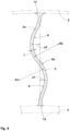
- FIG. 3 is a cross-sectional view taken along a line A-A in FIG. 2 .
- each spoke plate 5 of the present embodiment has a first end portion 6 which extends in the tire radial direction on one end side in the tire axial direction, and a second end portion 7 which extends in the tire radial direction on the other end side in the tire axial direction.
- each spoke plate 5 of the present embodiment has a spoke width w measured along a surface 5a of the spoke plate 5 from the first end portion 6 to the second end portion 7 at the same position in the tire radial direction.
- each spoke plate 5 is preferably smaller than a width W1 of the hub 3 and a width W2 of the tread ring 2. Such a spoke plate 5 serves to achieve weight reduction and can improve the low fuel consumption performance of the airless tire 1.
- FIG. 4 is an end view of the spoke plate 5 as viewed in the direction of the spoke width w. As shown in FIG. 3 and FIG. 4 , each spoke plate 5 of the present embodiment has a spoke thickness t orthogonal to the spoke width w and the surface 5a of the spoke plate 5.
- Each spoke plate 5 of the present embodiment includes a first curved portion 8 which is curved so as to project to one side in the tire circumferential direction on the hub 3 side, and a second curved portion 9 which is curved so as to project to the other side in the tire circumferential direction on the tread ring 2 side, as viewed in the direction of the spoke width w.
- a spoke plate 5 can improve the ride comfort of the airless tire 1 by the first curved portion 8 and the second curved portion 9.
- An amplitude a1 of the first curved portion 8 and an amplitude a2 of the second curved portion 9 of the present embodiment are different from each other.
- Such a spoke plate 5 can limit the direction of deformation occurring when large compressive force is applied to the spoke plate 5, such as when passing through a step, to the side where a curved portion having a larger amplitude, out of the first curved portion 8 and the second curved portion 9, is present. Accordingly, even when passing through a step, the spoke 4 can suppress contact between the spoke plates 5 adjacent to each other in the tire circumferential direction due to deformation. Therefore, the airless tire 1 according to the present embodiment can suppress damage to the spoke plates 5 to improve durability.
- of the difference between the amplitude a1 of the first curved portion 8 and the amplitude a2 of the second curved portion 9 is 1 to 3 mm.
- of the difference is not less than 1 mm, the direction of deformation occurring when large compressive force is applied to the spoke plate 5 can be reliably limited to the side where the curved portion having a larger amplitude is present.
- of the difference is not greater than 3 mm, strain occurring on the side where the curved portion having a larger amplitude is present can be reduced.
- the amplitude a2 of the second curved portion 9 is preferably larger than the amplitude a1 of the first curved portion 8.
- the amplitude a2 of the second curved portion 9 of the present embodiment is larger than the amplitude a1 of the first curved portion 8 by 1 to 3 mm.
- Such a spoke plate 5 has a good vibration absorbing effect by increasing the deformation of the second curved portion 9 which is located on the outer side in the tire radial direction, and can improve the ride comfort of the airless tire 1.
- a radius of curvature R2 of the second curved portion 9 is equal to a radius of curvature R1 of the first curved portion 8.
- Such a spoke plate 5 can limit the direction of deformation occurring when compressive force is applied thereto, to the direction based on amplitude.
- the spoke plate 5 can distribute strain occurring when compressive force is applied thereto, to the first curved portion 8 and the second curved portion 9, and can further improve the durability of the airless tire 1.
- the amplitude a1 of the first curved portion 8 of the present embodiment is uniform in the entire range of the spoke width w.
- the amplitude a2 of the second curved portion 9 of the present embodiment is uniform in the entire range of the spoke width w.
- Such a spoke plate 5 can distribute strain occurring when compressive force is applied thereto, in the direction of the spoke width w, and can further improve the durability of the airless tire 1.
- the tread ring 2 is formed of, for example, an elastic body such as rubber in a cylindrical shape.
- the tread ring 2 preferably has a plurality of grooves 10 formed on the ground-contact surface 2a which comes into contact with a road surface during running.
- the ground-contact surface 2a is not limited to such a mode, and, for example, the ground-contact surface 2a may have a block shape, or a plurality of recesses may be formed thereon.
- the hub 3 is formed of, for example, an inelastic body such as metal.
- the hub 3 preferably includes the disk-shaped fixed portion 3a which is fixed to an axle, and a cylindrical portion 3b which is connected to the spoke 4.
- the fixed portion 3a of the hub 3 has, for example, a plurality of fixing holes formed therein.
- the fixed portion 3a of the hub 3 is not limited to such a mode, and may be, for example, attachable to a dedicated axle through one-touch operation.
- the spoke 4 is formed from, for example, a polymer material having elasticity.
- the polymer material is preferably selected from a single elastomer, a composite elastomer containing two or more elastomers, and a fiber-containing elastomer.
- Such a spoke 4 has excellent balance between weight reduction, flexibility, and strength, and serves to improve the low fuel consumption performance, the ride comfort, and the durability of the airless tire 1 in a well-balanced manner.
- the spoke 4 of the present embodiment includes the plurality of spoke plates 5, an inner cylindrical portion 11 which is connected to the hub 3, and an outer cylindrical portion 12 which is connected to the tread ring 2. Accordingly, each spoke plate 5 is indirectly connected to the tread ring 2 and the hub 3.
- Such a spoke 4 can be firmly connected to the hub 3 and the tread ring 2 and can improve the durability of the airless tire 1.
- the inner cylindrical portion 11 and the outer cylindrical portion 12 may be omitted, and each spoke plate 5 may be directly connected to the tread ring 2 and the hub 3.
- each spoke plate 5 of the present embodiment includes an inner end portion 13 which is an end portion on the hub 3 side, and an outer end portion 14 which is an end portion on the tread ring 2 side.
- the inner end portion 13 is integrally formed with the inner cylindrical portion 11 via curved surface portions 5b.
- the outer end portion 14 is integrally formed with the outer cylindrical portion 12 via curved surface portions 5b.
- each spoke plate 5 the inner end portion 13 and the outer end portion 14 are preferably connected to the tread ring 2 and the hub 3 via the curved surface portions 5b, respectively.
- Such curved surface portions 5b can reduce strain occurring in the inner end portion 13 and the outer end portion 14, and can further improve the durability of the airless tire 1.
- a center line 5c of the spoke thickness t in the inner end portion 13 of the present embodiment extends so as to be parallel to the tire radial direction.
- the center line 5c of the spoke thickness t in the outer end portion 14 of the present embodiment also extends so as to be parallel to the tire radial direction, similar to that in the inner end portion 13.
- Such a spoke plate 5 can reduce strain occurring when tensile force is applied thereto, and can further improve the durability of the airless tire 1.
- the center line 5c of the spoke thickness t in the inner end portion 13 and the center line 5c of the spoke thickness t in the outer end portion 14 are preferably located on the same straight line as viewed in the direction of the spoke width w.
- Such a spoke plate 5 can limit the direction of deformation occurring when compressive force is applied thereto, to the direction based on amplitude.
- such a spoke plate 5 can reduce strain occurring when compressive force is applied thereto, and can further improve the durability of the airless tire 1.
- the spoke plates 5 of the present embodiment include first spoke plates 5A which are disposed on one side in the tire axial direction, and second spoke plates 5B which are disposed on the other side in the tire axial direction.
- the first spoke plates 5A and the second spoke plates 5B are, for example, alternately disposed in the tire circumferential direction.
- Such spoke plates 5 can achieve both weight reduction and balance in the tire axial direction, and can achieve both desired low fuel consumption performance and desired steering stability of the airless tire 1.
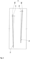
- FIG. 5 is a cross-sectional view taken along a line B-B in FIG. 2 .
- the inner end portion 13 of the present embodiment extends so as to be inclined relative to the tire axial direction.
- the outer end portion 14 preferably extends so as to be inclined relative to the tire axial direction in the same direction as the inner end portion 13.
- Inclination angles of the inner end portion 13 and the outer end portion 14 with respect to the tire axial direction are preferably 2 to 10°.
- the inclination angles are not less than 2°, the stiffness in the tire circumferential direction can be improved, and the durability of the airless tire 1 can be improved.
- the inclination angles are not greater than 10°, excessive stiffness in the tire circumferential direction can be suppressed, and the ride comfort of the airless tire 1 can be improved.
- each first spoke plate 5A and the inner end portion 13 of each second spoke plate 5B are preferably inclined relative to the tire axial direction in directions opposite to each other.
- Such a spoke 4 has good balance in the tire axial direction and can improve the ride comfort of the airless tire 1.
- An angle ⁇ 1 of the inner end portion 13 of each first spoke plate 5A with respect to the tire axial direction and an angle ⁇ 2 of the inner end portion 13 of each second spoke plate 5B with respect to the tire axial direction are preferably equal to each other.
- Such a spoke 4 has good balance in the tire axial direction and can improve the ride comfort of the airless tire 1.
- the angle ⁇ 1 of the inner end portion 13 of each first spoke plate 5A with respect to the tire axial direction and the angle ⁇ 2 of each inner end portion 13 of the second spoke plate 5B with respect to the tire axial direction may be, for example, different from each other.
- Airless tires having the basic structure in FIG. 1 to FIG. 5 were produced as test tires on the basis of specifications in Table 1, and were tested for durability.
- the main common specifications and the test method are as follows.
- each tire was caused to run under the conditions of a load of 3.8 kN and a speed of 60 km/h. After 24 hours, the running was stopped, and the degree of rubbing of the spoke was visually confirmed.
- the results are indexes with the result of a comparative example being regarded as 100. A higher value indicates that the rubbing of the spoke is smaller and that the durability is better.
Landscapes
- Engineering & Computer Science (AREA)
- Mechanical Engineering (AREA)
- Tires In General (AREA)
Claims (9)
- Luftloser Reifen (1), umfassend:einen Laufflächenring (2) mit einer Bodenkontaktfläche (2a);eine Nabe (3), die innerhalb des Laufflächenrings (2) in einer Reifenradialrichtung angeordnet und an einer Achse zu befestigen ist; undeine Speiche (4) zum Verbinden des Laufflächenrings (2) und der Nabe (3), wobeidie Speiche (4) eine Vielzahl von Speichenplatten (5) aufweist,jede der Speichenplatten (5) einen ersten Endabschnitt (6), der sich in der Reifenradialrichtung an einer Endseite in einer Reifenaxialrichtung erstreckt, einen zweiten Endabschnitt (7), der sich in der Reifenradialrichtung an einer anderen Endseite in der Reifenaxialrichtung erstreckt, eine Speichenbreite (w), die entlang einer Oberfläche (5a) der Speichenplatte (5) von dem ersten Endabschnitt (6) zu dem zweiten Endabschnitt (7) an der gleichen Position in der Reifenradialrichtung gemessen ist, und eine Speichendicke (t) orthogonal zu der Speichenbreite (w) und der Oberfläche (5a) der Speichenplatte (5) aufweist,jede der Speichenplatten (5) einen ersten gekrümmten Abschnitt (8) umfasst, der so gekrümmt ist, dass er zu einer Seite in einer Reifenumfangsrichtung auf der Seite der Nabe (3) vorsteht, und einen zweiten gekrümmten Abschnitt (9), der so gekrümmt ist, dass er zu einer anderen Seite in der Reifenumfangsrichtung auf der Seite des Laufflächenrings (2) vorsteht, wie in einer Richtung der Speichenbreite (w) gesehen, undeine Amplitude (a1) des ersten gekrümmten Abschnitts (8) zu einer Bezugslinie zwischen einem radialen Ende der Speichenplatte (5) in einem inneren Endabschnitt (13) der Speichenplatte (5), der ein Endabschnitt auf der Nabenseite ist, und dem anderen radialen Ende der Speichenplatte (5) in einem äußeren Endabschnitt (14) der Speichenplatte (5), der ein Endabschnitt auf der Laufflächenringseite ist, und eine Amplitude (a2) des zweiten gekrümmten Abschnitts (9) zu der Bezugslinie voneinander verschieden sind,dadurch gekennzeichnet, dass ein Krümmungsradius (R2) des zweiten gekrümmten Abschnitts (9) gleich einem Krümmungsradius (R1) des ersten gekrümmten Abschnitts (8) ist.
- Luftloser Reifen (1) nach Anspruch 1, wobeidie Amplitude (a1) des ersten gekrümmten Abschnitts (8) in einem gesamten Bereich der Speichenbreite (w) gleichmäßig ist, unddie Amplitude (a2) des zweiten gekrümmten Abschnitts (9) über den gesamten Bereich der Speichenbreite (w) gleichmäßig ist.
- Luftloser Reifen (1) nach Anspruch 1, wobei die Amplitude (a2) des zweiten gekrümmten Abschnitts (9) größer als die Amplitude (a1) des ersten gekrümmten Abschnitts (8) ist.
- Luftloser Reifen (1) nach einem der Ansprüche 1 bis 3, wobei eine Mittellinie (5c) der Speichendicke (t) in dem inneren Endabschnitt (13) und die Mittellinie (5c) der Speichendicke (t) in dem äußeren Endabschnitt (14) sich jeweils so erstrecken, dass sie an einem inneren Ende in dem inneren Endabschnitt (13) und an einem äußeren Ende in dem äußeren Endabschnitt (14) parallel zu der Reifenradialrichtung sind.
- Luftloser Reifen (1) nach Anspruch 4, wobei die Mittellinie (5c) der Speichendicke (t) an dem inneren Ende in dem inneren Endabschnitt (13) und die Mittellinie (5c) der Speichendicke (t) an dem äußeren Ende in dem äußeren Endabschnitt (14), wie in Richtung der Speichenbreite (w) gesehen, auf der gleichen Geraden liegen.
- Luftloser Reifen (1) nach Anspruch 4 oder 5, wobeisich der innere Endabschnitt (13) so erstreckt, dass er in Bezug auf die Reifenaxialrichtung geneigt ist, undder äußere Endabschnitt (14) sich so erstreckt, dass er in Bezug auf die Reifenaxialrichtung in der gleichen Richtung wie der innere Endabschnitt (13) geneigt ist.
- Luftloser Reifen (1) nach einem der Ansprüche 1 bis 6, wobei jede der Speichenplatten (5) indirekt oder direkt mit dem Laufflächenring (2) und der Nabe (3) verbunden ist.
- Luftloser Reifen (1) nach einem der Ansprüche 1 bis 7, wobei die Speiche (4) aus einem Polymermaterial gebildet ist.
- Luftloser Reifen (1) nach Anspruch 8, wobei das Polymermaterial ausgewählt ist aus einem einzigen Elastomer, einem Verbundelastomer, das zwei oder mehr Elastomere enthält, und einem faserhaltigen Elastomer.
Applications Claiming Priority (1)
| Application Number | Priority Date | Filing Date | Title |
|---|---|---|---|
| JP2021024581A JP7615746B2 (ja) | 2021-02-18 | 2021-02-18 | エアレスタイヤ |
Publications (2)
| Publication Number | Publication Date |
|---|---|
| EP4046821A1 EP4046821A1 (de) | 2022-08-24 |
| EP4046821B1 true EP4046821B1 (de) | 2023-10-25 |
Family
ID=80447785
Family Applications (1)
| Application Number | Title | Priority Date | Filing Date |
|---|---|---|---|
| EP22156184.8A Active EP4046821B1 (de) | 2021-02-18 | 2022-02-10 | Luftloser reifen |
Country Status (2)
| Country | Link |
|---|---|
| EP (1) | EP4046821B1 (de) |
| JP (1) | JP7615746B2 (de) |
Families Citing this family (1)
| Publication number | Priority date | Publication date | Assignee | Title |
|---|---|---|---|---|
| KR20250054947A (ko) | 2023-10-17 | 2025-04-24 | 한국타이어앤테크놀로지 주식회사 | 탑-로딩 비 및 비대칭 탄성을 고려한 비공기입 타이어의 설계 방법 |
Family Cites Families (8)
| Publication number | Priority date | Publication date | Assignee | Title |
|---|---|---|---|---|
| US8833864B2 (en) * | 2012-10-29 | 2014-09-16 | Karsten Manufacturing Corporation | Collapsible wheels and methods of making collapsible wheels |
| JP5930941B2 (ja) * | 2012-10-31 | 2016-06-08 | 株式会社ブリヂストン | 非空気入りタイヤ |
| JP6383294B2 (ja) * | 2015-01-13 | 2018-08-29 | 住友ゴム工業株式会社 | エアレスタイヤ |
| CN108136835B (zh) * | 2015-10-09 | 2019-11-22 | 株式会社普利司通 | 非充气轮胎 |
| US10696096B2 (en) * | 2015-12-08 | 2020-06-30 | The Goodyear Tire & Rubber Company | Non-pneumatic tire |
| KR101841655B1 (ko) * | 2016-09-01 | 2018-03-23 | 금호타이어 주식회사 | 비공기입 타이어 |
| JP7180427B2 (ja) * | 2019-02-06 | 2022-11-30 | 住友ゴム工業株式会社 | エアレスタイヤ |
| CN212446976U (zh) * | 2020-06-17 | 2021-02-02 | 青岛励扬橡胶科技有限公司 | 一种免充气轮胎 |
-
2021
- 2021-02-18 JP JP2021024581A patent/JP7615746B2/ja active Active
-
2022
- 2022-02-10 EP EP22156184.8A patent/EP4046821B1/de active Active
Also Published As
| Publication number | Publication date |
|---|---|
| JP7615746B2 (ja) | 2025-01-17 |
| JP2022126478A (ja) | 2022-08-30 |
| EP4046821A1 (de) | 2022-08-24 |
Similar Documents
| Publication | Publication Date | Title |
|---|---|---|
| US10406861B2 (en) | Airless tire | |
| US9487052B1 (en) | Airless tire construction having multiple layers | |
| EP2305489B1 (de) | Luftloser reifen | |
| EP0353006B1 (de) | Elastischer Reifen | |
| EP3446887B1 (de) | Luftloser reifen | |
| US10308075B2 (en) | Pneumatic tire | |
| JP6964470B2 (ja) | 非空気圧タイヤ | |
| US20230219366A1 (en) | Non-pneumatic tire having support structure with stress-concentration reduction features | |
| EP4046821B1 (de) | Luftloser reifen | |
| EP4019277B1 (de) | Luftloser reifen | |
| EP4046823B1 (de) | Luftloser reifen | |
| EP4046822B1 (de) | Luftloser reifen | |
| EP3798022A1 (de) | Nicht-pneumatischer reifen mit strukturverstärkung im laufflächenabschnitt | |
| JP2013018427A (ja) | 非空気圧タイヤ | |
| JP2023015874A (ja) | エアレスタイヤ | |
| JP7567266B2 (ja) | エアレスタイヤ | |
| US20250353329A1 (en) | Leaf spring support for spoke structure for non-pneumatic tire | |
| EP4393721B1 (de) | Luftloser reifen | |
| JP7687055B2 (ja) | エアレスタイヤ | |
| WO2025050198A1 (en) | Non-pneumatic suspension tire | |
| EP1717062A1 (de) | Elastisches rad und herstellungsverfahren dafür | |
| EP4532224A1 (de) | Selbsttragende speichenstruktur für nichtpneumatischen reifen | |
| JP2023079445A (ja) | 非空気圧タイヤ | |
| JP2008137645A (ja) | 支持体および空気入りランフラットタイヤ |
Legal Events
| Date | Code | Title | Description |
|---|---|---|---|
| PUAI | Public reference made under article 153(3) epc to a published international application that has entered the european phase |
Free format text: ORIGINAL CODE: 0009012 |
|
| STAA | Information on the status of an ep patent application or granted ep patent |
Free format text: STATUS: THE APPLICATION HAS BEEN PUBLISHED |
|
| AK | Designated contracting states |
Kind code of ref document: A1 Designated state(s): AL AT BE BG CH CY CZ DE DK EE ES FI FR GB GR HR HU IE IS IT LI LT LU LV MC MK MT NL NO PL PT RO RS SE SI SK SM TR |
|
| STAA | Information on the status of an ep patent application or granted ep patent |
Free format text: STATUS: REQUEST FOR EXAMINATION WAS MADE |
|
| 17P | Request for examination filed |
Effective date: 20221209 |
|
| RBV | Designated contracting states (corrected) |
Designated state(s): AL AT BE BG CH CY CZ DE DK EE ES FI FR GB GR HR HU IE IS IT LI LT LU LV MC MK MT NL NO PL PT RO RS SE SI SK SM TR |
|
| GRAP | Despatch of communication of intention to grant a patent |
Free format text: ORIGINAL CODE: EPIDOSNIGR1 |
|
| STAA | Information on the status of an ep patent application or granted ep patent |
Free format text: STATUS: GRANT OF PATENT IS INTENDED |
|
| INTG | Intention to grant announced |
Effective date: 20230509 |
|
| GRAS | Grant fee paid |
Free format text: ORIGINAL CODE: EPIDOSNIGR3 |
|
| GRAA | (expected) grant |
Free format text: ORIGINAL CODE: 0009210 |
|
| STAA | Information on the status of an ep patent application or granted ep patent |
Free format text: STATUS: THE PATENT HAS BEEN GRANTED |
|
| AK | Designated contracting states |
Kind code of ref document: B1 Designated state(s): AL AT BE BG CH CY CZ DE DK EE ES FI FR GB GR HR HU IE IS IT LI LT LU LV MC MK MT NL NO PL PT RO RS SE SI SK SM TR |
|
| REG | Reference to a national code |
Ref country code: GB Ref legal event code: FG4D |
|
| REG | Reference to a national code |
Ref country code: CH Ref legal event code: EP |
|
| REG | Reference to a national code |
Ref country code: DE Ref legal event code: R096 Ref document number: 602022000744 Country of ref document: DE |
|
| REG | Reference to a national code |
Ref country code: IE Ref legal event code: FG4D |
|
| REG | Reference to a national code |
Ref country code: LT Ref legal event code: MG9D |
|
| REG | Reference to a national code |
Ref country code: NL Ref legal event code: MP Effective date: 20231025 |
|
| REG | Reference to a national code |
Ref country code: AT Ref legal event code: MK05 Ref document number: 1624321 Country of ref document: AT Kind code of ref document: T Effective date: 20231025 |
|
| PG25 | Lapsed in a contracting state [announced via postgrant information from national office to epo] |
Ref country code: NL Free format text: LAPSE BECAUSE OF FAILURE TO SUBMIT A TRANSLATION OF THE DESCRIPTION OR TO PAY THE FEE WITHIN THE PRESCRIBED TIME-LIMIT Effective date: 20231025 |
|
| PG25 | Lapsed in a contracting state [announced via postgrant information from national office to epo] |
Ref country code: GR Free format text: LAPSE BECAUSE OF FAILURE TO SUBMIT A TRANSLATION OF THE DESCRIPTION OR TO PAY THE FEE WITHIN THE PRESCRIBED TIME-LIMIT Effective date: 20240126 |
|
| PG25 | Lapsed in a contracting state [announced via postgrant information from national office to epo] |
Ref country code: IS Free format text: LAPSE BECAUSE OF FAILURE TO SUBMIT A TRANSLATION OF THE DESCRIPTION OR TO PAY THE FEE WITHIN THE PRESCRIBED TIME-LIMIT Effective date: 20240225 |
|
| PG25 | Lapsed in a contracting state [announced via postgrant information from national office to epo] |
Ref country code: LT Free format text: LAPSE BECAUSE OF FAILURE TO SUBMIT A TRANSLATION OF THE DESCRIPTION OR TO PAY THE FEE WITHIN THE PRESCRIBED TIME-LIMIT Effective date: 20231025 |
|
| PG25 | Lapsed in a contracting state [announced via postgrant information from national office to epo] |
Ref country code: AT Free format text: LAPSE BECAUSE OF FAILURE TO SUBMIT A TRANSLATION OF THE DESCRIPTION OR TO PAY THE FEE WITHIN THE PRESCRIBED TIME-LIMIT Effective date: 20231025 |
|
| PG25 | Lapsed in a contracting state [announced via postgrant information from national office to epo] |
Ref country code: ES Free format text: LAPSE BECAUSE OF FAILURE TO SUBMIT A TRANSLATION OF THE DESCRIPTION OR TO PAY THE FEE WITHIN THE PRESCRIBED TIME-LIMIT Effective date: 20231025 |
|
| PG25 | Lapsed in a contracting state [announced via postgrant information from national office to epo] |
Ref country code: LT Free format text: LAPSE BECAUSE OF FAILURE TO SUBMIT A TRANSLATION OF THE DESCRIPTION OR TO PAY THE FEE WITHIN THE PRESCRIBED TIME-LIMIT Effective date: 20231025 Ref country code: IS Free format text: LAPSE BECAUSE OF FAILURE TO SUBMIT A TRANSLATION OF THE DESCRIPTION OR TO PAY THE FEE WITHIN THE PRESCRIBED TIME-LIMIT Effective date: 20240225 Ref country code: GR Free format text: LAPSE BECAUSE OF FAILURE TO SUBMIT A TRANSLATION OF THE DESCRIPTION OR TO PAY THE FEE WITHIN THE PRESCRIBED TIME-LIMIT Effective date: 20240126 Ref country code: ES Free format text: LAPSE BECAUSE OF FAILURE TO SUBMIT A TRANSLATION OF THE DESCRIPTION OR TO PAY THE FEE WITHIN THE PRESCRIBED TIME-LIMIT Effective date: 20231025 Ref country code: BG Free format text: LAPSE BECAUSE OF FAILURE TO SUBMIT A TRANSLATION OF THE DESCRIPTION OR TO PAY THE FEE WITHIN THE PRESCRIBED TIME-LIMIT Effective date: 20240125 Ref country code: AT Free format text: LAPSE BECAUSE OF FAILURE TO SUBMIT A TRANSLATION OF THE DESCRIPTION OR TO PAY THE FEE WITHIN THE PRESCRIBED TIME-LIMIT Effective date: 20231025 Ref country code: PT Free format text: LAPSE BECAUSE OF FAILURE TO SUBMIT A TRANSLATION OF THE DESCRIPTION OR TO PAY THE FEE WITHIN THE PRESCRIBED TIME-LIMIT Effective date: 20240226 |
|
| PG25 | Lapsed in a contracting state [announced via postgrant information from national office to epo] |
Ref country code: SE Free format text: LAPSE BECAUSE OF FAILURE TO SUBMIT A TRANSLATION OF THE DESCRIPTION OR TO PAY THE FEE WITHIN THE PRESCRIBED TIME-LIMIT Effective date: 20231025 Ref country code: RS Free format text: LAPSE BECAUSE OF FAILURE TO SUBMIT A TRANSLATION OF THE DESCRIPTION OR TO PAY THE FEE WITHIN THE PRESCRIBED TIME-LIMIT Effective date: 20231025 Ref country code: PL Free format text: LAPSE BECAUSE OF FAILURE TO SUBMIT A TRANSLATION OF THE DESCRIPTION OR TO PAY THE FEE WITHIN THE PRESCRIBED TIME-LIMIT Effective date: 20231025 Ref country code: NO Free format text: LAPSE BECAUSE OF FAILURE TO SUBMIT A TRANSLATION OF THE DESCRIPTION OR TO PAY THE FEE WITHIN THE PRESCRIBED TIME-LIMIT Effective date: 20240125 Ref country code: LV Free format text: LAPSE BECAUSE OF FAILURE TO SUBMIT A TRANSLATION OF THE DESCRIPTION OR TO PAY THE FEE WITHIN THE PRESCRIBED TIME-LIMIT Effective date: 20231025 Ref country code: HR Free format text: LAPSE BECAUSE OF FAILURE TO SUBMIT A TRANSLATION OF THE DESCRIPTION OR TO PAY THE FEE WITHIN THE PRESCRIBED TIME-LIMIT Effective date: 20231025 |
|
| PG25 | Lapsed in a contracting state [announced via postgrant information from national office to epo] |
Ref country code: DK Free format text: LAPSE BECAUSE OF FAILURE TO SUBMIT A TRANSLATION OF THE DESCRIPTION OR TO PAY THE FEE WITHIN THE PRESCRIBED TIME-LIMIT Effective date: 20231025 |
|
| PG25 | Lapsed in a contracting state [announced via postgrant information from national office to epo] |
Ref country code: CZ Free format text: LAPSE BECAUSE OF FAILURE TO SUBMIT A TRANSLATION OF THE DESCRIPTION OR TO PAY THE FEE WITHIN THE PRESCRIBED TIME-LIMIT Effective date: 20231025 |
|
| REG | Reference to a national code |
Ref country code: DE Ref legal event code: R097 Ref document number: 602022000744 Country of ref document: DE |
|
| PG25 | Lapsed in a contracting state [announced via postgrant information from national office to epo] |
Ref country code: SK Free format text: LAPSE BECAUSE OF FAILURE TO SUBMIT A TRANSLATION OF THE DESCRIPTION OR TO PAY THE FEE WITHIN THE PRESCRIBED TIME-LIMIT Effective date: 20231025 |
|
| PG25 | Lapsed in a contracting state [announced via postgrant information from national office to epo] |
Ref country code: SM Free format text: LAPSE BECAUSE OF FAILURE TO SUBMIT A TRANSLATION OF THE DESCRIPTION OR TO PAY THE FEE WITHIN THE PRESCRIBED TIME-LIMIT Effective date: 20231025 Ref country code: SK Free format text: LAPSE BECAUSE OF FAILURE TO SUBMIT A TRANSLATION OF THE DESCRIPTION OR TO PAY THE FEE WITHIN THE PRESCRIBED TIME-LIMIT Effective date: 20231025 Ref country code: RO Free format text: LAPSE BECAUSE OF FAILURE TO SUBMIT A TRANSLATION OF THE DESCRIPTION OR TO PAY THE FEE WITHIN THE PRESCRIBED TIME-LIMIT Effective date: 20231025 Ref country code: IT Free format text: LAPSE BECAUSE OF FAILURE TO SUBMIT A TRANSLATION OF THE DESCRIPTION OR TO PAY THE FEE WITHIN THE PRESCRIBED TIME-LIMIT Effective date: 20231025 Ref country code: EE Free format text: LAPSE BECAUSE OF FAILURE TO SUBMIT A TRANSLATION OF THE DESCRIPTION OR TO PAY THE FEE WITHIN THE PRESCRIBED TIME-LIMIT Effective date: 20231025 Ref country code: DK Free format text: LAPSE BECAUSE OF FAILURE TO SUBMIT A TRANSLATION OF THE DESCRIPTION OR TO PAY THE FEE WITHIN THE PRESCRIBED TIME-LIMIT Effective date: 20231025 Ref country code: CZ Free format text: LAPSE BECAUSE OF FAILURE TO SUBMIT A TRANSLATION OF THE DESCRIPTION OR TO PAY THE FEE WITHIN THE PRESCRIBED TIME-LIMIT Effective date: 20231025 |
|
| PLBE | No opposition filed within time limit |
Free format text: ORIGINAL CODE: 0009261 |
|
| STAA | Information on the status of an ep patent application or granted ep patent |
Free format text: STATUS: NO OPPOSITION FILED WITHIN TIME LIMIT |
|
| PG25 | Lapsed in a contracting state [announced via postgrant information from national office to epo] |
Ref country code: MC Free format text: LAPSE BECAUSE OF FAILURE TO SUBMIT A TRANSLATION OF THE DESCRIPTION OR TO PAY THE FEE WITHIN THE PRESCRIBED TIME-LIMIT Effective date: 20231025 |
|
| 26N | No opposition filed |
Effective date: 20240726 |
|
| PG25 | Lapsed in a contracting state [announced via postgrant information from national office to epo] |
Ref country code: LU Free format text: LAPSE BECAUSE OF NON-PAYMENT OF DUE FEES Effective date: 20240210 |
|
| PG25 | Lapsed in a contracting state [announced via postgrant information from national office to epo] |
Ref country code: SI Free format text: LAPSE BECAUSE OF FAILURE TO SUBMIT A TRANSLATION OF THE DESCRIPTION OR TO PAY THE FEE WITHIN THE PRESCRIBED TIME-LIMIT Effective date: 20231025 |
|
| PG25 | Lapsed in a contracting state [announced via postgrant information from national office to epo] |
Ref country code: SI Free format text: LAPSE BECAUSE OF FAILURE TO SUBMIT A TRANSLATION OF THE DESCRIPTION OR TO PAY THE FEE WITHIN THE PRESCRIBED TIME-LIMIT Effective date: 20231025 Ref country code: LU Free format text: LAPSE BECAUSE OF NON-PAYMENT OF DUE FEES Effective date: 20240210 |
|
| P01 | Opt-out of the competence of the unified patent court (upc) registered |
Free format text: CASE NUMBER: UPC_APP_117797/2023 Effective date: 20230510 |
|
| REG | Reference to a national code |
Ref country code: BE Ref legal event code: MM Effective date: 20240229 |
|
| PG25 | Lapsed in a contracting state [announced via postgrant information from national office to epo] |
Ref country code: BE Free format text: LAPSE BECAUSE OF NON-PAYMENT OF DUE FEES Effective date: 20240229 |
|
| PG25 | Lapsed in a contracting state [announced via postgrant information from national office to epo] |
Ref country code: IE Free format text: LAPSE BECAUSE OF NON-PAYMENT OF DUE FEES Effective date: 20240210 |
|
| PG25 | Lapsed in a contracting state [announced via postgrant information from national office to epo] |
Ref country code: IE Free format text: LAPSE BECAUSE OF NON-PAYMENT OF DUE FEES Effective date: 20240210 Ref country code: BE Free format text: LAPSE BECAUSE OF NON-PAYMENT OF DUE FEES Effective date: 20240229 |
|
| PG25 | Lapsed in a contracting state [announced via postgrant information from national office to epo] |
Ref country code: CY Free format text: LAPSE BECAUSE OF FAILURE TO SUBMIT A TRANSLATION OF THE DESCRIPTION OR TO PAY THE FEE WITHIN THE PRESCRIBED TIME-LIMIT; INVALID AB INITIO Effective date: 20220210 |
|
| REG | Reference to a national code |
Ref country code: CH Ref legal event code: PL |
|
| PG25 | Lapsed in a contracting state [announced via postgrant information from national office to epo] |
Ref country code: FI Free format text: LAPSE BECAUSE OF FAILURE TO SUBMIT A TRANSLATION OF THE DESCRIPTION OR TO PAY THE FEE WITHIN THE PRESCRIBED TIME-LIMIT Effective date: 20231025 |
|
| PG25 | Lapsed in a contracting state [announced via postgrant information from national office to epo] |
Ref country code: CH Free format text: LAPSE BECAUSE OF NON-PAYMENT OF DUE FEES Effective date: 20250228 |
|
| PG25 | Lapsed in a contracting state [announced via postgrant information from national office to epo] |
Ref country code: TR Free format text: LAPSE BECAUSE OF FAILURE TO SUBMIT A TRANSLATION OF THE DESCRIPTION OR TO PAY THE FEE WITHIN THE PRESCRIBED TIME-LIMIT Effective date: 20231025 |
|
| PGFP | Annual fee paid to national office [announced via postgrant information from national office to epo] |
Ref country code: FR Payment date: 20251231 Year of fee payment: 5 |
|
| PGFP | Annual fee paid to national office [announced via postgrant information from national office to epo] |
Ref country code: DE Payment date: 20251230 Year of fee payment: 5 |