EP4046672B1 - Autoinjektor - Google Patents
Autoinjektor Download PDFInfo
- Publication number
- EP4046672B1 EP4046672B1 EP22167357.7A EP22167357A EP4046672B1 EP 4046672 B1 EP4046672 B1 EP 4046672B1 EP 22167357 A EP22167357 A EP 22167357A EP 4046672 B1 EP4046672 B1 EP 4046672B1
- Authority
- EP
- European Patent Office
- Prior art keywords
- case
- plunger
- autoinjector
- needle
- shroud
- Prior art date
- Legal status (The legal status is an assumption and is not a legal conclusion. Google has not performed a legal analysis and makes no representation as to the accuracy of the status listed.)
- Active
Links
Images


Classifications
-
- A—HUMAN NECESSITIES
- A61—MEDICAL OR VETERINARY SCIENCE; HYGIENE
- A61M—DEVICES FOR INTRODUCING MEDIA INTO, OR ONTO, THE BODY; DEVICES FOR TRANSDUCING BODY MEDIA OR FOR TAKING MEDIA FROM THE BODY; DEVICES FOR PRODUCING OR ENDING SLEEP OR STUPOR
- A61M5/00—Devices for bringing media into the body in a subcutaneous, intra-vascular or intramuscular way; Accessories therefor, e.g. filling or cleaning devices, arm-rests
- A61M5/178—Syringes
- A61M5/20—Automatic syringes, e.g. with automatically actuated piston rod, with automatic needle injection, filling automatically
-
- A—HUMAN NECESSITIES
- A61—MEDICAL OR VETERINARY SCIENCE; HYGIENE
- A61M—DEVICES FOR INTRODUCING MEDIA INTO, OR ONTO, THE BODY; DEVICES FOR TRANSDUCING BODY MEDIA OR FOR TAKING MEDIA FROM THE BODY; DEVICES FOR PRODUCING OR ENDING SLEEP OR STUPOR
- A61M5/00—Devices for bringing media into the body in a subcutaneous, intra-vascular or intramuscular way; Accessories therefor, e.g. filling or cleaning devices, arm-rests
- A61M5/178—Syringes
- A61M5/31—Details
- A61M5/315—Pistons; Piston-rods; Guiding, blocking or restricting the movement of the rod or piston; Appliances on the rod for facilitating dosing ; Dosing mechanisms
- A61M5/31565—Administration mechanisms, i.e. constructional features, modes of administering a dose
- A61M5/31576—Constructional features or modes of drive mechanisms for piston rods
- A61M5/31583—Constructional features or modes of drive mechanisms for piston rods based on rotational translation, i.e. movement of piston rod is caused by relative rotation between the user activated actuator and the piston rod
- A61M5/31586—Constructional features or modes of drive mechanisms for piston rods based on rotational translation, i.e. movement of piston rod is caused by relative rotation between the user activated actuator and the piston rod performed by rotationally moving or pivoted actuator, e.g. an injection lever or handle
-
- A—HUMAN NECESSITIES
- A61—MEDICAL OR VETERINARY SCIENCE; HYGIENE
- A61M—DEVICES FOR INTRODUCING MEDIA INTO, OR ONTO, THE BODY; DEVICES FOR TRANSDUCING BODY MEDIA OR FOR TAKING MEDIA FROM THE BODY; DEVICES FOR PRODUCING OR ENDING SLEEP OR STUPOR
- A61M5/00—Devices for bringing media into the body in a subcutaneous, intra-vascular or intramuscular way; Accessories therefor, e.g. filling or cleaning devices, arm-rests
- A61M5/178—Syringes
- A61M5/20—Automatic syringes, e.g. with automatically actuated piston rod, with automatic needle injection, filling automatically
- A61M5/2033—Spring-loaded one-shot injectors with or without automatic needle insertion
-
- A—HUMAN NECESSITIES
- A61—MEDICAL OR VETERINARY SCIENCE; HYGIENE
- A61M—DEVICES FOR INTRODUCING MEDIA INTO, OR ONTO, THE BODY; DEVICES FOR TRANSDUCING BODY MEDIA OR FOR TAKING MEDIA FROM THE BODY; DEVICES FOR PRODUCING OR ENDING SLEEP OR STUPOR
- A61M5/00—Devices for bringing media into the body in a subcutaneous, intra-vascular or intramuscular way; Accessories therefor, e.g. filling or cleaning devices, arm-rests
- A61M5/178—Syringes
- A61M5/31—Details
- A61M5/32—Needles; Details of needles pertaining to their connection with syringe or hub; Accessories for bringing the needle into, or holding the needle on, the body; Devices for protection of needles
- A61M5/3202—Devices for protection of the needle before use, e.g. caps
-
- A—HUMAN NECESSITIES
- A61—MEDICAL OR VETERINARY SCIENCE; HYGIENE
- A61M—DEVICES FOR INTRODUCING MEDIA INTO, OR ONTO, THE BODY; DEVICES FOR TRANSDUCING BODY MEDIA OR FOR TAKING MEDIA FROM THE BODY; DEVICES FOR PRODUCING OR ENDING SLEEP OR STUPOR
- A61M5/00—Devices for bringing media into the body in a subcutaneous, intra-vascular or intramuscular way; Accessories therefor, e.g. filling or cleaning devices, arm-rests
- A61M5/178—Syringes
- A61M5/20—Automatic syringes, e.g. with automatically actuated piston rod, with automatic needle injection, filling automatically
- A61M2005/2006—Having specific accessories
- A61M2005/2013—Having specific accessories triggering of discharging means by contact of injector with patient body
-
- A—HUMAN NECESSITIES
- A61—MEDICAL OR VETERINARY SCIENCE; HYGIENE
- A61M—DEVICES FOR INTRODUCING MEDIA INTO, OR ONTO, THE BODY; DEVICES FOR TRANSDUCING BODY MEDIA OR FOR TAKING MEDIA FROM THE BODY; DEVICES FOR PRODUCING OR ENDING SLEEP OR STUPOR
- A61M5/00—Devices for bringing media into the body in a subcutaneous, intra-vascular or intramuscular way; Accessories therefor, e.g. filling or cleaning devices, arm-rests
- A61M5/178—Syringes
- A61M5/31—Details
- A61M5/32—Needles; Details of needles pertaining to their connection with syringe or hub; Accessories for bringing the needle into, or holding the needle on, the body; Devices for protection of needles
- A61M5/3205—Apparatus for removing or disposing of used needles or syringes, e.g. containers; Means for protection against accidental injuries from used needles
- A61M5/321—Means for protection against accidental injuries by used needles
- A61M5/3243—Means for protection against accidental injuries by used needles being axially-extensible, e.g. protective sleeves coaxially slidable on the syringe barrel
- A61M5/3245—Constructional features thereof, e.g. to improve manipulation or functioning
- A61M2005/3247—Means to impede repositioning of protection sleeve from needle covering to needle uncovering position
-
- A—HUMAN NECESSITIES
- A61—MEDICAL OR VETERINARY SCIENCE; HYGIENE
- A61M—DEVICES FOR INTRODUCING MEDIA INTO, OR ONTO, THE BODY; DEVICES FOR TRANSDUCING BODY MEDIA OR FOR TAKING MEDIA FROM THE BODY; DEVICES FOR PRODUCING OR ENDING SLEEP OR STUPOR
- A61M2205/00—General characteristics of the apparatus
- A61M2205/58—Means for facilitating use, e.g. by people with impaired vision
- A61M2205/581—Means for facilitating use, e.g. by people with impaired vision by audible feedback
-
- A—HUMAN NECESSITIES
- A61—MEDICAL OR VETERINARY SCIENCE; HYGIENE
- A61M—DEVICES FOR INTRODUCING MEDIA INTO, OR ONTO, THE BODY; DEVICES FOR TRANSDUCING BODY MEDIA OR FOR TAKING MEDIA FROM THE BODY; DEVICES FOR PRODUCING OR ENDING SLEEP OR STUPOR
- A61M2205/00—General characteristics of the apparatus
- A61M2205/58—Means for facilitating use, e.g. by people with impaired vision
- A61M2205/582—Means for facilitating use, e.g. by people with impaired vision by tactile feedback
-
- A—HUMAN NECESSITIES
- A61—MEDICAL OR VETERINARY SCIENCE; HYGIENE
- A61M—DEVICES FOR INTRODUCING MEDIA INTO, OR ONTO, THE BODY; DEVICES FOR TRANSDUCING BODY MEDIA OR FOR TAKING MEDIA FROM THE BODY; DEVICES FOR PRODUCING OR ENDING SLEEP OR STUPOR
- A61M2205/00—General characteristics of the apparatus
- A61M2205/58—Means for facilitating use, e.g. by people with impaired vision
- A61M2205/583—Means for facilitating use, e.g. by people with impaired vision by visual feedback
-
- A—HUMAN NECESSITIES
- A61—MEDICAL OR VETERINARY SCIENCE; HYGIENE
- A61M—DEVICES FOR INTRODUCING MEDIA INTO, OR ONTO, THE BODY; DEVICES FOR TRANSDUCING BODY MEDIA OR FOR TAKING MEDIA FROM THE BODY; DEVICES FOR PRODUCING OR ENDING SLEEP OR STUPOR
- A61M5/00—Devices for bringing media into the body in a subcutaneous, intra-vascular or intramuscular way; Accessories therefor, e.g. filling or cleaning devices, arm-rests
- A61M5/178—Syringes
- A61M5/31—Details
- A61M5/32—Needles; Details of needles pertaining to their connection with syringe or hub; Accessories for bringing the needle into, or holding the needle on, the body; Devices for protection of needles
- A61M5/3205—Apparatus for removing or disposing of used needles or syringes, e.g. containers; Means for protection against accidental injuries from used needles
- A61M5/321—Means for protection against accidental injuries by used needles
- A61M5/3243—Means for protection against accidental injuries by used needles being axially-extensible, e.g. protective sleeves coaxially slidable on the syringe barrel
- A61M5/326—Fully automatic sleeve extension, i.e. in which triggering of the sleeve does not require a deliberate action by the user
-
- A—HUMAN NECESSITIES
- A61—MEDICAL OR VETERINARY SCIENCE; HYGIENE
- A61M—DEVICES FOR INTRODUCING MEDIA INTO, OR ONTO, THE BODY; DEVICES FOR TRANSDUCING BODY MEDIA OR FOR TAKING MEDIA FROM THE BODY; DEVICES FOR PRODUCING OR ENDING SLEEP OR STUPOR
- A61M5/00—Devices for bringing media into the body in a subcutaneous, intra-vascular or intramuscular way; Accessories therefor, e.g. filling or cleaning devices, arm-rests
- A61M5/50—Devices for bringing media into the body in a subcutaneous, intra-vascular or intramuscular way; Accessories therefor, e.g. filling or cleaning devices, arm-rests having means for preventing re-use, or for indicating if defective, used, tampered with or unsterile
- A61M5/5086—Devices for bringing media into the body in a subcutaneous, intra-vascular or intramuscular way; Accessories therefor, e.g. filling or cleaning devices, arm-rests having means for preventing re-use, or for indicating if defective, used, tampered with or unsterile for indicating if defective, used, tampered with or unsterile
Definitions
- the invention relates to an autoinjector.
- Administering an injection is a process which presents a number of risks and challenges for users and healthcare professionals, both mental and physical.
- Injection devices typically fall into two categories - manual devices and autoinjectors.
- manual force is required to drive a medicament through a needle. This is typically done by some form of button / plunger that has to be continuously pressed during the injection.
- button / plunger that has to be continuously pressed during the injection.
- There are numerous disadvantages associated with this approach For example, if the button / plunger is released prematurely, the injection will stop and may not deliver an intended dose. Further, the force required to push the button / plunger may be too high (e.g., if the user is elderly or a child). And, aligning the injection device, administering the injection and keeping the injection device still during the injection may require dexterity which some patients (e.g., elderly patients, children, arthritic patients, etc.) may not have.
- Autoinjector devices aim to make self-injection easier for patients.
- a conventional autoinjector may provide the force for administering the injection by a spring, and trigger button or other mechanism may be used to activate the injection.
- Autoinjectors may be single-use or reusable devices.
- the autoinjector comprises, inter alia, a case adapted to hold a medicament container having a needle and the case including a rib, a needle shroud slidably disposed in the case and translatable between an extended position relative to the case in which the needle is covered and a retracted position relative to the case in which the needle (4) is exposed, and a plunger slidably disposed in the case.
- the plunger including a plunger boss adapted to abut the rib and the needle shroud when the needle shroud is in the extended position and disengage the rib when the needle shroud is in the retracted position to allow the plunger to translate axially relative to the case.
- a first shroud boss on the needle shroud abuts the plunger boss when the needle shroud is in the extended position.
- a second shroud boss on the needle shroud proximal of the first shroud boss abuts the plunger boss when the needle shroud is in the extended position.
- a resistance element is formed on the first shroud boss. The resistance element is adapted to engage the plunger boss as the needle shroud translates from the extended position to the retracted position.
- the resistance element includes at least one of a bump, a ramp, an abutment, a recess, a spring detent and a preloaded beam.
- a resilient shroud beam on the needle shroud is deflected by a resilient case backstop beam when the needle shroud translates from the retracted position to a second extended position distal relative to the case of the extended position.
- the resilient shroud beam abuts the resilient case backstop beam when the needle shroud is in the second extended position to prevent proximal movement of the needle shroud relative to the case.
- the resilient case backstop beam abuts the medicament container when the needle shroud is in the second extended position.
- the autoinjector further comprises a shroud spring biasing the needle shroud toward the extended position.
- the autoinjector further comprises a drive spring biasing the plunger relative to the case.
- the case includes a bayonet slot adapted to engage the plunger boss.
- the plunger boss partially disengages the bayonet slot when the plunger boss abuts the rib.
- the rib is angled with respect to a longitudinal axis of the case and imparts a rotational and an axial force on the plunger boss.
- the case includes a viewing window.
- the autoinjector further comprises a cap coupled to a protective needle sheath covering the needle.
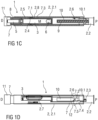
- FIGS 1A-D show an exemplary embodiment of an autoinjector 1 according to the present invention during assembly.
- an exemplary embodiment of the autoinjector 1 comprises a case 2 comprising a front case 2.1 and a rear case 2.2.
- the case 2 may comprise a single case.
- a cap 11 may be removably coupled to a distal end of the case 2.
- the case 2 may include a viewing window 2.7, which may be a transparent portion of the case 2 or a cut-out.
- a needle shroud 7 may be telescoped within the case 2.
- the case 2 is adapted to hold a medicament container, such as a syringe 3.
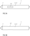
- the syringe 3 may be a pre-filled syringe and have a needle 4 (cf. fig. 3C ) arranged at a distal end.
- a protective needle sheath 5 may be removably coupled to the needle 4.
- a stopper 6 is arranged for sealing the syringe 3 proximally and for displacing a medicament M contained in the syringe 3 through the needle 4.
- the syringe 3 is held in a fixed position relative to the case 2 and supported at its proximal end therein.
- the medicament container may be a cartridge which includes the medicament M and engages a removable needle.
- the needle shroud 7 is slidably disposed in the case 2 and capable of moving proximally and distally relative to the case 2.
- the needle shroud 7 may be biased in the distal direction D relative to the case 2 by a shroud spring 8.
- a drive spring 9 (e.g., a compression spring) is arranged within a proximal part of the case 2.
- a plunger 10 serves for forwarding a force of the drive spring 9 to the stopper 6.
- the plunger 10 is hollow and the drive spring 9 is arranged within the plunger 10 biasing the plunger 10 in the distal direction D against the rear case 2.2.
- the plunger 10 comprises a plunger boss 10.1 being part of a plunger release mechanism 12 arranged for preventing release of the plunger 10 prior to depression of the needle shroud 7 against an injection site and for releasing the plunger 10 once the needle shroud 7 is depressed.
- the drive spring 9 is inserted into the plunger 10 and grounded proximally on the rear case 2.2, and the plunger 10 is pressed against the rear case 2.2, compressing the drive spring 9.
- the plunger 10 is rotated such that the plunger boss 10.1 engages a bayonet slot 2.3 formed in the case 2.
- the drive spring 9 may then be allowed to slightly expand and lock the plunger boss 10.1 within the bayonet slot 2.3.
- the plunger 10 can only be released from the bayonet slot 2.3 by axial translation in the proximal direction P relative to the rear case 2.2 and rotation relative to the rear case 2.2.
- the shroud spring 8 is inserted into the front case 2.1 and grounded proximally in the front case 2.1, and the needle shroud 7 is pressed against the front case 2.1, compressing the shroud spring 9.
- a resilient shroud beam 7.1 on the needle shroud 7 contacts a compliant case backstop beam 2.4 on a syringe support portion 2.5 of the case 2.
- the case backstop beam 2.4 is able to deflect in a radially inwards direction and the shroud beam 7.1 can pass the case backstop beam 2.4 in the proximal direction P.
- the syringe 3 is assembled into the front case 2.1 from the proximal direction P to the distal direction D.
- the syringe 3 may be inserted with the needle 4 and the protective needle sheath 5 attached.
- the needle 4 and/or the protective needle sheath 5 may be assembled to the syringe 3 after insertion of the syringe 3 into the front case 2.1.
- the case backstop beam 2.4 abuts the syringe 3 and, thus, cannot be deflected radially inward.
- the shroud backstop beam 7.1 must deflect radially outward around the case backstop beam 2.4.
- the assembled rear case 2.2, with the plunger 10 and the drive spring 9, may be coupled to the front case 2.1 after insertion of the syringe 3.
- the plunger boss 10.1 contacts an angled rib 2.6 on the front case 2.1, which applies axial (in the proximal direction P) and rotational forces to the plunger boss 10.1.
- the axial and rotational force applied to the plunger boss 10.1 causes the plunger 10 to move proximally and rotationally relative to the rear case 2.2, partially disengaging the bayonet slot 2.3.
- a first shroud boss 7.2 on the needle shroud 7 abuts the plunger boss 10.1, and the angled rib 2.6 and the first shroud boss 7.2 prevent the plunger boss 10.1 from fully disengaging the bayonet slot 2.3.
- a second shroud boss 7.4 abuts the plunger boss 10.1, thus limiting extension distally of the needle shroud 7 from the case 2.
- the plunger boss 10.1, the angled rib 2.6 and the first shroud boss 7.2 comprise a plunger release mechanism 12.
- the cap 11 is coupled to the protective needle sheath 5 after insertion of the syringe 3.
- the cap 11 may be arranged to engage the protective needle sheath 5 by a barb, snap-fit, friction, hooks, etc. such that the protective needle sheath 5 is moved axially in the distal direction D as the cap 11 moves axially in the distal direction D.
- the cap 11 may engage the needle shroud 7 and/or the case 2.
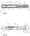
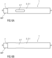
- Figures 2A and 2B are different side views of an exemplary embodiment of an assembled autoinjector 1 according to the present invention prior to use.
- Figure 2C is a longitudinal section of an exemplary embodiment of an assembled autoinjector 1 according to the present invention.
- Figure 2D is a semitransparent side view of an exemplary embodiment of an assembled autoinjector 1 according to the present invention.
- a sequence of operation of an exemplary embodiment of an assembled autoinjector 1 according to the present invention may be as follows: Prior to use, the autoinjector 1 is in the state as illustrated in figures 2A to 2D . If applicable, the user removes the autoinjector 1 from the packaging. The user may then examine the medicament M through the viewing window 2.7.
- the user removes the cap 11 pulling it in the distal direction D away from the case 2, thereby also removing the protective needle sheath 5.
- load exerted by pulling the cap 11 may be resolved by the case 2.
- the needle shroud 7 is in an extended position EP protruding from the case 2 in the distal direction D.
- the extended position EP is defined by the plunger boss 10.1 abutting the second shroud boss 7.4, thereby limiting movement of the needle shroud 7.4 relative to the case 2 in the distal direction D under the force of the shroud spring 8.
- the autoinjector 1 is pressed against the injection site with the needle shroud 7 impacting the injection site and thereby moving the needle shroud 7 from the extended position EP to a retracted position RP against the bias of the shroud spring 8.
- the plunger boss 10.1 rides along the first shroud boss 7.2.
- the first shroud boss 7.2 may comprise a resistance element 7.5 which, when abutting the plunger boss 10.1, creates a tactile feedback of increased resistance against translation of the needle shroud 7 in the proximal direction P.
- the tactile feedback may indicate that needle insertion and/or delivery of the medicament M may commence with further depression of the needle shroud 7.
- the autoinjector 1 Prior to the resistance element 7.5 bypassing the plunger boss 10.1, the autoinjector 1 may be removed from the injection site and repositioned as the needle shroud 7 will return to the extended position EP under the force of the shroud spring 8.
- the resistance element 7.5 may include at least one of a bump, ramp, an abutment, a recess, spring detent, preloaded beam, etc.
- the needle shroud 7 has sufficiently retracted such that the needle 4 is exposed and inserted into the injection site. Once the needle shroud 7 is fully depressed into the retracted position RP (and thus the needle 4 is fully inserted), the first shroud boss 7.2 is axially offset from and no long abutting the plunger boss 10.1.
- the plunger boss 10.1 rides the angled rib 2.6 in the distal direction D, rotating the plunger 10 relative to the case 2 and fully disengaging the bayonet slot 2.3.
- the plunger 10 is thus released and advances the stopper 6 in the distal direction D displacing the medicament M from the syringe 3 through the needle 4.
- the plunger boss 10.1 may impact the needle shroud 7 and generate an audible feedback indicating that delivery of the medicament M has been initiated.
- the advancing plunger 10 can be observed through the viewing window 2.7 to provide visual feedback about progress of the medicament delivery and indicate that the autoinjector 1 has been used.
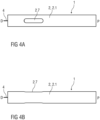
- the needle shroud 7 moves from the retracted position RP towards a second extended position SEP driven by the shroud spring 8 to cover the needle 4.
- the needle shroud 7 protrudes further from the case 2 than in the extended position EP and is locked in an axial position relative to the case 2.
- the shroud beam 7.1 is deflected radially outwards around the case backstop beam 2.4. Once the shroud beam 7.1 has passed the case backstop beam 2.4, it returns to a non-deflected position radially inward.
- the needle shroud 7 cannot be translated in the proximal direction P relative to the case 2 from the second extended position SEP, because the shroud beam 7.1 will abut the case backstop beam 2.4, which is inwardly supported by the syringe 3 and can hence not deflect in the radially inward direction to allow the shroud beam 7.1 to pass.
- the needle shroud 7 is thus locked in the second extended position SEP. Further extension of the needle shroud 7 is prevented by a case boss 2.8 engaging with an end of a slot 7.3 in the needle shroud 7.
- the needle shroud 7 will translate to the second extended position SEP. Hence, the risk of post-injection needle stick injury is reduced.
- drug or “medicament”, as used herein, means a pharmaceutical formulation containing at least one pharmaceutically active compound
- Insulin analogues are for example Gly(A21), Arg(B31), Arg(B32) human insulin; Lys(B3), Glu(B29) human insulin; Lys(B28), Pro(B29) human insulin; Asp(B28) human insulin; human insulin, wherein proline in position B28 is replaced by Asp, Lys, Leu, Val or Ala and wherein in position B29 Lys may be replaced by Pro; Ala(B26) human insulin; Des(B28-B30) human insulin; Des(B27) human insulin and Des(B30) human insulin.
- Insulin derivates are for example B29-N-myristoyl-des(B30) human insulin; B29-N-palmitoyl-des(B30) human insulin; B29-N-myristoyl human insulin; B29-N-palmitoyl human insulin; B28-N-myristoyl LysB28ProB29 human insulin; B28-N-palmitoyl-LysB28ProB29 human insulin; B30-N-myristoyl-ThrB29LysB30 human insulin; B30-N-palmitoyl- ThrB29LysB30 human insulin; B29-N-(N-palmitoyl-Y-glutamyl)-des(B30) human insulin; B29-N-(N-lithocholyl-Y-glutamyl)-des(B30) human insulin; B29-N-( ⁇ -carboxyheptadecanoyl)-des(B30) human insulin and B29-N-( ⁇ -carbox
- Exendin-4 for example means Exendin-4(1-39), a peptide of the sequence H-His-Gly-Glu-Gly-Thr-Phe-Thr-Ser-Asp-Leu-Ser-Lys-Gln-Met-Glu-Glu-Glu-Ala-Val-Arg-Leu-Phe-Ile-Glu-Trp-Leu-Lys-Asn-Gly-Gly-Pro-Ser-Ser-Gly-Ala-Pro-Pro-Pro-Ser-NH2.
- Exendin-4 derivatives are for example selected from the following list of compounds:
- Hormones are for example hypophysis hormones or hypothalamus hormones or regulatory active peptides and their antagonists as listed in Rote Liste, ed. 2008, Chapter 50 , such as Gonadotropine (Follitropin, Lutropin, Choriongonadotropin, Menotropin), Somatropine (Somatropin), Desmopressin, Terlipressin, Gonadorelin, Triptorelin, Leuprorelin, Buserelin, Nafarelin, Goserelin.
- Gonadotropine Follitropin, Lutropin, Choriongonadotropin, Menotropin
- Somatropine Somatropin
- Desmopressin Terlipressin
- Gonadorelin Triptorelin
- Leuprorelin Buserelin
- Nafarelin Goserelin.
- a polysaccharide is for example a glucosaminoglycane, a hyaluronic acid, a heparin, a low molecular weight heparin or an ultra low molecular weight heparin or a derivative thereof, or a sulphated, e.g. a poly-sulphated form of the above-mentioned polysaccharides, and/or a pharmaceutically acceptable salt thereof.
- An example of a pharmaceutically acceptable salt of a poly-sulphated low molecular weight heparin is enoxaparin sodium.
- Antibodies are globular plasma proteins ( ⁇ 150 kDa) that are also known as immunoglobulins which share a basic structure. As they have sugar chains added to amino acid residues, they are glycoproteins.
- the basic functional unit of each antibody is an immunoglobulin (Ig) monomer (containing only one Ig unit); secreted antibodies can also be dimeric with two Ig units as with IgA, tetrameric with four Ig units like teleost fish IgM, or pentameric with five Ig units, like mammalian IgM.
- Ig immunoglobulin
- the Ig monomer is a "Y"-shaped molecule that consists of four polypeptide chains; two identical heavy chains and two identical light chains connected by disulfide bonds between cysteine residues. Each heavy chain is about 440 amino acids long; each light chain is about 220 amino acids long. Heavy and light chains each contain intrachain disulfide bonds which stabilize their folding. Each chain is composed of structural domains called Ig domains. These domains contain about 70-110 amino acids and are classified into different categories (for example, variable or V, and constant or C) according to their size and function. They have a characteristic immunoglobulin fold in which two ⁇ sheets create a "sandwich" shape, held together by interactions between conserved cysteines and other charged amino acids.
- Ig heavy chain There are five types of mammalian Ig heavy chain denoted by ⁇ , ⁇ , ⁇ , ⁇ , and ⁇ .
- the type of heavy chain present defines the isotype of antibody; these chains are found in IgA, IgD, IgE, IgG, and IgM antibodies, respectively.
- Distinct heavy chains differ in size and composition; ⁇ and ⁇ contain approximately 450 amino acids and ⁇ approximately 500 amino acids, while ⁇ and ⁇ have approximately 550 amino acids.
- Each heavy chain has two regions, the constant region (C H ) and the variable region (V H ).
- the constant region is essentially identical in all antibodies of the same isotype, but differs in antibodies of different isotypes.
- Heavy chains ⁇ , ⁇ and ⁇ have a constant region composed of three tandem Ig domains, and a hinge region for added flexibility; heavy chains ⁇ and ⁇ have a constant region composed of four immunoglobulin domains.
- the variable region of the heavy chain differs in antibodies produced by different B cells, but is the same for all antibodies produced by a single B cell or B cell clone.
- the variable region of each heavy chain is approximately 110 amino acids long and is composed of a single Ig domain.
- a light chain has two successive domains: one constant domain (CL) and one variable domain (VL).
- CL constant domain
- VL variable domain
- the approximate length of a light chain is 211 to 217 amino acids.
- Each antibody contains two light chains that are always identical; only one type of light chain, ⁇ or ⁇ , is present per antibody in mammals.
- variable (V) regions are responsible for binding to the antigen, i.e. for its antigen specificity.
- VL variable light
- VH variable heavy chain
- CDRs Complementarity Determining Regions
- an "antibody fragment” contains at least one antigen binding fragment as defined above, and exhibits essentially the same function and specificity as the complete antibody of which the fragment is derived from.
- Limited proteolytic digestion with papain cleaves the Ig prototype into three fragments. Two identical amino terminal fragments, each containing one entire L chain and about half an H chain, are the antigen binding fragments (Fab).
- the Fc contains carbohydrates, complement-binding, and FcR-binding sites.
- F(ab')2 is divalent for antigen binding.
- the disulfide bond of F(ab')2 may be cleaved in order to obtain Fab'.
- the variable regions of the heavy and light chains can be fused together to form a single chain variable fragment (scFv).
- Pharmaceutically acceptable salts are for example acid addition salts and basic salts.
- Acid addition salts are e.g. HCl or HBr salts.
- Basic salts are e.g. salts having a cation selected from alkali or alkaline, e.g. Na+, or K+, or Ca2+, or an ammonium ion N+(R1)(R2)(R3)(R4), wherein R1 to R4 independently of each other mean: hydrogen, an optionally substituted C1-C6-alkyl group, an optionally substituted C2-C6-alkenyl group, an optionally substituted C6-C10-aryl group, or an optionally substituted C6-C10-heteroaryl group.
- solvates are for example hydrates.
Landscapes
- Health & Medical Sciences (AREA)
- Engineering & Computer Science (AREA)
- Hematology (AREA)
- Anesthesiology (AREA)
- Biomedical Technology (AREA)
- Heart & Thoracic Surgery (AREA)
- Vascular Medicine (AREA)
- Life Sciences & Earth Sciences (AREA)
- Animal Behavior & Ethology (AREA)
- General Health & Medical Sciences (AREA)
- Public Health (AREA)
- Veterinary Medicine (AREA)
- Infusion, Injection, And Reservoir Apparatuses (AREA)
- Environmental & Geological Engineering (AREA)
Claims (13)
- Autoinjektor (1), aufweisend:ein Gehäuse (2), das dazu ausgeführt ist, einen Medikamentbehälter (3) mit einer Nadel (4) zu halten, wobei das Gehäuse (2) eine abgewinkelte Rippe (2.6) aufweist,eine Nadelabdeckung (7), die verschiebbar in dem Gehäuse (2) angeordnet und zwischen einer relativ zu dem Gehäuse (2) ausgezogenen Position (EP), in der die Nadel (4) abgedeckt ist, und einer relativ zu dem Gehäuse (2) zurückgezogenen Position (RP), in der die Nadel (4) freiliegt, verschiebbar ist,einen Kolben (10), der verschiebbar in dem Gehäuse (2) angeordnet ist, wobei der Kolben (10) einen Kolbenansatz (10.1) aufweist, undeine Antriebsfeder (9), die zum Vorspannen des Kolbens (10) relativ zu dem Gehäuse (2) ausgestaltet ist,wobei der Kolbenansatz (10.1) dazu ausgeführt ist, an der Rippe (2.6) und der Nadelabdeckung (7) anzuliegen, wenn die Nadelabdeckung in der ausgezogenen Position (EP) ist, und aus der Rippe auszurücken, wenn die Nadelabdeckung in der zurückgezogenen Position (RP) ist, damit sich der Kolben axial relativ zu dem Gehäuse (2) verschieben kann, unddadurch gekennzeichnet, dass der Kolben (10) hohl ist und die Antriebsfeder (9) in dem Kolben (10) angeordnet ist.
- Autoinjektor (1) nach Anspruch 1, wobei der Kolbenansatz (10.1) dazu ausgeführt ist, an der Rippe (2.6) anzuliegen, wenn der Kolben (10) gegen die Rippe (2.6) vorgespannt wird, um den Kolbenansatz (10.1) zu drehen.
- Autoinjektor (1) nach einem der vorhergehenden Ansprüche, ferner aufweisend:
eine Abdeckungsfeder (8), die die Nadelabdeckung (7) zu der ausgezogenen Position (EP) hin vorspannt. - Autoinjektor (1) nach einem der vorhergehenden Ansprüche, wobei das Gehäuse (2) ein Sichtfenster (2.7) aufweist.
- Autoinjektor (1) nach Anspruch 4, wobei das Sichtfenster (2.7) so ausgestaltet ist, dass das Vorschieben des Kolbens (10) durch das Sichtfenster beobachtet werden kann.
- Autoinjektor (1) nach einem der vorhergehenden Ansprüche, ferner aufweisend:
eine Kappe (11), die an eine Nadelschutzhülle (5) gekoppelt ist, die die Nadel (4) abdeckt. - Autoinjektor (1) nach Anspruch 6, wobei die Kappe (11) dazu ausgestaltet ist, an der Nadelschutzhülle (5) mittels eines Widerhakens, einer Einschnappverbindung, Reibung und/oder Haken einzugreifen.
- Autoinjektor (1) nach Anspruch 6 oder 7, wobei die Kappe (11) dazu ausgestaltet ist, an der Nadelabdeckung (7) und/oder dem Gehäuses (2) einzugreifen.
- Autoinjektor (1) nach einem der vorhergehenden Ansprüche, wobei die Nadelabdeckung (7) einen ersten Abdeckungsansatz (7.2) aufweist, der dazu ausgestaltet ist, an dem Kolbenansatz (10.2) anzuliegen, wenn die Nadelabdeckung in der ausgezogenen Position (EP) ist.
- Autoinjektor (1) nach Anspruch 9, wobei der erste Abdeckungsansatz (7.2) ein Widerstandselement (7.5) aufweist, das dazu ausgestaltet ist, ein haptisches Feedback erhöhten Widerstands gegen eine Translation der Nadelabdeckung (7) in eine proximale Richtung (P) zu erzeugen, wenn es an dem Kolbenansatz (10.1) anliegt.
- Autoinjektor (1) nach einem der vorhergehenden Ansprüche, wobei das Gehäuse (2) einen Gehäuseansatz (2.8) aufweist, der dazu ausgestaltet ist, an einem Ende eines Schlitzes (7.3) in der Nadelabdeckung (7) einzugreifen.
- Autoinjektor (1) nach einem der vorhergehenden Ansprüche, wobei die Rippe (2.6) bezüglich einer Längsachse des Gehäuses (2) abgewinkelt ist und eine Rotations- und eine Axialkraft auf den Kolbenansatz (10.1) ausübt.
- Autoinjektor (1) nach einem der vorhergehenden Ansprüche, wobei der Medikamentbehälter (3) eine Spritze ist, die ein Medikament enthält.
Priority Applications (1)
| Application Number | Priority Date | Filing Date | Title |
|---|---|---|---|
| EP24183755.8A EP4445932A3 (de) | 2013-07-09 | 2014-07-07 | Autoinjektor |
Applications Claiming Priority (4)
| Application Number | Priority Date | Filing Date | Title |
|---|---|---|---|
| EP13175661.1A EP2823838A1 (de) | 2013-07-09 | 2013-07-09 | Autoinjektor |
| PCT/EP2014/064424 WO2015004049A1 (en) | 2013-07-09 | 2014-07-07 | Autoinjector |
| EP14735594.5A EP3019216B1 (de) | 2013-07-09 | 2014-07-07 | Autoinjektor |
| EP18187979.2A EP3434301B1 (de) | 2013-07-09 | 2014-07-07 | Autoinjektor |
Related Parent Applications (2)
| Application Number | Title | Priority Date | Filing Date |
|---|---|---|---|
| EP14735594.5A Division EP3019216B1 (de) | 2013-07-09 | 2014-07-07 | Autoinjektor |
| EP18187979.2A Division EP3434301B1 (de) | 2013-07-09 | 2014-07-07 | Autoinjektor |
Related Child Applications (2)
| Application Number | Title | Priority Date | Filing Date |
|---|---|---|---|
| EP24183755.8A Division EP4445932A3 (de) | 2013-07-09 | 2014-07-07 | Autoinjektor |
| EP24183755.8A Division-Into EP4445932A3 (de) | 2013-07-09 | 2014-07-07 | Autoinjektor |
Publications (2)
| Publication Number | Publication Date |
|---|---|
| EP4046672A1 EP4046672A1 (de) | 2022-08-24 |
| EP4046672B1 true EP4046672B1 (de) | 2024-07-31 |
Family
ID=48747443
Family Applications (5)
| Application Number | Title | Priority Date | Filing Date |
|---|---|---|---|
| EP13175661.1A Withdrawn EP2823838A1 (de) | 2013-07-09 | 2013-07-09 | Autoinjektor |
| EP22167357.7A Active EP4046672B1 (de) | 2013-07-09 | 2014-07-07 | Autoinjektor |
| EP14735594.5A Active EP3019216B1 (de) | 2013-07-09 | 2014-07-07 | Autoinjektor |
| EP24183755.8A Pending EP4445932A3 (de) | 2013-07-09 | 2014-07-07 | Autoinjektor |
| EP18187979.2A Active EP3434301B1 (de) | 2013-07-09 | 2014-07-07 | Autoinjektor |
Family Applications Before (1)
| Application Number | Title | Priority Date | Filing Date |
|---|---|---|---|
| EP13175661.1A Withdrawn EP2823838A1 (de) | 2013-07-09 | 2013-07-09 | Autoinjektor |
Family Applications After (3)
| Application Number | Title | Priority Date | Filing Date |
|---|---|---|---|
| EP14735594.5A Active EP3019216B1 (de) | 2013-07-09 | 2014-07-07 | Autoinjektor |
| EP24183755.8A Pending EP4445932A3 (de) | 2013-07-09 | 2014-07-07 | Autoinjektor |
| EP18187979.2A Active EP3434301B1 (de) | 2013-07-09 | 2014-07-07 | Autoinjektor |
Country Status (13)
| Country | Link |
|---|---|
| US (4) | US10525206B2 (de) |
| EP (5) | EP2823838A1 (de) |
| JP (1) | JP6408571B2 (de) |
| KR (1) | KR20160029100A (de) |
| CN (1) | CN105517598B (de) |
| AR (1) | AR096829A1 (de) |
| AU (1) | AU2014289349B2 (de) |
| DK (3) | DK3019216T3 (de) |
| IL (1) | IL243224A0 (de) |
| MX (1) | MX2016000312A (de) |
| RU (1) | RU2675683C2 (de) |
| TW (1) | TW201513908A (de) |
| WO (1) | WO2015004049A1 (de) |
Families Citing this family (43)
| Publication number | Priority date | Publication date | Assignee | Title |
|---|---|---|---|---|
| EP2823841A1 (de) | 2013-07-09 | 2015-01-14 | Sanofi-Aventis Deutschland GmbH | Autoinjektor |
| EP2823838A1 (de) * | 2013-07-09 | 2015-01-14 | Sanofi-Aventis Deutschland GmbH | Autoinjektor |
| EP2923714A1 (de) | 2014-03-28 | 2015-09-30 | Sanofi-Aventis Deutschland GmbH | Durch hautkontakt ausgelöste Autoinjektor |
| TW201711716A (zh) * | 2015-06-03 | 2017-04-01 | 賽諾菲阿凡提斯德意志有限公司 | 護罩鎖 |
| TW201709941A (zh) | 2015-06-03 | 2017-03-16 | 賽諾菲阿凡提斯德意志有限公司 | 聲響指示器(二) |
| TW201707737A (zh) | 2015-06-03 | 2017-03-01 | 賽諾菲阿凡提斯德意志有限公司 | 藥物輸送裝置(一) |
| TW201707741A (zh) | 2015-06-03 | 2017-03-01 | 賽諾菲阿凡提斯德意志有限公司 | 針頭護罩之抓握器、蓋子、自動注射器及製造抓握器之方法 |
| TW201709940A (zh) | 2015-06-03 | 2017-03-16 | 賽諾菲阿凡提斯德意志有限公司 | 聲響指示器(一) |
| TW201700118A (zh) | 2015-06-03 | 2017-01-01 | 賽諾菲阿凡提斯德意志有限公司 | 藥物輸送裝置(三) |
| USD866757S1 (en) * | 2016-03-11 | 2019-11-12 | Millennium Pharmaceuticals, Inc. | Autoinjector |
| US11654246B2 (en) | 2017-11-03 | 2023-05-23 | Sanofi | Drug delivery device |
| EP3492123A1 (de) | 2017-12-01 | 2019-06-05 | Sanofi | Injektorvorrichtung |
| WO2019144048A1 (en) | 2018-01-19 | 2019-07-25 | Birya Biotech, Inc. | Tool for servicing an auto-injector |
| AU2019273833B2 (en) * | 2018-05-24 | 2022-03-24 | Novartis Ag | Automatic drug delivery device |
| LT3801694T (lt) | 2018-06-08 | 2025-12-10 | Antares Pharma, Inc. | Automatinio įterpimo injektorius |
| WO2020173995A1 (en) * | 2019-02-26 | 2020-09-03 | Becton Dickinson France | Auto-injector with cap |
| JP7356507B2 (ja) * | 2019-02-26 | 2023-10-04 | ベクトン ディキンソン フランス | ロッククリップ付き自動注射器 |
| JP7385670B2 (ja) | 2019-02-26 | 2023-11-22 | ベクトン ディキンソン フランス | 自動注射器用のドロップテスト機能付き硬質針シールド除去器 |
| WO2020173993A1 (en) | 2019-02-26 | 2020-09-03 | Becton Dickinson France | Auto-injector with audio indicator |
| US20210093797A1 (en) * | 2019-09-30 | 2021-04-01 | Amgen Inc. | Drug delivery device |
| IL291004B1 (en) | 2019-09-30 | 2026-04-01 | Amgen Inc | Drug delivery device |
| CA3152549A1 (en) | 2019-09-30 | 2021-04-08 | Amgen Inc. | Drug delivery device |
| AU2020357511B2 (en) * | 2019-09-30 | 2026-02-12 | Amgen Inc. | Drug delivery device |
| WO2021067210A1 (en) * | 2019-09-30 | 2021-04-08 | Amgen Inc. | Drug delivery device and methods of delivering a drug |
| BR112022005996A2 (pt) * | 2019-09-30 | 2022-07-12 | Amgen Inc | Dispositivo de administração de fármaco |
| US20220339363A1 (en) * | 2019-10-23 | 2022-10-27 | Becton Dickinson France | Injection Device Comprising a Needle Shield |
| CN114599413B (zh) * | 2019-10-23 | 2024-11-08 | 贝克顿迪金森法国公司 | 注射装置 |
| CN117651577A (zh) * | 2021-06-02 | 2024-03-05 | 赛诺菲 | 药物递送装置、柱塞杆、柱塞杆组、用于组装药物递送装置的方法及药物递送装置组 |
| WO2023057773A1 (en) | 2021-10-08 | 2023-04-13 | Actuate Technology Ltd | Drug delivery device |
| CN118632721A (zh) * | 2021-12-15 | 2024-09-10 | 赛诺菲 | 包括捏皮机构的药物递送布置 |
| WO2024094705A1 (en) | 2022-10-31 | 2024-05-10 | Sanofi | Drug delivery device having a two-part user indicator |
| EP4611846A1 (de) | 2022-10-31 | 2025-09-10 | Sanofi | Kolben zum ausstossen eines arzneimittels, arzneimittelabgabevorrichtung, hintere unteranordnung und zugehörige verfahren |
| WO2024094700A1 (en) | 2022-10-31 | 2024-05-10 | Sanofi | Method for assembling an assembly for a drug delivery device and drug delivery device. |
| CN120476001A (zh) | 2022-10-31 | 2025-08-12 | 赛诺菲 | 用于药物递送装置的前子组件 |
| CN120129547A (zh) * | 2022-10-31 | 2025-06-10 | 赛诺菲 | 用于药物递送装置的装置本体、用于药物递送装置的组件以及药物递送装置 |
| EP4611847A1 (de) | 2022-10-31 | 2025-09-10 | Sanofi | Behälterhalter und arzneimittelabgabevorrichtung mit dem behälterhalter |
| WO2024094706A1 (en) | 2022-10-31 | 2024-05-10 | Sanofi | Audible indicator, indicator holder and method of assembling an audible indicator |
| WO2024094704A1 (en) | 2022-10-31 | 2024-05-10 | Sanofi | Arrangement for a drug delivery device, drug delivery device and method for assembly |
| EP4611853A1 (de) | 2022-10-31 | 2025-09-10 | Sanofi | Anordnung für eine arzneimittelabgabevorrichtung |
| EP4611851A1 (de) | 2022-10-31 | 2025-09-10 | Sanofi | Arzneimittelabgabevorrichtung mit rückkopplungselement und verfahren zur rückmeldung einer arzneimittelabgabevorrichtung an einen benutzer bezüglich eines dosisabgabeverfahrens |
| WO2025162927A1 (en) | 2024-01-29 | 2025-08-07 | Sanofi | Purifying device, system and method for purifying a needle for delivering a medicament |
| WO2025162928A1 (en) | 2024-01-29 | 2025-08-07 | Sanofi | Needle shroud unlock device for a medicament delivery device |
| WO2025162926A1 (en) | 2024-01-29 | 2025-08-07 | Sanofi | Needle arrangement, drug delivery device comprising the needle arrangement and method for operating the drug delivery device |
Family Cites Families (23)
| Publication number | Priority date | Publication date | Assignee | Title |
|---|---|---|---|---|
| US2399633A (en) * | 1942-08-15 | 1946-05-07 | Ralph A Harding | Peep sight |
| US5762646A (en) * | 1996-09-30 | 1998-06-09 | Duxbury Scientific, Inc. | Blood collection system and coupling |
| CN101119761B (zh) | 2004-11-24 | 2010-08-18 | Shl医药公司 | 注射设备 |
| FR2908753B1 (fr) | 2006-11-16 | 2011-11-11 | Becton Dickinson France | Dispositif pour delivrer automatiquement des doses successives de produit |
| US8308695B2 (en) | 2007-11-14 | 2012-11-13 | Shl Group Ab | Automatic injection device with actively triggered syringe withdrawal |
| US8858501B2 (en) | 2008-04-11 | 2014-10-14 | Medtronic Minimed, Inc. | Reservoir barrier layer systems and methods |
| DE102008037310B4 (de) * | 2008-08-11 | 2023-11-16 | Ypsomed Ag | Automatische Injektionsvorrichtung für die Verabreichung einer festen Dosis |
| GB0900930D0 (en) | 2009-01-20 | 2009-03-04 | Future Injection Technologies Ltd | Injection device |
| KR101721906B1 (ko) * | 2009-04-29 | 2017-03-31 | 애브비 바이오테크놀로지 리미티드 | 자동 주입 장치 |
| JP5886750B2 (ja) | 2009-10-16 | 2016-03-16 | ヤンセン バイオテツク,インコーポレーテツド | 手のひら作動式薬物送達装置 |
| WO2011101383A1 (en) * | 2010-02-22 | 2011-08-25 | Sanofi-Aventis Deutschland Gmbh | Force transmission arrangement for auto-injector |
| CN103120819B (zh) | 2010-03-31 | 2015-05-06 | Shl集团有限责任公司 | 药物输送设备 |
| EP2399627A1 (de) * | 2010-06-28 | 2011-12-28 | Sanofi-Aventis Deutschland GmbH | Automatischer Injektor |
| EP2399633A1 (de) * | 2010-06-28 | 2011-12-28 | Sanofi-Aventis Deutschland GmbH | Nadel-Sicherheitsanordnung und Betriebsverfahren |
| TWI471151B (zh) | 2011-01-11 | 2015-02-01 | Shl Group Ab | 藥物輸送裝置 |
| WO2012122643A1 (en) * | 2011-03-11 | 2012-09-20 | University Of Saskatchewan | Injection assist device and method |
| US8496619B2 (en) | 2011-07-15 | 2013-07-30 | Antares Pharma, Inc. | Injection device with cammed ram assembly |
| ITFI20110194A1 (it) * | 2011-09-08 | 2013-03-09 | Menarini Int Operations Lu Sa | Dispositivo autoiniettore di dosi di farmaco |
| KR101664632B1 (ko) | 2011-09-27 | 2016-10-24 | 에스에이치엘 그룹 에이비 | 최초 로크된 상태, 중간 프라이밍 상태, 및 약물 주입 상태를 갖는 약물 주입 장치 |
| EP2782624B1 (de) | 2011-11-25 | 2020-04-29 | SHL Medical AG | Vorrichtung zur medikamentenverabreichung |
| EP2606924A1 (de) * | 2011-12-21 | 2013-06-26 | Sanofi-Aventis Deutschland GmbH | Autoinjektor |
| US9364610B2 (en) | 2012-05-07 | 2016-06-14 | Antares Pharma, Inc. | Injection device with cammed ram assembly |
| EP2823838A1 (de) * | 2013-07-09 | 2015-01-14 | Sanofi-Aventis Deutschland GmbH | Autoinjektor |
-
2013
- 2013-07-09 EP EP13175661.1A patent/EP2823838A1/de not_active Withdrawn
-
2014
- 2014-07-07 EP EP22167357.7A patent/EP4046672B1/de active Active
- 2014-07-07 MX MX2016000312A patent/MX2016000312A/es unknown
- 2014-07-07 DK DK14735594.5T patent/DK3019216T3/en active
- 2014-07-07 EP EP14735594.5A patent/EP3019216B1/de active Active
- 2014-07-07 JP JP2016524773A patent/JP6408571B2/ja active Active
- 2014-07-07 DK DK22167357.7T patent/DK4046672T3/da active
- 2014-07-07 DK DK18187979.2T patent/DK3434301T3/da active
- 2014-07-07 AR ARP140102513A patent/AR096829A1/es unknown
- 2014-07-07 WO PCT/EP2014/064424 patent/WO2015004049A1/en not_active Ceased
- 2014-07-07 RU RU2016103905A patent/RU2675683C2/ru not_active IP Right Cessation
- 2014-07-07 KR KR1020167002896A patent/KR20160029100A/ko not_active Withdrawn
- 2014-07-07 EP EP24183755.8A patent/EP4445932A3/de active Pending
- 2014-07-07 EP EP18187979.2A patent/EP3434301B1/de active Active
- 2014-07-07 CN CN201480048984.9A patent/CN105517598B/zh active Active
- 2014-07-07 TW TW103123251A patent/TW201513908A/zh unknown
- 2014-07-07 US US14/903,398 patent/US10525206B2/en active Active
- 2014-07-07 AU AU2014289349A patent/AU2014289349B2/en not_active Expired - Fee Related
-
2015
- 2015-12-24 IL IL243224A patent/IL243224A0/en unknown
-
2019
- 2019-12-19 US US16/721,467 patent/US11260181B2/en active Active
-
2022
- 2022-01-27 US US17/586,272 patent/US12076540B2/en active Active
-
2024
- 2024-07-30 US US18/789,584 patent/US20240382691A1/en active Pending
Also Published As
Similar Documents
| Publication | Publication Date | Title |
|---|---|---|
| US12076540B2 (en) | Autoinjector | |
| US12070589B2 (en) | Autoinjector | |
| US10758682B2 (en) | Autoinjector | |
| EP4056212B1 (de) | Autoinjektor | |
| EP2823836A1 (de) | Autoinjektor | |
| HK40079870A (en) | Autoinjector | |
| HK40081254A (en) | Autoinjector | |
| HK1218521B (en) | Autoinjector | |
| HK1218400B (en) | Autoinjector |
Legal Events
| Date | Code | Title | Description |
|---|---|---|---|
| PUAI | Public reference made under article 153(3) epc to a published international application that has entered the european phase |
Free format text: ORIGINAL CODE: 0009012 |
|
| STAA | Information on the status of an ep patent application or granted ep patent |
Free format text: STATUS: THE APPLICATION HAS BEEN PUBLISHED |
|
| AC | Divisional application: reference to earlier application |
Ref document number: 3019216 Country of ref document: EP Kind code of ref document: P Ref document number: 3434301 Country of ref document: EP Kind code of ref document: P |
|
| AK | Designated contracting states |
Kind code of ref document: A1 Designated state(s): AL AT BE BG CH CY CZ DE DK EE ES FI FR GB GR HR HU IE IS IT LI LT LU LV MC MK MT NL NO PL PT RO RS SE SI SK SM TR |
|
| STAA | Information on the status of an ep patent application or granted ep patent |
Free format text: STATUS: REQUEST FOR EXAMINATION WAS MADE |
|
| 17P | Request for examination filed |
Effective date: 20230223 |
|
| RBV | Designated contracting states (corrected) |
Designated state(s): AL AT BE BG CH CY CZ DE DK EE ES FI FR GB GR HR HU IE IS IT LI LT LU LV MC MK MT NL NO PL PT RO RS SE SI SK SM TR |
|
| REG | Reference to a national code |
Ref country code: HK Ref legal event code: DE Ref document number: 40079870 Country of ref document: HK |
|
| GRAP | Despatch of communication of intention to grant a patent |
Free format text: ORIGINAL CODE: EPIDOSNIGR1 |
|
| STAA | Information on the status of an ep patent application or granted ep patent |
Free format text: STATUS: GRANT OF PATENT IS INTENDED |
|
| RIC1 | Information provided on ipc code assigned before grant |
Ipc: A61M 5/32 20060101ALN20240131BHEP Ipc: A61M 5/50 20060101ALI20240131BHEP Ipc: A61M 5/20 20060101AFI20240131BHEP |
|
| INTG | Intention to grant announced |
Effective date: 20240221 |
|
| GRAS | Grant fee paid |
Free format text: ORIGINAL CODE: EPIDOSNIGR3 |
|
| GRAA | (expected) grant |
Free format text: ORIGINAL CODE: 0009210 |
|
| STAA | Information on the status of an ep patent application or granted ep patent |
Free format text: STATUS: THE PATENT HAS BEEN GRANTED |
|
| P01 | Opt-out of the competence of the unified patent court (upc) registered |
Free format text: CASE NUMBER: APP_35259/2024 Effective date: 20240612 |
|
| AC | Divisional application: reference to earlier application |
Ref document number: 3019216 Country of ref document: EP Kind code of ref document: P Ref document number: 3434301 Country of ref document: EP Kind code of ref document: P |
|
| AK | Designated contracting states |
Kind code of ref document: B1 Designated state(s): AL AT BE BG CH CY CZ DE DK EE ES FI FR GB GR HR HU IE IS IT LI LT LU LV MC MK MT NL NO PL PT RO RS SE SI SK SM TR |
|
| REG | Reference to a national code |
Ref country code: CH Ref legal event code: EP Ref country code: GB Ref legal event code: FG4D |
|
| REG | Reference to a national code |
Ref country code: DE Ref legal event code: R096 Ref document number: 602014090638 Country of ref document: DE |
|
| REG | Reference to a national code |
Ref country code: IE Ref legal event code: FG4D |
|
| REG | Reference to a national code |
Ref country code: DK Ref legal event code: T3 Effective date: 20241018 |
|
| REG | Reference to a national code |
Ref country code: LT Ref legal event code: MG9D |
|
| REG | Reference to a national code |
Ref country code: NL Ref legal event code: MP Effective date: 20240731 |
|
| PG25 | Lapsed in a contracting state [announced via postgrant information from national office to epo] |
Ref country code: PT Free format text: LAPSE BECAUSE OF FAILURE TO SUBMIT A TRANSLATION OF THE DESCRIPTION OR TO PAY THE FEE WITHIN THE PRESCRIBED TIME-LIMIT Effective date: 20241202 |
|
| REG | Reference to a national code |
Ref country code: AT Ref legal event code: MK05 Ref document number: 1707888 Country of ref document: AT Kind code of ref document: T Effective date: 20240731 |
|
| PG25 | Lapsed in a contracting state [announced via postgrant information from national office to epo] |
Ref country code: PT Free format text: LAPSE BECAUSE OF FAILURE TO SUBMIT A TRANSLATION OF THE DESCRIPTION OR TO PAY THE FEE WITHIN THE PRESCRIBED TIME-LIMIT Effective date: 20241202 |
|
| PG25 | Lapsed in a contracting state [announced via postgrant information from national office to epo] |
Ref country code: NO Free format text: LAPSE BECAUSE OF FAILURE TO SUBMIT A TRANSLATION OF THE DESCRIPTION OR TO PAY THE FEE WITHIN THE PRESCRIBED TIME-LIMIT Effective date: 20241031 |
|
| PG25 | Lapsed in a contracting state [announced via postgrant information from national office to epo] |
Ref country code: NL Free format text: LAPSE BECAUSE OF FAILURE TO SUBMIT A TRANSLATION OF THE DESCRIPTION OR TO PAY THE FEE WITHIN THE PRESCRIBED TIME-LIMIT Effective date: 20240731 Ref country code: FI Free format text: LAPSE BECAUSE OF FAILURE TO SUBMIT A TRANSLATION OF THE DESCRIPTION OR TO PAY THE FEE WITHIN THE PRESCRIBED TIME-LIMIT Effective date: 20240731 Ref country code: PL Free format text: LAPSE BECAUSE OF FAILURE TO SUBMIT A TRANSLATION OF THE DESCRIPTION OR TO PAY THE FEE WITHIN THE PRESCRIBED TIME-LIMIT Effective date: 20240731 Ref country code: GR Free format text: LAPSE BECAUSE OF FAILURE TO SUBMIT A TRANSLATION OF THE DESCRIPTION OR TO PAY THE FEE WITHIN THE PRESCRIBED TIME-LIMIT Effective date: 20241101 |
|
| PG25 | Lapsed in a contracting state [announced via postgrant information from national office to epo] |
Ref country code: BG Free format text: LAPSE BECAUSE OF FAILURE TO SUBMIT A TRANSLATION OF THE DESCRIPTION OR TO PAY THE FEE WITHIN THE PRESCRIBED TIME-LIMIT Effective date: 20240731 |
|
| PG25 | Lapsed in a contracting state [announced via postgrant information from national office to epo] |
Ref country code: LV Free format text: LAPSE BECAUSE OF FAILURE TO SUBMIT A TRANSLATION OF THE DESCRIPTION OR TO PAY THE FEE WITHIN THE PRESCRIBED TIME-LIMIT Effective date: 20240731 |
|
| PG25 | Lapsed in a contracting state [announced via postgrant information from national office to epo] |
Ref country code: AT Free format text: LAPSE BECAUSE OF FAILURE TO SUBMIT A TRANSLATION OF THE DESCRIPTION OR TO PAY THE FEE WITHIN THE PRESCRIBED TIME-LIMIT Effective date: 20240731 Ref country code: IS Free format text: LAPSE BECAUSE OF FAILURE TO SUBMIT A TRANSLATION OF THE DESCRIPTION OR TO PAY THE FEE WITHIN THE PRESCRIBED TIME-LIMIT Effective date: 20241130 |
|
| PG25 | Lapsed in a contracting state [announced via postgrant information from national office to epo] |
Ref country code: HR Free format text: LAPSE BECAUSE OF FAILURE TO SUBMIT A TRANSLATION OF THE DESCRIPTION OR TO PAY THE FEE WITHIN THE PRESCRIBED TIME-LIMIT Effective date: 20240731 |
|
| PG25 | Lapsed in a contracting state [announced via postgrant information from national office to epo] |
Ref country code: ES Free format text: LAPSE BECAUSE OF FAILURE TO SUBMIT A TRANSLATION OF THE DESCRIPTION OR TO PAY THE FEE WITHIN THE PRESCRIBED TIME-LIMIT Effective date: 20240731 Ref country code: RS Free format text: LAPSE BECAUSE OF FAILURE TO SUBMIT A TRANSLATION OF THE DESCRIPTION OR TO PAY THE FEE WITHIN THE PRESCRIBED TIME-LIMIT Effective date: 20241031 |
|
| PG25 | Lapsed in a contracting state [announced via postgrant information from national office to epo] |
Ref country code: RS Free format text: LAPSE BECAUSE OF FAILURE TO SUBMIT A TRANSLATION OF THE DESCRIPTION OR TO PAY THE FEE WITHIN THE PRESCRIBED TIME-LIMIT Effective date: 20241031 Ref country code: PL Free format text: LAPSE BECAUSE OF FAILURE TO SUBMIT A TRANSLATION OF THE DESCRIPTION OR TO PAY THE FEE WITHIN THE PRESCRIBED TIME-LIMIT Effective date: 20240731 Ref country code: NO Free format text: LAPSE BECAUSE OF FAILURE TO SUBMIT A TRANSLATION OF THE DESCRIPTION OR TO PAY THE FEE WITHIN THE PRESCRIBED TIME-LIMIT Effective date: 20241031 Ref country code: NL Free format text: LAPSE BECAUSE OF FAILURE TO SUBMIT A TRANSLATION OF THE DESCRIPTION OR TO PAY THE FEE WITHIN THE PRESCRIBED TIME-LIMIT Effective date: 20240731 Ref country code: LV Free format text: LAPSE BECAUSE OF FAILURE TO SUBMIT A TRANSLATION OF THE DESCRIPTION OR TO PAY THE FEE WITHIN THE PRESCRIBED TIME-LIMIT Effective date: 20240731 Ref country code: IS Free format text: LAPSE BECAUSE OF FAILURE TO SUBMIT A TRANSLATION OF THE DESCRIPTION OR TO PAY THE FEE WITHIN THE PRESCRIBED TIME-LIMIT Effective date: 20241130 Ref country code: HR Free format text: LAPSE BECAUSE OF FAILURE TO SUBMIT A TRANSLATION OF THE DESCRIPTION OR TO PAY THE FEE WITHIN THE PRESCRIBED TIME-LIMIT Effective date: 20240731 Ref country code: GR Free format text: LAPSE BECAUSE OF FAILURE TO SUBMIT A TRANSLATION OF THE DESCRIPTION OR TO PAY THE FEE WITHIN THE PRESCRIBED TIME-LIMIT Effective date: 20241101 Ref country code: FI Free format text: LAPSE BECAUSE OF FAILURE TO SUBMIT A TRANSLATION OF THE DESCRIPTION OR TO PAY THE FEE WITHIN THE PRESCRIBED TIME-LIMIT Effective date: 20240731 Ref country code: ES Free format text: LAPSE BECAUSE OF FAILURE TO SUBMIT A TRANSLATION OF THE DESCRIPTION OR TO PAY THE FEE WITHIN THE PRESCRIBED TIME-LIMIT Effective date: 20240731 Ref country code: BG Free format text: LAPSE BECAUSE OF FAILURE TO SUBMIT A TRANSLATION OF THE DESCRIPTION OR TO PAY THE FEE WITHIN THE PRESCRIBED TIME-LIMIT Effective date: 20240731 Ref country code: AT Free format text: LAPSE BECAUSE OF FAILURE TO SUBMIT A TRANSLATION OF THE DESCRIPTION OR TO PAY THE FEE WITHIN THE PRESCRIBED TIME-LIMIT Effective date: 20240731 |
|
| PG25 | Lapsed in a contracting state [announced via postgrant information from national office to epo] |
Ref country code: SM Free format text: LAPSE BECAUSE OF FAILURE TO SUBMIT A TRANSLATION OF THE DESCRIPTION OR TO PAY THE FEE WITHIN THE PRESCRIBED TIME-LIMIT Effective date: 20240731 Ref country code: RO Free format text: LAPSE BECAUSE OF FAILURE TO SUBMIT A TRANSLATION OF THE DESCRIPTION OR TO PAY THE FEE WITHIN THE PRESCRIBED TIME-LIMIT Effective date: 20240731 |
|
| PG25 | Lapsed in a contracting state [announced via postgrant information from national office to epo] |
Ref country code: EE Free format text: LAPSE BECAUSE OF FAILURE TO SUBMIT A TRANSLATION OF THE DESCRIPTION OR TO PAY THE FEE WITHIN THE PRESCRIBED TIME-LIMIT Effective date: 20240731 |
|
| PG25 | Lapsed in a contracting state [announced via postgrant information from national office to epo] |
Ref country code: CZ Free format text: LAPSE BECAUSE OF FAILURE TO SUBMIT A TRANSLATION OF THE DESCRIPTION OR TO PAY THE FEE WITHIN THE PRESCRIBED TIME-LIMIT Effective date: 20240731 |
|
| PG25 | Lapsed in a contracting state [announced via postgrant information from national office to epo] |
Ref country code: SK Free format text: LAPSE BECAUSE OF FAILURE TO SUBMIT A TRANSLATION OF THE DESCRIPTION OR TO PAY THE FEE WITHIN THE PRESCRIBED TIME-LIMIT Effective date: 20240731 Ref country code: IT Free format text: LAPSE BECAUSE OF FAILURE TO SUBMIT A TRANSLATION OF THE DESCRIPTION OR TO PAY THE FEE WITHIN THE PRESCRIBED TIME-LIMIT Effective date: 20240731 |
|
| REG | Reference to a national code |
Ref country code: DE Ref legal event code: R097 Ref document number: 602014090638 Country of ref document: DE |
|
| PLBE | No opposition filed within time limit |
Free format text: ORIGINAL CODE: 0009261 |
|
| STAA | Information on the status of an ep patent application or granted ep patent |
Free format text: STATUS: NO OPPOSITION FILED WITHIN TIME LIMIT |
|
| 26N | No opposition filed |
Effective date: 20250501 |
|
| PGFP | Annual fee paid to national office [announced via postgrant information from national office to epo] |
Ref country code: GB Payment date: 20250529 Year of fee payment: 12 |
|
| PGFP | Annual fee paid to national office [announced via postgrant information from national office to epo] |
Ref country code: FR Payment date: 20250610 Year of fee payment: 12 |
|
| PG25 | Lapsed in a contracting state [announced via postgrant information from national office to epo] |
Ref country code: SE Free format text: LAPSE BECAUSE OF FAILURE TO SUBMIT A TRANSLATION OF THE DESCRIPTION OR TO PAY THE FEE WITHIN THE PRESCRIBED TIME-LIMIT Effective date: 20240731 |
|
| PGFP | Annual fee paid to national office [announced via postgrant information from national office to epo] |
Ref country code: DE Payment date: 20250604 Year of fee payment: 12 Ref country code: DK Payment date: 20250714 Year of fee payment: 12 |
|
| PGFP | Annual fee paid to national office [announced via postgrant information from national office to epo] |
Ref country code: CH Payment date: 20250801 Year of fee payment: 12 |
|
| PG25 | Lapsed in a contracting state [announced via postgrant information from national office to epo] |
Ref country code: LU Free format text: LAPSE BECAUSE OF NON-PAYMENT OF DUE FEES Effective date: 20250707 |
|
| REG | Reference to a national code |
Ref country code: BE Ref legal event code: MM Effective date: 20250731 |
|
| PG25 | Lapsed in a contracting state [announced via postgrant information from national office to epo] |
Ref country code: BE Free format text: LAPSE BECAUSE OF NON-PAYMENT OF DUE FEES Effective date: 20250731 |