EP4045751B1 - Vorrichtung zum halten und führen eines tischlereiöffnungsflügels - Google Patents
Vorrichtung zum halten und führen eines tischlereiöffnungsflügels Download PDFInfo
- Publication number
- EP4045751B1 EP4045751B1 EP20789170.6A EP20789170A EP4045751B1 EP 4045751 B1 EP4045751 B1 EP 4045751B1 EP 20789170 A EP20789170 A EP 20789170A EP 4045751 B1 EP4045751 B1 EP 4045751B1
- Authority
- EP
- European Patent Office
- Prior art keywords
- opening
- housing
- holding
- module
- intended
- Prior art date
- Legal status (The legal status is an assumption and is not a legal conclusion. Google has not performed a legal analysis and makes no representation as to the accuracy of the status listed.)
- Active
Links
Images


Classifications
-
- E—FIXED CONSTRUCTIONS
- E06—DOORS, WINDOWS, SHUTTERS, OR ROLLER BLINDS IN GENERAL; LADDERS
- E06B—FIXED OR MOVABLE CLOSURES FOR OPENINGS IN BUILDINGS, VEHICLES, FENCES OR LIKE ENCLOSURES IN GENERAL, e.g. DOORS, WINDOWS, BLINDS, GATES
- E06B3/00—Window sashes, door leaves, or like elements for closing wall or like openings; Layout of fixed or moving closures, e.g. windows in wall or like openings; Features of rigidly-mounted outer frames relating to the mounting of wing frames
- E06B3/70—Door leaves
- E06B3/88—Edge-protecting devices for door leaves
-
- E—FIXED CONSTRUCTIONS
- E05—LOCKS; KEYS; WINDOW OR DOOR FITTINGS; SAFES
- E05F—DEVICES FOR MOVING WINGS INTO OPEN OR CLOSED POSITION; CHECKS FOR WINGS; WING FITTINGS NOT OTHERWISE PROVIDED FOR, CONCERNED WITH THE FUNCTIONING OF THE WING
- E05F7/00—Accessories for wings not provided for in other groups of this subclass
- E05F7/005—Aligning devices for wings
-
- E—FIXED CONSTRUCTIONS
- E05—LOCKS; KEYS; WINDOW OR DOOR FITTINGS; SAFES
- E05Y—INDEXING SCHEME ASSOCIATED WITH SUBCLASSES E05D AND E05F, RELATING TO CONSTRUCTION ELEMENTS, ELECTRIC CONTROL, POWER SUPPLY, POWER SIGNAL OR TRANSMISSION, USER INTERFACES, MOUNTING OR COUPLING, DETAILS, ACCESSORIES, AUXILIARY OPERATIONS NOT OTHERWISE PROVIDED FOR, APPLICATION THEREOF
- E05Y2900/00—Application of doors, windows, wings or fittings thereof
- E05Y2900/10—Application of doors, windows, wings or fittings thereof for buildings or parts thereof
- E05Y2900/13—Type of wing
- E05Y2900/132—Doors
-
- E—FIXED CONSTRUCTIONS
- E05—LOCKS; KEYS; WINDOW OR DOOR FITTINGS; SAFES
- E05Y—INDEXING SCHEME ASSOCIATED WITH SUBCLASSES E05D AND E05F, RELATING TO CONSTRUCTION ELEMENTS, ELECTRIC CONTROL, POWER SUPPLY, POWER SIGNAL OR TRANSMISSION, USER INTERFACES, MOUNTING OR COUPLING, DETAILS, ACCESSORIES, AUXILIARY OPERATIONS NOT OTHERWISE PROVIDED FOR, APPLICATION THEREOF
- E05Y2900/00—Application of doors, windows, wings or fittings thereof
- E05Y2900/10—Application of doors, windows, wings or fittings thereof for buildings or parts thereof
- E05Y2900/13—Type of wing
- E05Y2900/148—Windows
Definitions
- the invention relates to joinery, in particular that comprising an opening leaf connected in an articulated manner to a frame, and more particularly concerns a device for holding and guiding an opening leaf.
- the present invention finds a particular, but not limiting, application in pivoting entrance doors of buildings, that is to say doors forming the junction between the exterior and the interior of a building.
- joinery particularly the doors of a building
- the joinery can be subject to mechanical constraints of thermal origin linked to the presence of a temperature gradient, particularly when the two spaces they separate have different temperatures.
- the temperature of a surface of the door facing one of the environments is then higher than the temperature of the opposite surface facing the other environment.
- This type of stress is characterized by the fact that the surface with a higher temperature tends to expand, which can cause the door to bend.
- This deformation is contained in the elastic domain and is expressed in particular as a function of the temperature gradient, the thermal expansion coefficient of the material constituting the door and the dimensions of the latter.
- the effect associated with this phenomenon is for example known to those skilled in the art under the names "bimetallic strip effect” and "thermal bending".
- a door may be subjected to mechanical constraints linked to a pressure difference between the spaces they separate, for example during infiltration tests or during wind episodes. These constraints can also cause a bending deformation of the door.
- This deformation can also generate mechanical stresses on the door fixings in the building bay.
- door deformation can also negatively impact the water and air tightness and thermal insulation performance of the building.
- the present invention aims to overcome the aforementioned drawbacks by proposing a device limiting the deformation of an opening when it is closed in a frame, that is to say when it is in the closed position of a bay in which the frame is installed.
- the objective of the present invention is to participate in increasing the mechanical resistance of the opening when it is closed in the frame.
- the invention relates to a holding and guiding device for a joinery comprising an opening hinged along an axis of rotation relative to a frame intended to be installed in a bay of a building, so as to reversibly close said bay between an open position and a closed position of the bay.
- a holding and guiding device for a joinery comprising an opening hinged along an axis of rotation relative to a frame intended to be installed in a bay of a building, so as to reversibly close said bay between an open position and a closed position of the bay.
- the device comprises two modules, one of which is intended to be fixed to the opening and the other of which is intended to be fixed to an upright of the frame closest to the axis of rotation.
- first module has a rigid tab intended to be inserted into a housing with a flared straight section, of which equipped with the other module called the “second module”, the housing being defined between two walls, at least one of which is convex in shape, called the “convex wall”, said convex wall extending beyond the housing.
- the modules are configured to progressively cooperate with each other when moving the opening towards its closed position until reaching, when said opening occupies its closed position, a position in which they are nested with each other.
- the concept of limited mobility means in particular that the movement of the opening transversely to a plane in which the frame is inscribed is limited, i.e. reduced or prohibited.
- the term “nested” is here defined by the action of housing a protuberance in a cavity with or without mechanical clearance, the protuberance and the cavity having complementary shapes.
- the modules When the opening is open relative to the fixed frame, the modules may not cooperate with each other.
- One of the advantages of the invention lies in the fact that it allows any deformation of the opening leaf to be gradually corrected when it is closed, i.e. it allows the opening leaf to be gradually returned to a nominal state that it occupied before deformation.
- the opening is in a deformed state, in particular under the effect of a phenomenon of bending relative to a vertical plane, when the modules progressively cooperate with each other during the movement of the opening to its closed position, the opening is progressively forced to return to a nominal state.
- the present invention further provides an additional fixing point between the opening and the frame when said opening is closed.
- This additional fixing point helps to stiffen said opening to the extent that it is mechanically linked to the frame at this additional fixing point, and thus prevents any deformation of the opening, other than authorized mechanical play.
- the first module comprising a tab and the second module comprising a housing, when rotating the opening towards its position of closing the bay, the tab is gradually introduced into the housing so that they cooperate with each other in order to gradually reduce any possible deformation of the opening.
- the fact that the housing is flared allows the opening to be closed even if it presents a relatively significant deformation.
- the housing extends from an opening to a bottom wall, the cross section of said housing decreasing from the opening to the bottom wall.
- the invention further meets the following characteristics, implemented separately or in each of their technically operative combinations.
- the walls of the housing are configured to define a contact surface against which the tab is adapted to slide, in particular when the opening is in a deformed state.
- This feature helps the tab slide on the housing when the opening is rotated.
- the tab comprises a free end whose straight section is rounded, intended to slide against one of the curved walls of the housing.
- the device comprises a seal provided with a longitudinal lip intended to bear against the second module.
- the lip is opposite a fixing profile to the opening or the frame.
- the joint extends in length between two ends at each of which extend means of cooperation with a pre-existing joint.
- the second module comprises a body in which the housing is made and a reinforcing plate arranged at the rear of the housing relative to the body, in a recess provided for this purpose in said body.
- This feature makes it possible to increase the resistance to mechanical stresses of the holding and guiding device when the first and second modules cooperate with each other, and thus to further increase the resistance to mechanical stresses of the opening when it is in the closed position.
- the tab is made of aluminum or aluminum alloy.
- the second module is made of polyamide.
- the present invention also relates to joinery comprising an opening hinged at the level of an upright of a frame of a fixed part comprising at least one holding and guiding device as described above, the opening and the fixed part each comprising an orifice in which one and the other of the modules are intended to be housed respectively.
- the present invention relates to a device 10 for holding and guiding a joinery comprising an opening leaf 20 connected in an articulated manner along an axis of rotation to a frame 30 intended to be installed in a bay of a building, the opening leaf 20 being movable between an opening position and a closing position of the bay.
- the holding and guiding device 10 aims, when the opening 20 occupies a deformed state under the effect of constraints, for example mechanical or thermal, to reduce its deformation, when it is driven towards the closed position and when it occupies the closed position.
- the deformed state of the opening 20 is characterized by bending phenomena along a horizontal and/or vertical axis inscribed in a vertical plane in which the opening 20 is defined when it is in a nominal state, that is to say when it is not deformed.
- the holding and guiding device 10 comprises two modules 100 and 200, one of which is intended to be fixed in an upright of the frame of the door frame 30 closest to the axis of rotation of the opening 20 and the other of which is intended to be fixed in a field of the opening 20 opposite the upright.
- the modules 100 and 200 are therefore intended to be arranged opposite each other.
- the modules 100 and 200 are installed respectively in the opening 20 and in the door frame 30 at mid-height of the building bay.
- the modules 100 and 200 are configured to progressively cooperate with each other during the rotation of the opening 20 towards its closed position until reaching, when said opening 20 occupies its closed position, a position in which they are nested with each other and in which any mobility of said modules relative to each other is limited, in particular to predetermined authorized mechanical clearances.
- the term “nested” is understood to mean that one of the modules 100 or 200 is contained in the other module 100 or 200 and/or that they cooperate with each other by complementarity of their shape, with or without mechanical play.
- the mobility in question here is notably linked to the movement of the opening 20 when it moves between its nominal state and its deformed state.
- one of the modules comprises a rigid tab 101 intended to be inserted into a housing 201 with which the other module called the “second module” 200 is provided.
- the first module 100 is intended to be integrated into the frame 30 and the second module 200 is intended to be integrated into the opening 20.
- the first module 100 is intended to be integrated into the opening 20 and the second module 200 is intended to be integrated into the frame 30.
- the housing 201 when the second module 200 is fixed to the frame, the housing 201 is intended to extend in depth into a body 202 of the second module 200 in a direction substantially parallel to the plane defined by the opening 20, in particular towards the opposite field of the opening 20, from an opening 203 to a back wall 204.
- the housing 201 has a flared cross section and is defined between two facing walls, at least one of which is convex in shape along an axis substantially parallel to the axis of rotation of the opening 20, said walls being connected to each other by the bottom wall 204.
- the facing walls are configured to define a contact surface against which the tab 101 is adapted to slide.
- the housing 201 is defined between a wall whose cross section is convex in shape, called “convex wall” 205 and an opposite substantially flat wall, called “plane wall” 206.
- convex wall 205 and planar walls 206 are connected to an upper wall and to a lower wall.
- the convex wall 205 preferably extends beyond the housing 201. More precisely, it comprises a first portion extending from the bottom wall 204 to the opening of the housing 201, extended by a second portion extending beyond said opening to a free end.
- the convex wall 205 extends from the bottom wall 204 to its free end over an angle substantially equal to the opening angle of the opening leaf 20, that is to say the angle at which the opening 20 is free to pivot, for example an angle of approximately ninety degrees.
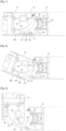
- the tab 101 is likely to be in contact with the housing 201 whatever the position of the opening 20, as shown in particular by figure 3 .
- the body 202 of the second module 200 also comprises ribs 207 extending from the convex wall 205, in a direction substantially parallel to that in which the housing 201 extends. These ribs 207 make it possible on the one hand to adjust the second module 200 in an orifice made in the opening 20 which is intended to receive it and on the other hand to stiffen the body 202 of the latter.
- the second module 200 may advantageously comprise a reinforcing plate 208 arranged at the rear of the housing 201 relative to the body 202, in a recess made in said body 202 and provided for this purpose.
- the reinforcing plate 208 is bent so as to have two branches inclined relative to each other and one of which is fixed to the rear of the flat wall 206 and the other to the rear of the bottom wall 204.
- the tab 101 is configured to extend in the same direction as that in which the housing 201 extends when the opening 20 is closed, so that when said opening 20 is closed, said tab 101 is introduced into said housing 201.
- the tongue 101 extends from a base 102 by which it is intended to be fixed to the frame 30, to a free end whose straight section is rounded so as to promote sliding against one or the other of the curved wall or flat wall 206 of the housing 201, depending on the direction of deformation of the opening 20.
- the tongue 101 comprises two opposite flanks 103 and 104 extending from the base 102 to the free end.
- One of the flanks called the “concave flank” 103, has a substantially concave cross section along an axis parallel to the axis of rotation of the opening 20 and the other flank, called the “flat flank” 104 has a substantially rectilinear cross section.
- the holding and guiding device 10 is configured so that, when the opening 20 is in the closed position, that is to say when the first and second modules 100 and 200 are nested with each other, the concave flank 103 is opposite the convex wall 205 and the flat flank 104 is opposite the flat wall 206.
- the holding and guiding device 10 allows the rotation of the opening 20 relative to the frame 30, while making it possible to correct any possible deformation of the opening 20 when it is closed.
- the tab 101 will gradually bear against one or the other of the convex wall 205 or flat wall 206 of the housing 201, depending on the direction of the deformation of the opening 20, until the latter reaches its closed position.
- the tab 101 When the frame rotates, the tab 101 gradually applies a force to the housing 201, and consequently to the opening leaf 20, opposing the mechanical stresses causing the deformation of the opening leaf 20 so that when it reaches its closed position, said opening leaf 20 exhibits limited deformation in the sense that it has been forced to return to its nominal state or a state close to its nominal state.
- the present invention makes it possible to progressively reduce the deformation of the opening 20 when it is moved towards its closed position.
- the deformation of the opening 20 is limited to the extent of the admissible mechanical clearances, as illustrated in figure 1 .
- the housing 201 is sized so as to allow a relative movement of a few millimeters of the opening 20 relative to the frame 30, for example two millimeters.
- the present invention further constitutes an additional fixing point of the opening 20 relative to the frame 30 when the opening 20 is closed and thus makes it possible to stiffen the opening 20 when it is in the position of closing the bay, so that its resistance to mechanical stresses is increased.
- the deformation of the opening is then also limited when the latter is in the closed position, which guarantees water and air tightness despite the application of constraints on the opening, as well as maintaining the insulation properties, for example thermal, sound, etc.
- the tongue 101 and the body 202 are made from a pair of materials promoting sliding, that is to say minimizing friction.
- the tab 101 may be made of aluminum or aluminum alloy and the body 202 may be made of polyamide.
- the first module 100 may comprise one or more inserts 105 provided to constitute a fixing interface between the latter and the frame upright 30 in which it is intended to be integrated, as illustrated in the Figures 1 to 3 .
- the first module 100 advantageously comprises a seal 110 provided with a longitudinal lip intended to come to bear against the second module 200 and more particularly against a part of the periphery of the opening of the housing 201.
- the lip is opposite a fixing profile to the frame 30 intended to cooperate by complementarity of shape on the one hand with the frame 30 and on the other hand the base 102 of the tongue 101.
- the seal 110 When fixed to the frame 30, the seal 110 is intended to extend in length between two ends at each of which extend means of cooperation with a pre-existing seal 110 known per se to those skilled in the art.
- the seal 110 is configured so that, when the opening 20 is closed, the lip rests against a portion of the periphery of the opening of the housing 201 in order to generate sealing continuity and to allow a significant level of insulation to be maintained.
- the housing 201 is intended to extend in depth into a body 202 in a curvilinear direction substantially orthogonal to the plane defined by the opening 20.
- the housing 201 in this embodiment is consistent with the housing 201 as described previously, with the difference that between its opening and its bottom wall 204, the two facing walls respectively have, on a first portion extending from the bottom wall 204, a convex shape and a concave shape along axes parallel to each other and parallel to the axis of rotation of the opening 20.
- the distance between each of these walls is, for example, approximately constant.
- the facing walls have, on a second portion extending the first portion, a shape such that they move away from each other up to an end delimiting for example the opening of the housing 201.
- the opening of the housing 201 is flared.
- the facing walls are configured to define a contact surface against which the tab 101 is adapted to slide.
- the body 202 may also be provided with ribs extending to the rear of the housing 201 relative to said body 202.
- the second module 200 may further have inserts intended to constitute a fixing interface between the latter and the frame upright 30 in which it is intended to be integrated, as illustrated in the Figures 5 to 7 .
- the tab 101 is configured to extend in the same curvilinear direction as that in which the housing 201 extends when the opening 20 is closed so that when said opening 20 is closed, said tab 101 is introduced into said housing 201.
- the tab 101 has two opposite flanks extending from its base 102 to its free end.
- the opposite flanks respectively have a concave cross section and a convex cross section along an axis parallel to the axis of rotation of the opening 20.
- the side having a concave cross section is intended to be opposite the wall having a convex shape and the side having a convex cross section is intended to be opposite the wall having a concave shape.
- the tab 101 is adapted to be inserted into the housing 201 when closing the opening 20.
- the holding and guiding device 10 allows the rotation of the opening 20 relative to the frame 30, while making it possible to correct any possible deformation of the opening 20 when it is closed.
- the invention has been described by considering walls of the housing 201 constituting a sliding surface having convex and/or concave and/or flat shapes.
- the invention has been described by considering walls of the housing 201 constituting a sliding surface having convex and/or concave and/or flat shapes.
- nothing precludes, in other types of embodiment, considering other types of shapes.
- joinery may comprise a plurality of holding and guiding devices 10 as described above. These devices may be distributed in the most appropriate manner, within the reach of those skilled in the art, along the field of the opening 20 and along the upright of the frame of the dormant 30.
Landscapes
- Engineering & Computer Science (AREA)
- Civil Engineering (AREA)
- Structural Engineering (AREA)
- Wing Frames And Configurations (AREA)
- Specific Sealing Or Ventilating Devices For Doors And Windows (AREA)
- Support Devices For Sliding Doors (AREA)
- Casings For Electric Apparatus (AREA)
Claims (8)
- Halte- und Führungsvorrichtung (10) für Schreinerarbeiten, die einen Flügel (20) umfasst, der entlang einer Drehachse im Verhältnis zu einer Einfassung (30) zwischen einer Öffnungsposition und einer Schließposition angelenkt ist, wobei die Vorrichtung dadurch gekennzeichnet ist, dass sie zwei Module (100, 200) enthält, von denen eines an dem Flügel (20) befestigt werden soll und das andere an einem Höhenschenkel der Einfassung (30), der der Drehachse am nächsten liegt, befestigt werden soll, wobei eines der Module (100, 200), das sogenannte "erste Modul" (100), eine starre Zunge (101) enthält, die in eine Aufnahme (201) mit geradem, aufgeweitetem Querschnitt eingesetzt werden soll, mit der das andere Modul, das sogenannte "zweite Modul" (200), ausgestattet ist, wobei die Aufnahme (201) zwischen zwei Wänden definiert ist, von denen mindestens eine eine konvexe Form, die sogenannte "konvexe Wand" (205), aufweist, wobei sich die konvexe Wand (205) über die Aufnahme (201) hinaus erstreckt, wobei die Module (100, 200) dazu konfiguriert sind, während der Bewegung des Flügels (20) in Richtung seiner Schließposition progressiv miteinander zusammenzuwirken, bis sie, wenn der Flügel (20) seine Schließposition einnimmt, eine Position erreichen, in der sie miteinander verzahnt sind und in der die gesamte Beweglichkeit der Module (100, 200) im Verhältnis zueinander eingeschränkt ist.
- Halte- und Führungsvorrichtung (10) nach Anspruch 1, wobei die Wände der Aufnahme (201) dazu konfiguriert sind, eine Kontaktfläche zu definieren, an der die Zunge (101) gleiten kann.
- Halte- und Führungsvorrichtung (10) nach Anspruch 2, wobei die Zunge (101) ein freies Ende enthält, dessen Querschnitt abgerundet ist und das an einer der gekrümmten Wände der Aufnahme (201) gleiten soll.
- Halte- und Führungsvorrichtung (10) nach einem der Ansprüche 1 bis 3, die eine Dichtung (110) umfasst, die mit einer Längslippe ausgestattet ist, die dazu vorgesehen ist, am zweiten Modul (200) zum Anliegen zu kommen, wobei die Lippe einem Befestigungsprofil des Flügels (20) oder der Einfassung (30) gegenüberliegt, wobei sich die Dichtung (110) in der Länge zwischen zwei Enden erstreckt, an denen sich jeweils Mittel zum Zusammenwirken mit einer bereits vorhandenen Dichtung erstrecken.
- Halte- und Führungsvorrichtung (10) nach einem der Ansprüche 1 bis 4, wobei das zweite Modul (200) einen Körper (202), in dem die Aufnahme (201) ausgebildet ist, und eine Verstärkungsplatte (208) enthält, die hinter der Aufnahme (201) im Verhältnis zum Körper (202) in einer zu diesem Zweck vorgesehenen Vertiefung im Körper (202) angeordnet ist.
- Halte- und Führungsvorrichtung (10) nach einem der Ansprüche 1 bis 5, wobei die Zunge (101) aus Aluminium oder einer Aluminiumlegierung ausgebildet ist.
- Halte- und Führungsvorrichtung (10) nach einem der Ansprüche 1 bis 6, wobei das zweite Modul (200) aus Polyamid ausgebildet ist.
- Schreinerarbeit, die einen Flügel (20) umfasst, der auf der Höhe eines Höhenschenkels einer Einfassung (30) angelenkt ist, die mindestens eine Halte- und Führungsvorrichtung (10) nach einem der Ansprüche 1 bis 7 umfasst, wobei der Flügel (20) und die Einfassung (30) jeweils eine Öffnung enthalten, in der das eine bzw. das andere der Module (100, 200) untergebracht werden sollen.
Applications Claiming Priority (2)
| Application Number | Priority Date | Filing Date | Title |
|---|---|---|---|
| FR1911475A FR3101910B1 (fr) | 2019-10-15 | 2019-10-15 | dispositif de maintien et de guidage d’un ouvrant de menuiserie |
| PCT/EP2020/078916 WO2021074232A1 (fr) | 2019-10-15 | 2020-10-14 | Dispositif de maintien et de guidage d'un ouvrant de menuiserie |
Publications (2)
| Publication Number | Publication Date |
|---|---|
| EP4045751A1 EP4045751A1 (de) | 2022-08-24 |
| EP4045751B1 true EP4045751B1 (de) | 2025-01-29 |
Family
ID=69173030
Family Applications (1)
| Application Number | Title | Priority Date | Filing Date |
|---|---|---|---|
| EP20789170.6A Active EP4045751B1 (de) | 2019-10-15 | 2020-10-14 | Vorrichtung zum halten und führen eines tischlereiöffnungsflügels |
Country Status (5)
| Country | Link |
|---|---|
| EP (1) | EP4045751B1 (de) |
| ES (1) | ES3014413T3 (de) |
| FR (1) | FR3101910B1 (de) |
| PT (1) | PT4045751T (de) |
| WO (1) | WO2021074232A1 (de) |
Family Cites Families (4)
| Publication number | Priority date | Publication date | Assignee | Title |
|---|---|---|---|---|
| DE20215822U1 (de) * | 2002-10-15 | 2003-01-02 | Roto Frank Ag | Beschlag |
| DE202004014552U1 (de) * | 2004-09-16 | 2006-01-26 | Paul Henke Gmbh & Co. Kg | Glastürbeschlag |
| KR101499098B1 (ko) * | 2013-06-14 | 2015-03-06 | 김용호 | 손 끼임 방지기능을 가지는 문짝 |
| FR3069273B1 (fr) * | 2017-07-18 | 2019-08-23 | Sapa As | Menuiserie a ouvrant articule sur pivot et etancheite laterale optimisee |
-
2019
- 2019-10-15 FR FR1911475A patent/FR3101910B1/fr active Active
-
2020
- 2020-10-14 ES ES20789170T patent/ES3014413T3/es active Active
- 2020-10-14 PT PT207891706T patent/PT4045751T/pt unknown
- 2020-10-14 WO PCT/EP2020/078916 patent/WO2021074232A1/fr not_active Ceased
- 2020-10-14 EP EP20789170.6A patent/EP4045751B1/de active Active
Also Published As
| Publication number | Publication date |
|---|---|
| WO2021074232A1 (fr) | 2021-04-22 |
| FR3101910B1 (fr) | 2021-11-05 |
| FR3101910A1 (fr) | 2021-04-16 |
| EP4045751A1 (de) | 2022-08-24 |
| PT4045751T (pt) | 2025-04-16 |
| ES3014413T3 (en) | 2025-04-22 |
Similar Documents
| Publication | Publication Date | Title |
|---|---|---|
| EP2317041B1 (de) | Schloss für Schiebefenster einer Vitrine | |
| FR2926102A1 (fr) | Dispositif de fermeture provisoire d'un element ouvrant sur un element support. | |
| EP2906768B1 (de) | Anordnung mit mindestens zwei transversal oder endmontierbaren platten sowie ihre verwendung zur herstellung eines rahmens für eine tür oder ein fenster | |
| EP4045751B1 (de) | Vorrichtung zum halten und führen eines tischlereiöffnungsflügels | |
| EP2407620B1 (de) | Pfostenprofil für Haltevorrichtung eines schwenkbaren Türflügels, und eine eines solchen Pfosten umfassende Haltevorrichtung | |
| FR3055914A1 (fr) | Dispositif d'entretoisement reglable en longueur | |
| EP2497889B1 (de) | Schiebeflügel mit einem Isolierprofil | |
| FR2986257A1 (fr) | Dispositif de fermeture provisoire d'un element ouvrant sur un element support | |
| FR2957561A1 (fr) | Dispositif de fixation d'une assise de banquette sur un chassis de vehicule automobile, et ensemble comprenant une assise de banquette et un chassis equipe d'au moins un tel dispositif | |
| FR2813624A1 (fr) | Profile de raccord et d'etancheite, dispositif de raccord, panneau a structure sandwich, et ensemble de facade, de cloison ou de couverture | |
| FR2928672A1 (fr) | Dispositif de bardage notamment pour facade ou toiture. | |
| FR2971025A1 (fr) | Dispositif de fixation bord a bord de panneaux | |
| EP2189599B1 (de) | Stulpschiene für ein Schloss, Schloss mit Stulpschiene und Schiebetür mir einem solchen Schloss | |
| FR2656390A1 (fr) | Dispositif de liaison entre deux profiles. | |
| FR2893300A1 (fr) | Dispositif d'ecartement securise a l'arrachement | |
| BE1019911A3 (fr) | Dispositif d'etancheite. | |
| EP3884173A1 (de) | Flexibler profilabschnitt | |
| EP4144941B1 (de) | Einstellbares schliessblech | |
| FR2998606A1 (fr) | Pareclose et dispositif de montage de pareclose | |
| FR3102790A1 (fr) | kit d’accessoire pour menuiserie, menuiserie comportant ledit kit d’accessoire et procédé de mise en œuvre dudit kit d’accessoire sur ladite menuiserie. | |
| FR2951766A1 (fr) | Menuiserie avec vitrage pour baie de batiment, et profils pour la confection d'une feuillure de vitrage | |
| EP4055241B1 (de) | Schwellenvorrichtung, tischlerarbeit, die diese schwellenvorrichtung umfasst, und verfahren zum verwenden dieser schwellenvorrichtung | |
| EP2317061B1 (de) | Pfosten für Türrahmen eines Gebäudes | |
| FR3148265A1 (fr) | Dispositif d’attache | |
| EP2431641A1 (de) | Befestigungsvorrichtung für einen Anschluss eines fluidführenden Rohres an einer Hohlwand |
Legal Events
| Date | Code | Title | Description |
|---|---|---|---|
| STAA | Information on the status of an ep patent application or granted ep patent |
Free format text: STATUS: UNKNOWN |
|
| STAA | Information on the status of an ep patent application or granted ep patent |
Free format text: STATUS: THE INTERNATIONAL PUBLICATION HAS BEEN MADE |
|
| PUAI | Public reference made under article 153(3) epc to a published international application that has entered the european phase |
Free format text: ORIGINAL CODE: 0009012 |
|
| STAA | Information on the status of an ep patent application or granted ep patent |
Free format text: STATUS: REQUEST FOR EXAMINATION WAS MADE |
|
| 17P | Request for examination filed |
Effective date: 20220331 |
|
| AK | Designated contracting states |
Kind code of ref document: A1 Designated state(s): AL AT BE BG CH CY CZ DE DK EE ES FI FR GB GR HR HU IE IS IT LI LT LU LV MC MK MT NL NO PL PT RO RS SE SI SK SM TR |
|
| DAV | Request for validation of the european patent (deleted) | ||
| DAX | Request for extension of the european patent (deleted) | ||
| GRAP | Despatch of communication of intention to grant a patent |
Free format text: ORIGINAL CODE: EPIDOSNIGR1 |
|
| STAA | Information on the status of an ep patent application or granted ep patent |
Free format text: STATUS: GRANT OF PATENT IS INTENDED |
|
| INTG | Intention to grant announced |
Effective date: 20230710 |
|
| GRAJ | Information related to disapproval of communication of intention to grant by the applicant or resumption of examination proceedings by the epo deleted |
Free format text: ORIGINAL CODE: EPIDOSDIGR1 |
|
| STAA | Information on the status of an ep patent application or granted ep patent |
Free format text: STATUS: REQUEST FOR EXAMINATION WAS MADE |
|
| INTC | Intention to grant announced (deleted) | ||
| GRAP | Despatch of communication of intention to grant a patent |
Free format text: ORIGINAL CODE: EPIDOSNIGR1 |
|
| STAA | Information on the status of an ep patent application or granted ep patent |
Free format text: STATUS: GRANT OF PATENT IS INTENDED |
|
| INTG | Intention to grant announced |
Effective date: 20241025 |
|
| GRAS | Grant fee paid |
Free format text: ORIGINAL CODE: EPIDOSNIGR3 |
|
| GRAA | (expected) grant |
Free format text: ORIGINAL CODE: 0009210 |
|
| STAA | Information on the status of an ep patent application or granted ep patent |
Free format text: STATUS: THE PATENT HAS BEEN GRANTED |
|
| AK | Designated contracting states |
Kind code of ref document: B1 Designated state(s): AL AT BE BG CH CY CZ DE DK EE ES FI FR GB GR HR HU IE IS IT LI LT LU LV MC MK MT NL NO PL PT RO RS SE SI SK SM TR |
|
| REG | Reference to a national code |
Ref country code: GB Ref legal event code: FG4D Free format text: NOT ENGLISH |
|
| REG | Reference to a national code |
Ref country code: CH Ref legal event code: EP |
|
| REG | Reference to a national code |
Ref country code: DE Ref legal event code: R096 Ref document number: 602020045543 Country of ref document: DE |
|
| REG | Reference to a national code |
Ref country code: IE Ref legal event code: FG4D Free format text: LANGUAGE OF EP DOCUMENT: FRENCH |
|
| P01 | Opt-out of the competence of the unified patent court (upc) registered |
Free format text: CASE NUMBER: APP_4708/2025 Effective date: 20250128 |
|
| REG | Reference to a national code |
Ref country code: PT Ref legal event code: SC4A Ref document number: 4045751 Country of ref document: PT Date of ref document: 20250416 Kind code of ref document: T Free format text: AVAILABILITY OF NATIONAL TRANSLATION Effective date: 20250408 |
|
| REG | Reference to a national code |
Ref country code: ES Ref legal event code: FG2A Ref document number: 3014413 Country of ref document: ES Kind code of ref document: T3 Effective date: 20250422 |
|
| REG | Reference to a national code |
Ref country code: NL Ref legal event code: MP Effective date: 20250129 |
|
| PG25 | Lapsed in a contracting state [announced via postgrant information from national office to epo] |
Ref country code: NL Free format text: LAPSE BECAUSE OF FAILURE TO SUBMIT A TRANSLATION OF THE DESCRIPTION OR TO PAY THE FEE WITHIN THE PRESCRIBED TIME-LIMIT Effective date: 20250129 |
|
| PG25 | Lapsed in a contracting state [announced via postgrant information from national office to epo] |
Ref country code: RS Free format text: LAPSE BECAUSE OF FAILURE TO SUBMIT A TRANSLATION OF THE DESCRIPTION OR TO PAY THE FEE WITHIN THE PRESCRIBED TIME-LIMIT Effective date: 20250429 |
|
| PG25 | Lapsed in a contracting state [announced via postgrant information from national office to epo] |
Ref country code: FI Free format text: LAPSE BECAUSE OF FAILURE TO SUBMIT A TRANSLATION OF THE DESCRIPTION OR TO PAY THE FEE WITHIN THE PRESCRIBED TIME-LIMIT Effective date: 20250129 |
|
| PG25 | Lapsed in a contracting state [announced via postgrant information from national office to epo] |
Ref country code: PL Free format text: LAPSE BECAUSE OF FAILURE TO SUBMIT A TRANSLATION OF THE DESCRIPTION OR TO PAY THE FEE WITHIN THE PRESCRIBED TIME-LIMIT Effective date: 20250129 |
|
| REG | Reference to a national code |
Ref country code: LT Ref legal event code: MG9D |
|
| PG25 | Lapsed in a contracting state [announced via postgrant information from national office to epo] |
Ref country code: NO Free format text: LAPSE BECAUSE OF FAILURE TO SUBMIT A TRANSLATION OF THE DESCRIPTION OR TO PAY THE FEE WITHIN THE PRESCRIBED TIME-LIMIT Effective date: 20250429 Ref country code: IS Free format text: LAPSE BECAUSE OF FAILURE TO SUBMIT A TRANSLATION OF THE DESCRIPTION OR TO PAY THE FEE WITHIN THE PRESCRIBED TIME-LIMIT Effective date: 20250529 |
|
| REG | Reference to a national code |
Ref country code: AT Ref legal event code: MK05 Ref document number: 1763593 Country of ref document: AT Kind code of ref document: T Effective date: 20250129 |
|
| PG25 | Lapsed in a contracting state [announced via postgrant information from national office to epo] |
Ref country code: HR Free format text: LAPSE BECAUSE OF FAILURE TO SUBMIT A TRANSLATION OF THE DESCRIPTION OR TO PAY THE FEE WITHIN THE PRESCRIBED TIME-LIMIT Effective date: 20250129 |
|
| PG25 | Lapsed in a contracting state [announced via postgrant information from national office to epo] |
Ref country code: LV Free format text: LAPSE BECAUSE OF FAILURE TO SUBMIT A TRANSLATION OF THE DESCRIPTION OR TO PAY THE FEE WITHIN THE PRESCRIBED TIME-LIMIT Effective date: 20250129 |
|
| PG25 | Lapsed in a contracting state [announced via postgrant information from national office to epo] |
Ref country code: BG Free format text: LAPSE BECAUSE OF FAILURE TO SUBMIT A TRANSLATION OF THE DESCRIPTION OR TO PAY THE FEE WITHIN THE PRESCRIBED TIME-LIMIT Effective date: 20250129 Ref country code: GR Free format text: LAPSE BECAUSE OF FAILURE TO SUBMIT A TRANSLATION OF THE DESCRIPTION OR TO PAY THE FEE WITHIN THE PRESCRIBED TIME-LIMIT Effective date: 20250430 |
|
| PG25 | Lapsed in a contracting state [announced via postgrant information from national office to epo] |
Ref country code: AT Free format text: LAPSE BECAUSE OF FAILURE TO SUBMIT A TRANSLATION OF THE DESCRIPTION OR TO PAY THE FEE WITHIN THE PRESCRIBED TIME-LIMIT Effective date: 20250129 |
|
| PG25 | Lapsed in a contracting state [announced via postgrant information from national office to epo] |
Ref country code: SE Free format text: LAPSE BECAUSE OF FAILURE TO SUBMIT A TRANSLATION OF THE DESCRIPTION OR TO PAY THE FEE WITHIN THE PRESCRIBED TIME-LIMIT Effective date: 20250129 |
|
| PG25 | Lapsed in a contracting state [announced via postgrant information from national office to epo] |
Ref country code: SM Free format text: LAPSE BECAUSE OF FAILURE TO SUBMIT A TRANSLATION OF THE DESCRIPTION OR TO PAY THE FEE WITHIN THE PRESCRIBED TIME-LIMIT Effective date: 20250129 |
|
| PG25 | Lapsed in a contracting state [announced via postgrant information from national office to epo] |
Ref country code: DK Free format text: LAPSE BECAUSE OF FAILURE TO SUBMIT A TRANSLATION OF THE DESCRIPTION OR TO PAY THE FEE WITHIN THE PRESCRIBED TIME-LIMIT Effective date: 20250129 |
|
| PG25 | Lapsed in a contracting state [announced via postgrant information from national office to epo] |
Ref country code: CZ Free format text: LAPSE BECAUSE OF FAILURE TO SUBMIT A TRANSLATION OF THE DESCRIPTION OR TO PAY THE FEE WITHIN THE PRESCRIBED TIME-LIMIT Effective date: 20250129 Ref country code: EE Free format text: LAPSE BECAUSE OF FAILURE TO SUBMIT A TRANSLATION OF THE DESCRIPTION OR TO PAY THE FEE WITHIN THE PRESCRIBED TIME-LIMIT Effective date: 20250129 |
|
| PG25 | Lapsed in a contracting state [announced via postgrant information from national office to epo] |
Ref country code: RO Free format text: LAPSE BECAUSE OF FAILURE TO SUBMIT A TRANSLATION OF THE DESCRIPTION OR TO PAY THE FEE WITHIN THE PRESCRIBED TIME-LIMIT Effective date: 20250129 |
|
| PG25 | Lapsed in a contracting state [announced via postgrant information from national office to epo] |
Ref country code: SK Free format text: LAPSE BECAUSE OF FAILURE TO SUBMIT A TRANSLATION OF THE DESCRIPTION OR TO PAY THE FEE WITHIN THE PRESCRIBED TIME-LIMIT Effective date: 20250129 |
|
| REG | Reference to a national code |
Ref country code: DE Ref legal event code: R097 Ref document number: 602020045543 Country of ref document: DE |
|
| PLBE | No opposition filed within time limit |
Free format text: ORIGINAL CODE: 0009261 |
|
| STAA | Information on the status of an ep patent application or granted ep patent |
Free format text: STATUS: NO OPPOSITION FILED WITHIN TIME LIMIT |
|
| 26N | No opposition filed |
Effective date: 20251030 |