EP4043337B1 - Flügeldemontageanordnung und flugzeug - Google Patents
Flügeldemontageanordnung und flugzeug Download PDFInfo
- Publication number
- EP4043337B1 EP4043337B1 EP20859994.4A EP20859994A EP4043337B1 EP 4043337 B1 EP4043337 B1 EP 4043337B1 EP 20859994 A EP20859994 A EP 20859994A EP 4043337 B1 EP4043337 B1 EP 4043337B1
- Authority
- EP
- European Patent Office
- Prior art keywords
- wing
- press
- fitting
- fastening
- vehicle body
- Prior art date
- Legal status (The legal status is an assumption and is not a legal conclusion. Google has not performed a legal analysis and makes no representation as to the accuracy of the status listed.)
- Active
Links
Images


Classifications
-
- B—PERFORMING OPERATIONS; TRANSPORTING
- B64—AIRCRAFT; AVIATION; COSMONAUTICS
- B64U—UNMANNED AERIAL VEHICLES [UAV]; EQUIPMENT THEREFOR
- B64U10/00—Type of UAV
- B64U10/25—Fixed-wing aircraft
-
- B—PERFORMING OPERATIONS; TRANSPORTING
- B64—AIRCRAFT; AVIATION; COSMONAUTICS
- B64U—UNMANNED AERIAL VEHICLES [UAV]; EQUIPMENT THEREFOR
- B64U30/00—Means for producing lift; Empennages; Arrangements thereof
- B64U30/10—Wings
- B64U30/12—Variable or detachable wings, e.g. wings with adjustable sweep
-
- B—PERFORMING OPERATIONS; TRANSPORTING
- B64—AIRCRAFT; AVIATION; COSMONAUTICS
- B64C—AEROPLANES; HELICOPTERS
- B64C2211/00—Modular constructions of airplanes or helicopters
Definitions
- the present application relates to the field of aerial vehicle technologies, and in particular, to a wing detachment assembly and an aerial vehicle.
- An aerial vehicle may provide people with entertainment or may perform a task for people.
- the aerial vehicle may be used as an important tool for high-altitude photography.
- the aerial vehicle includes a wing and a vehicle body.
- the aerial vehicle may occupy a relatively large space due to such a relatively long wing. Accordingly, an aerial vehicle having a detachable wing has emerged.
- an existing solution for detaching and mounting the wing of the aerial vehicle is relatively inconvenient and requires a dedicated detachment tool.
- a conventional wing detachment assembly is disclosed in some patent documents, for example, the patent application Pub. No. US2018/327093Al , the patent application Pub. No. CN207482173U , the patent application Pub. No. CN109515706A , and the patent application Pub. No. US2018/086458Al .
- the present application is mainly intended to provide a wing detachment assembly and an aerial vehicle, to resolve an existing technical problem that a solution for detaching and mounting a wing of an aerial vehicle is relatively inconvenient.
- the present application provides a wing detachment assembly as defined by the appended set of claims.
- the fastening member includes a fastening connection rod, the fastening body is disposed on one end of the fastening connection rod, and an other end of the fastening connection rod is rotatably connected to the press-fitting member.
- the fastening body is spherical or cylindrical.
- a middle portion of the press-fitting member is rotatably connected to the fastening member.
- the press-fitting member includes a press-fitting connection rod and a press-fitting handle, an end of the press-fitting connection rod being rotatably connected to the fixing base, an other end of the press-fitting connection rod being fixedly connected to the press-fitting handle and the press-fitting connection rod and the press-fitting handle being located on different straight lines.
- the mounting groove includes a groove bottom and a groove wall, the groove bottom and the groove wall being connected to form an arc surface.
- the wing detachment assembly further includes a buckling member configured to fix the press-fitting member, the buckling member fixing the press-fitting member when the fastening member is fastened in the mounting groove.
- the second connecting portion includes a connecting base and a second connecting plate, the mounting groove being provided on the connecting base, the second connecting plate being fixedly connected to the connecting base and the second connecting plate being configured to be fixed on an inner wall of a housing of the vehicle body or the wing.
- the connecting base When the second connecting portion is fixed on the vehicle body, the connecting base passes through the housing of the vehicle body to enable the mounting groove to be exposed from the housing of the vehicle body; or when the second connecting portion is fixed on the wing, the connecting base passes through the housing of the wing to enable the mounting groove to be exposed from the housing of the wing.
- the present application further provides an aerial vehicle.
- the aerial vehicle includes a vehicle body, a wing and the foregoing wing detachment assembly.
- the wing is detachably connected to the vehicle body by using the wing detachment assembly.
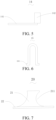
- the present application provides a wing detachment assembly 1 configured to detachably connect a wing of an aerial vehicle to a vehicle body of the aerial vehicle.
- the wing detachment assembly 1 includes a first connecting portion 10 and a second connecting portion 20.
- the first connecting portion 10 and the second connecting portion 20 can be quickly detached and connected.
- One of the first connecting portion 10 and the second connecting portion 20 is fixed to the wing and the other is fixed to the vehicle body.
- the description is made by using an example in which the first connecting portion 10 is fixed on the vehicle body and the second connecting portion 20 is fixed on the wing.
- the first connecting portion 10 includes a first connecting plate 11, a fixing base 12, a press-fitting member 13, a fastening member 14 and a buckling member 15.
- the first connecting plate 11 is fixedly connected to the fixing base 12.
- the press-fitting member 13 is rotatably connected to the fixing base 12.
- the fastening member 14 is rotatably connected to the press-fitting member 13.
- the first connecting plate 11 is configured to be fixed on the vehicle body.
- An end of the fastening member 14 is configured to be fastened to the second connecting portion 20.
- the press-fitting member 13 is press-fitted under the action of an external force to drive the fastening member 14 to be far away from the second connecting portion 20 as a whole.
- the fastening member 14 is fixed to the second connecting portion 20.
- the buckling member 15 is configured to be fixed to the press-fitting member 13.
- the press-fitting member 13 is fixed to the vehicle body, so that the connection between the first connecting portion 10 and the second connecting portion 20 is more stable. It is to be understood that the configuration of the buckling member 15 may be omitted.
- a shape of the first connecting plate 11 is not limited.
- the first connecting plate 11 may be circular or quadrilateral.
- the first connecting plate 11 is fixed on an inner wall of a housing of the vehicle body.
- the fixing base 12 passes through the housing of the vehicle body to be rotatably connected to the press-fitting member 13.
- the first connecting plate 11 is firmly fixed on the inner wall of the housing, which is not prone to falling.
- the first connecting plate 11 may be adhered to the inner wall of the housing of the vehicle body.
- An area of the first connecting plate 11 is set according to requirements. When the area of the first connecting plate 11 is large, a pressure on the housing of the vehicle body is relatively small. Therefore, the housing of the vehicle body is not necessarily configured to be excessively thick.
- a specific structure for rotatably connecting the fixing base 12 and the press-fitting member 13 is not limited.
- the connection may be implemented by using a hinge structure, a rotating shaft structure or a pin structure.
- the fixing base 12 and the first connecting plate 11 may be integrally formed. It is to be understood that a structure for rotatably connecting other two components is also not limited.
- an end of the press-fitting member 13 is rotatably connected to the fixing base 12 and a middle portion of the press-fitting member 13 is rotatably connected to the fastening member 14.
- a distance between the middle portion and the end of the press-fitting member 13 is greater than one third of a length of the press-fitting member 13.
- a distance between the middle portion and an other end of the press-fitting member 13 is less than two-thirds of length of the press-fitting member 13.
- the press-fitting member 13 includes a press-fitting connection rod 131 and a press-fitting handle 132. An end of the press-fitting connection rod 131 is rotatably connected to the fixing base 12.
- the press-fitting connection rod 131 is fixedly connected to the press-fitting handle 132.
- the press-fitting connection rod 131 and the press-fitting handle 132 are located on different straight lines.
- the press-fitting handle 132 helps a user apply a force to the press-fitting member 13 during detachment and mounting of the wing.
- the press-fitting connection rod 131 and the press-fitting handle 132 may be integrally formed.
- the fastening member 14 includes a fastening connection rod 141 and a fastening body 142 disposed on one end of the fastening connection rod 141.
- An other end of the fastening connection rod 141 is rotatably connected to the press-fitting member 13.
- the fastening connection rod 141 and the fastening body 142 are located on different planes, so that the fastening body 142 can be fastened to the second connecting portion 20.
- the fastening connection rod 141 is rod-shaped.
- a cross-sectional area of the fastening connection rod 141 is not limited.
- the cross-sectional area may be circular or quadrilateral.
- the fastening body 142 is spherical or cylindrical, which can be better in contact with the second connecting portion 20.
- an end portion of the cylinder is connected to a side wall of the fastening connection rod 141.
- the buckling member 15 is U-shaped.
- a middle portion of the buckling member 15 is configured to fasten the press-fitting member 13.
- Two ends of the buckling member 15 are configured to be fixed on the vehicle body.
- a hole or a groove may be provided on the vehicle body for fixing.
- protrusions 151 are respectively disposed on outer sides of the two ends of the U-shaped buckling member 15 to be engaged with the vehicle body.
- the second connecting portion 20 includes a connecting base 21 and a second connecting plate 22.
- the connecting base 21 is fixedly connected to the second connecting plate 22.
- the second connecting plate 22 is configured to be fixed on the wing.
- the connecting base 21 is configured for fixing of the fastening member 14.
- a shape of the second connecting plate 22 is not limited.
- the second connecting plate 22 may be circular or quadrilateral.
- the second connecting plate 22 is fixed on an inner wall of a housing of the wing.
- the connecting base 21 passes through the housing of the vehicle body to be connected to the fastening member 14.
- the second connecting plate 22 is firmly fixed on the inner wall of the housing of the wing, which is not prone to falling.
- the second connecting plate 22 may be adhered to the inner wall of the housing of the wing.
- An area of the second connecting plate 22 is set according to requirements. When the area of the second connecting plate 22 is large, a pressure on the housing of the wing is relatively small. Therefore, the housing of the wing is not necessarily configured to be excessively thick.
- the second connecting plate 22 may alternatively be fixed on an outer wall of the housing of the wing or embedded in the housing of the wing.
- a mounting groove 211 is provided on the connecting base 21.
- a notch of the mounting groove 211 is provided away from the first connecting portion 10.
- the press-fitting member 13 is press-fitted to drive the fastening member 14 to be far away from the notch of the mounting groove 211 as a whole.
- the fastening body 142 of the fastening member 14 is fastened in the mounting groove 211.
- the fastening body 142 is fixed in the mounting groove 211.
- the configuration of the second connecting plate 22 may be omitted, so that the connecting base 21 is fixed on the wing.
- the mounting groove 211 includes a groove bottom and a groove wall.
- the groove bottom and the groove wall are connected to form an arc surface. Therefore, the fastening body 142 may be easier to be fixed in the mounting groove 211.
- a shape of the mounting groove 211 is not limited in the present application.
- the mounting groove 211 may alternatively be a V-shaped groove.
- the first connecting plate 11 of the first connecting portion 10 is fixed on the inner wall of the housing of the vehicle body and the second connecting plate 22 of the second connecting portion 20 is fixed on the inner wall of the housing of the wing.
- the press-fitting member 13 is rotated and the fastening body 142 of the fastening member 14 is disposed in the mounting groove 211. Then, the press-fitting member 13 is rotated again, so that the fastening member 14 is far away from the notch of the mounting groove 211 as a whole and the fastening body 142 is pressed on the groove bottom of the mounting groove 211.
- the buckling member 15 fixes the press-fitting member 13 on the vehicle body when the fastening member 14 is fastened in the mounting groove 211.
- the wing is mounted on the vehicle body. It is to be understood that, when one aerial vehicle includes two wings, two wing detachment assemblies are required for quickly detaching each wing. It is to be understood that the wing may be detached by inversely performing the foregoing operation.
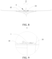
- the present application further provides an aerial vehicle 2.
- the aerial vehicle 2 includes a vehicle body 30, a wing 40 and the foregoing wing detachment assembly 1.
- the wing 40 is detachably connected to the vehicle body 30 by using the wing detachment assembly 1.
- the aerial vehicle 2 may be a flight device such as an unmanned aerial vehicle.
Landscapes
- Engineering & Computer Science (AREA)
- Mechanical Engineering (AREA)
- Aviation & Aerospace Engineering (AREA)
- Remote Sensing (AREA)
- Connection Of Plates (AREA)
- Forklifts And Lifting Vehicles (AREA)
- Pivots And Pivotal Connections (AREA)
Claims (9)
- Flügeldemontageanordnung (1), die zum lösbaren Verbinden eines Flügels (40) eines Luftfahrzeugs (2) mit einem Fahrzeughauptteil (30) des Luftfahrzeugs (2) geeignet ist, wobei die Flügeldemontageanordnung (1) einen ersten Verbindungsabschnitt (10) und einen zweiten Verbindungsabschnitt (20) umfasst, wobei der erste Verbindungsabschnitt (10) einen Fixiersockel (12), ein Einpresselement (13) und ein Befestigungselement (14) umfasst, wobei von dem Fixiersockel (12) und dem zweiten Verbindungsabschnitt (20) einer dazu ausgestaltet ist, am Flügel (40) fixiert zu werden, und der andere dazu ausgestaltet ist, am Fahrzeughauptteil (30) fixiert zu werden;eine Montagenut (211) am zweiten Verbindungsabschnitt (20) vorgesehen ist, wobei die Montagenut (211) eine Kerbe umfasst, die im Gebrauch distal zum ersten Verbindungsabschnitt (10) liegt; unddas Einpresselement (13) drehbar mit dem Fixiersockel (12) verbunden ist, das Befestigungselement (14) drehbar mit dem Einpresselement (13) verbunden ist, ein Ende des Befestigungselements (14) dazu ausgestaltet ist, in die Kerbe einzugreifen, und das Einpresselement (13) dazu ausgestaltet ist, bei Betätigung die drehbare Verbindung des Befestigungselements (14) mit dem Einpresselement (13) derart in eine Position distal zur Kerbe zu bringen, dass ein Befestigungshauptteil (142) am Ende des Befestigungselements (14) in die Kerbe gedrängt wird;der erste Verbindungsabschnitt (10) ferner eine erste Verbindungsplatte (11) umfasst, wobei die erste Verbindungsplatte (11) fest mit dem Fixiersockel (12) verbunden ist;dadurch gekennzeichnet, dassdie erste Verbindungsplatte (11), damit sich der Fixiersockel (12) am Fahrzeughauptteil (30) fixieren lässt, dazu ausgestaltet ist, derart an einer Innenwand eines Gehäuses des Fahrzeughauptteils (30) fixiert zu werden, dass der Fixiersockel (12) durch das Gehäuse des Fahrzeughauptteils (30) verläuft, um drehbar mit dem Einpresselement (13) verbunden zu werden; oderdie erste Verbindungsplatte (11), damit sich der Fixiersockel (12) am Flügel (40) fixieren lässt, dazu ausgestaltet ist, derart an einer Innenwand eines Gehäuses des Flügels (40) fixiert zu werden, dass der Fixiersockel (12) durch das Gehäuse des Flügels (40) verläuft, um drehbar mit dem Einpresselement (13) verbunden zu werden.
- Flügeldemontageanordnung (1) nach Anspruch 1, dadurch gekennzeichnet, dass das Befestigungselement (14) eine Befestigungs- und Verbindungsstange (141) umfasst und der Befestigungshauptteil (142) an einem Ende der Befestigungs- und Verbindungsstange (141) angeordnet ist, während ein anderes Ende der Befestigungs- und Verbindungsstange (141) drehbar mit dem Festpresselement (13) verbunden ist.
- Flügeldemontageanordnung (1) nach Anspruch 2, dadurch gekennzeichnet, dass der Befestigungshauptteil (142) kugelförmig oder zylindrisch ist.
- Flügeldemontageanordnung (1) nach Anspruch 1, dadurch gekennzeichnet, dass ein mittlerer Abschnitt des Festpresselements (13) drehbar mit dem Befestigungselement (14) verbunden ist.
- Flügeldemontageanordnung (1) nach Anspruch 1, dadurch gekennzeichnet, dass das Einpresselement (13) eine Einpress-Verbindungsstange (131) und einen Einpressgriff (132) umfasst, wobei ein Ende der Einpress-Verbindungsstange (131) drehbar mit dem Fixiersockel (12) verbunden ist, wobei ein anderes Ende der Einpress-Verbindungsstange (131) fest mit dem Einpressgriff (132) verbunden ist und sich die Einpress-Verbindungsstange (131) und der Einpressgriff (132) auf unterschiedlichen geraden Linien befinden.
- Flügeldemontageanordnung (1) nach Anspruch 1, dadurch gekennzeichnet, dass die Montagenut (211) einen Nutboden und eine Nutwand umfasst, wobei der Nutboden und die Nutwand so verbunden sind, dass sie eine Bogenfläche bilden.
- Flügeldemontageanordnung (1) nach Anspruch 1, dadurch gekennzeichnet, dass die Flügeldemontageanordnung (1) ferner ein Knickelement (15) umfasst, das dazu ausgestaltet ist, das Festpresselement (13) zu fixieren, wobei das Knickelement (15) das Festpresselement (13) fixiert, wenn das Befestigungselement (14) in der Montagenut (211) befestigt ist.
- Flügeldemontageanordnung (1) nach Anspruch 1, dadurch gekennzeichnet, dass der zweite Verbindungsabschnitt (20) einen Verbindungssockel (21) und eine zweite Verbindungsplatte (22) umfasst, wobei die Montagenut (211) an dem Verbindungssockel (21) vorgesehen ist, wobei die zweite Verbindungsplatte (22) fest mit dem Verbindungssockel (21) verbunden ist und die zweite Verbindungsplatte (22) dazu ausgestaltet ist, an einer Innenwand eines Gehäuses des Fahrzeughauptteils (30) oder des Flügels (40) fixiert zu werden;der Verbindungssockel (21), wenn der zweite Verbindungsabschnitt (20) am Fahrzeughauptteil (30) fixiert ist, durch das Gehäuse des Fahrzeughauptteils (30) verläuft und so die Montagenut (211) aus dem Gehäuse des Fahrzeughauptteils (30) sichtbar werden lässt; oderder Verbindungssockel (21), wenn der zweite Verbindungsabschnitt (20) am Flügel (40) fixiert ist, durch das Gehäuse des Flügels (40) verläuft und so die Montagenut (211) aus dem Gehäuse des Flügels (40) sichtbar werden lässt.
- Luftfahrzeug (2), umfassend:einen Fahrzeughauptteil (30);einen Flügel (40); unddie Flügeldemontageanordnung (1) nach einem der Ansprüche 1 bis 8, wobei der Flügel (40) unter Verwendung der Flügeldemontageanordnung (1) lösbar mit dem Fahrzeughauptteil (30) verbunden ist.
Applications Claiming Priority (2)
| Application Number | Priority Date | Filing Date | Title |
|---|---|---|---|
| CN201921474701.3U CN211196589U (zh) | 2019-09-05 | 2019-09-05 | 机翼拆卸组件和飞行器 |
| PCT/CN2020/123359 WO2021043335A2 (zh) | 2019-09-05 | 2020-10-23 | 机翼拆卸组件和飞行器 |
Publications (3)
| Publication Number | Publication Date |
|---|---|
| EP4043337A2 EP4043337A2 (de) | 2022-08-17 |
| EP4043337A4 EP4043337A4 (de) | 2023-01-18 |
| EP4043337B1 true EP4043337B1 (de) | 2025-03-05 |
Family
ID=71880953
Family Applications (1)
| Application Number | Title | Priority Date | Filing Date |
|---|---|---|---|
| EP20859994.4A Active EP4043337B1 (de) | 2019-09-05 | 2020-10-23 | Flügeldemontageanordnung und flugzeug |
Country Status (4)
| Country | Link |
|---|---|
| US (1) | US20220185445A1 (de) |
| EP (1) | EP4043337B1 (de) |
| CN (1) | CN211196589U (de) |
| WO (1) | WO2021043335A2 (de) |
Families Citing this family (1)
| Publication number | Priority date | Publication date | Assignee | Title |
|---|---|---|---|---|
| CN211196589U (zh) * | 2019-09-05 | 2020-08-07 | 深圳市道通智能航空技术有限公司 | 机翼拆卸组件和飞行器 |
Family Cites Families (13)
| Publication number | Priority date | Publication date | Assignee | Title |
|---|---|---|---|---|
| GB0116219D0 (en) * | 2001-07-03 | 2002-03-06 | Bae Systems Plc | An aircraft |
| CN106005370A (zh) * | 2016-08-03 | 2016-10-12 | 南昌白龙马航空科技有限公司 | 无人机机翼快拆装置 |
| IL247772B (en) * | 2016-09-12 | 2022-05-01 | Israel Aerospace Ind Ltd | Model car system |
| US11014666B2 (en) * | 2016-09-23 | 2021-05-25 | Skydio, Inc. | Airframe |
| CN206125394U (zh) * | 2016-10-12 | 2017-04-26 | 深圳市鼎点航模有限公司 | 机翼固定结构及无人机 |
| CN206437190U (zh) * | 2016-11-24 | 2017-08-25 | 上海拓攻机器人有限公司 | 一种连接结构及无人飞行器机架 |
| US10988257B2 (en) * | 2017-05-11 | 2021-04-27 | Hood Technology Corporation | Aircraft-retrieval system |
| CN206984303U (zh) * | 2017-07-28 | 2018-02-09 | 东海县腾翔航空科技有限公司 | 一种分体式无人机 |
| CN207482173U (zh) * | 2017-09-11 | 2018-06-12 | 珠海天晴航空航天科技有限公司 | 一种机身机翼连接结构及锁紧装置 |
| CN108394548A (zh) * | 2018-03-13 | 2018-08-14 | 珠海天晴航空航天科技有限公司 | 一种飞翼式无人机 |
| CN109436292A (zh) * | 2018-11-02 | 2019-03-08 | 海空天科技股份有限公司 | 一种无人机机翼快速拆装的机构及无人机 |
| CN109515706A (zh) * | 2018-12-03 | 2019-03-26 | 成都纵横大鹏无人机科技有限公司 | 一种模块化无人机 |
| CN211196589U (zh) * | 2019-09-05 | 2020-08-07 | 深圳市道通智能航空技术有限公司 | 机翼拆卸组件和飞行器 |
-
2019
- 2019-09-05 CN CN201921474701.3U patent/CN211196589U/zh active Active
-
2020
- 2020-10-23 WO PCT/CN2020/123359 patent/WO2021043335A2/zh not_active Ceased
- 2020-10-23 EP EP20859994.4A patent/EP4043337B1/de active Active
-
2022
- 2022-03-04 US US17/653,525 patent/US20220185445A1/en not_active Abandoned
Also Published As
| Publication number | Publication date |
|---|---|
| EP4043337A4 (de) | 2023-01-18 |
| WO2021043335A3 (zh) | 2021-04-22 |
| WO2021043335A2 (zh) | 2021-03-11 |
| EP4043337A2 (de) | 2022-08-17 |
| US20220185445A1 (en) | 2022-06-16 |
| CN211196589U (zh) | 2020-08-07 |
Similar Documents
| Publication | Publication Date | Title |
|---|---|---|
| US11155335B2 (en) | Driving device, propeller and propulsion system | |
| EP3840111B1 (de) | Unbemanntes luftfahrzeug mit batterie | |
| US20190050028A1 (en) | Hinge structure, electronic device and assembling method of hinge structure | |
| EP3070399B1 (de) | Vorrichtung zur sicherung einer led-lichtquelle an einer kühlkörperoberfläche | |
| US20050265132A1 (en) | Connection structure for a watchcase with a watch chain | |
| EP4043337B1 (de) | Flügeldemontageanordnung und flugzeug | |
| KR101138501B1 (ko) | 소형 무인 항공기용 날개 연결 장치 | |
| WO2018058771A1 (zh) | 电池卡合机构、电池和无人机以及充电装置 | |
| WO2018113480A1 (zh) | 可拆卸机臂组件及飞行器 | |
| BRPI0517656A (pt) | conjunto conector para aeronave | |
| US9692148B2 (en) | Connection terminal | |
| EP4023548B1 (de) | Flügelabnahmeanordnung und flugzeug | |
| US9195270B2 (en) | Display device for notebook computer | |
| CN210258808U (zh) | 一种无人机快拆机臂 | |
| CN110757516B (zh) | 剃须刀及刀头浮动结构 | |
| US20210094689A1 (en) | Frame and uav | |
| CN210310912U (zh) | 支撑架装配结构 | |
| CN217143818U (zh) | 一种孔轴两用式卡簧钳 | |
| JPH1096429A (ja) | 板ばねカップリング | |
| CN209938926U (zh) | 一种用于无人机的新型机架 | |
| CN211281470U (zh) | 一种机翼快拆结构及无人机 | |
| JP3060737U (ja) | ファイル | |
| CN207253767U (zh) | 一种航模的机翼连接结构 | |
| US6317926B1 (en) | Fixing device for LCD unit | |
| EP1612138A1 (de) | Paneelhalterung in einem Flugzeug |
Legal Events
| Date | Code | Title | Description |
|---|---|---|---|
| STAA | Information on the status of an ep patent application or granted ep patent |
Free format text: STATUS: THE INTERNATIONAL PUBLICATION HAS BEEN MADE |
|
| PUAI | Public reference made under article 153(3) epc to a published international application that has entered the european phase |
Free format text: ORIGINAL CODE: 0009012 |
|
| STAA | Information on the status of an ep patent application or granted ep patent |
Free format text: STATUS: REQUEST FOR EXAMINATION WAS MADE |
|
| 17P | Request for examination filed |
Effective date: 20220331 |
|
| AK | Designated contracting states |
Kind code of ref document: A2 Designated state(s): AL AT BE BG CH CY CZ DE DK EE ES FI FR GB GR HR HU IE IS IT LI LT LU LV MC MK MT NL NO PL PT RO RS SE SI SK SM TR |
|
| XX | Miscellaneous (additional remarks) |
Free format text: A REQUEST FOR RESTORATION OF THE RIGHT OF PRIORITY BY THE EPO AS DESIGNATED OFFICE HAS BEEN GRANTED (R. 49TER.2 PCT, ART.122 EPC. |
|
| DAV | Request for validation of the european patent (deleted) | ||
| DAX | Request for extension of the european patent (deleted) | ||
| A4 | Supplementary search report drawn up and despatched |
Effective date: 20221219 |
|
| RIC1 | Information provided on ipc code assigned before grant |
Ipc: B64C 3/00 20060101ALI20221213BHEP Ipc: B64C 1/26 20060101AFI20221213BHEP |
|
| STAA | Information on the status of an ep patent application or granted ep patent |
Free format text: STATUS: EXAMINATION IS IN PROGRESS |
|
| 17Q | First examination report despatched |
Effective date: 20240614 |
|
| GRAP | Despatch of communication of intention to grant a patent |
Free format text: ORIGINAL CODE: EPIDOSNIGR1 |
|
| STAA | Information on the status of an ep patent application or granted ep patent |
Free format text: STATUS: GRANT OF PATENT IS INTENDED |
|
| INTG | Intention to grant announced |
Effective date: 20241105 |
|
| GRAS | Grant fee paid |
Free format text: ORIGINAL CODE: EPIDOSNIGR3 |
|
| GRAA | (expected) grant |
Free format text: ORIGINAL CODE: 0009210 |
|
| STAA | Information on the status of an ep patent application or granted ep patent |
Free format text: STATUS: THE PATENT HAS BEEN GRANTED |
|
| AK | Designated contracting states |
Kind code of ref document: B1 Designated state(s): AL AT BE BG CH CY CZ DE DK EE ES FI FR GB GR HR HU IE IS IT LI LT LU LV MC MK MT NL NO PL PT RO RS SE SI SK SM TR |
|
| REG | Reference to a national code |
Ref country code: GB Ref legal event code: FG4D |
|
| XX | Miscellaneous (additional remarks) |
Free format text: A REQUEST FOR RESTORATION OF THE RIGHT OF PRIORITY BY THE EPO AS DESIGNATED OFFICE HAS BEEN GRANTED (R. 49TER.2 PCT, ART.122 EPC |
|
| REG | Reference to a national code |
Ref country code: CH Ref legal event code: EP |
|
| REG | Reference to a national code |
Ref country code: DE Ref legal event code: R096 Ref document number: 602020047381 Country of ref document: DE |
|
| REG | Reference to a national code |
Ref country code: IE Ref legal event code: FG4D |
|
| PG25 | Lapsed in a contracting state [announced via postgrant information from national office to epo] |
Ref country code: RS Free format text: LAPSE BECAUSE OF FAILURE TO SUBMIT A TRANSLATION OF THE DESCRIPTION OR TO PAY THE FEE WITHIN THE PRESCRIBED TIME-LIMIT Effective date: 20250605 |
|
| PG25 | Lapsed in a contracting state [announced via postgrant information from national office to epo] |
Ref country code: FI Free format text: LAPSE BECAUSE OF FAILURE TO SUBMIT A TRANSLATION OF THE DESCRIPTION OR TO PAY THE FEE WITHIN THE PRESCRIBED TIME-LIMIT Effective date: 20250305 |
|
| REG | Reference to a national code |
Ref country code: NL Ref legal event code: MP Effective date: 20250305 |
|
| PG25 | Lapsed in a contracting state [announced via postgrant information from national office to epo] |
Ref country code: ES Free format text: LAPSE BECAUSE OF FAILURE TO SUBMIT A TRANSLATION OF THE DESCRIPTION OR TO PAY THE FEE WITHIN THE PRESCRIBED TIME-LIMIT Effective date: 20250305 |
|
| REG | Reference to a national code |
Ref country code: LT Ref legal event code: MG9D |
|
| PG25 | Lapsed in a contracting state [announced via postgrant information from national office to epo] |
Ref country code: NO Free format text: LAPSE BECAUSE OF FAILURE TO SUBMIT A TRANSLATION OF THE DESCRIPTION OR TO PAY THE FEE WITHIN THE PRESCRIBED TIME-LIMIT Effective date: 20250605 |
|
| PG25 | Lapsed in a contracting state [announced via postgrant information from national office to epo] |
Ref country code: HR Free format text: LAPSE BECAUSE OF FAILURE TO SUBMIT A TRANSLATION OF THE DESCRIPTION OR TO PAY THE FEE WITHIN THE PRESCRIBED TIME-LIMIT Effective date: 20250305 |
|
| PG25 | Lapsed in a contracting state [announced via postgrant information from national office to epo] |
Ref country code: LV Free format text: LAPSE BECAUSE OF FAILURE TO SUBMIT A TRANSLATION OF THE DESCRIPTION OR TO PAY THE FEE WITHIN THE PRESCRIBED TIME-LIMIT Effective date: 20250305 |
|
| PG25 | Lapsed in a contracting state [announced via postgrant information from national office to epo] |
Ref country code: BG Free format text: LAPSE BECAUSE OF FAILURE TO SUBMIT A TRANSLATION OF THE DESCRIPTION OR TO PAY THE FEE WITHIN THE PRESCRIBED TIME-LIMIT Effective date: 20250305 Ref country code: GR Free format text: LAPSE BECAUSE OF FAILURE TO SUBMIT A TRANSLATION OF THE DESCRIPTION OR TO PAY THE FEE WITHIN THE PRESCRIBED TIME-LIMIT Effective date: 20250606 |
|
| REG | Reference to a national code |
Ref country code: AT Ref legal event code: MK05 Ref document number: 1772757 Country of ref document: AT Kind code of ref document: T Effective date: 20250305 |
|
| PG25 | Lapsed in a contracting state [announced via postgrant information from national office to epo] |
Ref country code: NL Free format text: LAPSE BECAUSE OF FAILURE TO SUBMIT A TRANSLATION OF THE DESCRIPTION OR TO PAY THE FEE WITHIN THE PRESCRIBED TIME-LIMIT Effective date: 20250305 |
|
| PG25 | Lapsed in a contracting state [announced via postgrant information from national office to epo] |
Ref country code: SE Free format text: LAPSE BECAUSE OF FAILURE TO SUBMIT A TRANSLATION OF THE DESCRIPTION OR TO PAY THE FEE WITHIN THE PRESCRIBED TIME-LIMIT Effective date: 20250305 |
|
| PG25 | Lapsed in a contracting state [announced via postgrant information from national office to epo] |
Ref country code: SM Free format text: LAPSE BECAUSE OF FAILURE TO SUBMIT A TRANSLATION OF THE DESCRIPTION OR TO PAY THE FEE WITHIN THE PRESCRIBED TIME-LIMIT Effective date: 20250305 |
|
| PG25 | Lapsed in a contracting state [announced via postgrant information from national office to epo] |
Ref country code: PT Free format text: LAPSE BECAUSE OF FAILURE TO SUBMIT A TRANSLATION OF THE DESCRIPTION OR TO PAY THE FEE WITHIN THE PRESCRIBED TIME-LIMIT Effective date: 20250707 |
|
| PG25 | Lapsed in a contracting state [announced via postgrant information from national office to epo] |
Ref country code: IT Free format text: LAPSE BECAUSE OF FAILURE TO SUBMIT A TRANSLATION OF THE DESCRIPTION OR TO PAY THE FEE WITHIN THE PRESCRIBED TIME-LIMIT Effective date: 20250305 Ref country code: PL Free format text: LAPSE BECAUSE OF FAILURE TO SUBMIT A TRANSLATION OF THE DESCRIPTION OR TO PAY THE FEE WITHIN THE PRESCRIBED TIME-LIMIT Effective date: 20250305 |
|
| PG25 | Lapsed in a contracting state [announced via postgrant information from national office to epo] |
Ref country code: AT Free format text: LAPSE BECAUSE OF FAILURE TO SUBMIT A TRANSLATION OF THE DESCRIPTION OR TO PAY THE FEE WITHIN THE PRESCRIBED TIME-LIMIT Effective date: 20250305 |
|
| PG25 | Lapsed in a contracting state [announced via postgrant information from national office to epo] |
Ref country code: CZ Free format text: LAPSE BECAUSE OF FAILURE TO SUBMIT A TRANSLATION OF THE DESCRIPTION OR TO PAY THE FEE WITHIN THE PRESCRIBED TIME-LIMIT Effective date: 20250305 Ref country code: EE Free format text: LAPSE BECAUSE OF FAILURE TO SUBMIT A TRANSLATION OF THE DESCRIPTION OR TO PAY THE FEE WITHIN THE PRESCRIBED TIME-LIMIT Effective date: 20250305 |
|
| PG25 | Lapsed in a contracting state [announced via postgrant information from national office to epo] |
Ref country code: RO Free format text: LAPSE BECAUSE OF FAILURE TO SUBMIT A TRANSLATION OF THE DESCRIPTION OR TO PAY THE FEE WITHIN THE PRESCRIBED TIME-LIMIT Effective date: 20250305 |
|
| PG25 | Lapsed in a contracting state [announced via postgrant information from national office to epo] |
Ref country code: SK Free format text: LAPSE BECAUSE OF FAILURE TO SUBMIT A TRANSLATION OF THE DESCRIPTION OR TO PAY THE FEE WITHIN THE PRESCRIBED TIME-LIMIT Effective date: 20250305 |
|
| PG25 | Lapsed in a contracting state [announced via postgrant information from national office to epo] |
Ref country code: IS Free format text: LAPSE BECAUSE OF FAILURE TO SUBMIT A TRANSLATION OF THE DESCRIPTION OR TO PAY THE FEE WITHIN THE PRESCRIBED TIME-LIMIT Effective date: 20250705 |
|
| REG | Reference to a national code |
Ref country code: DE Ref legal event code: R097 Ref document number: 602020047381 Country of ref document: DE |
|
| PGFP | Annual fee paid to national office [announced via postgrant information from national office to epo] |
Ref country code: DE Payment date: 20251021 Year of fee payment: 6 |
|
| PLBE | No opposition filed within time limit |
Free format text: ORIGINAL CODE: 0009261 |
|
| STAA | Information on the status of an ep patent application or granted ep patent |
Free format text: STATUS: NO OPPOSITION FILED WITHIN TIME LIMIT |
|
| PG25 | Lapsed in a contracting state [announced via postgrant information from national office to epo] |
Ref country code: DK Free format text: LAPSE BECAUSE OF FAILURE TO SUBMIT A TRANSLATION OF THE DESCRIPTION OR TO PAY THE FEE WITHIN THE PRESCRIBED TIME-LIMIT Effective date: 20250305 |
|
| REG | Reference to a national code |
Ref country code: CH Ref legal event code: L10 Free format text: ST27 STATUS EVENT CODE: U-0-0-L10-L00 (AS PROVIDED BY THE NATIONAL OFFICE) Effective date: 20260114 |
|
| PGFP | Annual fee paid to national office [announced via postgrant information from national office to epo] |
Ref country code: FR Payment date: 20251030 Year of fee payment: 6 |
|
| 26N | No opposition filed |
Effective date: 20251208 |