EP4043057B1 - Patientenschnittstelle mit einer dichtungsbildenden struktur mit unterschiedlicher dicke - Google Patents
Patientenschnittstelle mit einer dichtungsbildenden struktur mit unterschiedlicher dicke Download PDFInfo
- Publication number
- EP4043057B1 EP4043057B1 EP22150043.2A EP22150043A EP4043057B1 EP 4043057 B1 EP4043057 B1 EP 4043057B1 EP 22150043 A EP22150043 A EP 22150043A EP 4043057 B1 EP4043057 B1 EP 4043057B1
- Authority
- EP
- European Patent Office
- Prior art keywords
- patient
- region
- seal
- forming structure
- elastomeric
- Prior art date
- Legal status (The legal status is an assumption and is not a legal conclusion. Google has not performed a legal analysis and makes no representation as to the accuracy of the status listed.)
- Active
Links
- 238000007789 sealing Methods 0.000 claims description 230
- 239000003570 air Substances 0.000 claims description 137
- 238000002560 therapeutic procedure Methods 0.000 claims description 61
- 230000029058 respiratory gaseous exchange Effects 0.000 claims description 60
- 230000000241 respiratory effect Effects 0.000 claims description 54
- 239000012080 ambient air Substances 0.000 claims description 45
- 230000007958 sleep Effects 0.000 claims description 40
- 238000012384 transportation and delivery Methods 0.000 claims description 33
- 238000005516 engineering process Methods 0.000 description 164
- 210000001331 nose Anatomy 0.000 description 76
- 210000000614 rib Anatomy 0.000 description 57
- CURLTUGMZLYLDI-UHFFFAOYSA-N Carbon dioxide Chemical compound O=C=O CURLTUGMZLYLDI-UHFFFAOYSA-N 0.000 description 38
- 210000004379 membrane Anatomy 0.000 description 36
- 239000012528 membrane Substances 0.000 description 36
- 239000007789 gas Substances 0.000 description 33
- 210000000088 lip Anatomy 0.000 description 32
- 239000000463 material Substances 0.000 description 30
- 238000009423 ventilation Methods 0.000 description 29
- 230000003019 stabilising effect Effects 0.000 description 28
- 239000013598 vector Substances 0.000 description 28
- 238000011282 treatment Methods 0.000 description 25
- 210000003128 head Anatomy 0.000 description 23
- 238000000034 method Methods 0.000 description 23
- XLYOFNOQVPJJNP-UHFFFAOYSA-N water Substances O XLYOFNOQVPJJNP-UHFFFAOYSA-N 0.000 description 23
- NOQGZXFMHARMLW-UHFFFAOYSA-N Daminozide Chemical compound CN(C)NC(=O)CCC(O)=O NOQGZXFMHARMLW-UHFFFAOYSA-N 0.000 description 22
- 229910002092 carbon dioxide Inorganic materials 0.000 description 20
- 210000000214 mouth Anatomy 0.000 description 20
- 239000006260 foam Substances 0.000 description 18
- 210000002050 maxilla Anatomy 0.000 description 18
- 210000000845 cartilage Anatomy 0.000 description 17
- 230000003434 inspiratory effect Effects 0.000 description 17
- 229920002379 silicone rubber Polymers 0.000 description 17
- 230000001225 therapeutic effect Effects 0.000 description 16
- 238000010438 heat treatment Methods 0.000 description 13
- 210000004373 mandible Anatomy 0.000 description 13
- 210000000537 nasal bone Anatomy 0.000 description 13
- 230000002829 reductive effect Effects 0.000 description 13
- 208000023504 respiratory system disease Diseases 0.000 description 12
- 208000004756 Respiratory Insufficiency Diseases 0.000 description 11
- 208000037265 diseases, disorders, signs and symptoms Diseases 0.000 description 11
- 210000004072 lung Anatomy 0.000 description 11
- 230000008569 process Effects 0.000 description 11
- 201000004193 respiratory failure Diseases 0.000 description 11
- 206010008501 Cheyne-Stokes respiration Diseases 0.000 description 10
- 210000000988 bone and bone Anatomy 0.000 description 10
- 230000006835 compression Effects 0.000 description 10
- 238000007906 compression Methods 0.000 description 10
- 238000013461 design Methods 0.000 description 10
- 208000035475 disorder Diseases 0.000 description 10
- 230000001815 facial effect Effects 0.000 description 10
- 210000003928 nasal cavity Anatomy 0.000 description 10
- 230000009467 reduction Effects 0.000 description 10
- 239000010410 layer Substances 0.000 description 9
- 208000018360 neuromuscular disease Diseases 0.000 description 9
- 239000000853 adhesive Substances 0.000 description 8
- 230000001070 adhesive effect Effects 0.000 description 8
- 238000007664 blowing Methods 0.000 description 8
- 238000004891 communication Methods 0.000 description 8
- 230000006870 function Effects 0.000 description 8
- 210000003205 muscle Anatomy 0.000 description 8
- 239000004945 silicone rubber Substances 0.000 description 8
- 230000007704 transition Effects 0.000 description 8
- 206010021079 Hypopnoea Diseases 0.000 description 7
- 239000004944 Liquid Silicone Rubber Substances 0.000 description 7
- 210000003484 anatomy Anatomy 0.000 description 7
- 238000005452 bending Methods 0.000 description 7
- 238000011513 continuous positive airway pressure therapy Methods 0.000 description 7
- 238000003745 diagnosis Methods 0.000 description 7
- 210000001061 forehead Anatomy 0.000 description 7
- 238000004519 manufacturing process Methods 0.000 description 7
- 208000001797 obstructive sleep apnea Diseases 0.000 description 7
- 229910052760 oxygen Inorganic materials 0.000 description 7
- 210000002345 respiratory system Anatomy 0.000 description 7
- 208000006545 Chronic Obstructive Pulmonary Disease Diseases 0.000 description 6
- 208000008784 apnea Diseases 0.000 description 6
- QVGXLLKOCUKJST-UHFFFAOYSA-N atomic oxygen Chemical compound [O] QVGXLLKOCUKJST-UHFFFAOYSA-N 0.000 description 6
- 230000008859 change Effects 0.000 description 6
- 230000000694 effects Effects 0.000 description 6
- 239000012530 fluid Substances 0.000 description 6
- 239000001301 oxygen Substances 0.000 description 6
- 210000003800 pharynx Anatomy 0.000 description 6
- 229920001296 polysiloxane Polymers 0.000 description 6
- 238000002644 respiratory therapy Methods 0.000 description 6
- 210000003491 skin Anatomy 0.000 description 6
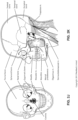
- 210000003625 skull Anatomy 0.000 description 6
- 210000004872 soft tissue Anatomy 0.000 description 6
- 230000000087 stabilizing effect Effects 0.000 description 6
- 210000003437 trachea Anatomy 0.000 description 6
- 241000083547 Columella Species 0.000 description 5
- 208000000059 Dyspnea Diseases 0.000 description 5
- 206010013975 Dyspnoeas Diseases 0.000 description 5
- 206010067775 Upper airway obstruction Diseases 0.000 description 5
- 230000008901 benefit Effects 0.000 description 5
- 210000003123 bronchiole Anatomy 0.000 description 5
- 210000001508 eye Anatomy 0.000 description 5
- 210000000867 larynx Anatomy 0.000 description 5
- 239000012780 transparent material Substances 0.000 description 5
- 208000030984 MIRAGE syndrome Diseases 0.000 description 4
- 210000000621 bronchi Anatomy 0.000 description 4
- 238000006073 displacement reaction Methods 0.000 description 4
- 239000002355 dual-layer Substances 0.000 description 4
- 210000003414 extremity Anatomy 0.000 description 4
- 239000004744 fabric Substances 0.000 description 4
- 210000002454 frontal bone Anatomy 0.000 description 4
- 208000000122 hyperventilation Diseases 0.000 description 4
- 230000003340 mental effect Effects 0.000 description 4
- 210000002184 nasal cartilage Anatomy 0.000 description 4
- 229920000515 polycarbonate Polymers 0.000 description 4
- 239000004417 polycarbonate Substances 0.000 description 4
- 230000002265 prevention Effects 0.000 description 4
- TVLSRXXIMLFWEO-UHFFFAOYSA-N prochloraz Chemical compound C1=CN=CN1C(=O)N(CCC)CCOC1=C(Cl)C=C(Cl)C=C1Cl TVLSRXXIMLFWEO-UHFFFAOYSA-N 0.000 description 4
- 230000004044 response Effects 0.000 description 4
- 239000002356 single layer Substances 0.000 description 4
- 208000024891 symptom Diseases 0.000 description 4
- 210000002105 tongue Anatomy 0.000 description 4
- 206010003497 Asphyxia Diseases 0.000 description 3
- 206010019233 Headaches Diseases 0.000 description 3
- 230000009471 action Effects 0.000 description 3
- 239000001569 carbon dioxide Substances 0.000 description 3
- 230000006735 deficit Effects 0.000 description 3
- 230000009977 dual effect Effects 0.000 description 3
- 229920001971 elastomer Polymers 0.000 description 3
- 231100000869 headache Toxicity 0.000 description 3
- 230000036541 health Effects 0.000 description 3
- 210000003026 hypopharynx Anatomy 0.000 description 3
- 239000007788 liquid Substances 0.000 description 3
- 230000014759 maintenance of location Effects 0.000 description 3
- 230000013011 mating Effects 0.000 description 3
- 239000000203 mixture Substances 0.000 description 3
- 238000012544 monitoring process Methods 0.000 description 3
- 210000000492 nasalseptum Anatomy 0.000 description 3
- 210000001989 nasopharynx Anatomy 0.000 description 3
- 230000036961 partial effect Effects 0.000 description 3
- 230000000750 progressive effect Effects 0.000 description 3
- 230000003252 repetitive effect Effects 0.000 description 3
- 210000001584 soft palate Anatomy 0.000 description 3
- 230000002269 spontaneous effect Effects 0.000 description 3
- 239000003351 stiffener Substances 0.000 description 3
- 210000000115 thoracic cavity Anatomy 0.000 description 3
- 210000000779 thoracic wall Anatomy 0.000 description 3
- 230000001960 triggered effect Effects 0.000 description 3
- 230000003519 ventilatory effect Effects 0.000 description 3
- 230000000007 visual effect Effects 0.000 description 3
- 210000001260 vocal cord Anatomy 0.000 description 3
- 208000007590 Disorders of Excessive Somnolence Diseases 0.000 description 2
- 206010013801 Duchenne Muscular Dystrophy Diseases 0.000 description 2
- 208000008589 Obesity Diseases 0.000 description 2
- -1 Polyethylene Polymers 0.000 description 2
- 206010041349 Somnolence Diseases 0.000 description 2
- 210000000577 adipose tissue Anatomy 0.000 description 2
- 239000004411 aluminium Substances 0.000 description 2
- 229910052782 aluminium Inorganic materials 0.000 description 2
- XAGFODPZIPBFFR-UHFFFAOYSA-N aluminium Chemical compound [Al] XAGFODPZIPBFFR-UHFFFAOYSA-N 0.000 description 2
- 206010002026 amyotrophic lateral sclerosis Diseases 0.000 description 2
- 230000037007 arousal Effects 0.000 description 2
- IISBACLAFKSPIT-UHFFFAOYSA-N bisphenol A Chemical compound C=1C=C(O)C=CC=1C(C)(C)C1=CC=C(O)C=C1 IISBACLAFKSPIT-UHFFFAOYSA-N 0.000 description 2
- 239000008280 blood Substances 0.000 description 2
- 210000004369 blood Anatomy 0.000 description 2
- 210000000038 chest Anatomy 0.000 description 2
- 230000001684 chronic effect Effects 0.000 description 2
- 238000004140 cleaning Methods 0.000 description 2
- 230000000295 complement effect Effects 0.000 description 2
- 239000004020 conductor Substances 0.000 description 2
- 238000013523 data management Methods 0.000 description 2
- 230000001419 dependent effect Effects 0.000 description 2
- 238000001514 detection method Methods 0.000 description 2
- 238000001035 drying Methods 0.000 description 2
- 239000000806 elastomer Substances 0.000 description 2
- 210000002532 foramen magnum Anatomy 0.000 description 2
- 230000014509 gene expression Effects 0.000 description 2
- 210000002216 heart Anatomy 0.000 description 2
- 238000007373 indentation Methods 0.000 description 2
- 230000000977 initiatory effect Effects 0.000 description 2
- 210000001847 jaw Anatomy 0.000 description 2
- 230000000670 limiting effect Effects 0.000 description 2
- 230000007935 neutral effect Effects 0.000 description 2
- 235000020824 obesity Nutrition 0.000 description 2
- 210000000103 occipital bone Anatomy 0.000 description 2
- 210000003300 oropharynx Anatomy 0.000 description 2
- 238000006213 oxygenation reaction Methods 0.000 description 2
- 210000003455 parietal bone Anatomy 0.000 description 2
- 230000007170 pathology Effects 0.000 description 2
- 229920002635 polyurethane Polymers 0.000 description 2
- 239000004814 polyurethane Substances 0.000 description 2
- 208000037821 progressive disease Diseases 0.000 description 2
- 238000005096 rolling process Methods 0.000 description 2
- 239000000126 substance Substances 0.000 description 2
- 230000009182 swimming Effects 0.000 description 2
- 210000003582 temporal bone Anatomy 0.000 description 2
- 210000001738 temporomandibular joint Anatomy 0.000 description 2
- 238000010998 test method Methods 0.000 description 2
- 238000012360 testing method Methods 0.000 description 2
- 229920001169 thermoplastic Polymers 0.000 description 2
- 210000001519 tissue Anatomy 0.000 description 2
- 238000012546 transfer Methods 0.000 description 2
- 210000001944 turbinate Anatomy 0.000 description 2
- 238000011144 upstream manufacturing Methods 0.000 description 2
- ORILYTVJVMAKLC-UHFFFAOYSA-N Adamantane Natural products C1C(C2)CC3CC1CC2C3 ORILYTVJVMAKLC-UHFFFAOYSA-N 0.000 description 1
- 206010006458 Bronchitis chronic Diseases 0.000 description 1
- BVKZGUZCCUSVTD-UHFFFAOYSA-L Carbonate Chemical compound [O-]C([O-])=O BVKZGUZCCUSVTD-UHFFFAOYSA-L 0.000 description 1
- 208000024172 Cardiovascular disease Diseases 0.000 description 1
- 208000003417 Central Sleep Apnea Diseases 0.000 description 1
- 206010011224 Cough Diseases 0.000 description 1
- 208000019505 Deglutition disease Diseases 0.000 description 1
- 206010014561 Emphysema Diseases 0.000 description 1
- 241000282412 Homo Species 0.000 description 1
- 206010020591 Hypercapnia Diseases 0.000 description 1
- 206010021133 Hypoventilation Diseases 0.000 description 1
- 206010021143 Hypoxia Diseases 0.000 description 1
- 206010023506 Kyphoscoliosis Diseases 0.000 description 1
- 206010024971 Lower respiratory tract infections Diseases 0.000 description 1
- 208000019693 Lung disease Diseases 0.000 description 1
- 241000121185 Monodon monoceros Species 0.000 description 1
- 206010027940 Mood altered Diseases 0.000 description 1
- 208000001705 Mouth breathing Diseases 0.000 description 1
- 241000208125 Nicotiana Species 0.000 description 1
- 235000002637 Nicotiana tabacum Nutrition 0.000 description 1
- 206010073310 Occupational exposures Diseases 0.000 description 1
- 206010030124 Oedema peripheral Diseases 0.000 description 1
- 206010031123 Orthopnoea Diseases 0.000 description 1
- 206010033307 Overweight Diseases 0.000 description 1
- 239000004698 Polyethylene Substances 0.000 description 1
- 239000004743 Polypropylene Substances 0.000 description 1
- 206010062519 Poor quality sleep Diseases 0.000 description 1
- 206010036790 Productive cough Diseases 0.000 description 1
- 206010070833 Respiratory muscle weakness Diseases 0.000 description 1
- 241001016288 Sesamoides Species 0.000 description 1
- 208000032140 Sleepiness Diseases 0.000 description 1
- 206010041235 Snoring Diseases 0.000 description 1
- 229910000831 Steel Inorganic materials 0.000 description 1
- 241000287181 Sturnus vulgaris Species 0.000 description 1
- 241000746998 Tragus Species 0.000 description 1
- 229920004482 WACKER® Polymers 0.000 description 1
- 208000027418 Wounds and injury Diseases 0.000 description 1
- 210000000683 abdominal cavity Anatomy 0.000 description 1
- 230000002159 abnormal effect Effects 0.000 description 1
- 239000006096 absorbing agent Substances 0.000 description 1
- 230000005534 acoustic noise Effects 0.000 description 1
- 230000003044 adaptive effect Effects 0.000 description 1
- 238000003915 air pollution Methods 0.000 description 1
- 229940124326 anaesthetic agent Drugs 0.000 description 1
- 230000003444 anaesthetic effect Effects 0.000 description 1
- 230000000844 anti-bacterial effect Effects 0.000 description 1
- 230000004596 appetite loss Effects 0.000 description 1
- 230000000712 assembly Effects 0.000 description 1
- 238000000429 assembly Methods 0.000 description 1
- 230000006399 behavior Effects 0.000 description 1
- 230000009286 beneficial effect Effects 0.000 description 1
- 239000000560 biocompatible material Substances 0.000 description 1
- 229940106691 bisphenol a Drugs 0.000 description 1
- 230000006931 brain damage Effects 0.000 description 1
- 231100000874 brain damage Toxicity 0.000 description 1
- 208000029028 brain injury Diseases 0.000 description 1
- 206010006451 bronchitis Diseases 0.000 description 1
- 210000005252 bulbus oculi Anatomy 0.000 description 1
- 230000002612 cardiopulmonary effect Effects 0.000 description 1
- 208000007451 chronic bronchitis Diseases 0.000 description 1
- 208000013116 chronic cough Diseases 0.000 description 1
- 239000002131 composite material Substances 0.000 description 1
- 230000008878 coupling Effects 0.000 description 1
- 238000010168 coupling process Methods 0.000 description 1
- 238000005859 coupling reaction Methods 0.000 description 1
- 230000006378 damage Effects 0.000 description 1
- 230000003247 decreasing effect Effects 0.000 description 1
- 230000007547 defect Effects 0.000 description 1
- 230000000994 depressogenic effect Effects 0.000 description 1
- 201000010099 disease Diseases 0.000 description 1
- 238000002224 dissection Methods 0.000 description 1
- 230000009189 diving Effects 0.000 description 1
- 239000013013 elastic material Substances 0.000 description 1
- 238000002565 electrocardiography Methods 0.000 description 1
- 238000000537 electroencephalography Methods 0.000 description 1
- 238000002567 electromyography Methods 0.000 description 1
- 210000002615 epidermis Anatomy 0.000 description 1
- 210000002409 epiglottis Anatomy 0.000 description 1
- 239000005038 ethylene vinyl acetate Substances 0.000 description 1
- 206010016256 fatigue Diseases 0.000 description 1
- 230000002068 genetic effect Effects 0.000 description 1
- 210000001983 hard palate Anatomy 0.000 description 1
- 201000000615 hard palate cancer Diseases 0.000 description 1
- 230000007954 hypoxia Effects 0.000 description 1
- 230000006872 improvement Effects 0.000 description 1
- 238000003780 insertion Methods 0.000 description 1
- 230000037431 insertion Effects 0.000 description 1
- 239000004973 liquid crystal related substance Substances 0.000 description 1
- 230000007774 longterm Effects 0.000 description 1
- 235000021266 loss of appetite Nutrition 0.000 description 1
- 208000019017 loss of appetite Diseases 0.000 description 1
- 210000001699 lower leg Anatomy 0.000 description 1
- 238000007726 management method Methods 0.000 description 1
- 208000023463 mandibuloacral dysplasia Diseases 0.000 description 1
- 238000005259 measurement Methods 0.000 description 1
- 230000010534 mechanism of action Effects 0.000 description 1
- 229910052751 metal Inorganic materials 0.000 description 1
- 239000002184 metal Substances 0.000 description 1
- 238000000120 microwave digestion Methods 0.000 description 1
- 238000012986 modification Methods 0.000 description 1
- 230000004048 modification Effects 0.000 description 1
- 230000007510 mood change Effects 0.000 description 1
- 208000001022 morbid obesity Diseases 0.000 description 1
- 238000000465 moulding Methods 0.000 description 1
- 230000003387 muscular Effects 0.000 description 1
- 201000006938 muscular dystrophy Diseases 0.000 description 1
- 230000003274 myotonic effect Effects 0.000 description 1
- 210000002850 nasal mucosa Anatomy 0.000 description 1
- 210000005036 nerve Anatomy 0.000 description 1
- 230000000414 obstructive effect Effects 0.000 description 1
- 231100000675 occupational exposure Toxicity 0.000 description 1
- 210000000056 organ Anatomy 0.000 description 1
- 208000012144 orthopnea Diseases 0.000 description 1
- 210000003254 palate Anatomy 0.000 description 1
- 230000001936 parietal effect Effects 0.000 description 1
- 230000002093 peripheral effect Effects 0.000 description 1
- 230000035699 permeability Effects 0.000 description 1
- 230000000704 physical effect Effects 0.000 description 1
- 239000004033 plastic Substances 0.000 description 1
- 229920003023 plastic Polymers 0.000 description 1
- 229920000573 polyethylene Polymers 0.000 description 1
- 229920001155 polypropylene Polymers 0.000 description 1
- 230000003334 potential effect Effects 0.000 description 1
- 239000012858 resilient material Substances 0.000 description 1
- 210000003019 respiratory muscle Anatomy 0.000 description 1
- 230000036412 respiratory physiology Effects 0.000 description 1
- 230000000284 resting effect Effects 0.000 description 1
- 230000002441 reversible effect Effects 0.000 description 1
- 230000001020 rhythmical effect Effects 0.000 description 1
- 239000005060 rubber Substances 0.000 description 1
- 206010039722 scoliosis Diseases 0.000 description 1
- 230000035945 sensitivity Effects 0.000 description 1
- 230000035939 shock Effects 0.000 description 1
- 208000013220 shortness of breath Diseases 0.000 description 1
- 229920000260 silastic Polymers 0.000 description 1
- 201000002859 sleep apnea Diseases 0.000 description 1
- 230000003860 sleep quality Effects 0.000 description 1
- 238000010321 sleep therapy Methods 0.000 description 1
- 230000037321 sleepiness Effects 0.000 description 1
- 230000000391 smoking effect Effects 0.000 description 1
- 208000024794 sputum Diseases 0.000 description 1
- 210000003802 sputum Anatomy 0.000 description 1
- 239000010959 steel Substances 0.000 description 1
- 230000000153 supplemental effect Effects 0.000 description 1
- 230000009747 swallowing Effects 0.000 description 1
- 210000004243 sweat Anatomy 0.000 description 1
- 230000002889 sympathetic effect Effects 0.000 description 1
- 208000011580 syndromic disease Diseases 0.000 description 1
- 229920003051 synthetic elastomer Polymers 0.000 description 1
- 239000005061 synthetic rubber Substances 0.000 description 1
- 230000002123 temporal effect Effects 0.000 description 1
- 229920002725 thermoplastic elastomer Polymers 0.000 description 1
- 239000004416 thermosoftening plastic Substances 0.000 description 1
- 238000004448 titration Methods 0.000 description 1
- 238000012549 training Methods 0.000 description 1
- 230000002747 voluntary effect Effects 0.000 description 1
- 238000004018 waxing Methods 0.000 description 1
Images


Classifications
-
- A—HUMAN NECESSITIES
- A61—MEDICAL OR VETERINARY SCIENCE; HYGIENE
- A61M—DEVICES FOR INTRODUCING MEDIA INTO, OR ONTO, THE BODY; DEVICES FOR TRANSDUCING BODY MEDIA OR FOR TAKING MEDIA FROM THE BODY; DEVICES FOR PRODUCING OR ENDING SLEEP OR STUPOR
- A61M16/00—Devices for influencing the respiratory system of patients by gas treatment, e.g. mouth-to-mouth respiration; Tracheal tubes
- A61M16/06—Respiratory or anaesthetic masks
- A61M16/0605—Means for improving the adaptation of the mask to the patient
- A61M16/0616—Means for improving the adaptation of the mask to the patient with face sealing means comprising a flap or membrane projecting inwards, such that sealing increases with increasing inhalation gas pressure
- A61M16/0622—Means for improving the adaptation of the mask to the patient with face sealing means comprising a flap or membrane projecting inwards, such that sealing increases with increasing inhalation gas pressure having an underlying cushion
-
- A—HUMAN NECESSITIES
- A61—MEDICAL OR VETERINARY SCIENCE; HYGIENE
- A61M—DEVICES FOR INTRODUCING MEDIA INTO, OR ONTO, THE BODY; DEVICES FOR TRANSDUCING BODY MEDIA OR FOR TAKING MEDIA FROM THE BODY; DEVICES FOR PRODUCING OR ENDING SLEEP OR STUPOR
- A61M16/00—Devices for influencing the respiratory system of patients by gas treatment, e.g. mouth-to-mouth respiration; Tracheal tubes
- A61M16/06—Respiratory or anaesthetic masks
- A61M16/0605—Means for improving the adaptation of the mask to the patient
-
- A—HUMAN NECESSITIES
- A61—MEDICAL OR VETERINARY SCIENCE; HYGIENE
- A61M—DEVICES FOR INTRODUCING MEDIA INTO, OR ONTO, THE BODY; DEVICES FOR TRANSDUCING BODY MEDIA OR FOR TAKING MEDIA FROM THE BODY; DEVICES FOR PRODUCING OR ENDING SLEEP OR STUPOR
- A61M16/00—Devices for influencing the respiratory system of patients by gas treatment, e.g. mouth-to-mouth respiration; Tracheal tubes
- A61M16/0057—Pumps therefor
- A61M16/0066—Blowers or centrifugal pumps
-
- A—HUMAN NECESSITIES
- A61—MEDICAL OR VETERINARY SCIENCE; HYGIENE
- A61M—DEVICES FOR INTRODUCING MEDIA INTO, OR ONTO, THE BODY; DEVICES FOR TRANSDUCING BODY MEDIA OR FOR TAKING MEDIA FROM THE BODY; DEVICES FOR PRODUCING OR ENDING SLEEP OR STUPOR
- A61M16/00—Devices for influencing the respiratory system of patients by gas treatment, e.g. mouth-to-mouth respiration; Tracheal tubes
- A61M16/06—Respiratory or anaesthetic masks
- A61M16/0605—Means for improving the adaptation of the mask to the patient
- A61M16/0611—Means for improving the adaptation of the mask to the patient with a gusset portion
-
- A—HUMAN NECESSITIES
- A61—MEDICAL OR VETERINARY SCIENCE; HYGIENE
- A61M—DEVICES FOR INTRODUCING MEDIA INTO, OR ONTO, THE BODY; DEVICES FOR TRANSDUCING BODY MEDIA OR FOR TAKING MEDIA FROM THE BODY; DEVICES FOR PRODUCING OR ENDING SLEEP OR STUPOR
- A61M16/00—Devices for influencing the respiratory system of patients by gas treatment, e.g. mouth-to-mouth respiration; Tracheal tubes
- A61M16/06—Respiratory or anaesthetic masks
- A61M16/0605—Means for improving the adaptation of the mask to the patient
- A61M16/0616—Means for improving the adaptation of the mask to the patient with face sealing means comprising a flap or membrane projecting inwards, such that sealing increases with increasing inhalation gas pressure
-
- A—HUMAN NECESSITIES
- A61—MEDICAL OR VETERINARY SCIENCE; HYGIENE
- A61M—DEVICES FOR INTRODUCING MEDIA INTO, OR ONTO, THE BODY; DEVICES FOR TRANSDUCING BODY MEDIA OR FOR TAKING MEDIA FROM THE BODY; DEVICES FOR PRODUCING OR ENDING SLEEP OR STUPOR
- A61M16/00—Devices for influencing the respiratory system of patients by gas treatment, e.g. mouth-to-mouth respiration; Tracheal tubes
- A61M16/06—Respiratory or anaesthetic masks
- A61M16/0605—Means for improving the adaptation of the mask to the patient
- A61M16/0633—Means for improving the adaptation of the mask to the patient with forehead support
-
- A—HUMAN NECESSITIES
- A61—MEDICAL OR VETERINARY SCIENCE; HYGIENE
- A61M—DEVICES FOR INTRODUCING MEDIA INTO, OR ONTO, THE BODY; DEVICES FOR TRANSDUCING BODY MEDIA OR FOR TAKING MEDIA FROM THE BODY; DEVICES FOR PRODUCING OR ENDING SLEEP OR STUPOR
- A61M16/00—Devices for influencing the respiratory system of patients by gas treatment, e.g. mouth-to-mouth respiration; Tracheal tubes
- A61M16/06—Respiratory or anaesthetic masks
- A61M16/0666—Nasal cannulas or tubing
-
- A—HUMAN NECESSITIES
- A61—MEDICAL OR VETERINARY SCIENCE; HYGIENE
- A61M—DEVICES FOR INTRODUCING MEDIA INTO, OR ONTO, THE BODY; DEVICES FOR TRANSDUCING BODY MEDIA OR FOR TAKING MEDIA FROM THE BODY; DEVICES FOR PRODUCING OR ENDING SLEEP OR STUPOR
- A61M16/00—Devices for influencing the respiratory system of patients by gas treatment, e.g. mouth-to-mouth respiration; Tracheal tubes
- A61M16/06—Respiratory or anaesthetic masks
- A61M16/0683—Holding devices therefor
-
- A—HUMAN NECESSITIES
- A61—MEDICAL OR VETERINARY SCIENCE; HYGIENE
- A61M—DEVICES FOR INTRODUCING MEDIA INTO, OR ONTO, THE BODY; DEVICES FOR TRANSDUCING BODY MEDIA OR FOR TAKING MEDIA FROM THE BODY; DEVICES FOR PRODUCING OR ENDING SLEEP OR STUPOR
- A61M16/00—Devices for influencing the respiratory system of patients by gas treatment, e.g. mouth-to-mouth respiration; Tracheal tubes
- A61M16/08—Bellows; Connecting tubes ; Water traps; Patient circuits
- A61M16/0816—Joints or connectors
- A61M16/0825—Joints or connectors with ball-sockets
-
- A—HUMAN NECESSITIES
- A61—MEDICAL OR VETERINARY SCIENCE; HYGIENE
- A61M—DEVICES FOR INTRODUCING MEDIA INTO, OR ONTO, THE BODY; DEVICES FOR TRANSDUCING BODY MEDIA OR FOR TAKING MEDIA FROM THE BODY; DEVICES FOR PRODUCING OR ENDING SLEEP OR STUPOR
- A61M16/00—Devices for influencing the respiratory system of patients by gas treatment, e.g. mouth-to-mouth respiration; Tracheal tubes
- A61M16/0057—Pumps therefor
- A61M16/0066—Blowers or centrifugal pumps
- A61M16/0069—Blowers or centrifugal pumps the speed thereof being controlled by respiratory parameters, e.g. by inhalation
-
- A—HUMAN NECESSITIES
- A61—MEDICAL OR VETERINARY SCIENCE; HYGIENE
- A61M—DEVICES FOR INTRODUCING MEDIA INTO, OR ONTO, THE BODY; DEVICES FOR TRANSDUCING BODY MEDIA OR FOR TAKING MEDIA FROM THE BODY; DEVICES FOR PRODUCING OR ENDING SLEEP OR STUPOR
- A61M16/00—Devices for influencing the respiratory system of patients by gas treatment, e.g. mouth-to-mouth respiration; Tracheal tubes
- A61M16/08—Bellows; Connecting tubes ; Water traps; Patient circuits
- A61M16/0875—Connecting tubes
-
- A—HUMAN NECESSITIES
- A61—MEDICAL OR VETERINARY SCIENCE; HYGIENE
- A61M—DEVICES FOR INTRODUCING MEDIA INTO, OR ONTO, THE BODY; DEVICES FOR TRANSDUCING BODY MEDIA OR FOR TAKING MEDIA FROM THE BODY; DEVICES FOR PRODUCING OR ENDING SLEEP OR STUPOR
- A61M16/00—Devices for influencing the respiratory system of patients by gas treatment, e.g. mouth-to-mouth respiration; Tracheal tubes
- A61M16/10—Preparation of respiratory gases or vapours
- A61M16/105—Filters
- A61M16/1055—Filters bacterial
-
- A—HUMAN NECESSITIES
- A61—MEDICAL OR VETERINARY SCIENCE; HYGIENE
- A61M—DEVICES FOR INTRODUCING MEDIA INTO, OR ONTO, THE BODY; DEVICES FOR TRANSDUCING BODY MEDIA OR FOR TAKING MEDIA FROM THE BODY; DEVICES FOR PRODUCING OR ENDING SLEEP OR STUPOR
- A61M16/00—Devices for influencing the respiratory system of patients by gas treatment, e.g. mouth-to-mouth respiration; Tracheal tubes
- A61M16/10—Preparation of respiratory gases or vapours
- A61M16/105—Filters
- A61M16/106—Filters in a path
- A61M16/107—Filters in a path in the inspiratory path
-
- A—HUMAN NECESSITIES
- A61—MEDICAL OR VETERINARY SCIENCE; HYGIENE
- A61M—DEVICES FOR INTRODUCING MEDIA INTO, OR ONTO, THE BODY; DEVICES FOR TRANSDUCING BODY MEDIA OR FOR TAKING MEDIA FROM THE BODY; DEVICES FOR PRODUCING OR ENDING SLEEP OR STUPOR
- A61M16/00—Devices for influencing the respiratory system of patients by gas treatment, e.g. mouth-to-mouth respiration; Tracheal tubes
- A61M16/10—Preparation of respiratory gases or vapours
- A61M16/1075—Preparation of respiratory gases or vapours by influencing the temperature
- A61M16/109—Preparation of respiratory gases or vapours by influencing the temperature the humidifying liquid or the beneficial agent
-
- A—HUMAN NECESSITIES
- A61—MEDICAL OR VETERINARY SCIENCE; HYGIENE
- A61M—DEVICES FOR INTRODUCING MEDIA INTO, OR ONTO, THE BODY; DEVICES FOR TRANSDUCING BODY MEDIA OR FOR TAKING MEDIA FROM THE BODY; DEVICES FOR PRODUCING OR ENDING SLEEP OR STUPOR
- A61M16/00—Devices for influencing the respiratory system of patients by gas treatment, e.g. mouth-to-mouth respiration; Tracheal tubes
- A61M16/10—Preparation of respiratory gases or vapours
- A61M16/1075—Preparation of respiratory gases or vapours by influencing the temperature
- A61M16/1095—Preparation of respiratory gases or vapours by influencing the temperature in the connecting tubes
-
- A—HUMAN NECESSITIES
- A61—MEDICAL OR VETERINARY SCIENCE; HYGIENE
- A61M—DEVICES FOR INTRODUCING MEDIA INTO, OR ONTO, THE BODY; DEVICES FOR TRANSDUCING BODY MEDIA OR FOR TAKING MEDIA FROM THE BODY; DEVICES FOR PRODUCING OR ENDING SLEEP OR STUPOR
- A61M16/00—Devices for influencing the respiratory system of patients by gas treatment, e.g. mouth-to-mouth respiration; Tracheal tubes
- A61M16/10—Preparation of respiratory gases or vapours
- A61M16/14—Preparation of respiratory gases or vapours by mixing different fluids, one of them being in a liquid phase
- A61M16/16—Devices to humidify the respiration air
-
- A—HUMAN NECESSITIES
- A61—MEDICAL OR VETERINARY SCIENCE; HYGIENE
- A61M—DEVICES FOR INTRODUCING MEDIA INTO, OR ONTO, THE BODY; DEVICES FOR TRANSDUCING BODY MEDIA OR FOR TAKING MEDIA FROM THE BODY; DEVICES FOR PRODUCING OR ENDING SLEEP OR STUPOR
- A61M2202/00—Special media to be introduced, removed or treated
- A61M2202/02—Gases
- A61M2202/0225—Carbon oxides, e.g. Carbon dioxide
-
- A—HUMAN NECESSITIES
- A61—MEDICAL OR VETERINARY SCIENCE; HYGIENE
- A61M—DEVICES FOR INTRODUCING MEDIA INTO, OR ONTO, THE BODY; DEVICES FOR TRANSDUCING BODY MEDIA OR FOR TAKING MEDIA FROM THE BODY; DEVICES FOR PRODUCING OR ENDING SLEEP OR STUPOR
- A61M2205/00—General characteristics of the apparatus
- A61M2205/42—Reducing noise
-
- A—HUMAN NECESSITIES
- A61—MEDICAL OR VETERINARY SCIENCE; HYGIENE
- A61M—DEVICES FOR INTRODUCING MEDIA INTO, OR ONTO, THE BODY; DEVICES FOR TRANSDUCING BODY MEDIA OR FOR TAKING MEDIA FROM THE BODY; DEVICES FOR PRODUCING OR ENDING SLEEP OR STUPOR
- A61M2207/00—Methods of manufacture, assembly or production
-
- A—HUMAN NECESSITIES
- A61—MEDICAL OR VETERINARY SCIENCE; HYGIENE
- A61M—DEVICES FOR INTRODUCING MEDIA INTO, OR ONTO, THE BODY; DEVICES FOR TRANSDUCING BODY MEDIA OR FOR TAKING MEDIA FROM THE BODY; DEVICES FOR PRODUCING OR ENDING SLEEP OR STUPOR
- A61M2210/00—Anatomical parts of the body
- A61M2210/06—Head
- A61M2210/0606—Face
-
- A—HUMAN NECESSITIES
- A61—MEDICAL OR VETERINARY SCIENCE; HYGIENE
- A61M—DEVICES FOR INTRODUCING MEDIA INTO, OR ONTO, THE BODY; DEVICES FOR TRANSDUCING BODY MEDIA OR FOR TAKING MEDIA FROM THE BODY; DEVICES FOR PRODUCING OR ENDING SLEEP OR STUPOR
- A61M2210/00—Anatomical parts of the body
- A61M2210/06—Head
- A61M2210/0618—Nose
Definitions
- the present technology relates to one or more of the detection, diagnosis, treatment, prevention and amelioration of respiratory-related disorders.
- the present technology also relates to medical devices or apparatus, and their use.
- the invention relates to a cushion assembly, a patient interface, and a CPAP system.
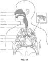
- the respiratory system of the body facilitates gas exchange.
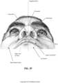
- the nose and mouth form the entrance to the airways of a patient.
- the airways include a series of branching tubes, which become narrower, shorter and more numerous as they penetrate deeper into the lung.
- the prime function of the lung is gas exchange, allowing oxygen to move from the inhaled air into the venous blood and carbon dioxide to move in the opposite direction.
- the trachea divides into right and left main bronchi, which further divide eventually into terminal bronchioles.
- the bronchi make up the conducting airways, and do not take part in gas exchange. Further divisions of the airways lead to the respiratory bronchioles, and eventually to the alveoli.
- the alveolated region of the lung is where the gas exchange takes place, and is referred to as the respiratory zone. See " Respiratory Physiology", by John B. West, Lippincott Williams & Wilkins, 9th edition published 2012 .
- a range of respiratory disorders exist. Certain disorders may be characterised by particular events, e.g. apneas, hypopneas, and hyperpneas.
- respiratory disorders include Obstructive Sleep Apnea (OSA), Cheyne-Stokes Respiration (CSR), respiratory insufficiency, Obesity Hyperventilation Syndrome (OHS), Chronic Obstructive Pulmonary Disease (COPD), Neuromuscular Disease (NMD) and Chest wall disorders.
- OSA Obstructive Sleep Apnea
- CSR Cheyne-Stokes Respiration
- OOS Obesity Hyperventilation Syndrome
- COPD Chronic Obstructive Pulmonary Disease
- NMD Neuromuscular Disease
- Chest wall disorders examples include Obstructive Sleep Apnea (OSA), Cheyne-Stokes Respiration (CSR), respiratory insufficiency, Obesity Hyperventilation Syndrome (OHS), Chronic Obstructive Pulmonary Disease (COPD), Neuromuscular Disease (NMD) and Chest wall disorders.
- Obstructive Sleep Apnea a form of Sleep Disordered Breathing (SDB), is characterized by events including occlusion or obstruction of the upper air passage during sleep. It results from a combination of an abnormally small upper airway and the normal loss of muscle tone in the region of the tongue, soft palate and posterior oropharyngeal wall during sleep.
- the condition causes the affected patient to stop breathing for periods typically of 30 to 120 seconds in duration, sometimes 200 to 300 times per night. It often causes excessive daytime somnolence, and it may cause cardiovascular disease and brain damage.
- the syndrome is a common disorder, particularly in middle aged overweight males, although a person affected may have no awareness of the problem. See US Patent No. 4,944,310 (Sullivan ).
- CSR Cheyne-Stokes Respiration
- CSR cycles rhythmic alternating periods of waxing and waning ventilation known as CSR cycles.
- CSR is characterised by repetitive de-oxygenation and re-oxygenation of the arterial blood. It is possible that CSR is harmful because of the repetitive hypoxia. In some patients CSR is associated with repetitive arousal from sleep, which causes severe sleep disruption, increased sympathetic activity, and increased afterload. See US Patent No. 6,532,959 (Berthon-Jones ).
- Respiratory failure is an umbrella term for respiratory disorders in which the lungs are unable to inspire sufficient oxygen or exhale sufficient CO 2 to meet the patient's needs. Respiratory failure may encompass some or all of the following disorders.
- a patient with respiratory insufficiency (a form of respiratory failure) may experience abnormal shortness of breath on exercise.
- Obesity Hyperventilation Syndrome is defined as the combination of severe obesity and awake chronic hypercapnia, in the absence of other known causes for hypoventilation. Symptoms include dyspnea, morning headache and excessive daytime sleepiness.
- COPD Chronic Obstructive Pulmonary Disease
- COPD encompasses any of a group of lower airway diseases that have certain characteristics in common. These include increased resistance to air movement, extended expiratory phase of respiration, and loss of the normal elasticity of the lung. Examples of COPD are emphysema and chronic bronchitis. COPD is caused by chronic tobacco smoking (primary risk factor), occupational exposures, air pollution and genetic factors. Symptoms include: dyspnea on exertion, chronic cough and sputum production.
- Neuromuscular Disease is a broad term that encompasses many diseases and ailments that impair the functioning of the muscles either directly via intrinsic muscle pathology, or indirectly via nerve pathology.
- Some NMD patients are characterised by progressive muscular impairment leading to loss of ambulation, being wheelchair-bound, swallowing difficulties, respiratory muscle weakness and, eventually, death from respiratory failure.
- Neuromuscular disorders can be divided into rapidly progressive and slowly progressive: (i) Rapidly progressive disorders: Characterised by muscle impairment that worsens over months and results in death within a few years (e.g.
- ALS Amyotrophic lateral sclerosis
- DMD Duchenne muscular dystrophy
- Variable or slowly progressive disorders Characterised by muscle impairment that worsens over years and only mildly reduces life expectancy (e.g. Limb girdle, Facioscapulohumeral and Myotonic muscular dystrophy).
- Symptoms of respiratory failure in NMD include: increasing generalised weakness, dysphagia, dyspnea on exertion and at rest, fatigue, sleepiness, morning headache, and difficulties with concentration and mood changes.
- Chest wall disorders are a group of thoracic deformities that result in inefficient coupling between the respiratory muscles and the thoracic cage.
- the disorders are usually characterised by a restrictive defect and share the potential of long term hypercapnic respiratory failure.
- Scoliosis and/or kyphoscoliosis may cause severe respiratory failure.
- Symptoms of respiratory failure include: dyspnea on exertion, peripheral oedema, orthopnea, repeated chest infections, morning headaches, fatigue, poor sleep quality and loss of appetite.
- a range of therapies have been used to treat or ameliorate such conditions. Furthermore, otherwise healthy individuals may take advantage of such therapies to prevent respiratory disorders from arising. However, these have a number of shortcomings.
- CPAP Continuous Positive Airway Pressure
- NMV Non-invasive ventilation
- IV Invasive ventilation
- Continuous Positive Airway Pressure (CPAP) therapy has been used to treat Obstructive Sleep Apnea (OSA).
- OSA Obstructive Sleep Apnea
- the mechanism of action is that continuous positive airway pressure acts as a pneumatic splint and may prevent upper airway occlusion, such as by pushing the soft palate and tongue forward and away from the posterior oropharyngeal wall.
- Treatment of OSA by CPAP therapy may be voluntary, and hence patients may elect not to comply with therapy if they find devices used to provide such therapy one or more of: uncomfortable, difficult to use, expensive and aesthetically unappealing.
- Non-invasive ventilation provides ventilatory support to a patient through the upper airways to assist the patient breathing and/or maintain adequate oxygen levels in the body by doing some or all of the work of breathing.
- the ventilatory support is provided via a non-invasive patient interface.
- NIV has been used to treat CSR and respiratory failure, in forms such as OHS, COPD, NMD and Chest Wall disorders. In some forms, the comfort and effectiveness of these therapies may be improved.
- IV Invasive ventilation
- These therapies may be provided by a treatment system or device. Such systems and devices may also be used to diagnose a condition without treating it.
- a treatment system may comprise a Respiratory Pressure Therapy Device (RPT device), an air circuit, a humidifier, a patient interface, and data management.
- RPT device Respiratory Pressure Therapy Device
- Another form of treatment system is a mandibular repositioning device.
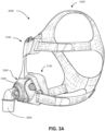
- a patient interface may be used to interface respiratory equipment to its wearer, for example by providing a flow of air to an entrance to the airways.
- the flow of air may be provided via a mask to the nose and/or mouth, a tube to the mouth or a tracheostomy tube to the trachea of a patient.
- the patient interface may form a seal, e.g., with a region of the patient's face, to facilitate the delivery of gas at a pressure at sufficient variance with ambient pressure to effect therapy, e.g., at a positive pressure of about 10 cmH 2 O relative to ambient pressure.
- the patient interface may not include a seal sufficient to facilitate delivery to the airways of a supply of gas at a positive pressure of about 10 cmH 2 O.
- Certain other mask systems may be functionally unsuitable for the present field.
- purely ornamental masks may be unable to maintain a suitable pressure.
- Mask systems used for underwater swimming or diving may be configured to guard against ingress of water from an external higher pressure, but not to maintain air internally at a higher pressure than ambient.
- Certain masks may be clinically unfavourable for the present technology e.g. if they block airflow via the nose and only allow it via the mouth.
- Certain masks may be uncomfortable or impractical for the present technology if they require a patient to insert a portion of a mask structure in their mouth to create and maintain a seal via their lips.
- Certain masks may be impractical for use while sleeping, e.g. for sleeping while lying on one's side in bed with a head on a pillow.
- the design of a patient interface presents a number of challenges.
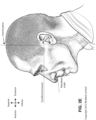
- the face has a complex three-dimensional shape.
- the size and shape of noses and heads varies considerably between individuals. Since the head includes bone, cartilage and soft tissue, different regions of the face respond differently to mechanical forces.
- the jaw or mandible may move relative to other bones of the skull. The whole head may move during the course of a period of respiratory therapy.
- masks suffer from being one or more of obtrusive, aesthetically undesirable, costly, poorly fitting, difficult to use, and uncomfortable especially when worn for long periods of time or when a patient is unfamiliar with a system. Wrongly sized masks can give rise to reduced compliance, reduced comfort and poorer patient outcomes.
- Masks designed solely for aviators, masks designed as part of personal protection equipment (e.g. filter masks), SCUBA masks, or for the administration of anaesthetics may be tolerable for their original application, but nevertheless such masks may be undesirably uncomfortable to be worn for extended periods of time, e.g., several hours. This discomfort may lead to a reduction in patient compliance with therapy. This is even more so if the mask is to be worn during sleep.
- CPAP therapy is highly effective to treat certain respiratory disorders, provided patients comply with therapy. If a mask is uncomfortable, or difficult to use a patient may not comply with therapy. Since it is often recommended that a patient regularly wash their mask, if a mask is difficult to clean (e.g., difficult to assemble or disassemble), patients may not clean their mask and this may impact on patient compliance.
- a mask for other applications may not be suitable for use in treating sleep disordered breathing
- a mask designed for use in treating sleep disordered breathing may be suitable for other applications.
- patient interfaces for delivery of CPAP during sleep form a distinct field.
- Patient interfaces may include a seal-forming portion. Since it is in direct contact with the patient's face, the shape and configuration of the seal-forming portion can have a direct impact the effectiveness and comfort of the patient interface.
- a patient interface may be partly characterised according to the design intent of where the seal-forming portion is to engage with the face in use.
- a seal-forming portion may comprise a first sub-portion to form a seal around the left naris and a second sub-portion to form a seal around the right naris.
- a seal-forming portion may comprise a single element that surrounds both nares in use. Such single element may be designed to for example overlay an upper lip region and a nasal bridge region of a face.
- a seal-forming portion may comprise an element that surrounds a mouth region in use, e.g. by forming a seal on a lower lip region of a face.
- a seal-forming portion may comprise a single element that surrounds both nares and a mouth region in use.
- These different types of patient interfaces may be known by a variety of names by their manufacturer including nasal masks, full-face masks, nasal pillows, nasal puffs and oro-nasal masks.
- a seal-forming portion that may be effective in one region of a patient's face may be inappropriate in another region, e.g. because of the different shape, structure, variability and sensitivity regions of the patient's face.
- a seal on swimming goggles that overlays a patient's forehead may not be appropriate to use on a patient's nose.
- Certain seal-forming portions may be designed for mass manufacture such that one design fit and be comfortable and effective for a wide range of different face shapes and sizes. To the extent to which there is a mismatch between the shape of the patient's face, and the seal-forming portion of the mass-manufactured patient interface, one or both must adapt in order for a seal to form.
- seal-forming portion extends around the periphery of the patient interface, and is intended to seal against the patient's face when force is applied to the patient interface with the seal-forming portion in confronting engagement with the patient's face.
- the seal-forming portion may include an air or fluid filled cushion, or a moulded or formed surface of a resilient seal element made of an elastomer such as a rubber.
- seal-forming portion incorporates a flap seal of thin material positioned about the periphery of the mask so as to provide a self-sealing action against the face of the patient when positive pressure is applied within the mask.
- flap seal of thin material positioned about the periphery of the mask so as to provide a self-sealing action against the face of the patient when positive pressure is applied within the mask.
- additional force may be required to achieve a seal, or the mask may leak.
- shape of the seal-forming portion does not match that of the patient, it may crease or buckle in use, giving rise to leaks.
- seal-forming portion may comprise a friction-fit element, e.g. for insertion into a naris, however some patients find these uncomfortable.
- seal-forming portion may use adhesive to achieve a seal. Some patients may find it inconvenient to constantly apply and remove an adhesive to their face.
- nasal pillow is found in the Adam Circuit manufactured by Puritan Bennett.
- Another nasal pillow, or nasal puff is the subject of US Patent 4,782,832 (Trimble et al .), assigned to Puritan-Bennett Corporation.
- ResMed Limited has manufactured the following products that incorporate nasal pillows: SWIFT TM nasal pillows mask, SWIFT TM II nasal pillows mask, SWIFT TM LT nasal pillows mask, SWIFT TM FX nasal pillows mask and MIRAGE LIBERTY TM full-face mask.
- a seal-forming portion of a patient interface used for positive air pressure therapy is subject to the corresponding force of the air pressure to disrupt a seal.
- a variety of techniques have been used to position the seal-forming portion, and to maintain it in sealing relation with the appropriate portion of the face.
- Another technique is the use of one or more straps and/or stabilising harnesses. Many such harnesses suffer from being one or more of ill-fitting, bulky, uncomfortable and awkward to use.
- a respiratory pressure therapy (RPT) device may be used to deliver one or more of a number of therapies described above, such as by generating a flow of air for delivery to an entrance to the airways.
- the flow of air may be pressurised.
- RPT devices include a CPAP device and a ventilator.
- Air pressure generators are known in a range of applications, e.g. industrial-scale ventilation systems. However, air pressure generators for medical applications have particular requirements not fulfilled by more generalised air pressure generators, such as the reliability, size and weight requirements of medical devices. In addition, even devices designed for medical treatment may suffer from shortcomings, pertaining to one or more of: comfort, noise, ease of use, efficacy, size, weight, manufacturability, cost, and reliability.
- RPT device used for treating sleep disordered breathing is the S9 Sleep Therapy System, manufactured by ResMed Limited.
- RPT device is a ventilator.
- Ventilators such as the ResMed Stellar TM Series of Adult and Paediatric Ventilators may provide support for invasive and non-invasive non-dependent ventilation for a range of patients for treating a number of conditions such as but not limited to NMD, OHS and COPD.
- the ResMed Elisee TM 150 ventilator and ResMed VS III TM ventilator may provide support for invasive and non-invasive dependent ventilation suitable for adult or paediatric patients for treating a number of conditions. These ventilators provide volumetric and barometric ventilation modes with a single or double limb circuit.
- RPT devices typically comprise a pressure generator, such as a motor-driven blower or a compressed gas reservoir, and are configured to supply a flow of air to the airway of a patient. In some cases, the flow of air may be supplied to the airway of the patient at positive pressure.
- the outlet of the RPT device is connected via an air circuit to a patient interface such as those described above.
- the designer of a device may be presented with an infinite number of choices to make. Design criteria often conflict, meaning that certain design choices are far from routine or inevitable. Furthermore, the comfort and efficacy of certain aspects may be highly sensitive to small, subtle changes in one or more parameters.
- a range of artificial humidification devices and systems are known, however they may not fulfil the specialised requirements of a medical humidifier.
- Medical humidifiers are used to increase humidity and/or temperature of the flow of air in relation to ambient air when required, typically where the patient may be asleep or resting (e.g. at a hospital).
- a medical humidifier for bedside placement may be small.
- a medical humidifier may be configured to only humidify and/or heat the flow of air delivered to the patient without humidifying and/or heating the patient's surroundings.
- Room-based systems e.g. a sauna, an air conditioner, or an evaporative cooler
- medical humidifiers may have more stringent safety constraints than industrial humidifiers
- a compliance rule for CPAP therapy is that a patient, in order to be deemed compliant, is required to use the RPT device for at least four hours a night for at least 21 of 30 consecutive days.
- a provider of the RPT device such as a health care provider, may manually obtain data describing the patient's therapy using the RPT device, calculate the usage over a predetermined time period, and compare with the compliance rule. Once the health care provider has determined that the patient has used their RPT device according to the compliance rule, the health care provider may notify a third party that the patient is compliant.
- a mandibular repositioning device (MRD) or mandibular advancement device (MAD) is one of the treatment options for sleep apnea and snoring. It is an adjustable oral appliance available from a dentist or other supplier that holds the lower jaw (mandible) in a forward position during sleep.
- the MRD is a removable device that a patient inserts into their mouth prior to going to sleep and removes following sleep. Thus, the MRD is not designed to be worn all of the time.
- the MRD may be custom made or produced in a standard form and includes a bite impression portion designed to allow fitting to a patient's teeth. This mechanical protrusion of the lower jaw expands the space behind the tongue, puts tension on the pharyngeal walls to reduce collapse of the airway and diminishes palate vibration.
- a mandibular advancement device may comprise an upper splint that is intended to engage with or fit over teeth on the upper jaw or maxilla and a lower splint that is intended to engage with or fit over teeth on the upper jaw or mandible.
- the upper and lower splints are connected together laterally via a pair of connecting rods.
- the pair of connecting rods are fixed symmetrically on the upper splint and on the lower splint.
- the length of the connecting rods is selected such that when the MRD is placed in a patient's mouth the mandible is held in an advanced position.
- the length of the connecting rods may be adjusted to change the level of protrusion of the mandible.
- a dentist may determine a level of protrusion for the mandible that will determine the length of the connecting rods.
- MRDs are structured to push the mandible forward relative to the maxilla while other MADs, such as the ResMed Narval CC TM MRD are designed to retain the mandible in a forward position.
- This device also reduces or minimises dental and temporo-mandibular joint (TMJ) side effects. Thus, it is configured to minimises or prevent any movement of one or more of the teeth.
- Some forms of treatment systems may include a vent to allow the washout of exhaled carbon dioxide.
- the vent may allow a flow of gas from an interior space of a patient interface, e.g., the plenum chamber, to an exterior of the patient interface, e.g., to ambient.
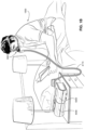
- the vent may comprise an orifice and gas may flow through the orifice in use of the mask. Many such vents are noisy. Others may become blocked in use and thus provide insufficient washout. Some vents may be disruptive of the sleep of a bed partner 1100 of the patient 1000, e.g. through noise or focussed airflow.
- ResMed Limited has developed a number of improved mask vent technologies. See International Patent Application Publication No. WO 1998/034,665 ; International Patent Application Publication No. WO 2000/078,381 ; US Patent No. 6,581,594 ; US Patent Application Publication No. US 2009/0050156 ; US Patent Application Publication No. 2009/0044808 .
- PSG Polysomnography
- EEG electroencephalography
- ECG electrocardiography
- EOG electrooculograpy
- EMG electromyography
- PSG for sleep disordered breathing has involved two nights of observation of a patient in a clinic, one night of pure diagnosis and a second night of titration of treatment parameters by a clinician. PSG is therefore expensive and inconvenient. In particular it is unsuitable for home sleep testing.
- Clinical experts may be able to diagnose or monitor patients adequately based on visual observation of PSG signals. However, there are circumstances where a clinical expert may not be available, or a clinical expert may not be affordable. Different clinical experts may disagree on a patient's condition. In addition, a given clinical expert may apply a different standard at different times.
- US 2014/0174446 A1 relates to an interface assembly comprises a nasal mask that includes a seal having a rolling portion, wherein the rolling portion of the seal rolls over a portion of a clip that secures the seal to a frame. Furthermore, it is said that the frame has a ball and socket connection to a connector and that the connector comprises an elbow having integrally formed exhaust holes and a swivel.
- the present technology is directed towards providing medical devices used in the diagnosis, amelioration, treatment, or prevention of respiratory disorders having one or more of improved comfort, cost, efficacy, ease of use and manufacturability.
- a first aspect of the present technology relates to apparatus used in the diagnosis, amelioration, treatment or prevention of a respiratory disorder.
- Another aspect of the present technology relates to methods used in the diagnosis, amelioration, treatment or prevention of a respiratory disorder.
- An aspect of certain forms of the present technology is to provide methods and/or apparatus that improve the compliance of patients with respiratory therapy.
- One aspect of the present technology is directed to a patient interface that comprises: a plenum chamber pressurisable to a therapeutic pressure of at least 6cmH2O above ambient air pressure, said plenum chamber including a plenum chamber inlet port, said plenum chamber inlet port being sized and structured to receive a flow of air at the therapeutic pressure for breathing by a patient; a sealing structure constructed and arranged to have a shape to form a seal with a region of the patient's face surrounding an entrance to the patient's airways such that the flow of air at said therapeutic pressure is delivered to at least an entrance to the patient's nares, said seal being formed to prevent air exiting from the plenum chamber between the sealing structure and said region of the patient's face, the sealing structure structured and arranged to maintain said therapeutic pressure in the plenum chamber throughout the patient's respiratory cycle in use; a positioning and stabilising structure to maintain the sealing structure in a therapeutically effective position on the patient's head while the patient is lying in a side sleeping position and while the patient
- the sealing structure may comprise the second interior surface region, the second interior surface region being spaced from the first interior surface region
- the plenum chamber may comprise the second interior surface region, the second interior surface region being spaced from the first interior surface region
- the tie and the sealing structure may comprise a unitary structure formed from a homogeneous material
- the homogeneous material may be silicone rubber
- the silicone rubber may be liquid silicone rubber or compression molded silicone rubber
- the sealing structure may comprises a sealing flap at an edge region, the sealing flap being shaped and positioned to seal at least against a side of the patient's nose in use, and the sealing flap being thinner than adjacent regions of the sealing structure
- the first interior surface region may be adjacent to the sealing flap such that the tie is spaced inwardly from the sealing flap
- the tie may extend contiguously from the sealing structure at an edge region such that the tie forms an extension of the sealing surface
- the tie may comprise an inner surface and the sealing structure may comprise
- Another aspect of the present technology is directed to an assembly for a patient interface that comprises: a plenum chamber pressurisable to a therapeutic pressure of at least 6cmH2O above ambient air pressure, said plenum chamber including a plenum chamber inlet port, said plenum chamber inlet port being sized and structured to receive a flow of air at the therapeutic pressure for breathing by a patient; and a sealing structure constructed and arranged to have a shape to form a seal with a region of the patient's face surrounding an entrance to the patient's airways such that the flow of air at said therapeutic pressure is delivered to at least an entrance to the patient's nares, said seal being formed to prevent air exiting from the plenum chamber between the sealing structure and said region of the patient's face, the sealing structure structured and arranged to maintain said therapeutic pressure in the plenum chamber throughout the patient's respiratory cycle in use; wherein the sealing structure comprises a sealing surface that forms the seal against the patient's face in use, wherein the sealing structure comprises a connecting portion that extends
- the sealing structure may comprise the second interior surface region, the second interior surface region being spaced from the first interior surface region
- the plenum chamber may comprise the second interior surface region, the second interior surface region being spaced from the first interior surface region
- the connecting portion and the sealing structure may comprise a unitary structure formed from a homogeneous material,
- the homogeneous material may be silicone rubber,
- the silicone rubber may liquid silicone rubber or compression molded silicone rubber,
- the sealing structure may comprise a sealing flap at an edge region, the sealing flap being shaped and positioned to seal at least against a side of the patient's nose in use, and the sealing flap being thinner than adjacent regions of the sealing structure
- the first interior surface region may be adjacent to the sealing flap such that the connecting portion is spaced inwardly from the sealing flap
- the connecting portion may extend contiguously from the sealing structure at an edge region such that the connecting portion forms an extension of the sealing surface
- the connecting portion may comprise an inner surface and the
- the sealing structure includes a flap or membrane that extends inward towards the user's airways and includes an attachment structure that prevents an inner boundary of the flap or membrane from being blown outwards (e.g., folded backwards upon itself) due to internal pressurization.
- the attachment structure may comprise: one or more ribs/ties/connecting portions/connecting structures, a flap that extends from the membrane and folds inwards and attaches to another structure to form a tube or loop, or a tube underlying and attached to the membrane.
- Another aspect of one form of the present technology is a sealing structure for a patient interface for sealed delivery of a flow of air at a continuously positive pressure with respect to ambient air pressure to an entrance to the patient's airways including at least entrance of a patient's nares.
- the patient interface is configured to maintain a therapy pressure in a range of about 3 cmH2O to about 40 cmH2O above ambient air pressure in use, throughout the patient's respiratory cycle, while the patient is sleeping, to ameliorate sleep disordered breathing.
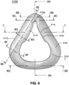
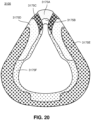
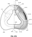
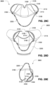
- the sealing structure comprises: a sealing surface configured to form a seal around a periphery of the entrance to the patient's airways, and a loop that folds the sealing structure inwards of an outer perimeter of the sealing structure to form a substantially tube-shaped structure so that the loop is continuous, the loop comprising a portion of the sealing surface.
- the sealing structure further comprising a sealing flap protruding towards an inner perimeter of the sealing structure, (b) the sealing flap is configured to form a seal against the sides of the nose above the nasal bones of the patient, (c) the sealing flap is configured to avoid sealing against the alar, (d) the portion of the sealing surface has increased flexibility relative to a remaining portion of the loop the portion of the sealing surface comprises a thinner wall section than a remaining portion of the loop, (e) the portion of the sealing surface comprises a thicker wall section than a remaining portion of the loop, (f) the loop is located to contact the side wall of the nose including the alar, (g) the loop provides a continuous surface configured to maintain contact with the sides of the nose, above the nasal bones of the patient, (h) the loop comprises at least one closed end, (i) the loop folds the sealing structure inwards to form a connection point on an inner surface of the sealing structure, (j) the connection point is positioned relative to the sealing surface to provide sufficient tension to the loop to counteract outward blow
- a patient interface for sealed delivery of a flow of air at a continuously positive pressure with respect to ambient air pressure to an entrance to the patient's airways including at least entrance of a patient's nares.
- the patient interface is configured to maintain a therapy pressure in a range of about 3 cmH2O to about 40 cmH2O above ambient air pressure in use, throughout the patient's respiratory cycle, while the patient is sleeping, to ameliorate sleep disordered breathing.
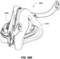
- the patient interface comprises a sealing structure to seal the patient interface against the patient's face.
- the sealing structure comprises a sealing surface configured to form a seal around a periphery of the entrance to the patient's airways, and a loop that folds the sealing structure inwards of an outer perimeter of the sealing structure to form a substantially tube-shaped structure so that the loop is continuous, the loop comprising a portion of the sealing surface.
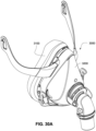
- the patient interface further comprises a positioning and stabilising structure to maintain the sealing structure in sealing contact with an area surrounding an entrance to the patient's airways while maintaining a therapeutic pressure at the entrance to the patient's airways; a plenum chamber pressurised at a pressure above ambient pressure in use; and a gas washout vent configured to allow a flow of patient exhaled CO2 to an exterior of the patient interface to minimise rebreathing of exhaled CO2 by the patient.
- a sealing flap protrudes towards an inner perimeter of the sealing structure, (b) the sealing flap is configured to form a seal against the sides of the nose above the nasal bones and adjacent the sides of the nose above the maxilla, in the depression adjacent the endocanthion of the patient, (c) the sealing flap is configured to avoid sealing against the alar, (d) the portion of the sealing surface has increased flexibility relative to a remaining portion of the loop, (e) the portion of the sealing surface comprises a thinner wall section than a remaining portion of the loop, (f) the portion of the sealing surface comprises a thicker wall section than a remaining portion of the loop, (g) the sealing surface comprises a region of reduced friction to reduce adherence with the patient's face, (h) the region of reduced friction is a frosted surface, (i) the region of reduced friction is adapted to allow the sides of the nose of the patient to slide freely against the sealing surface, (j) the first loop defines an area of the sealing structure adapted to contact the patient's face, (k) the
- Another aspect of one form of the present technology is a patient interface for sealed delivery of a flow of air at a continuously positive pressure with respect to ambient air pressure to an entrance to the patient's airways including at least entrance of a patient's nares, wherein the patient interface is configured to maintain a therapy pressure in a range of about 3 cmH2O to about 40 cmH2O above ambient air pressure in use, throughout the patient's respiratory cycle, while the patient is sleeping, to ameliorate sleep disordered breathing.
- the patient interface comprises a sealing structure to seal the patient interface against the patient's face.
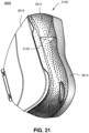
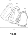
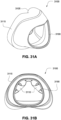
- the sealing structure comprises a face contacting portion adapted to contact around a periphery of the entrance to the patient's airways, and at least a first substantially cylindrical region that has an uninterrupted circumference, wherein a portion of the cylindrical region comprises a portion of the face contacting portion.
- the patient interface further comprises a positioning and stabilising structure to maintain the sealing structure in sealing contact with an area surrounding an entrance to the patient's airways while maintaining a therapeutic pressure at the entrance to the patient's airways; a plenum chamber pressurised at a pressure above ambient pressure in use; and a gas washout vent configured to allow a flow of patient exhaled CO2 to an exterior of the patient interface to minimise rebreathing of exhaled CO2 by the patient.
- the sealing structure comprises unrestrained edges adjacent to ends of the first substantially cylindrical region
- the sealing structure comprises an unrestrained edge all around the periphery of the entrance to the patient's airways except at the first substantially cylindrical region
- the portion of the face contacting portion forms a convex surface adapted to contact the patient's face
- the first substantially cylindrical region is located to contact or be alongside the patient's ala
- the first substantially cylindrical region is located to be substantially parallel to the patient's ala
- the patient interface further comprises a second one of the cylindrical region
- the cylindrical region comprises a second substantially cylindrical region that has a second uninterrupted circumference, wherein a portion of the second cylindrical region comprises a second portion of the face contacting portion
- the first substantially cylindrical region comprises a hollow interior that is adapted to be in fluid communication with the pressure above ambient pressure
- the first substantially cylindrical region comprises two open ends
- the first substantially cylindrical region is adapted to prevent the
- Another aspect of one form of the present technology is a patient interface for sealed delivery of a flow of air at a continuously positive pressure with respect to ambient air pressure to an entrance to the patient's airways including at least entrance of a patient's nares, wherein the patient interface is configured to maintain a therapy pressure in a range of about 3 cmH2O to about 40 cmH2O above ambient air pressure in use, throughout the patient's respiratory cycle, while the patient is sleeping, to ameliorate sleep disordered breathing.
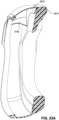
- the patient interface comprises a sealing structure comprising material folded upon itself to form an uninterrupted tubular shape, where only a portion of a circumference of the tubular shape is configured to contact the patient's face; a positioning and stabilising structure to maintain the sealing structure in sealing contact with an area surrounding an entrance to the patient's airways while maintaining a therapeutic pressure at the entrance to the patient's airways; a plenum chamber pressurised at a pressure above ambient pressure in use; and a gas washout vent configured to allow a flow of patient exhaled CO2 to an exterior of the patient interface to minimise rebreathing of exhaled CO2 by the patient, wherein an interior of the tubular shape is adapted to be in fluid communication with the pressure above ambient pressure.
- the uninterrupted tubular shape has an interior surface of the tube and an exterior surface of the tube, the interior surface of the tube is adapted to be exposed to the pressure above ambient pressure in use, a first portion of the exterior surface of the tube is adapted to be exposed to ambient pressure in use, and a second portion of the exterior surface of the tube is adapted to be exposed to the pressure above ambient pressure in use
- the sealing structure further comprises a surface that contacts around a periphery of the patient's airways and the portion of the uninterrupted tubular shape is part of the surface
- the uninterrupted tubular shape is open on at least one end
- the uninterrupted tubular shape is open on two ends
- the uninterrupted tubular shape is adapted to be alongside the patient's ala
- the uninterrupted tubular shape is adapted to contact the patient's ala
- the material is folded to form a second uninterrupted tubular shape where only a portion of a circumference of the second uninterrupted tubular shape is configured to contact the patient's face
- Another aspect of one form of the present technology is a patient interface for sealed delivery of a flow of air at a continuously positive pressure with respect to ambient air pressure to an entrance to the patient's airways including at least entrance of a patient's nares, wherein the patient interface is configured to maintain a therapy pressure in a range of about 3 cmH2O to about 40 cmH2O above ambient air pressure in use, throughout the patient's respiratory cycle, while the patient is sleeping, to ameliorate sleep disordered breathing.
- the patient interface comprises a sealing structure to seal the patient interface against the patient's face.
- the sealing structure comprises a first face contacting portion with an unconnected edge at an inner boundary of the sealing structure, a second face contacting portion that is part of a tubular structure, and the first face contacting portion and the second face contacting portion each form part of a continuous membrane that is configured to contact the patient's face around a periphery of the entrance to the patient's airways.
- the patient interface further comprises a positioning and stabilising structure to maintain the sealing structure in sealing contact with an area surrounding an entrance to the patient's airways while maintaining a therapeutic pressure at the entrance to the patient's airways; a plenum chamber pressurised at a pressure above ambient pressure in use; and a gas washout vent configured to allow a flow of patient exhaled CO2 to an exterior of the patient interface to minimise rebreathing of exhaled CO2 by the patient.
- the patient interface further comprises a plurality of the second face contacting portion
- the second face contacting portion is adapted to contact the patient's face adjacent to or on the patient's ala
- the tubular structure is adapted to prevent the continuous membrane from a blowout when the patient interface is internally pressurized and adjusted by the patient.
- a patient interface for sealed delivery of a flow of air at a continuously positive pressure with respect to ambient air pressure to an entrance to the patient's airways including at least entrance of a patient's nares, wherein the patient interface is configured to maintain a therapy pressure in a range of about 3 cmH2O to about 40 cmH2O above ambient air pressure in use, throughout the patient's respiratory cycle, while the patient is sleeping, to ameliorate sleep disordered breathing.
- the patient interface comprises a sealing structure to seal the patient interface against the patient's face.
- the sealing structure comprises a sealing membrane, and a flap attached on a first end to the sealing membrane and attached on a second end to another structure to prevent the sealing membrane from blowing outward due to the therapy pressure.
- the patient interface further comprises a positioning and stabilising structure to maintain the sealing structure in sealing contact with an area surrounding an entrance to the patient's airways while maintaining a therapeutic pressure at the entrance to the patient's airways; a plenum chamber pressurised at a pressure above ambient pressure in use; and a gas washout vent configured to allow a flow of patient exhaled CO2 to an exterior of the patient interface to minimise rebreathing of exhaled CO2 by the patient.
- the sealing membrane and the flap form part of a tubular structure, and/or (b) the sealing membrane is adapted to contact all around a periphery of the entrance to the patient's airways and the flap is only provided for a portion of the periphery.
- a patient interface for sealed delivery of a flow of air at a continuously positive pressure with respect to ambient air pressure to an entrance to the patient's airways including at least entrance of a patient's nares, wherein the patient interface is configured to maintain a therapy pressure in a range of about 3 cmH2O to about 40 cmH2O above ambient air pressure in use, throughout the patient's respiratory cycle, while the patient is sleeping, to ameliorate sleep disordered breathing.
- the patient interface comprises a sealing structure to seal the patient interface against the patient's face.
- the sealing structure comprises a sealing membrane adapted to contact the patient's face around a periphery of the entrance to the patient's airways, and a cylindrical region underlying and attached to the sealing membrane.
- the patient interface further comprises a positioning and stabilising structure to maintain the sealing structure in sealing contact with an area surrounding an entrance to the patient's airways while maintaining a therapeutic pressure at the entrance to the patient's airways; a plenum chamber pressurised at a pressure above ambient pressure in use; and a gas washout vent configured to allow a flow of patient exhaled CO2 to an exterior of the patient interface to minimise rebreathing of exhaled CO2 by the patient.
- the cylindrical region is located adjacent to the patient's ala, (b) the cylindrical region includes an axis that is substantially parallel to the patient's ala, (c) the cylindrical region is adapted to prevent the sealing membrane from blowing away from the entrance to the patient's airways when the plenum chamber is pressurized at the pressure above ambient pressure, and/or (d) the sealing membrane includes an unconnected edge all around a periphery of the entrance to the patient's airways.
- Another aspect of one form of the present technology is a patient interface for sealed delivery of a flow of air at a continuously positive pressure with respect to ambient air pressure to an entrance to the patient's airways including at least entrance of a patient's nares, wherein the patient interface is configured to maintain a therapy pressure in a range of about 3 cmH2O to about 40 cmH2O above ambient air pressure in use, throughout the patient's respiratory cycle, while the patient is sleeping, to ameliorate sleep disordered breathing.
- the patient interface comprises a sealing structure to seal the patient interface against the patient's face.
- the sealing structure comprises a sealing membrane comprising an interior surface and an exterior surface adapted to contact the patient's face around a periphery of the entrance to the patient's airways, and a rib underlying and attached to the interior surface such that the rib resists deformation of the sealing membrane when pressure is applied to the interior surface.
- the patient interface further comprises a positioning and stabilising structure to maintain the sealing structure in sealing contact with an area surrounding an entrance to the patient's airways while maintaining a therapeutic pressure at the entrance to the patient's airways; a plenum chamber pressurised at a pressure above ambient pressure in use; and a gas washout vent configured to allow a flow of patient exhaled CO2 to an exterior of the patient interface to minimise rebreathing of exhaled CO2 by the patient.
- the exterior surface includes a convex portion
- the interior surface has a concave portion
- the concave portion and the convex portion are located directly opposite one another on the exterior surface and interior surface, respectively, and the rib is attached to the interior surface at the concave portion
- the rib is readily crushed by a forced applied to the patient interface to hold the patient interface to the patient
- the patient interface further comprises a plurality of the rib
- the rib is adapted to be adjacent the patient's nose
- the rib is adapted to prevent the sealing membrane from a blowout when the patient interface is internally pressurized and adjusted by the patient, and/or
- the rib is substantially orthogonal to the interior surface.
- FIG. 1 Another aspect of one form of the present technology is a cushion assembly for a patient interface for sealed delivery of a flow of air at a continuously positive pressure with respect to ambient air pressure to an entrance to the patient's airways including at least entrance of a patient's nares, wherein the patient interface is configured to maintain a therapy pressure in a range of about 4 cmH2O to about 30 cmH2O above ambient air pressure in use, throughout the patient's respiratory cycle, while the patient is sleeping, to ameliorate sleep disordered breathing.
- the cushion assembly includes an elastomeric support portion.
- the cushion assembly also includes an elastomeric seal-forming structure supported by the elastomeric support portion and being shaped to be bisected by a sagittal plane that includes a line tangent to the elastomeric seal-forming structure at a superior tangent point and at an inferior tangent point, the elastomeric support portion being more rigid than the elastomeric seal-forming structure.
- a chamber is defined by the elastomeric support portion and the elastomeric seal-forming structure.
- the elastomeric seal-forming structure may include an inner surface forming a boundary for the chamber and may include an outer surface opposite the inner surface.
- the elastomeric seal-forming structure may also include a first compliant region that includes the superior tangent point and a second compliant region separated from the first compliant region by a support region that is more rigid than the first and second compliant regions.
- the more rigid support region may extend to and may be anchored by the elastomeric support portion.
- the inner surface has a negative curvature when the outer surface has a positive curvature and the inner surface has a positive curvature when the outer surface has a negative curvature.
- FIG. 1 Another aspect of one form of the present technology is a cushion assembly for a patient interface for sealed delivery of a flow of air at a continuously positive pressure with respect to ambient air pressure to an entrance to the patient's airways including at least entrance of a patient's nares, wherein the patient interface is configured to maintain a therapy pressure in a range of about 4 cmH2O to about 30 cmH2O above ambient air pressure in use, throughout the patient's respiratory cycle, while the patient is sleeping, to ameliorate sleep disordered breathing.
- the cushion assembly may include an elastomeric support portion and an elastomeric seal-forming structure.
- the elastomeric seal-forming structure may be supported by the elastomeric support portion and may be shaped to be bisected by a sagittal plane that includes a line tangent to the elastomeric seal-forming structure at a superior tangent point and at an inferior tangent point, the elastomeric support portion being more rigid than the elastomeric seal-forming structure.
- the elastomeric seal-forming structure may include a first compliant region that includes the superior tangent point and a second compliant region separated from the first compliant region by a spring region that has a greater elastomeric wall thickness than the first and second compliant regions.
- the spring region may be tapered so that the elastomeric wall thickness increases in the direction toward the support portion.
- the spring region may have a curvature extending from the seal-forming structure to the support portion.
- FIG. 1 Another aspect of one form of the present technology is a cushion assembly for a patient interface for sealed delivery of a flow of air at a continuously positive pressure with respect to ambient air pressure to an entrance to the patient's airways including at least entrance of a patient's nares, wherein the patient interface is configured to maintain a therapy pressure in a range of about 4 cmH2O to about 30 cmH2O above ambient air pressure in use, throughout the patient's respiratory cycle, while the patient is sleeping, to ameliorate sleep disordered breathing.
- the cushion assembly may include an elastomeric seal-forming structure that is shaped to be bisected by a sagittal plane having a line that is tangent to the elastomeric seal-forming structure at a superior tangent point and at an inferior tangent point.
- a saddle-shaped superior region of the elastomeric seal-forming structure may straddle the sagittal plane and may include the superior tangent point.
- the elastomeric seal-forming structure may transition in a cylinder-shaped superior region from the saddle-shaped region to a dome-shaped superior region offset from the sagittal plane.
- An elastomeric wall thickness of the elastomeric seal-forming structure may be greater in the cylinder-shaped superior region than in the saddle-shaped superior region and the dome-shaped superior region.
- Another aspect of one form of the present technology is a cushion assembly for a patient interface for sealed delivery of a flow of air at a continuously positive pressure with respect to ambient air pressure to an entrance to the patient's airways including at least entrance of a patient's nares, wherein the patient interface is configured to maintain a therapy pressure in a range of about 4 cmH2O to about 30 cmH2O above ambient air pressure in use, throughout the patient's respiratory cycle, while the patient is sleeping, to ameliorate sleep disordered breathing.
- the cushion assembly may include an elastomeric seal-forming structure with an inner surface that defines at least part of a boundary of a chamber, the elastomeric seal-forming structure having a posterior central opening and an anterior central opening opposite the posterior central opening, the elastomeric seal-forming structure including a plurality of closed paths concentric to the posterior central opening.
- An elastomeric wall thickness of the elastomeric seal-forming structure may vary along one of the plurality of closed paths.
- the inner surface of a thickened portion of the elastomeric wall along said one of the plurality of closed paths may be curved in the direction of an open path extending from the posterior central opening to the anterior central opening.
- the plurality of closed paths includes an innermost path along which the elastomeric wall thickness of the elastomeric seal-forming structure is invariable.
- FIG. 1 Another aspect of one form of the present technology is a cushion assembly for a patient interface for sealed delivery of a flow of air at a continuously positive pressure with respect to ambient air pressure to an entrance to the patient's airways including at least entrance of a patient's nares, wherein the patient interface is configured to maintain a therapy pressure in a range of about 4 cmH2O to about 30 cmH2O above ambient air pressure in use, throughout the patient's respiratory cycle, while the patient is sleeping, to ameliorate sleep disordered breathing.
- the cushion assembly may include an elastomeric support portion and an elastomeric seal-forming structure.
- the elastomeric seal-forming structure may be supported by the elastomeric support portion, the elastomeric support portion being more rigid than the elastomeric seal-forming structure.
- the elastomeric seal-forming structure may include a nasal bridge region configured to seal against the patient's nasal bridge when the cushion is mounted to the patient's face and compliant region configured to seal against a side of the patient's nose when the cushion is mounted to the patient's face.
- the elastomeric seal-forming structure may also include a support region that separates the nasal bridge surface from the compliant region, the support region being thicker than the nasal bridge region and the compliant region. The support region may be tapered so that the elastomeric wall thickness of the support region increases in the direction toward the support portion.
- FIG. 1 Another aspect of one form of the present technology is a cushion assembly for a patient interface for sealed delivery of a flow of air at a continuously positive pressure with respect to ambient air pressure to an entrance to the patient's airways including at least entrance of a patient's nares, wherein the patient interface is configured to maintain a therapy pressure in a range of about 4 cmH2O to about 30 cmH2O above ambient air pressure in use, throughout the patient's respiratory cycle, while the patient is sleeping, to ameliorate sleep disordered breathing.
- the cushion assembly may include an elastomeric seal-forming structure with an outer surface configured to seal against the patient's face when the cushion is mounted on the patient's face, the elastomeric seal forming structure having an inner surface that opposes the outer surface and defines at least part of a chamber. There may be a central opening in the seal-forming structure configured to receive at least a portion of the patient's nose when the cushion is mounted to the patient's face.
- the seal-forming structure may include a plurality of closed paths concentric to the central opening. An elastomeric wall thickness of the elastomeric seal-forming structure may vary along one of the plurality of closed paths.
- a thickened portion of the elastomeric wall along said one of the plurality of closed paths may have an inner surface facing the chamber that is curved in the direction of an open path extending from a posterior central opening to an anterior central opening.
- the plurality of closed paths may include an innermost path along which the elastomeric wall thickness of the elastomeric seal-forming structure is invariable.
- a cushion assembly for a patient interface for sealed delivery of a flow of gas at a continuously positive pressure with respect to ambient air pressure to an entrance to the patient's airways including at least entrance of a patient's nares, wherein the patient interface is configured to maintain a therapy pressure in a range of about 4 cmH2O to about 30 cmH2O above ambient air pressure in use, throughout the patient's respiratory cycle, while the patient is sleeping, to ameliorate sleep disordered breathing.
- the cushion includes an elastomeric support portion and an elastomeric seal-forming structure that is more flexible than the elastomeric support portion.
- the elastomeric seal-forming structure may include a tubular structure with an uninterrupted circumference.
- the cushion may also include a plenum chamber defined by the elastomeric support portion and the elastomeric seal-forming structure.
- the plenum chamber may be configured to receive the positive pressure gas.
- the tubular structure and the chamber may be bounded by a common interior surface of the elastomeric seal-forming structure.
- FIG. 1 Another aspect of one form of the present technology is a cushion assembly for a patient interface for sealed delivery of a flow of gas at a continuously positive pressure with respect to ambient air pressure to an entrance to the patient's airways including at least entrance of a patient's nares, wherein the patient interface is configured to maintain a therapy pressure in a range of about 4 cmH2O to about 30 cmH2O above ambient air pressure in use, throughout the patient's respiratory cycle, while the patient is sleeping, to ameliorate sleep disordered breathing.
- the cushion assembly includes an elastomeric support portion and an elastomeric seal-forming structure that is more flexible than the elastomeric support portion. The elastomeric seal-forming structure is supported by the elastomeric support portion.
- the elastomeric seal-forming structure may include a connecting portion that extends from an interior surface of the elastomeric seal-forming structure to an interior surface of the elastomeric support portion.
- the cushion may also include a plenum chamber configured to receive the positive pressure air.
- the plenum chamber may be defined by the elastomeric support portion and the elastomeric seal-forming portion.
- the connecting portion may be positioned to resist deformation of the seal-forming structure to prevent a sealing surface of the seal-forming structure from being displaced in an outward direction by pressurized gas in the plenum chamber.
- FIG. 1 Another aspect of one form of the present technology is a cushion assembly for a patient interface for sealed delivery of a flow of gas at a continuously positive pressure with respect to ambient air pressure to an entrance to the patient's airways including at least entrance of a patient's nares, wherein the patient interface is configured to maintain a therapy pressure in a range of about 4 cmH2O to about 30 cmH2O above ambient air pressure in use, throughout the patient's respiratory cycle, while the patient is sleeping, to ameliorate sleep disordered breathing.
- the cushion assembly includes an elastomeric support portion and an elastomeric seal-forming structure that is more flexible than the elastomeric support portion.
- the elastomeric seal-forming structure extends from first end to a second end, wherein the first end is secured to the elastomeric support portion.
- the second end of the elastomeric seal-forming structure is a free end that is unattached to any structure except where the elastomeric seal-forming structure is looped, the second end being fixed in place where the elastomeric seal-forming structure is looped.
- FIG. 1 Another aspect of one form of the present technology is a cushion assembly for a patient interface for sealed delivery of a flow of gas at a continuously positive pressure with respect to ambient air pressure to an entrance to the patient's airways including at least entrance of a patient's nares, wherein the patient interface is configured to maintain a therapy pressure in a range of about 4 cmH2O to about 30 cmH2O above ambient air pressure in use, throughout the patient's respiratory cycle, while the patient is sleeping, to ameliorate sleep disordered breathing.
- the cushion assembly includes an elastomeric support portion and an elastomeric seal-forming structure that is more flexible than the elastomeric support portion.
- a plenum chamber is configured to receive the positive pressure air.
- the plenum chamber is defined by the elastomeric support portion and the elastomeric seal-forming portion.
- a first cross-sectional shape of the elastomeric seal-forming structure is a closed loop, and a second cross-sectional shape of the elastomeric seal-forming structure is open
- Another aspect of one form of the present technology is a patient interface that is moulded or otherwise constructed with a perimeter shape which is complementary to that of an intended wearer.
- An aspect of one form of the present technology is a method of manufacturing apparatus.
- An aspect of certain forms of the present technology is a medical device that is easy to use, e.g. by a person who does not have medical training, by a person who has limited dexterity, vision or by a person with limited experience in using this type of medical device.
- An aspect of one form of the present technology is a portable RPT device that may be carried by a person, e.g., around the home of the person.
- An aspect of one form of the present technology is a patient interface that may be washed in a home of a patient, e.g., in soapy water, without requiring specialised cleaning equipment.
- An aspect of one form of the present technology is a humidifier tank that may be washed in a home of a patient, e.g., in soapy water, without requiring specialised cleaning equipment.
- the methods, systems, devices and apparatus described herein can provide improved functioning in a processor, such as of a processor of a specific purpose computer, respiratory monitor and/or a respiratory therapy apparatus. Moreover, the described methods, systems, devices and apparatus can provide improvements in the technological field of automated management, monitoring and/or treatment of respiratory conditions, including, for example, sleep disordered breathing.
- portions of the aspects may form sub-aspects of the present technology.
- various ones of the sub-aspects and/or aspects may be combined in various manners and also constitute additional aspects or sub-aspects of the present technology.
- the present technology comprises a method for treating a respiratory disorder comprising the step of applying positive pressure to the entrance of the airways of a patient 1000.
- a supply of air at positive pressure is provided to the nasal passages of the patient via one or both nares.
- mouth breathing is limited, restricted or prevented.
- the present technology comprises an apparatus or device for treating a respiratory disorder.
- the apparatus or device may comprise an RPT device 4000 for supplying pressurised air to the patient 1000 via an air circuit 4170 to a patient interface 3000.
- a non-invasive patient interface 3000 in accordance with one aspect of the present technology comprises the following functional aspects: a seal-forming structure 3100, a plenum chamber 3200, a positioning and stabilising structure 3300, a vent 3400, one form of connection port 3600 for connection to air circuit 4170, and a forehead support 3700.
- a functional aspect may be provided by one or more physical components.
- one physical component may provide one or more functional aspects.
- the seal-forming structure 3100 is arranged to surround an entrance to the airways of the patient so as to facilitate the supply of air at positive pressure to the airways.
- the inventors have found that if a patient interface 3000 is unable to comfortably deliver a minimum level of positive pressure to the airways that treatment may be ineffective.
- the patient interface 3000 in accordance with one form of the present technology is constructed and arranged to be able to provide a supply of air at a positive pressure of at least 6 cmH20 with respect to ambient.
- the patient interface 3000 in accordance with one form of the present technology is constructed and arranged to be able to provide a supply of air at a positive pressure of at least 10 cmH20 with respect to ambient.
- the patient interface 3000 in accordance with one form of the present technology is constructed and arranged to be able to provide a supply of air at a positive pressure of at least 20 cmH20 with respect to ambient.
- a seal-forming structure 3100 provides a seal-forming surface, and may additionally provide a cushioning function.
- a seal-forming structure 3100 in accordance with the present technology may be constructed from a soft, flexible, resilient material such as silicone.
- the non-invasive patient interface 3000 comprises a seal-forming portion that forms a seal in use on an upper lip region (that is, the lip superior) of the patient's face.
- the non-invasive patient interface 3000 comprises a seal-forming portion that forms a seal in use on a chin-region of the patient's face.
- a system comprising more than one a seal-forming structure 3100, each being configured to correspond to a different size and/or shape range.
- the system may comprise one form of a seal-forming structure 3100 suitable for a large sized head, but not a small sized head and another suitable for a small sized head, but not a large sized head.
- the seal-forming structure 3100 is constructed from a biocompatible material, e.g. silicone rubber.
- Fig. 4 illustrates a perspective view of a seal-forming structure 3100 separated from a remainder of the patient interface 3000.
- the seal forming structure includes a sealing surface 3105 that is configured to form a seal around a periphery of a patient's airways.
- the seal may be formed around the patient's nose or the patient's nose and mouth.
- the seal forming structure 3100 includes a tie, connecting portion, or loop 3110 that folds the sealing structure 3100 inwards (e.g., towards the patient's face in use) of an outer perimeter 3115 of the sealing structure 3100.
- the outer perimeter 3115 may be generally defined as a wall that supports and/or is formed continuously with the sealing surface 3105.
- the tie 3110 may form a substantially tube-shaped structure 3120 so that the tie 3110 forms a continuous structure (e.g., continuous circumference) with the sealing surface 3105 and the outer perimeter 3115.
- the tie 3110 may include a portion of the sealing surface 3105, a portion of the outer perimeter 3115 and a portion that is neither the sealing surface 3105 nor the outer perimeter 3115.
- the portion that is neither the sealing surface 3105 nor the outer perimeter 3115 may be in the form of a flap or sheet attached or continuous with one end to the sealing surface and at another end with the outer perimeter 3115.
- the tie 3110 may be located to be alongside the patient's nose, e.g., along the alar, above the nasal bone or anywhere in between. Two ties 3110 may be provided on opposite sides of the patient's nose.
- the tie 3110 may be open internally, including one or both ends, so that the tie 3110 is internally pressurized (e.g., in fluid communication) with the patient's treatment pressure in use.
- the tie 3110 may extend only partially around the periphery of the seal forming structure 3100.
- the tie 3110 and the seal forming structure 3100 do not form a closed, pressurizable structure (e.g., a bladder) such that the space between the tie 3110 and the seal forming structure 3100 is open to the pressure in the interior of the patient interface 3000.
- a closed, pressurizable structure e.g., a bladder
- the seal forming structure 3100 has an edge and the tie 3110 holds the edge to prevent blowout at the edge.
- Areas of the sealing surface 3105 other than the tie 3110 may include a sealing flap 3125 that protrudes inwards towards an inner perimeter of the sealing structure 3100.
- the sealing flap 3125 may have an unconnected edge at or near a radially inner portion of the sealing surface 3105.
- the sealing flap 3125 may include a portion 3125a that is configured to form a seal against the sides of the nose above the nasal bones of the patient.
- the sealing flap 3125 may be structured to avoid sealing against the alar, e.g., by being spaced sufficiently far radially outward with respect to the alar to avoid or minimize contact with the alar.
- Fig. 5 illustrates a substantially opposite perspective view of the seal forming structure 3100 than that illustrated in Fig. 4 .
- the substantially tube-shaped structure 3120 may be more readily apparent from this view.
- Fig. 5A illustrates the tie 3110 with a closed end 3111.
- This figure also illustrates the seal forming structure 3100 without an underlying cushion, and thus the seal forming structure 3100 may be referred to as a single layer cushion.
- Fig. 6 illustrates a plan view of the seal forming structure 3100 and serves as the basis for two section views illustrated in Figs. 7 and 8 .
- Fig. 7 is a cross-section taken through the tie 3110.
- the substantially tube-shaped structure 3120 may be more readily discerned from this view.
- the tie 3110 includes a relatively thick portion 3130 and a relatively thin portion 3135.
- the relatively thick portion 3130 may be between 1 mm and 2 mm thick, or between 1.3 mm and 1.7 mm thick, or about 1.5 mm thick.
- the relatively thin portion 3135 may be between 0.2 mm and 0.8 mm thick, or between 0.4 mm and 0.6 mm thick, or about 0.5 mm thick.
- the relatively thick portion 3130 may be about 2.5 to 5 times as thick as the relatively thin portion 3135, or about 2.8 to 3.3 times as thick as the relatively thin portion 3135, or three times as thick as the relatively thin portion 3135.
- the relatively thick portion 3130 is illustrated to include the outer perimeter 3115 and most of the sealing surface 3105 at the tie 3110.
- the relatively thin portion 3135 folds the sealing structure inwards and connects back to the seal forming structure 3100 at a connection point 3165 that is at or near a hinge structure 3140.
- the hinge structure 3140 is illustrated as a localized, relatively thin strip or line that may provide preferential bending or flexing at a predetermined location, which may provide flexibility for the seal forming structure 3100 to conform to the patient's face.
- the relatively thick portion 3130 may provide sufficient resilience to provide an effective seal against the patients face.
- the relatively thin portion 3135 may provide resistance to the sealing surface 3105 blowing out under pressure while not causing the sealing surface 3105 to have too much rigidity and be too stiff to form an effective seal.
- the thicknesses of the relatively thick portion 3130 and the relatively thin portion 3135 could be the reverse of what is illustrated in Fig. 7 .
- the relatively thin portion 3135 could be extended to encompass the sealing surface 3105. Any combination of thicknesses may be employed to achieve a desired combination of sealing ability and resistance to blow out.
- connection point 3165 may be determined based upon the desired force to be applied by, or desired resilience of, the tie 3110. For example, as illustrated in Fig. 7A , the angle 3170 formed by the relatively thin portion 3135 may be varied. As the angle 3170 is varied, the tension in the relatively thin portion 3135 will also vary. The angle 3170 can thus be optimized to prevent blowout and/or for patient comfort.
- the angle 3170 may be predetermined in several ways. For example, if the seal forming structure 3100 is a single moulded piece, the mould used to form the seal forming structure 3100 will determine the angle 3170. Different angles can be achieved with different moulds. Alternatively, the relatively thin portion 3135 may be manufactured in an un-connected state so that the connection point 3165 is formed in a later assembly step.
- the connection point 3165 could be a mechanical connection or an adhesive bond. If an adhesive bond is used, the connection point 3165 may be continuously varied within an acceptable range of attachment. Alternatively, a mechanical attachment could be used.
- Figs. 7B-7I illustrate exemplary mechanical attachments. In Figs.
- connection point 3165 is keyed so that different angles can be achieved in a single connection point 3165.
- Figs. 7B and 7C illustrate a first connection orientation of the keyed connection and Figs. 7D and 7E illustrate a second connection orientation of the keyed connection.
- Figs. 7F-7I multiple discrete connection points 3165 are provided. The connection point 3165 that is selected will determine the angle 3170.
- Figs. 7F and 7G illustrate a first discrete connection of the discrete connection points and Figs. 7H and 7I illustrate a second discrete connection of the discrete connection points.
- the particular geometry illustrated in Figs. 7B-7I is exemplary only and should not be considered limiting. Other keyed or discrete connection geometries may be used.
- the tie 3110 may be positioned to contact a side wall of the nose including the alar.
- the tie 3110 may also provide a continuous surface to maintain contact with the sides of the nose above the nasal bones of the patient.
- Fig. 8A illustrates a cross-section taken through a vertical plane in Fig. 6 .
- the tie 3110 is attached to the wall forming the outer perimeter 3115 at an attachment portion 3145.
- the attachment portion 3145 is a continuous portion of the tie 3110, which can be achieved by moulding the seal forming structure 3100 in one piece.
- the attachment portion 3145 may also be achieved in any other convenient manner, e.g., by fastening a free end of the tie 3110 using some form of mechanical or chemical fastening like adhesive.
- the attachment portion 3145 along with the overall length of the tie 3110, may be chosen such that sufficient tension is provided to the tie 3110 to counteract a blowout of the sealing surface 3105 when pressure, e.g., therapy pressure, acts on an interior surface of the tie 3110 and the seal forming structure 3100 is pulled away from the patient's face and/or when insufficient headgear tension exists.
- pressure e.g., therapy pressure
- the sealing surface 3105 may be a region of (relatively) reduced friction. This may be achieved by providing a so-called frosted surface. With a region of reduced friction, the sealing surface may adhere to the patient's face less than without the region of reduced friction. The region of reduced friction may be provided as part of the tie 3110 to allow the side(s) of the patient's nose to slide freely along the sealing surface 3105 and/or the tie 3110.
- Figs. 8A - 8G also illustrate various cross-sections of Fig. 6 where the intersections of the cross-sections show that the seal forming structure 3100 includes various saddles and domes.
- the intersections of the various cross-sections are referred to herein by their two-letter combination.
- intersection AB the intersection of the cross-section taken along line 8A-8A and the cross-section taken along line 8B-8B is referred to as intersection AB.
- Intersection AB is taken at a first dome region that is configured to contact the patient's nasal ridge inferior to the patient's sellion.
- Intersection AC is taken at a first saddle region that is configured to contact the patient's nasal ridge at a position inferior to intersection AB.
- Intersection AD is taken at a second saddle region that is configured to contact the patient's lip inferior and/or supramenton.
- Intersection EF is taken at a second dome region that is configured to contact the patient outside of but proximal to the patient's mouth, near the cheilion.
- Intersection EG is taken in a third saddle region that is configured to contact the patient's cheek adjacent the patient's nasal ala.
- the first dome region has relatively large curvature along both cross sections and the second dome region has relatively small curvature along both cross section.
- the first saddle region has relatively large curvature along both cross-sections and the third saddle region has relatively small curvature along line 8E-8E and relatively large curvature along line 8G-8G.
- the second saddle region has curvature that is between the first saddle region and the third saddle region along line 8D-8D and line 8A-8A is similar to that along line 8G-8G.
- Fig. 9 illustrates additional aspects of the present technology.
- Fig. 9 illustrates the tie 3110 underlying the sealing surface 3105.
- the tie 3110 is illustrated mostly as a dashed line. This configuration may be achieved by attaching or forming a strip or tube of material underneath the sealing surface 3105.
- the underlying tie 3110 may be more readily apparent in Fig. 10 .
- Fig. 9 also illustrates a flap 3150 that may extend from the sealing surface 3105 generally near the tie 3110 and/or the patient's nose. Such a flap 3150 may aid in sealing and/or comfort related to the patient's nose, above the maxilla and adjacent the endocanthion. This area of the patient's face may be difficult to seal with some known devices. Alternatively, the flap 3150 may extend from the tie 3110, which may fix the position of the flap 3150 with respect to the tie 3110.
- Fig. 11 illustrates a simplified representation of the tie 3110 as a substantially tube shaped structure 3120 with the flap 3150 extending therefrom.
- Fig. 12 illustrates a simplified representation of the substantially tube-shaped structure 3120 illustrated in Fig. 11 attached to a seal forming structure 3100.
- the substantially tube-shaped structure 3120 may be fabricated separately and fastened to the seal forming structure 3100.
- Fig. 13 illustrates how the substantially tube-shaped structure 3120 provides compliance to allow the seal forming structure 3100 to adapt to a patient's face. Even while compliant, the present technology may prevent a blowout.
- Blowout may be understood to refer to the deformation of the seal forming structure 3100 that is caused, at least in part, by the pressure differential resulting from the application of pressure during therapy such that the sealing surface 3105 is displaced from sealing contact with the patient's face.
- the patient may pull the patient interface 3000 away from the face during therapy (i.e., while pressure is being applied) and when the patient interface 3000 is displaced from the patient's face by the patient, the force of the therapy pressure may cause the seal forming structure 3100 to deform.
- the sealing surface 3105 of the seal forming structure 3100 may be displaced due to deformation such that an ineffective seal is formed and pressurized gas leaks from the seal forming structure 3100.
- the internal pressurisation of the plenum chamber 3200 it is possible for the internal pressurisation of the plenum chamber 3200 to be disturbed and cause a pressure gradient proximal to the sealing flap 3125.
- the pressure gradient may provide a force, which may ultimately lead to blow out of the sealing flap.
- Displacement of the sealing flap during blow out may move the sealing flap into a position that interrupts seal by forming leak paths when the sealing structure is again repositioned onto the face.
- blowout of the seal forming structure 3100 occurs at regions proximal to the patient's eyes (e.g., when the sealing surface 3105 proximal to the frontal process of the maxilla is displaced), the pressurized gas may flow towards the patient's, which may be particularly disruptive and bothersome to the patient. Accordingly, it is advantageous to reduce blowout.
- blow out may subject the seal forming structure 3100 to may be in an outward direction, e.g., away from the patient's face. Indeed, in extreme conditions under high internal pressurisation, blow out may include the seal forming structure 3100 folding backwards upon itself.
- the sides of the nose including above the nasal bones, proximal to the frontal process of the maxilla, and lateral cartilage can be highly variable in profile between users.
- the inner edge of the sealing flap 3125 may bend inwards (e.g., into the plenum chamber and orthogonal to the Frankfort horizontal) and deform to follow the profile of the sides of the nose.
- this area may be particularly prone to seal interruptions following blow out. That is, if the sealing flap 3125 is outwardly displaced (e.g., away from the patient's face) during blow out, it is often difficult to return the sealing flap to a sealing position due to resistance from the force of the pressurized gas.
- blow out may also occur in other areas such as the cheek region or at the upper or lower lip regions which are less prone to seal interruption, but these regions have a generally flatter profile substantially along the coronal plane.
- the sealing flap may not move significantly from a position that is required to seal along this plane and often the sealing force provided by the head gear vectors is sufficient to reposition the sealing flap to an orientation required to regain seal.
- the posterior surface of the sealing flap at the sides of the nose region and down the bottom corners of the sealing flaps provides a larger surface area that is more prone to displacement under internal pressurisation.
- dual wall seal forming structures 3100 may be susceptible to blowout
- single wall seal forming structures 3100 such as those disclosed in examples of the present technology, may be particularly susceptible to blowout.
- the absence of an additional undercushion structure supporting the outer, sealing wall may be understood to allow the outer, sealing wall to deform and deflect more easily.
- the undercushion in a dual wall cushion may help to reposition the outer, sealing wall against the patient's face when the patient interface 3000 is repositioned, but this assistance may be absent in a single wall cushion.
- FIGS. 34A and 34B depict examples of related art patient interfaces 3000 in which blowout has occurred.
- the seal forming structure 3100 can be seen deformed such that the sealing surface 3105 at a blowout region BR1 is displaced from the patient's nose.
- the seal forming structure 3100 can be seen deformed such that the sealing surface 3105 at another blowout region BR2 is displaced from the side of the patient's nose, e.g ., proximal to the frontal process of the maxilla (see FIG. 2H ).
- FIG. 34B depicts displacement of the sealing surface 3105 of the seal forming structure 3200 at a blowout region BR2 at the side of the patient's nose, e.g., proximal to the frontal process of the maxilla.
- the patient interface 3000 is a full-face patient interface that seals around the nose and mouth.
- Such patient interfaces may be particularly susceptible to blowout because the relatively elongate lateral portions may be less supported at intermediate regions and blowout may occur in these regions.
- the force vectors of the positioning and stabilising structure 3300 may be directed generally parallel to the Frankfort horizontal plane or the sagittal plane. Thus, these force vectors may not be directed to impart a force to the seal forming structure 3100 that is generally normal to the frontal process of the maxilla in an inward direction to thereby resist the deformation of the seal forming structure 3100 that results in blowout.
- the force of the therapy pressure that causes deformation of the seal forming structure 3100 may have a magnitude and direction that cannot be adequately opposed by the force vectors from the positioning and stabilizing structure 3100.
- the phenomenon of blowout may be especially relevant for full-face patient interfaces, it should also be understood that nasal patient interfaces may also be susceptible to blowout based on the same principles. Accordingly, the ties 3110 disclosed herein may be incorporated with nasal and full-face patient interfaces to resist blowout.
- the sealing surface 3105 may be understood to broadly refer to the region on the seal forming structure 3100 where a seal may be intended to occur. Since the anthropometry of each patient's head and face is different, the seal forming structure 3100 may be shaped and dimensioned to provide a comfortable fit and effective seal across a range of patients. Therefore, it should be understood that a seal may be intended to occur across various areas of the seal forming structure 3100 and the sealing surface 3105 may broadly refer to such areas.
- a seal may be formed at a specific portion of the broader area in which a seal is intended to occur. That region at which the seal actually occurs in use may also be understood to be the sealing surface 3105.
- the particular meaning of the sealing surface 3105 may be understood to be subject to the particular contexts in which the term is used, as described above.
- blowout may be understood to refer to the situation in which the sealing surface 3105 where a seal is intended to occur is displaced from the patient's face. When such displacement occurs, at least an effective seal may be prevented and, more severely, no sealing contact may occur at all.
- Fig. 14 illustrates another aspect of the present technology that may prevent the seal forming structure 3100 from a blowout.
- two ribs 3155 are illustrated but any number of ribs may be provided.
- a single rib or three or more ribs may be provided.
- each rib 3155 tends to prevent the seal forming structure 3100, for example the sealing surface 3105, from blowing out.
- the ribs may have the same thickness or different thicknesses.
- one or both ribs 3155 may be about 1mm thick and one or both ribs 3155 may be about 0.5mm thick.
- the ribs may have a variable thickness.
- the sealing surface 3105 may be convex and an opposite side, where the ribs 3155 attach, may be concave.
- the convex and concave surfaces define a thickness of material in that area.
- the ribs 3155 may be provided adjacent to a patient's nose.
- Fig. 15 illustrates a cross section of the seal forming structure 3100 taken perpendicular to a plane of a rib 3155.
- the rib 3155 may be relatively compliant in compression or easily crushed under sealing loads, thus allowing seal forming structure 3100 and/or the sealing surface 3105 to adapt to the patient's face. This is illustrated in Fig. 16 .
- the rib 3155 may provide relatively greater resistance in tension, which may occur when the inside of the seal forming structure 3100, e.g., a surface 3105a opposed to the sealing surface 3105, is pressurized.
- the rib 3155 may tend to resist blowout of the seal forming structure 3100, e.g., the rib 3155 may become a tensile member.
- the ribs 3155 tend to keep the seal forming structure 3100 in an "as moulded" state or shape under a blow out condition.
- Figs. 18 and 19 illustrate an extended flap 3160 that may allow a greater distance D1 vs D2, to accommodate for facial variations where the distance between the sides of the nose and the sealing flap is varied.
- the sealing surface 3105 of the extended flap 3160 may also provide an effective seal against the cheeks.
- the arrows represent possible contact area with the patient.
- This type of structure is generally sealed using a membrane on traditional silicone masks and are prone to blow out when re-adjusting the position of the mask.
- the tie 3110 or rib 3155 may prevent blow out from happening while still allowing the variations in distance due to facial differences to be effectively sealed.
- Fig. 20 illustrates a view similar to Fig. 6 except that patterns are included on the seal forming structure 3100.
- the patterns designate regions 3175 of similar thickness of the seal forming structure 3100.
- Region 3175A may be a relatively thin region, for example, about 0.3 mm. This region may be thin for comfort and compliance at the nasal bridge.
- Region 3175B may be a very thin region, for example, about 0.2 mm. This reduction in thickness relative to region 3175A may reduce tension significantly, which may result in minimal to no facial marking at the nasal bridge.
- the nasal bridge is quite bony for most patients and thus may be prone to marking and/or discomfort.
- Region 3175C may be a semi-thin region, for example, about 1 mm. This region may be semi-thin to prevent pinching at the sides of the nose.
- Region 3175D may be a semi-thick region, for example, about 1.5 mm. This region may seal on the cheeks alongside nose. This area on the face is typically fattier then the sides of the nose or nasal bridge, which allows for a relatively greater seal force to be applied without discomfort.
- the semi-thick region may also provide for more structural rigidity than thinner regions.
- Region 3175E may be a thick region, for example, about 2.0 mm. This thicker peripheral region may provide a more rigid outer wall to provide support for the inner portion of the cushion. Region 3175E may act like an undercushion of prior dual layer cushion designs, e.g., the region 3175E may support the portion(s) of the seal forming structure 3100 that contacts the patient's face. For example, region 3175E may provide support to region 3175D and/or 3175F (discussed below).
- the overall cross sectional shape of the cushion may be curved to provide an air (pressure) assisted spring for seal and compliance.
- This configuration may provide an advantage over the previous thick undercushions of prior masks because the disclosed configuration with this thick region may still be able to compress to provide a level of compliance to support forming a seal. This may increase the overall distance range in which the cushion can compress when compared to previous dual layer designs.
- Region 3175F may be a thin membrane region, for example, about 0.3 - 0.5 mm.
- the portion that seals below the lower lip may be thin, for example, about 0.3 mm, to allow for movement of the lower jaw. Such a thin membrane region may also provide a lighter load against the patient's gums for comfort.
- the portion of region 3175F adjacent region 3175D is where the ties 3110 are positioned.
- This portion of region 3175F may be thin, for example, about 0.5 mm, to allow compression of the ties 3110.
- the portion of region 3175F configured to contact on the sides of the patient's mouth may be about 0.5 mm and may act like the sealing membrane layer of the dual layer cushions, which maintain a seal with micro variations of the facial profile and movement during sleep.
- regions 3175 may smoothly transitions in relative thickness from region to region and thus the borders between regions are approximations. This may be advantageous because it limits the ability to identify thick and thin regions by the naked eye, which may also be more aesthetically pleasing. However, distinct transitions may also be provided.
- WO 2006/074513 discloses cushions.
- a thicker undercushion and thinner membrane layer are disclosed.
- the thinner membrane provides a light seal on the face under pressure (i.e. inflates), while the undercushion provides structural support to support sealing.
- the curved cross section provides a pressure assisted spring to support seal under headgear tension.
- a seal forming structure 3100 with the one or more of the regions 3175 described above may have only a single layer, which may combine functions of the membrane and undercushion of WO 2006/074513 .
- the maximum thickness of the cross section of the regions 3175 e.g., region 3175E
- region 3175E may be thinner than the maximum thickness of the undercushion of WO 2006/074513 .
- combining the undercushion and membrane into a single layer allows for sufficient structural rigidity to hold the shape of the cushion and support sealing action.
- the reduced maximum thickness allows the single layer of the seal forming structure 3100 to be compressible by a greater distance compared to the previous dual layer design, thereby allowing for added compliance before bottoming out.
- Fig. 21 discloses a similar system but with two ribs 3155 having been incorporated, where the ribs configured to be on opposed sides of a patient's nose. Only one rib is visible in Fig. 21 . These ribs act as ties that prevent the flexible clip and attached foam seal from blowing out. Although ribs 3155 are illustrated, ties 3110 could be substituted for the ribs 3155.
- the seal forming structure 3100 may comprise a cushion 3810, which may be made with foam.
- the cushion defines a single area that peripherally covers the patient's nose, in the case of a nasal mask, and the nose and mouth, in the case of a full face mask.
- the foam cushion may, for example, be made from any suitable material such as one or more of the following example materials: Polyethylene, Polyurethane, Ethylene vinyl acetate (EVA).
- EVA Ethylene vinyl acetate
- the foam cushion may be a semi-open closed cell foam, such as one made of polyurethane.
- the cushion of semi-open cell foam may have a limited permeability such as in the ranges described in more detail in International Patent Application Publication WO 2014/117227 .
- the cushion 3810 may have a substantially triangular or pear-like shape with a sealing face that follows the contours of a user's face.
- the foam cushion is designed to be attached to a first support (e.g., flexible) clip 3812 that is itself attached to a second, more rigid, clip 3814 (as shown in Fig. 22 ) or directly to the mask shell 3816.
- the first support clip 3812 can be a flexible clip that is more rigid than the foam cushion, but softer or more flexible than the second clip 3814. It is the combination of the foam and a flexible clip that define the physical properties of the overall sealing interface.
- the flexible clip allows the interface to accommodate major variations, and to successfully conform to the contours of the patient's face.
- the compliant nature of the foam cushion provides micro-adjustment and forms a comfort interface layer that interacts with the patient's skin.
- the first support clip 3812 may be prone to blowing out due to its flexible and compliant nature.
- Fig. 21 illustrates another aspect of the present technology that may prevent the first support clip 3812 and the attached cushion 3810 from a blowout.
- the configuration illustrated includes two ribs 3155 (only one being visible due to the symmetric nature and orientation of the figure) but any number of ribs may be provided.
- a single rib or three or more ribs may be provided.
- each rib 3155 tends to prevent the first support clip 3812 and the attached cushion 3810 from blowing out by functioning as a tensile member.
- the ribs may have the same thickness or different thicknesses.
- one or both ribs 3155 may be about 1mm thick and one or both ribs 3155 may be about 0.5mm thick.
- the ribs may have a variable thickness.
- the ribs 3155 may be provided adjacent to a patient's nose.
- Fig. 21 illustrates a side view of a cushion assembly 3800 comprising the seal forming structure 3100 including a mask shell 3816, a permanently attached flexible first supporting clip 3812 and a foam cushion 3810.
- the flexible first supporting clip may be fixed to the mask shell 3816 via a pair of ribs 3155 that act as ties to prevent blow out.
- the ribs 3155 may be relatively compliant in compression or easily crushed under sealing loads, thus allowing the seal forming structure 3100 to adapt to the patient's face.
- the tension provided by the ribs 3155 may be adjusted by altering any one or more of its material composition, geometry or position of the ribs 3155.
- Fig. 23 illustrates the foam cushion 3810 and flexible first supporting clip 3812 where the patient contacting surface is visible.
- Fig. 23A is a cross-section taken along a vertical plane of symmetry through Fig. 23 and illustrates the foam cushion, flexible first supporting clip 3812 and rib 3155.
- the seal forming structure 3100 may comprise a pair of ties 3110 to prevent blow out of the first support clip 3812.
- Each tie 3110 is formed by an inward fold of the flexible supporting clip 3812 of an outer perimeter to form a connection point 3165.
- the tie 3110 may form a substantially tube-shaped structure 3120.
- the tie forms a tie to resist blowing out from internal pressurisation of the plenum chamber.
- the tension provided by the ribs 3155 may be adjusted by altering any one or more of its material composition, geometry or position of the connection point 3165 of position the tie 3110.
- Figs. 24A-27F illustrate a cushion assembly 6000 similar to the seal forming structure 3100 except as noted herein. Like reference numbers are similar to those described above regarding the seal forming structure 3100 and thus further description not repeated here.
- the cushion assembly 6000 illustrated in Figs. 24A-27F may have features generally suitable for use with a nasal mask.
- Fig. 24A illustrates a perspective view of one form of the cushion assembly 6000 separated from a remainder of the patient interface 3000.
- Fig. 24B illustrates a perspective view of the cushion assembly 6000 with a shell 6005.
- the cushion assembly 6000 may be attached to the shell 6005 by any means (e.g., chemical bond, mechanical connection, or adhesive bond).
- the cushion 6000 may be removable from the shell 6005 or permanently attached to the shell 6005.
- the cushion assembly 6000 may be more pliable than the shell 6005.
- the cushion assembly 6000 may be made of silicone material, while the shell 6005 may be made of a polycarbonate material. It is contemplated that portions or all of the cushion assembly 6000 may be frosted, while the shell 6005 may be transparent. Alternatively, the cushion assembly 6000 and the shell 6005 may be entirely transparent.
- the cushion assembly 6000 may include an elastomeric seal-forming structure 6010 and an elastomeric supporting structure 6015 that supports the seal-forming structure 6010.
- the seal-forming structure 6010 may be more pliable than the supporting structure 6015, and the supporting structure 6015 may be more pliable than the shell 6005
- the seal-forming structure 6010 may include the sealing flap 3125 and may be configured to form a seal around a periphery of a patient's airways.
- the seal may be formed around the patient's nose or the patient's nose and mouth.
- the seal-forming structure 6010 may form a central opening (or posterior central opening) 6020 on a posterior side of the cushion assembly 6000 that provides access to an interior of the plenum chamber 3200 through the cushion 6000.
- the tie 3110 is anchored to the supporting structure 6015 at the attachment point 3145.
- the plenum chamber 3200 and an interior of the tub-shaped (or tubular) structure 3120 formed by the tie 3110 and the cushion assembly 6000 may be bounded by the same interior surface of the seal-forming structure 6010.
- the tub-shaped (or tubular) structure 3120 and the plenum chamber 3200 may be bounded by a common surface of the cushion assembly 6000.
- Figs. 25B - 25G also illustrate various cross-sections of Fig. 25A where the intersections of the cross-sections show that the seal-forming structure 6010 includes various saddles and domes.
- the intersections of the various cross-sections are referred to herein by their two-letter combination.
- intersection BC the intersection of the cross-section taken along line 25B-25B and the cross-section taken along line 25C-25C is referred to as intersection BC.
- Intersection BC is taken at a first saddle region that is configured to contact the patient's nasal ridge inferior to the patient's sellion. Along line 25B-25B, the curvature is relatively small and along line 25C-25C the curvature is relatively large. The curvature along line 25B-25B is sufficiently large that the first saddle region is approaching a cylindrical region. The first saddle region may be a cylindrical region if so desired.
- Intersection BD is taken at a second saddle region that is configured to contact the patient's lip superior. Along line 25B-25B the curvature is relatively small compared to along line 25D-25D.
- Intersection CF is taken at a first dome region that is configured to contact the patient's nose adjacent the nasal ridge.
- Intersection FG is taken at a third saddle region formed by the tie 3110 that is configured to contact alongside the patient's nose.
- the curvature along line 25F-25F is relatively small and is approaching zero curvature.
- the curvature along line 25G-25G is relatively large comparted to line 25F-25F.
- the third saddle region is approaching a cylindrical region and thus may be a cylindrical region if preferred.
- Intersection EF is taken at a second dome region that is configured to contact the patient alongside the patient's nasal alar.
- the curvatures along lines 22E-22D and 22F-22F are relatively similar.
- Figs. 27A and 27B illustrate a view of the seal-forming structure 6010 except that patterns are included on the seal-forming structure 6010.
- the patterns designate regions of similar properties and/or thickness of the seal-forming structure 6010.
- Fig. 27B illustrates the positional relationship between the tie 3110 and the different regions.
- the region 6010A (which may be referred to as a nose bridge region) may engage the patient's nose bridge when the patient interface 3000 is mounted on the patient's face.
- the region 6010A may extend from the central opening 6020 to the supporting structure 6015.
- the elastomeric wall thickness of the seal-forming structure 6010 may be thinnest at the region 6010A so that the seal-forming structure 6010 may be most compliant across the patient's nose bridge.
- the elastomeric wall thickness of the seal-forming structure 6010 in the region 6010A may be about 0.25 mm. This may facilitate the reduction of red marks in the vicinity of the patient's nose bridge.
- the portion of the seal-forming structure 6010 in the region 6010A may be unable to maintain its shape when subjected to forces that may occur when the patient interface 3000 is pressed against the patient's face and is moved relative to the patient's face (which may occur during a therapy session).
- the thinness of the seal-forming structure 6010 in the region 6010A may leave the portion of the seal-forming structure 6010 in the region 6010A susceptible to crinkling and/or creasing, which may lead to leakage and/or discomfort.
- a pair of regions 6010B may flank the region 6010A.
- the regions 6010B may extend from the supporting structure 6015 to just short of the central opening 6020 so that a first end 6025 of each region 6010B may be anchored in place, while a second end 6030 of each region 6010B may be free to move in response to a compressive force acting on the seal-forming structure 6010.
- An elastomeric wall thickness of each region 6010B may vary from the first end 6025 to the second end 6030.
- the elastomeric wall thickness of the regions 6010B may be thickest at the first end 6025 and may be thinnest at the second end 6030.
- the elastomeric wall thickness of the first end 6025 may be about 1.35 mm
- the elastomeric wall thickness of the second end 6030 may be about 0.9 mm.
- the elastomeric wall thickness of the seal-forming structure 6010 in each region 6010B may gradually decrease from the first end 6025 to the second end 6030 or may abruptly transition from the first end 6025 to the second end 6030. Either way, the elastomeric wall thickness of the seal-forming structure 6010 in the entirety of each region 6010B may be thicker than the elastomeric wall thickness of the seal-forming structure 6010 in the region 6010A.
- Regions 6010B may be distinct from ribs structured to provide overall support for a cushion.
- the curvature of the seal-forming structure 6010 in the regions 6010B may be different from the curvature (or lack of curvature) of a rib.
- the inner surface of the seal-forming structure 6010 (the surface facing and bounding the plenum chamber 3200) and the outer surface of the seal-forming structure 6010 (the surface opposite the inner surface and facing away from the plenum chamber 3200) may have opposite types of curvature.
- the outer surface of the seal-forming structure 6010 at the same point within the region 6010B will have a negative curvature.
- the curvature of the inner surface may follow the curvature of the outer surface.
- the seal-forming structure 6010 may be structured so that a radius of curvature of the seal-forming structure 6010 may decrease from a "neutral radius of curvature” in response to a compressive force acting on the seal-forming structure 6010.
- the seal-forming structure 6010 in each region 6010B may be biased to "spring" back to the neutral radius of curvature in the absence of the compressive force.
- the "spring action" of the regions 6010B may provide support for the region 6000A to prevent or reduce the crinkling and/or creasing of the portion of the seal-forming structure 3110 in the region 6010A.
- the elastomeric wall thickness in the region 6010A may be so thin that the seal-forming structure 6010 in the region 6010A might not be able to provide any resistance to crinkling and/or creasing when the seal-forming structure 6010 is pressed against the patient's face and/or the seal-forming structure 6010 moves or rubs against the patient's face due to movement during the patient's sleep.
- the "spring force" provided by the region 6010B may act against the "plane of the patient's face" and/or against the sides of the patient's nose. Since the regions 6010B flank the region 6010A, the "spring force” generated by the region 6010B may provide enough support to the region 6010A that the region 6010A is able to at least partially resist crinkling and/or creasing. The regions 6010B may even allow the region 6010A to maintain a seal with the patient's face when the region 6010A experiences some crinkling and/or creasing. This may allow the cushion assembly 6000 to maintain a seal against the patient's face while improving comfort.
- a pair of regions 6010C (which may be referred to as compliant regions) flank the regions 6010B so that each region 6010B is sandwiched between the region 6010A and a respective region 6010C.
- an elastomeric wall thickness of the seal-forming structure 6010 in each region 6010C may vary so that the regions 6010C may taper from the support structure 6015 toward the central opening 6020. It should be understood that the elastomeric wall thickness of the seal-forming structure 6010 in the regions 6010C may be thicker toward the supporting structure 6015 and may be thinner toward the central opening 6020.
- the elastomeric wall thickness in the region 6010C may vary from about 0.25 mm adjacent the central opening 6020 to about 1.30 mm adjacent the supporting structure 6015. Where the region 6010B meets the region 6010C, the elastomeric wall thickness in the region 6010B may always be thicker than the elastomeric wall thickness in the corresponding region 6010C. In addition, the transition from thickest to thinnest elastomeric wall thickness may be abrupt or gradua.
- a pair of regions 6010D may immediately adjacent the central opening 6020.
- the regions 6010D may have the same thickness as the region 6010A (i.e., about 0.25 mm) so that it may function as an energized (e.g., pressure activated) seal against the patient's face.
- the pair of regions 6010D may form approximately one third of the seal-forming structure 6010 and may include the ties 3110.
- a region 6010E (which may be referred to as a lip region) may be configured to engage the patient's face above the patient's upper lip. As illustrated, the cushion assembly 6000 in this region may be curved to avoid encroachment onto the patient's upper lip. In addition, the region 6010E may have the same thickness as the region 6010A and the regions 6010D (i.e., about 0.25 mm). This allows the seal-forming structure 6010 to be more compliant in the region adjacent the patient's upper lip. In addition, just like the region 6010A, the region 6010E may extend from the central opening 6020 to the supporting structure 6015. Accordingly, the regions 6010A, 6010D and 6010E may together form a continuous membrane layer from the inferior side of the seal-forming structure 6010 to the superior side of the seal-forming structure.
- a pair of regions 6010F may be the predominant regions of the seal-forming structure 6010.
- the regions 6010F may have the same function in the "single wall” cushion assembly 6000 as an under-cushion layer would have in a "dual wall” cushion (i.e., provide support for a membrane).
- the regions 6010F may support the regions 6010D and 6010E in which the elastomeric wall thickness is thinnest.
- the elastomeric wall thickness of the seal-forming structure 6010 in the regions 6010F may be varied. In particular, the elastomeric wall thickness may increase toward the supporting structure 6015.
- the elastomeric wall thickness of the regions 6010F may be about 1.0 mm adjacent the regions 6010D and 6010E and may be about 2.0 mm adjacent the supporting portion 3125.
- the transition in elastomeric wall thickness may be gradual or abrupt.
- the regions 6010G may have the greatest elastomeric wall thickness of any region of the seal-forming structure 6010.
- the elastomeric wall thickness of the seal-forming structure 6010 may be between about 1.35 mm to 3.45 mm.
- the elastomeric wall thickness may be between about 1.35 mm to about 2.00 mm.
- One or more subregions within the region 6010G may have an elastomeric wall thickness within a range of about 0.90 mm to about 1.80 mm. It is contemplated that the regions 6010G may have a constant elastomeric wall thickness or may have a varied elastomeric wall thickness that increases toward the supporting structure 6015. If the elastomeric wall thickness is varied, the transition in thickness may be gradual or abrupt.
- Region 6010G may provide a support or base for the sealing flap 3125 and may provide and maintain the overall shape of the seal-forming structure 6010.
- the cushion assembly 6000 may be divided into a left side 6035 and a right side 6040 by a sagittal plane 6045.
- the sagittal plane 6045 and may include a line 6050 that is tangent to the seal-forming structure 6010 at only two points: a first tangent point (superior tangent point) 6055 and a second tangent point (inferior tangent point) 6060.
- the region 6010A may straddle the sagittal plane 6045 and may include the first tangent point 6055. Also, when comparing Figs. 27A and 27B to Figs. 25B-26G , it can be seen that a portion of the region 6010A that includes the first tangent point 6055 may be saddle shaped.
- the regions 6010B may be symmetrical with respect to the sagittal plane 6045.
- each region 6010B may be furthest from the sagittal plane 6045 at the first end 6025 and may be closest to the sagittal plane 6045 at the second end 6030.
- at least a portion of each region 6010B may be located in a region of the seal-forming structure 6010 that transitions from a saddle shape to a dome shape.
- the regions 6010B may be located on a cylindrical shaped portion of the seal-forming structure 6010.
- the regions 6010C may be dome-shaped. Portions of the regions 6010 F and 6010G may also be dome-shaped. The radius of curvature of the dome shape in the region 6010C may be smaller than the radius of curvature of the dome shape in the region 6010F. Also, portions of the regions 6010F and 6010G may be cylinder shaped.
- the region 6010D may straddle the sagittal plane 6045 and may include the second tangent point 6055. Also, when comparing Figs. 27A and 27B to Figs. 25B-26G , it can be seen that a portion of the region 6010D that includes the second tangent point 6055 may be saddle shaped. It is contemplated that the radius of curvature in the region 6010D may be greater than the radius of curvature of the region 6010A.
- the seal-forming structure 6010 may have a continuous surface around the central opening 6020.
- the seal-forming structure 6010 may have a plurality of closed paths 6065 that are concentric to the central opening 6020.
- paths that are concentric to the central opening 6020 may substantially follow the shape of the central opening 6020 and may be a particular distance from the central opening 6020 throughout the path when viewed head-on (i.e., the point of view shown in Fig. 27E).
- Fig. 27E also shows one of the plurality of open paths 6070 extending from the central opening 6020 to the supporting portion 6015.
- Figs. 27F and 27G show an exemplary cushion assembly 6000 with a shell 6005.
- the seal-forming structure 6010 may overhang the support structure 6015 at particular locations in the cushion assembly 6000.
- the seal-forming structure 6010 may have a "sickle" shape.
- the "sickle shape is more clearly depicted in the cross-sections illustrated in Figs. 27H-27M .
- a cross-section of the cushion along a line (for example a line extending through a central region of the cushion as shown in Fig. 27G ) may have a closed loop shape in some regions while the cross-section might have an open shape in other regions.
- the ends of the cushion might both be secured in place.
- the one end of the cushion In the "open shape” portions, the one end of the cushion might be secured in place, while the other end might be a free end that is not secured to anything and may be free to move.
- the supporting structure 6015 may include a pair of flange portions 6075 on opposite sides of the sagittal plane 6045 toward the inferior side of the cushion assembly 6000.
- the flange portions 6075 may extend radially outward from the supporting structure 6015.
- the seal-forming structure 6010 may be attached to the outer edges of the flange portions 6075 so that a compressive force acting on the seal-forming structure 6010 may cause the flange portions 6075 to pivot around a base 6080 of the respective flange portion 6075 in a hinge-like manner.
- each flange portion 6075 may act as a shock absorber when the seal-forming structure 6010 is subject to a compressive force due to, for example, the cushion assembly 6000 being compressed against a patient's head
- the flexibility of the supporting structure 6015 may be related to the distance between an anterior side of the supporting structure 6015 and a posterior side of the supporting structure.
- the supporting structure 6015 may be less pliable when the distance between the anterior side and the posterior side is shorter ( Figs. 27H and 27M ).
- the supporting structure 6015 may be more pliable when the distance between the anterior side and the posterior side is greater ( Figs. 27J and 27L ).
- the supporting structure 6015 may provide more support for the seal-forming structure 6010 at the superior and/or inferior portions of the cushion assembly 6000 than at other portions of the cushion assembly 6000 due to the varied distance between the anterior side and the posterior side of the supporting structure 6015.
- FIGS. 28A to 28M depict an exemplary full-face seal forming structure 3100 that includes the ties 3110.
- the ties 3110 may extend between a first interior surface region 3180 and a second interior surface region 3185.
- the first interior surface region 3180 may be understood to be opposite the sealing surface 3105 of the seal forming structure.
- the second interior surface region 3185 may be understood to be located elsewhere. In the example depicted in FIG. 28k , the second interior surface region 3185 is located on the interior of the seal forming structure 3100. In other examples, the second interior surface region 3185 may be located on the interior of the plenum chamber 3200 such that the tie 3110 extends between the seal forming structure 3100 and the plenum chamber 3200.
- the location of the second interior surface region 3185 may be selected based on the desired directional component of the tension vector of the tie 3100 that resists the blowout force.
- FIGS. 28L and 28M show detailed cross-sectional views and, in particular, the connection point 3165 where the tie 3110 extends from the second interior surface region 3165.
- the connection point 3165 in this example may be curved to reduce stress concentration in this region, thereby reducing the tendency for the tie 3110 to tear.
- the tie 3110 may extend from the second interior surface region 3185 at a distance from a bonding region 3190 where the seal forming structure 3100 is bonded to the plenum chamber 3200 during production. This may prevent damage to the tie 3110 when the seal forming structure 3100 is bonded to the plenum chamber 3200.
- FIGS. 29C to 29E also show how the tie 3110 extends from the second interior surface region 3185 at a distance from the bonding region 3190 and the plenum chamber 3200.
- FIGS. 28J to 28L show where the tie 3110 may extend from the first interior surface region 3180. As can be seen in these examples, the tie 3110 extends from the first interior surface region 3110 near, but not at the sealing flap 3125. However, in alternative examples the tie 3110 may extend from the first interior surface region 3180 closer to or at the edge of the sealing flap 3125.
- FIGS. 30A and 30B depict examples of a full-face patient interface 3000 including a seal forming structure 3100 with features of the present technology, but without a positioning and stabilizing structure 3300 depicted.
- FIGS. 31A to 31M depict another example of the present technology which is a nasal seal forming structure 3100.
- the tie 3110 extends contiguously from the sealing flap 3125. Accordingly, there may not be a defined edge in this region.
- at least a portion of the tie 3110 in such an arrangement may form part of the sealing surface 3105 in use, depending on the patient's facial anthropometry.
- FIGS. 32C to 32E show that in the nasal patient interface 3000 example that the tie 3110 may extend from the second interior surface region 3185 at a further distance from the bonding region 3190 as compared to the full-face patient interface 3000.
- Figs. 33A-33C show a frame (or shroud) 6085 may act as a hub for the entire patient interface system.
- the frame 6085 may be removably coupled to the shell 6005 and may be removably coupled to the stabilizing structure 3300.
- the frame 6085 may be removably coupled to the air circuit 4170.
- the shell 6005 may include a flexible lip seal at a central opening that may seal an air path from the air circuit 4170 to the plenum chamber 3200.
- the cushion assembly 6000 and the shell 6005 may become interchangeable with other cushion assemblies 6000 and shells 6005.
- the modular configuration may allow removal of the patient interface system without having to adjust the support structure 3300.
- Region 7005A referred to herein as a nasal region, may have a thickness of about 0.5 mm, which may prevent crinkling and/or creasing of the seal forming structure 7000 in this region.
- Region 7005B may have a thickness between about 2.9 mm to 3.45 mm.
- the thickness may be 2.9 mm at 7005B2, 3.0 mm at 7005B 1 and 7005B3 and 3.45 mm at 7005B4.
- Region 7005B may provide a support or base for the sealing flap 3125 and may provide and maintain the overall shape of the seal forming structure 7000.
- Region 7005C may have a thickness ranging from 0.95 mm to 2.1 mm. As illustrated, this region may be the predominant region of the cushion. For example, region 7005C may be approximately 50% of the cushion. Thickness of the upper portion of the region 7005C1 may be between 0.95 mm and 1.6 mm whereas thickness of the lower portion of the region 7005C2 may be between 1.25 mm and 2.1 mm. The thickness may be continuously varying between these values to provide a smooth appearance.
- Region 7005D may form approximately one third of the seal forming structure 7000 and may include the ties 3110.
- the thickness may be about 0.35 mm.
- This region may be relatively thin so that it may function as an energized (e.g., pressure activated) seal against the patient's face.
- the side sections 7005D1 may be substantially parallel to the patient's face, which may reduce the likelihood of creasing and thus causing a leak. Such creases may be more likely to occur during dynamic situations, e.g., when the seal is under movement.
- Region 7005F may have a thickness ranging from 1.1 mm to 1.8 mm. This zone may function as a spring and allow for compression on the lip superior to reduce pressure thereon. This region may get progressively stiffer from the center of the lip superior to the corners of the nose (e.g., the alar crest point) where region 7005F is stiffest.
- Region 7005G may be relatively deeper to better accommodate patients that have a relatively high nasal bridge and/or provide a more comfortable seal.
- This region may have a thickness similar to that of region 6005D (e.g., about 0.35 mm) and thus may be a sub-region of region 7005D.
- the seal forming structure 3100 may have advantages in one or more forms of the present technology.
- the human facial structure may include variations from person to person that provide challenges when designing a seal for use with many facial variations.
- the variations may include different shapes of the facial structure (e.g ., differently shaped noses and/or differently curved cheeks) and/or different tissue content (e.g ., more or less fatty tissue). These variations may result in a prior seal forming structure that works very well for one person but poorly for another. Also, perceived comfort may vary from person to person independent of facial structure.
- seal forming structure 3100 With the seal forming structure 3100 described herein, a higher percentage of users may use the seal forming structure 3100 effectively (e.g., a higher percentage of users may have the seal forming structure 3100 form an effective seal and/or a higher percentage of users may perceive the seal forming structure 3100 to be comfortable) than compared to prior seal forming structures.
- the plenum chamber 3200 has a perimeter that is shaped to be complementary to the surface contour of the face of an average person in the region where a seal will form in use. In use, a marginal edge of the plenum chamber 3200 is positioned in close proximity to an adjacent surface of the face. Actual contact with the face is provided by the seal-forming structure 3100.
- the seal-forming structure 3100 may extend in use about the entire perimeter of the plenum chamber 3200.
- the plenum chamber 3200 is constructed from a transparent material, e.g. a transparent polycarbonate.
- a transparent material can reduce the obtrusiveness of the patient interface, and help improve compliance with therapy.
- the use of a transparent material can aid a clinician to observe how the patient interface is located and functioning.
- the plenum chamber 3200 is constructed from a translucent material.
- a translucent material can reduce the obtrusiveness of the patient interface, and help improve compliance with therapy.
- the seal-forming structure 3100 of the patient interface 3000 of the present technology may be held in sealing position in use by the positioning and stabilising structure 3300.
- the positioning and stabilising structure 3300 provides a retention force at least sufficient to overcome the effect of the positive pressure in the plenum chamber 3200 to lift off the face.
- the positioning and stabilising structure 3300 provides a retention force to overcome the effect of the gravitational force on the patient interface 3000.
- the positioning and stabilising structure 3300 provides a retention force as a safety margin to overcome the potential effect of disrupting forces on the patient interface 3000, such as from tube drag, or accidental interference with the patient interface.
- a positioning and stabilising structure 3300 is provided that is configured in a manner consistent with being worn by a patient while sleeping.
- the positioning and stabilising structure 3300 has a low profile, or cross-sectional thickness, to reduce the perceived or actual bulk of the apparatus.
- the positioning and stabilising structure 3300 comprises at least one strap having a rectangular cross-section.
- the positioning and stabilising structure 3300 comprises at least one flat strap.
- a positioning and stabilising structure 3300 is provided that is configured so as not to be too large and bulky to prevent the patient from lying in a supine sleeping position with a back region of the patient's head on a pillow.
- a positioning and stabilising structure 3300 is provided that is configured so as not to be too large and bulky to prevent the patient from lying in a side sleeping position with a side region of the patient's head on a pillow.
- a positioning and stabilising structure 3300 comprises a strap constructed from a laminate of a fabric patient-contacting layer, a foam inner layer and a fabric outer layer.
- the foam is porous to allow moisture, (e.g., sweat), to pass through the strap.
- the fabric outer layer comprises tie material to engage with a hook material portion.
- a positioning and stabilising structure 3300 comprises a strap that is extensible, e.g. resiliently extensible.
- the strap may be configured in use to be in tension, and to direct a force to draw a cushion into sealing contact with a portion of a patient's face.
- the strap may be configured as a tie.
- a positioning and stabilising structure 3300 comprises a strap that is bendable and e.g. non-rigid.
- An advantage of this aspect is that the strap is more comfortable for a patient to lie upon while the patient is sleeping.
- a positioning and stabilising structure 3300 comprises a strap constructed to be breathable to allow moisture vapour to be transmitted through the strap,
- a system comprising more than one positioning and stabilizing structure 3300, each being configured to provide a retaining force to correspond to a different size and/or shape range.
- the system may comprise one form of positioning and stabilizing structure 3300 suitable for a large sized head, but not a small sized head, and another. suitable for a small sized head, but not a large sized head.
- the patient interface 3000 includes a vent 3400 constructed and arranged to allow for the washout of exhaled gases, e.g. carbon dioxide.
- exhaled gases e.g. carbon dioxide.
- vent 3400 in accordance with the present technology comprises a plurality of holes, for example, about 20 to about 80 holes, or about 40 to about 60 holes, or about 45 to about 55 holes.
- the vent 3400 may be located in the plenum chamber 3200.
- the vent 3400 is located in a decoupling structure, e.g., a swivel.
- the patient interface 3000 includes at least one decoupling structure, for example, a swivel or a ball and socket.
- Connection port 3600 allows for connection to the air circuit 4170.
- the patient interface 3000 includes a forehead support 3700.
- the patient interface 3000 includes an anti-asphyxia valve.
- a patient interface 3000 includes one or more ports that allow access to the volume within the plenum chamber 3200. In one form this allows a clinician to supply supplemental oxygen. In one form, this allows for the direct measurement of a property of gases within the plenum chamber 3200, such as the pressure.
- An RPT device 4000 in accordance with one aspect of the present technology comprises mechanical, pneumatic , and/or electrical components and is configured to execute one or more algorithms 4300.
- the RPT device 4000 may be configured to generate a flow of air for delivery to a patient's airways, such as to treat one or more of the respiratory conditions described elsewhere in the present document.
- the RPT device may have an external housing 4010, formed in two parts, an upper portion 4012 and a lower portion 4014. Furthermore, the external housing 4010 may include one or more panel(s) 4015.
- the RPT device 4000 comprises a chassis 4016 that supports one or more internal components of the RPT device 4000.
- the RPT device 4000 may include a handle 4018.
- the pneumatic path of the RPT device 4000 may comprise one or more air path items, e.g., an inlet air filter 4112, an inlet muffler 4122, a pressure generator 4140 capable of supplying air at positive pressure (e.g., a blower 4142), an outlet muffler 4124 and one or more transducers 4270, such as pressure sensors 4272 and flow rate sensors 4274.
- air path items e.g., an inlet air filter 4112, an inlet muffler 4122, a pressure generator 4140 capable of supplying air at positive pressure (e.g., a blower 4142), an outlet muffler 4124 and one or more transducers 4270, such as pressure sensors 4272 and flow rate sensors 4274.
- One or more of the air path items may be located within a removable unitary structure which will be referred to as a pneumatic block 4020.
- the pneumatic block 4020 may be located within the external housing 4010. In one form a pneumatic block 4020 is supported by, or formed as part of the chassis 4016.
- the RPT device 4000 may have an electrical power supply 4210, one or more input devices 4220, a central controller 4230, a therapy device controller 4240, a pressure generator 4140, one or more protection circuits 4250, memory 4260, transducers 4270, data communication interface 4280 and one or more output devices 4290. Electrical components 4200 may be mounted on a single Printed Circuit Board Assembly (PCBA) 4202. In an alternative form, the RPT device 4000 may include more than one PCBA 4202.
- PCBA Printed Circuit Board Assembly
- An RPT device may comprise one or more of the following components in an integral unit. In an alternative form, one or more of the following components may be located as respective separate units.
- An RPT device in accordance with one form of the present technology may include an air filter 4110, or a plurality of air filters 4110.
- an inlet air filter 4112 is located at the beginning of the pneumatic path upstream of a pressure generator 4140.
- an outlet air filter 4114 for example an antibacterial filter, is located between an outlet of the pneumatic block 4020 and a patient interface 3000.
- An RPT device in accordance with one form of the present technology may include a muffler 4120, or a plurality of mufflers 4120.
- an inlet muffler 4122 is located in the pneumatic path upstream of a pressure generator 4140.
- an outlet muffler 4124 is located in the pneumatic path between the pressure generator 4140 and a patient interface 3000.
- a pressure generator 4140 for producing a flow, or a supply, of air at positive pressure is a controllable blower 4142.
- the blower 4142 may include a brushless DC motor 4144 with one or more impellers housed in a volute.
- the blower may be capable of delivering a supply of air, for example at a rate of up to about 120 litres/minute, at a positive pressure in a range from about 4 cmH 2 O to about 20 cmH 2 O, or in other forms up to about 30 cmH 2 O.
- the blower may be as described in any one of the following patents or patent applications: U.S. Patent No. 7,866,944 ; U.S. Patent No. 8,638,014 ; U.S. Patent No. 8,636,479 ; and PCT Patent Application Publication No. WO 2013/020167 .
- the pressure generator 4140 is under the control of the therapy device controller 4240.
- a pressure generator 4140 may be a piston-driven pump, a pressure regulator connected to a high pressure source (e.g. compressed air reservoir), or a bellows.
- Transducers may be internal of the RPT device, or external of the RPT device. External transducers may be located for example on or form part of the air circuit, e.g., the patient interface. External transducers may be in the form of noncontact sensors such as a Doppler radar movement sensor that transmit or transfer data to the RPT device.
- a power supply 4210 may be located internal or external of the external housing 4010 of the RPT device 4000.
- power supply 4210 provides electrical power to the RPT device 4000 only. In another form of the present technology, power supply 4210 provides electrical power to both RPT device 4000 and humidifier 5000.
- an RPT device 4000 includes one or more input devices 4220 in the form of buttons, switches or dials to allow a person to interact with the device.
- the buttons, switches or dials may be physical devices, or software devices accessible via a touch screen.
- the buttons, switches or dials may, in one form, be physically connected to the external housing 4010, or may, in another form, be in wireless communication with a receiver that is in electrical connection to a central controller.
- An output device in accordance with the present technology may take the form of one or more of a visual, audio and haptic unit.
- a visual display may be a Liquid Crystal Display (LCD) or Light Emitting Diode (LED) display.
- An air circuit 4170 in accordance with an aspect of the present technology is a conduit or a tube constructed and arranged to allow, in use, a flow of air to travel between two components such as RPT device 4000 and the patient interface 3000.
- the air circuit 4170 may be in fluid connection with the outlet of the pneumatic block 4020 and the patient interface.
- the air circuit may be referred to as an air delivery tube. In some cases there may be separate limbs of the circuit for inhalation and exhalation. In other cases a single limb is used.
- the air circuit 4170 may comprise one or more heating elements configured to heat air in the air circuit, for example to maintain or raise the temperature of the air.
- the heating element may be in a form of a heated wire circuit, and may comprise one or more transducers, such as temperature sensors.
- the heated wire circuit may be helically wound around the axis of the air circuit 4170.
- the heating element may be in communication with a controller such as a central controller.
- a controller such as a central controller.
- a humidifier 5000 (e.g. as shown in Fig. 3V and 3W ) to change the absolute humidity of air or gas for delivery to a patient relative to ambient air.
- the humidifier 5000 is used to increase the absolute humidity and increase the temperature of the flow of air (relative to ambient air) before delivery to the patient's airways.
- the humidifier 5000 may comprise a humidifier reservoir 5110, a humidifier inlet 5002 to receive a flow of air, and a humidifier outlet 5004 to deliver a humidified flow of air.
- a humidifier reservoir 5110 may be the humidifier inlet 5002 and the humidifier outlet 5004 respectively.
- the humidifier 5000 may further comprise a humidifier base 5006, which may be adapted to receive the humidifier reservoir 5110 and comprise a heating element 5240.
- the humidifier 5000 may comprise a water reservoir 5110 configured to hold, or retain, a volume of liquid (e.g. water) to be evaporated for humidification of the flow of air.
- the water reservoir 5110 may be configured to hold a predetermined maximum volume of water in order to provide adequate humidification for at least the duration of a respiratory therapy session, such as one evening of sleep.
- the reservoir 5110 is configured to hold several hundred millilitres of water, e.g. 300 millilitres (ml), 325 ml, 350 ml or 400 ml.
- the humidifier 5000 may be configured to receive a supply of water from an external water source such as a building's water supply system.
- the water reservoir 5110 is configured to add humidity to a flow of air from the RPT device 4000 as the flow of air travels therethrough.
- the water reservoir 5110 may be configured to encourage the flow of air to travel in a tortuous path through the reservoir 5110 while in contact with the volume of water therein.
- the reservoir 5110 may be removable from the humidifier 5000, for example in a lateral direction as shown in Fig. 3V and Fig. 3W .
- the reservoir 5110 may also be configured to discourage egress of liquid therefrom, such as when the reservoir 5110 is displaced and/or rotated from its normal, working orientation, such as through any apertures and/or in between its subcomponents. As the flow of air to be humidified by the humidifier 5000 is typically pressurised, the reservoir 5110 may also be configured to prevent losses in pneumatic pressure through leak and/or flow impedance.
- the reservoir 5110 comprises a conductive portion 5120 configured to allow efficient transfer of heat from the heating element 5240 to the volume of liquid in the reservoir 5110.
- the conductive portion 5120 may be arranged as a plate, although other shapes may also be suitable. All or a part of the conductive portion 5120 may be made of a thermally conductive material such as aluminium (e.g. approximately 2 mm thick, such as 1 mm, 1.5 mm, 2.5 mm or 3 mm), another heat conducting metal or some plastics. In some cases, suitable heat conductivity may be achieved with less conductive materials of suitable geometry.
- the humidifier 5000 may comprise a humidifier reservoir dock 5130 (as shown in Fig. 3V ) configured to receive the humidifier reservoir 5110.
- the humidifier reservoir dock 5130 may comprise a locking feature such as a locking lever 5135 configured to retain the reservoir 5110 in the humidifier reservoir dock 5130.
- the humidifier reservoir 5110 may comprise a water level indicator 5150 as shown in Fig. 3V-3W .
- the water level indicator 5150 may provide one or more indications to a user such as the patient 1000 or a care giver regarding a quantity of the volume of water in the humidifier reservoir 5110.
- the one or more indications provided by the water level indicator 5150 may include an indication of a maximum, predetermined volume of water, any portions thereof, such as 25%, 50% or 75% or volumes such as 200 ml, 300 ml or 400ml.
- a heating element 5240 may be provided to the humidifier 5000 in some cases to provide a heat input to one or more of the volume of water in the humidifier reservoir 5110 and/or to the flow of air.
- the heating element 5240 may comprise a heat generating component such as an electrically resistive heating track.
- One suitable example of a heating element 5240 is a layered heating element such as one described in the PCT Patent Application Publication No. WO 2012/171072 .
- the heating element 5240 may be provided in the humidifier base 5006 where heat may be provided to the humidifier reservoir 5110 primarily by conduction as shown in Fig. 5B.
- Air In certain forms of the present technology, air may be taken to mean atmospheric air, and in other forms of the present technology air may be taken to mean some other combination of breathable gases, e.g. atmospheric air enriched with oxygen.
- Ambient In certain forms of the present technology, the term ambient will be taken to mean (i) external of the treatment system or patient, and (ii) immediately surrounding the treatment system or patient.
- ambient humidity with respect to a humidifier may be the humidity of air immediately surrounding the humidifier, e.g. the humidity in the room where a patient is sleeping. Such ambient humidity may be different to the humidity outside the room where a patient is sleeping.
- ambient pressure may be the pressure immediately surrounding or external to the body.
- ambient noise may be considered to be the background noise level in the room where a patient is located, other than for example, noise generated by an RPT device or emanating from a mask or patient interface.
- Ambient noise may be generated by sources outside the room.
- APAP therapy in which the treatment pressure is automatically adjustable, e.g. from breath to breath, between minimum and maximum limits, depending on the presence or absence of indications of SDB events.
- Continuous Positive Airway Pressure (CPAP) therapy Respiratory pressure therapy in which the treatment pressure is approximately constant through a respiratory cycle of a patient.
- the pressure at the entrance to the airways will be slightly higher during exhalation, and slightly lower during inhalation.
- the pressure will vary between different respiratory cycles of the patient, for example, being increased in response to detection of indications of partial upper airway obstruction, and decreased in the absence of indications of partial upper airway obstruction.
- Flow rate The volume (or mass) of air delivered per unit time. Flow rate may refer to an instantaneous quantity. In some cases, a reference to flow rate will be a reference to a scalar quantity, namely a quantity having magnitude only. In other cases, a reference to flow rate will be a reference to a vector quantity, namely a quantity having both magnitude and direction. Flow rate may be given the symbol Q. ⁇ Flow rate' is sometimes shortened to simply 'flow'.
- a flow rate may be nominally positive for the inspiratory portion of a breathing cycle of a patient, and hence negative for the expiratory portion of the breathing cycle of a patient.
- Total flow rate, Qt is the flow rate of air leaving the RPT device.
- Vent flow rate, Qv is the flow rate of air leaving a vent to allow washout of exhaled gases.
- Leak flow rate, Ql is the flow rate of leak from a patient interface system or elsewhere.
- Respiratory flow rate, Qr is the flow rate of air that is received into the patient's respiratory system.
- Humidifier will be taken to mean a humidifying apparatus constructed and arranged, or configured with a physical structure to be capable of providing a therapeutically beneficial amount of water (H20) vapour to a flow of air to ameliorate a medical respiratory condition of a patient.
- H20 water
- Leak The word leak will be taken to be an unintended flow of air. In one example, leak may occur as the result of an incomplete seal between a mask and a patient's face. In another example leak may occur in a swivel elbow to the ambient.
- Conducted noise in the present document refers to noise which is carried to the patient by the pneumatic path, such as the air circuit and the patient interface as well as the air therein.
- conducted noise may be quantified by measuring sound pressure levels at the end of an air circuit.
- Radiated noise in the present document refers to noise which is carried to the patient by the ambient air.
- radiated noise may be quantified by measuring sound power/pressure levels of the object in question according to ISO 3744.
- Vent noise in the present document refers to noise which is generated by the flow of air through any vents such as vent holes of the patient interface.
- Patient A person, whether or not they are suffering from a respiratory condition.
- Pressure Force per unit area. Pressure may be expressed in a range of units, including cmH 2 O, g-f/cm 2 and hectopascal. 1 cmH 2 O is equal to 1 g-f/cm 2 and is approximately 0.98 hectopascal. In this specification, unless otherwise stated, pressure is given in units of cmH 2 O.
- the pressure in the patient interface is given the symbol Pm, while the treatment pressure, which represents a target value to be achieved by the mask pressure Pm at the current instant of time, is given the symbol Pt.
- Respiratory Pressure Therapy The application of a supply of air to an entrance to the airways at a treatment pressure that is typically positive with respect to atmosphere.
- Ventilator A mechanical device that provides pressure support to a patient to perform some or all of the work of breathing.
- Silicone or Silicone Elastomer A synthetic rubber.
- a reference to silicone is a reference to liquid silicone rubber (LSR) or a compression moulded silicone rubber (CMSR).
- LSR liquid silicone rubber
- CMSR compression moulded silicone rubber
- SILASTIC included in the range of products sold under this trademark
- Another manufacturer of LSR is Wacker.
- an exemplary form of LSR has a Shore A (or Type A) indentation hardness in the range of about 35 to about 45 as measured using ASTM D2240.
- Polycarbonate a thermoplastic polymer of Bisphenol-A Carbonate.
- Resilience Ability of a material to absorb energy when deformed elastically and to release the energy upon unloading.
- Resilient Will release substantially all of the energy when unloaded. Includes e.g. certain silicones, and thermoplastic elastomers.
- Hardness The ability of a material per se to resist deformation (e.g. described by a Young's Modulus, or an indentation hardness scale measured on a standardised sample size).
- Stiffness (or rigidity) of a structure or component The ability of the structure or component to resist deformation in response to an applied load.
- the load may be a force or a moment, e.g. compression, tension, bending or torsion.
- the structure or component may offer different resistances in different directions.
- Floppy structure or component A structure or component that will change shape, e.g. bend, when caused to support its own weight, within a relatively short period of time such as 1 second.
- Rigid structure or component A structure or component that will not substantially change shape when subject to the loads typically encountered in use.
- An example of such a use may be setting up and maintaining a patient interface in sealing relationship with an entrance to a patient's airways, e.g. at a load of approximately 20 to 30 cmH 2 O pressure.
- an I-beam may comprise a different bending stiffness (resistance to a bending load) in a first direction in comparison to a second, orthogonal direction.
- a structure or component may be floppy in a first direction and rigid in a second direction.
- an apnea is said to have occurred when flow falls below a predetermined threshold for a duration, e.g. 10 seconds.
- An obstructive apnea will be said to have occurred when, despite patient effort, some obstruction of the airway does not allow air to flow.
- a central apnea will be said to have occurred when an apnea is detected that is due to a reduction in breathing effort, or the absence of breathing effort, despite the airway being patent.
- a mixed apnea occurs when a reduction or absence of breathing effort coincides with an obstructed airway.
- Breathing rate The rate of spontaneous respiration of a patient, usually measured in breaths per minute.
- Duty cycle The ratio of inhalation time, Ti to total breath time, Ttot.
- Effort The work done by a spontaneously breathing person attempting to breathe.
- Expiratory portion of a breathing cycle The period from the start of expiratory flow to the start of inspiratory flow.
- Flow limitation will be taken to be the state of affairs in a patient's respiration where an increase in effort by the patient does not give rise to a corresponding increase in flow. Where flow limitation occurs during an inspiratory portion of the breathing cycle it may be described as inspiratory flow limitation. Where flow limitation occurs during an expiratory portion of the breathing cycle it may be described as expiratory flow limitation.
- hypopnea is taken to be a reduction in flow, but not a cessation of flow.
- a hypopnea may be said to have occurred when there is a reduction in flow below a threshold rate for a duration.
- a central hypopnea will be said to have occurred when a hypopnea is detected that is due to a reduction in breathing effort.
- hypopneas either of the following may be regarded as being hypopneas:
- Hyperpnea An increase in flow to a level higher than normal.
- Inspiratory portion of a breathing cycle The period from the start of inspiratory flow to the start of expiratory flow will be taken to be the inspiratory portion of a breathing cycle.
- Patency airway
- Airway patency may be quantified, for example with a value of one (1) being patent, and a value of zero (0), being closed (obstructed).
- PEEP Positive End-Expiratory Pressure
- Peak flow rate ( Qpeak ) The maximum value of flow rate during the inspiratory portion of the respiratory flow waveform.
- Respiratory flow rate, patient airflow rate, respiratory airflow rate (Qr) may be understood to refer to the RPT device's estimate of respiratory airflow rate, as opposed to "true respiratory flow rate” or “true respiratory airflow rate”, which is the actual respiratory flow rate experienced by the patient, usually expressed in litres per minute.
- Vt Tidal volume
- (inhalation) Time (Ti) The duration of the inspiratory portion of the respiratory flow rate waveform.
- Total Time (Ttot) The total duration between the start of one inspiratory portion of a respiratory flow rate waveform and the start of the following inspiratory portion of the respiratory flow rate waveform.
- Typical recent ventilation The value of ventilation around which recent values of ventilation Vent over some predetermined timescale tend to cluster, that is, a measure of the central tendency of the recent values of ventilation.
- Upper airway obstruction includes both partial and total upper airway obstruction. This may be associated with a state of flow limitation, in which the flow rate increases only slightly or may even decrease as the pressure difference across the upper airway increases (Starling resistor behaviour).
- Ventilation A measure of a rate of gas being exchanged by the patient's respiratory system. Measures of ventilation may include one or both of inspiratory and expiratory flow, per unit time. When expressed as a volume per minute, this quantity is often referred to as "minute ventilation”. Minute ventilation is sometimes given simply as a volume, understood to be the volume per minute.
- Adaptive Servo-Ventilator A servo-ventilator that has a changeable, rather than fixed target ventilation.
- the changeable target ventilation may be learned from some characteristic of the patient, for example, a respiratory characteristic of the patient.
- Backup rate A parameter of a ventilator that establishes the minimum breathing rate (typically in number of breaths per minute) that the ventilator will deliver to the patient, if not triggered by spontaneous respiratory effort.
- Expiratory positive airway pressure a base pressure, to which a pressure varying within the breath is added to produce the desired mask pressure which the ventilator will attempt to achieve at a given time.
- Inspiratory positive airway pressure (IPAP) : Maximum desired mask pressure which the ventilator will attempt to achieve during the inspiratory portion of the breath.
- pressure support means the difference which the ventilator aims to achieve, rather than what it actually achieves.
- Servo-ventilator A ventilator that measures patient ventilation, has a target ventilation, and which adjusts the level of pressure support to bring the patient ventilation towards the target ventilation.
- Spontaneous / Timed (S / T) : A mode of a ventilator or other device that attempts to detect the initiation of a breath of a spontaneously breathing patient. If however, the device is unable to detect a breath within a predetermined period of time, the device will automatically initiate delivery of the breath.
- Triggered When a ventilator delivers a breath of air to a spontaneously breathing patient, it is said to be triggered to do so at the initiation of the respiratory portion of the breathing cycle by the patient's efforts.
- the typical recent ventilation Vtyp is the value around which recent measures of ventilation over some predetermined timescale tend to cluster.
- a measure of the central tendency of the measures of ventilation over recent history may be a suitable value of a typical recent ventilation.
- Ala the external outer wall or "wing" of each nostril (plural: alar)
- Alare The most lateral point on the nasal ala.
- Alar curvature (or alar crest) point The most posterior point in the curved base line of each ala, found in the crease formed by the union of the ala with the cheek.
- Auricle The whole external visible part of the ear.
- (nose) Bony framework The bony framework of the nose comprises the nasal bones, the frontal process of the maxillae and the nasal part of the frontal bone.
- (nose) Cartilaginous framework The cartilaginous framework of the nose comprises the septal, lateral, major and minor cartilages.
- Columella the strip of skin that separates the nares and which runs from the pronasale to the upper lip.
- Columella angle The angle between the line drawn through the midpoint of the nostril aperture and a line drawn perpendicular to the Frankfort horizontal while intersecting subnasale.
- Frankfort horizontal plane A line extending from the most inferior point of the orbital margin to the left tragion.
- the tragion is the deepest point in the notch superior to the tragus of the auricle.
- Glabella Located on the soft tissue, the most prominent point in the midsagittal plane of the forehead.
- Lateral nasal cartilage A generally triangular plate of cartilage. Its superior margin is attached to the nasal bone and frontal process of the maxilla, and its inferior margin is connected to the greater alar cartilage.
- Greater alar cartilage A plate of cartilage lying below the lateral nasal cartilage. It is curved around the anterior part of the naris. Its posterior end is connected to the frontal process of the maxilla by a tough fibrous membrane containing three or four minor cartilages of the ala.
- Nares Nostrils
- Nostrils Approximately ellipsoidal apertures forming the entrance to the nasal cavity.
- the singular form of nares is naris (nostril). The nares are separated by the nasal septum.
- Naso-labial sulcus or Naso-labial fold The skin fold or groove that runs from each side of the nose to the corners of the mouth, separating the cheeks from the upper lip.
- Naso-labial angle The angle between the columella and the upper lip, while intersecting subnasale.
- Otobasion inferior The lowest point of attachment of the auricle to the skin of the face.
- Otobasion superior The highest point of attachment of the auricle to the skin of the face.
- Pronasale the most protruded point or tip of the nose, which can be identified in lateral view of the rest of the portion of the head.
- Philtrum the midline groove that runs from lower border of the nasal septum to the top of the lip in the upper lip region.
- Pogonion Located on the soft tissue, the most anterior midpoint of the chin.
- nasal Ridge (nasal) : The nasal ridge is the midline prominence of the nose, extending from the Sellion to the Pronasale.
- Sagittal plane A vertical plane that passes from anterior (front) to posterior (rear) dividing the body into right and left halves.
- Septal cartilage (nasal) : The nasal septal cartilage forms part of the septum and divides the front part of the nasal cavity.
- Subalare The point at the lower margin of the alar base, where the alar base joins with the skin of the superior (upper) lip.
- Subnasal point Located on the soft tissue, the point at which the columella merges with the upper lip in the midsagittal plane.
- Frontal bone includes a large vertical portion, the squama frontalis, corresponding to the region known as the forehead.
- Mandible forms the lower jaw.
- the mental protuberance is the bony protuberance of the jaw that forms the chin.
- Maxilla The maxilla forms the upper jaw and is located above the mandible and below the orbits. The frontal process of the maxilla projects upwards by the side of the nose, and forms part of its lateral boundary.
- Nasal bones are two small oblong bones, varying in size and form in different individuals; they are placed side by side at the middle and upper part of the face, and form, by their junction, the "bridge" of the nose.
- Nasion The intersection of the frontal bone and the two nasal bones, a depressed area directly between the eyes and superior to the bridge of the nose.
- Occipital bone The occipital bone is situated at the back and lower part of the cranium. It includes an oval aperture, the foramen magnum, through which the cranial cavity communicates with the vertebral canal.
- the curved plate behind the foramen magnum is the squama occipitalis.
- Orbit The bony cavity in the skull to contain the eyeball.
- the parietal bones are the bones that, when joined together, form the roof and sides of the cranium.
- Temporal bones are situated on the bases and sides of the skull, and support that part of the face known as the temple.
- Zygomatic bones The face includes two zygomatic bones, located in the upper and lateral parts of the face and forming the prominence of the cheek.
- Diaphragm A sheet of muscle that extends across the bottom of the rib cage. The diaphragm separates the thoracic cavity, containing the heart, lungs and ribs, from the abdominal cavity. As the diaphragm contracts the volume of the thoracic cavity increases and air is drawn into the lungs.
- Larynx The larynx, or voice box houses the vocal folds and connects the inferior part of the pharynx (hypopharynx) with the trachea.
- Lungs The organs of respiration in humans.
- the conducting zone of the lungs contains the trachea, the bronchi, the bronchioles, and the terminal bronchioles.
- the respiratory zone contains the respiratory bronchioles, the alveolar ducts, and the alveoli.
- Nasal cavity The nasal cavity (or nasal fossa) is a large air filled space above and behind the nose in the middle of the face.
- the nasal cavity is divided in two by a vertical fin called the nasal septum.
- On the sides of the nasal cavity are three horizontal outgrowths called nasal conchae (singular "concha") or turbinates.
- nasal conchae singular "concha”
- turbinates To the front of the nasal cavity is the nose, while the back blends, via the choanae, into the nasopharynx.
- Pharynx The part of the throat situated immediately inferior to (below) the nasal cavity, and superior to the oesophagus and larynx.
- the pharynx is conventionally divided into three sections: the nasopharynx (epipharynx) (the nasal part of the pharynx), the oropharynx (mesopharynx) (the oral part of the pharynx), and the laryngopharynx (hypopharynx).
- Anti-asphyxia valve The component or sub-assembly of a mask system that, by opening to atmosphere in a failsafe manner, reduces the risk of excessive CO 2 rebreathing by a patient.
- an elbow is an example of a structure that directs an axis of flow of air travelling therethrough to change direction through an angle.
- the angle may be approximately 90 degrees.
- the angle may be more, or less than 90 degrees.
- the elbow may have an approximately circular cross-section.
- the elbow may have an oval or a rectangular cross-section.
- an elbow may be rotatable with respect to a mating component, e.g. about 360 degrees.
- an elbow may be removable from a mating component, e.g. via a snap connection.
- an elbow may be assembled to a mating component via a one-time snap during manufacture, but not removable by a patient.
- Frame will be taken to mean a mask structure that bears the load of tension between two or more points of connection with a headgear.
- a mask frame may be a non-airtight load bearing structure in the mask. However, some forms of mask frame may also be air-tight.
- Headgear will be taken to mean a form of positioning and stabilizing structure designed for use on a head.
- the headgear may comprise a collection of one or more struts, ties and stiffeners configured to locate and retain a patient interface in position on a patient's face for delivery of respiratory therapy.
- Some ties are formed of a soft, flexible, elastic material such as a laminated composite of foam and fabric.
- Membrane will be taken to mean a typically thin element that has, preferably, substantially no resistance to bending, but has resistance to being stretched.
- Plenum chamber a mask plenum chamber will be taken to mean a portion of a patient interface having walls at least partially enclosing a volume of space, the volume having air therein pressurised above atmospheric pressure in use.
- a shell may form part of the walls of a mask plenum chamber.
- Seal May be a noun form ("a seal”) which refers to a structure, or a verb form ("to seal”) which refers to the effect.
- Two elements may be constructed and/or arranged to 'seal' or to effect 'sealing' therebetween without requiring a separate 'seal' element per se.
- a shell will be taken to mean a curved, relatively thin structure having bending, tensile and compressive stiffness.
- a curved structural wall of a mask may be a shell.
- a shell may be faceted.
- a shell may be airtight.
- a shell may not be airtight.
- a stiffener will be taken to mean a structural component designed to increase the bending resistance of another component in at least one direction.
- a strut will be taken to be a structural component designed to increase the compression resistance of another component in at least one direction.
- Swivel A subassembly of components configured to rotate about a common axis, preferably independently, preferably under low torque.
- the swivel may be constructed to rotate through an angle of at least 360 degrees.
- the swivel may be constructed to rotate through an angle less than 360 degrees.
- the sub-assembly of components preferably comprises a matched pair of cylindrical conduits. There may be little or no leak flow of air from the swivel in use.
- Tie A structure designed to resist tension.
- Vent (noun): A structure that allows a flow of air from an interior of the mask, or conduit, to ambient air for clinically effective washout of exhaled gases.
- a clinically effective washout may involve a flow rate of about 10 litres per minute to about 100 litres per minute, depending on the mask design and treatment pressure.
- Products in accordance with the present technology may comprise one or more three-dimensional mechanical structures, for example a mask cushion or an impeller.
- the three-dimensional structures may be bounded by two-dimensional surfaces. These surfaces may be distinguished using a label to describe an associated surface orientation, location, function, or some other characteristic.
- a structure may comprise one or more of an anterior surface, a posterior surface, an interior surface and an exterior surface.
- a cushion structure may comprise a face-contacting (e.g. outer) surface, and a separate non-face-contacting (e.g. underside or inner) surface.
- a structure may comprise a first surface and a second surface.
- Fig. 3B to Fig. 3F illustrate examples of cross-sections at point p on a surface, and the resulting plane curves.
- Figs. 3B to 3F also illustrate an outward normal vector at p.
- the outward normal vector at p points away from the surface.
- the curvature of a plane curve at p may be described as having a sign (e.g. positive, negative) and a magnitude (e.g. 1/radius of a circle that just touches the curve at p ).
- Negative curvature If the curve at p turns away from the outward normal, the curvature in that direction at that point will be taken to be negative (if the imaginary small person leaves the point p they must walk downhill). See Fig. 3E (relatively small negative curvature compared to Fig. 3F) and Fig. 3F (relatively large negative curvature compared to Fig. 3E ). Such curves are often referred to as convex.
- a description of the shape at a given point on a two-dimensional surface in accordance with the present technology may include multiple normal cross-sections.
- the multiple cross-sections may cut the surface in a plane that includes the outward normal (a "normal plane"), and each cross-section may be taken in a different direction.
- Each cross-section results in a plane curve with a corresponding curvature.
- the different curvatures at that point may have the same sign, or a different sign.
- Each of the curvatures at that point has a magnitude, e.g. relatively small.
- the plane curves in Figs. 3B to 3F could be examples of such multiple cross-sections at a particular point.
- Principal curvatures and directions The directions of the normal planes where the curvature of the curve takes its maximum and minimum values are called the principal directions.
- the maximum curvature occurs in Fig. 3B
- the minimum occurs in Fig. 3F
- Fig. 3B and Fig. 3F are cross sections in the principal directions.
- the principal curvatures at p are the curvatures in the principal directions.
- Region of a surface A connected set of points on a surface.
- the set of points in a region may have similar characteristics, e.g. curvatures or signs.
- Saddle region A region where at each point, the principal curvatures have opposite signs, that is, one is positive, and the other is negative (depending on the direction to which the imaginary person turns, they may walk uphill or downhill).
- Dome region A region where at each point the principal curvatures have the same sign, e.g. both positive (a "concave dome”) or both negative (a “convex dome”).
- Cylindrical region A region where one principal curvature is zero (or, for example, zero within manufacturing tolerances) and the other principal curvature is non-zero.
- Planar region A region of a surface where both of the principal curvatures are zero (or, for example, zero within manufacturing tolerances).
- Edge of a surface A boundary or limit of a surface or region.
- 'path' will be taken to mean a path in the mathematical - topological sense, e.g. a continuous space curve from f (0) to f (1) on a surface.
- a 'path' may be described as a route or course, including e.g. a set of points on a surface. (The path for the imaginary person is where they walk on the surface, and is analogous to a garden path).
- Path length In certain forms of the present technology, ⁇ path length' will be taken to mean the distance along the surface from f(0) to f(1), that is, the distance along the path on the surface. There may be more than one path between two points on a surface and such paths may have different path lengths. (The path length for the imaginary person would be the distance they have to walk on the surface along the path).
- the straight-line distance is the distance between two points on a surface, but without regard to the surface. On planar regions, there would be a path on the surface having the same path length as the straight-line distance between two points on the surface. On non-planar surfaces, there may be no paths having the same path length as the straight-line distance between two points. (For the imaginary person, the straight-line distance would correspond to the distance ⁇ as the crow flies'.)
- a space curve does not necessarily lie in any particular plane.
- a space curve may be considered to be a one-dimensional piece of three-dimensional space.
- An imaginary person walking on a strand of the DNA helix walks along a space curve.
- a typical human left ear comprises a helix, which is a left-hand helix, see Fig. 3Q .
- a typical human right ear comprises a helix, which is a right-hand helix, see Fig. 3R.
- Fig. 3S shows a right-hand helix.
- the edge of a structure e.g. the edge of a membrane or impeller, may follow a space curve.
- a space curve may be described by a curvature and a torsion at each point on the space curve.
- Torsion is a measure of how the curve turns out of a plane. Torsion has a sign and a magnitude.
- the torsion at a point on a space curve may be characterised with reference to the tangent, normal and binormal vectors at that point.
- Tangent unit vector (or unit tangent vector): For each point on a curve, a vector at the point specifies a direction from that point, as well as a magnitude. A tangent unit vector is a unit vector pointing in the same direction as the curve at that point. If an imaginary person were flying along the curve and fell off her vehicle at a particular point, the direction of the tangent vector is the direction she would be travelling.
- Unit normal vector As the imaginary person moves along the curve, this tangent vector itself changes.
- the unit vector pointing in the same direction that the tangent vector is changing is called the unit principal normal vector. It is perpendicular to the tangent vector.
- Binormal unit vector The binormal unit vector is perpendicular to both the tangent vector and the principal normal vector. Its direction may be determined by a right-hand rule (see e.g. Fig. 3P ), or alternatively by a left-hand rule ( Fig. 3O ).
- Osculating plane The plane containing the unit tangent vector and the unit principal normal vector. See Figures 3O and 3P .
- Torsion of a space curve is the magnitude of the rate of change of the binormal unit vector at that point. It measures how much the curve deviates from the osculating plane.
- a space curve which lies in a plane has zero torsion.
- a space curve which deviates a relatively small amount from the osculating plane will have a relatively small magnitude of torsion (e.g. a gently sloping helical path).
- a space curve which deviates a relatively large amount from the osculating plane will have a relatively large magnitude of torsion (e.g. a steeply sloping helical path).
- T2>T1 the magnitude of the torsion near the top coils of the helix of Fig. 3S is greater than the magnitude of the torsion of the bottom coils of the helix of Fig. 3S
- a space curve turning towards the direction of the right-hand binormal may be considered as having a right-hand positive torsion (e.g. a right-hand helix as shown in Fig. 3S ).
- a space curve turning away from the direction of the right-hand binormal may be considered as having a right-hand negative torsion (e.g. a left-hand helix).
- a space curve turning towards the direction of the left-hand binormal may be considered as having a left-hand positive torsion (e.g. a left-hand helix).
- left-hand positive is equivalent to right-hand negative. See Fig. 3T .
- a surface may have a one-dimensional hole, e.g. a hole bounded by a plane curve or by a space curve.
- Thin structures e.g. a membrane
- Thin structures with a hole, may be described as having a one-dimensional hole. See for example the one dimensional hole in the surface of structure shown in Fig. 3I , bounded by a plane curve.
- a structure may have a two-dimensional hole, e.g. a hole bounded by a surface.
- a hole bounded by a surface For example, an inflatable tyre has a two dimensional hole bounded by the interior surface of the tyre.
- a bladder with a cavity for air or gel could have a two-dimensional hole. See for example the cushion of Fig. 3L and the example cross-sections therethrough in Fig. 3M and Fig. 3N , with the interior surface bounding a two dimensional hole indicated.
- a conduit may comprise a one-dimension hole (e.g. at its entrance or at its exit), and a two-dimension hole bounded by the inside surface of the conduit. See also the two dimensional hole through the structure shown in Fig. 3K , bounded by a surface as shown.
- any and all components herein described are understood to be capable of being manufactured and, as such, may be manufactured together or separately.
Claims (13)
- Polsteranordnung (3800, 6000) für eine Patientenschnittstelle zur abgedichteten Abgabe einer Luftströmung mit einem kontinuierlich positiven Druck im Hinblick auf den Umgebungsluftdruck zu einem Eingang zu den Patientenluftwegen, darunter mindestens einem Eingang der Nasenlöcher eines Patienten, wobei die Patientenschnittstelle so konfiguriert ist, dass sie einen Therapiedruck in einem Bereich von etwa 4 cmH2O bis etwa 30 cmH2O über dem Umgebungsluftdruck im Gebrauch über den gesamten Atemzyklus des Patienten beibehält, während der Patient schläft, um schlafbezogene Atmungsstörungen zu mildern, wobei die Polsteranordnung aufweist:einen elastomeren Stützabschnitt (6015);eine elastomere dichtungsbildende Struktur (3100, 6010), die durch den elastomeren Stützabschnitt (6015) gestützt wird, wobei die elastomere dichtungsbildende Struktur (3100, 6010) so geformt ist, dass sie durch eine Saggitalebene (6045) halbiert wird, die eine Tangente (6050) zur elastomeren dichtungsbildenden Struktur (6010) an einem superior gelegenen Tangentenpunkt (6055) und an einem inferior gelegenen Tangentenpunkt (6060) aufweist, wobei der elastomere Stützabschnitt (6015) steifer als die elastomere dichtungsbildende Struktur (3100, 6010) ist, wobei die elastomere dichtungsbildende Struktur (6010) aufweist: einen ersten nachgiebigen Bereich (3175A, 6010A), der den superior gelegenen Tangentenpunkt (6055) aufweist und einen zweiten nachgiebigen Bereich (3175D, 6010C), der vom ersten nachgiebigen Bereich (3175A, 6010A) durch einen Stützbereich (3175C, 6010B) getrennt ist, der steifer als der erste und zweite nachgiebige Bereich (3175A; D; 6010A; C) ist;ein Verbindungsstück (3110), das eine kontinuierliche Struktur mit einer Dichtfläche der dichtungsbildenden Struktur (3100, 6010) bildet und am elastomeren Stützabschnitt (6015) verankert ist; undeine Plenumkammer (3200), die so konfiguriert ist, dass sie die Luft mit positivem Druck aufnimmt, wobei die Plenumkammer (3200) durch den elastomeren Stützabschnitt (6015) und die elastomere dichtungsbildende Struktur (3100, 6010) gebildet ist,wobei die Querschnittform der Polsteranordnung (3800, 6000) am Verbindungsstück (3110) eine geschlossene Schlaufe ist,wobei die Querschnittform der Polsteranordnung (3800, 6000) an allen anderen Abschnitten der elastomeren dichtungsbildenden Struktur (3100, 6010) offen ist,wobei sich der steifere Stützbereich (3175C, 6010B) zum elastomeren Stützabschnitt (6015) erstreckt und durch ihn verankert ist,wobei eine elastomere Wanddicke im steiferen Stützbereich (3175C, 6010B) unveränderlich ist undwobei die elastomere dichtungsbildende Struktur (3100, 6010) eine Innenfläche aufweist, die eine Grenze für die Kammer bildet, und eine Außenfläche entgegengesetzt zur Innenfläche aufweist.
- Polsteranordnung (3800, 6000) nach Anspruch 1, wobei eine elastomere Wanddicke der elastomeren dichtungsbildenden Struktur (3100, 6010) im ersten nachgiebigen Bereich (3175A, 6010A) gleich einer elastomeren Wanddicke der elastomeren dichtungsbildenden Struktur (3100, 6010) im zweiten nachgiebigen Bereich (3175D, 6010C) ist.
- Polsteranordnung (3800, 6000) nach Anspruch 1 oder 2, wobei sich der erste nachgiebige Bereich (3175A, 6010A) der elastomeren dichtungsbildenden Struktur (3100, 6010) zum elastomeren Stützabschnitt (6015) erstreckt und sich der zweite nachgiebige Bereich (3175D, 6010C) der elastomeren dichtungsbildenden Struktur (3100, 6010) nicht zum elastomeren Stützabschnitt (6015) erstreckt.
- Polsteranordnung (3800, 6000) nach einem der Ansprüche 1 bis 3, wobei das Verbindungsstück (3110) die Form einer Röhrenstruktur hat.
- Polsteranordnung (3800, 6000) nach einem der Ansprüche 1 bis 4, wobei der steifere Stützbereich (3175C, 6010B) an einer Stelle positioniert ist, die zum Verbindungsstück (3110) superior gelegen ist.
- Polsteranordnung (3800, 6000) nach einem der Ansprüche 1 bis 5, wobei das Verbindungsstück (3110) so positioniert ist, dass es einer Ausblaskraft widersteht, die auf die elastomere dichtungsbildende Struktur (3100, 6010) wirkt.
- Polsteranordnung (3800, 6000) nach einem der Ansprüche 1 bis 6, wobei die elastomere dichtungsbildende Struktur (3100, 6010) ferner einen inferior gelegenen Bereich (6010E) aufweist, der den inferior gelegenen Tangentenpunkt (6060) aufweist, und wobei die elastomere Wanddicke der elastomeren dichtungsbildenden Struktur (3100, 6010) im inferior gelegenen Bereich (6010E) gleich der elastomeren Wanddicke im ersten nachgiebigen Bereich (6010A) ist.
- Polsteranordnung (3800, 6000) nach Anspruch 7, wobei die elastomere dichtungsbildende Struktur (3100, 6010) ferner einen Zwischenstützbereich (3175E, 6010F) aufweist, der zwischen dem zweiten nachgiebigen Bereich (3175D, 6010C) und dem inferior gelegenen Bereich (6010E) positioniert ist, und wobei die elastomere Wanddicke der elastomeren dichtungsbildenden Struktur (3100, 6010) im Zwischenstützbereich (3175E, 6010F) größer als die im ersten nachgiebigen Bereich (3175A, 6010A) ist.
- Polsteranordnung (3800, 6000) nach Anspruch 8, wobei die elastomere dichtungsbildende Struktur (3100, 6010) ferner einen Seitenstützbereich (6010G) aufweist, der zwischen dem zweiten nachgiebigen Bereich (6010C) und dem inferior gelegenen Bereich (6010E) positioniert ist, und wobei die elastomere Wanddicke der elastomeren dichtungsbildenden Struktur (6010) im Seitenstützbereich (6010G) größer als in jedem Bereich der dichtungsbildenden Struktur (6010) ist.
- Polsteranordnung (3800, 6000) nach Anspruch 9, wobei der Zwischenstützbereich (6010F) zwischen dem inferior gelegenen Bereich (6010E) und dem Seitenstützbereich (6010G) liegt.
- Polsteranordnung (3800, 6000) nach Anspruch 9 bis 10, wobei der Seitenstützbereich (6010G) zwischen dem elastomeren Stützabschnitt (6015) und dem Zwischenstützbereich (6010F) positioniert ist.
- Patientenschnittstelle (3000), die aufweist:die Polsteranordnung (3800, 6000) nach einem der Ansprüche 1 bis 11;eine steife Schale, die mit der Polsteranordnung entfernbar verbunden ist; undeine Kopfhalterung, die an der steifen Schale entfernbar angebracht ist.
- CPAP-System, das aufweist:die Patientenschnittstelle (3000) nach Anspruch 12;einen Strömungsgenerator (4000), der so konfiguriert ist, dass er eine Gasströmung druckbeaufschlagt; undeinen Luftabgabeschlauch (4170), der so konfiguriert ist, dass er das Druckgas zur Patientenschnittstelle abgibt.
Applications Claiming Priority (5)
| Application Number | Priority Date | Filing Date | Title |
|---|---|---|---|
| US201562222503P | 2015-09-23 | 2015-09-23 | |
| PCT/AU2016/050228 WO2016149769A2 (en) | 2015-03-25 | 2016-03-24 | Patient interface with blowout prevention for seal-forming portion |
| US201662377158P | 2016-08-19 | 2016-08-19 | |
| EP16847658.8A EP3352827B1 (de) | 2015-09-23 | 2016-09-23 | Patientenschnittstelle mit einer dichtungsbildenden struktur mit unterschiedlicher dicke |
| PCT/AU2016/050895 WO2017049360A1 (en) | 2015-09-23 | 2016-09-23 | Patient interface with a seal-forming structure having varying thickness |
Related Parent Applications (1)
| Application Number | Title | Priority Date | Filing Date |
|---|---|---|---|
| EP16847658.8A Division EP3352827B1 (de) | 2015-09-23 | 2016-09-23 | Patientenschnittstelle mit einer dichtungsbildenden struktur mit unterschiedlicher dicke |
Publications (2)
| Publication Number | Publication Date |
|---|---|
| EP4043057A1 EP4043057A1 (de) | 2022-08-17 |
| EP4043057B1 true EP4043057B1 (de) | 2024-01-03 |
Family
ID=80785624
Family Applications (2)
| Application Number | Title | Priority Date | Filing Date |
|---|---|---|---|
| EP16847658.8A Active EP3352827B1 (de) | 2015-09-23 | 2016-09-23 | Patientenschnittstelle mit einer dichtungsbildenden struktur mit unterschiedlicher dicke |
| EP22150043.2A Active EP4043057B1 (de) | 2015-09-23 | 2016-09-23 | Patientenschnittstelle mit einer dichtungsbildenden struktur mit unterschiedlicher dicke |
Family Applications Before (1)
| Application Number | Title | Priority Date | Filing Date |
|---|---|---|---|
| EP16847658.8A Active EP3352827B1 (de) | 2015-09-23 | 2016-09-23 | Patientenschnittstelle mit einer dichtungsbildenden struktur mit unterschiedlicher dicke |
Country Status (5)
| Country | Link |
|---|---|
| US (3) | US10926050B2 (de) |
| EP (2) | EP3352827B1 (de) |
| JP (1) | JP6918803B2 (de) |
| CN (1) | CN108136149B (de) |
| WO (1) | WO2017049360A1 (de) |
Families Citing this family (18)
| Publication number | Priority date | Publication date | Assignee | Title |
|---|---|---|---|---|
| USD884152S1 (en) * | 2016-10-24 | 2020-05-12 | ResMed Pty Ltd | Patient interface |
| CN112657030A (zh) * | 2015-09-23 | 2021-04-16 | 瑞思迈私人有限公司 | 包括具有不同厚度的密封形成结构的患者接口 |
| CN108136149B (zh) | 2015-09-23 | 2021-05-07 | 瑞思迈私人有限公司 | 包括具有不同厚度的密封形成结构的患者接口 |
| WO2017049357A1 (en) | 2015-09-23 | 2017-03-30 | Resmed Limited | Elbow assembly |
| US10799661B2 (en) | 2015-09-23 | 2020-10-13 | ResMed Pty Ltd | Patient interface with a seal-forming structure having varying thickness |
| CN108348722B (zh) | 2015-09-23 | 2021-07-16 | 瑞思迈私人有限公司 | 患者接口 |
| US11679220B2 (en) * | 2018-04-12 | 2023-06-20 | Loewenstein Medical Technology S.A. | Mask bead |
| MX2021004369A (es) * | 2018-10-16 | 2021-09-21 | ResMed Pty Ltd | Interfaz de paciente. |
| CN110025066B (zh) * | 2019-03-07 | 2020-10-30 | 泉州台商投资区钰宝商贸有限公司 | 一种用于运动量和身体状态检测的智能穿戴设备 |
| USD1007669S1 (en) * | 2019-06-05 | 2023-12-12 | Easyform Medical (Dongguan) Limited | Breathing mask padding |
| USD939078S1 (en) * | 2019-06-05 | 2021-12-21 | Easyform Medical (Dongguan) Limited | Breathing mask padding |
| AU2020308065A1 (en) * | 2019-06-28 | 2021-12-23 | ResMed Pty Ltd | Seal-forming structure for patient interface including textile seal member |
| CN213884641U (zh) * | 2019-07-22 | 2021-08-06 | 瑞思迈私人有限公司 | 患者接口 |
| USD941993S1 (en) * | 2019-08-23 | 2022-01-25 | ResMed Pty Ltd | Tube headgear for patient interface |
| US20230263981A1 (en) * | 2020-07-29 | 2023-08-24 | The Regents Of The University Of California | Devices, systems, and masks for cpap, non-invasive ventilation, and oxygen |
| JP2023542913A (ja) * | 2020-09-22 | 2023-10-12 | レスメド・プロプライエタリー・リミテッド | シール形成部のためのブローアウト防止の付いた患者インターフェース |
| CN116152238B (zh) * | 2023-04-18 | 2023-07-18 | 天津医科大学口腔医院 | 一种基于深度学习的颞下颌关节间隙面积自动测量方法 |
| US11872346B1 (en) * | 2023-05-26 | 2024-01-16 | Dcstar Inc | Breathing mask with a foam pad |
Family Cites Families (84)
| Publication number | Priority date | Publication date | Assignee | Title |
|---|---|---|---|---|
| WO1982003548A1 (en) | 1981-04-24 | 1982-10-28 | Sullivan Colin Edward | Device for treating snoring sickness |
| US4782832A (en) | 1987-07-30 | 1988-11-08 | Puritan-Bennett Corporation | Nasal puff with adjustable sealing means |
| US4907584A (en) | 1988-03-03 | 1990-03-13 | Mcginnis Gerald E | Respiratory mask |
| AUPO126596A0 (en) | 1996-07-26 | 1996-08-22 | Resmed Limited | A nasal mask and mask cushion therefor |
| AUPO504597A0 (en) | 1997-02-10 | 1997-03-06 | Resmed Limited | A mask and a vent assembly therefor |
| AUPP366398A0 (en) | 1998-05-22 | 1998-06-18 | Resmed Limited | Ventilatory assistance for treatment of cardiac failure and cheyne-stokes breathing |
| AUPQ102999A0 (en) | 1999-06-18 | 1999-07-08 | Resmed Limited | A connector for a respiratory mask and a respiratory mask |
| US6467483B1 (en) | 1999-07-28 | 2002-10-22 | Respironics, Inc. | Respiratory mask |
| EP1118346A3 (de) | 2000-01-21 | 2003-06-18 | MPV-Truma Gesellschaft Für Medizintechnische Produkte mbH | Nasale Beatmungsmaske und Maskenkissen für eine nasale Beatmungsmaske |
| DE50014820D1 (de) * | 2000-02-25 | 2008-01-10 | Map Medizin Technologie Gmbh | Atemmaske mit dichtlippeneinrichtung |
| US6581594B1 (en) | 2000-05-15 | 2003-06-24 | Resmed Limited | Respiratory mask having gas washout vent and gas washout vent for respiratory mask |
| US7007696B2 (en) | 2001-05-18 | 2006-03-07 | Tiara Medical Systems, Inc. | Mask cushion and method of using same |
| US8997742B2 (en) * | 2002-04-23 | 2015-04-07 | Resmed Limited | Ergonomic and adjustable respiratory mask assembly with cushion |
| EP2913079B1 (de) | 2002-09-06 | 2017-10-25 | ResMed Limited | Kissen für atemmaskenanordnung |
| WO2004073778A1 (en) | 2003-02-21 | 2004-09-02 | Resmed Limited | Nasal assembly |
| NZ765601A (en) | 2003-12-31 | 2022-01-28 | ResMed Pty Ltd | Compact oronasal patient interface |
| EP1737524B1 (de) * | 2004-04-02 | 2018-10-10 | Fisher & Paykel Healthcare Limited | Gerät zur unterstützung der atmung |
| US9072852B2 (en) * | 2004-04-02 | 2015-07-07 | Fisher & Paykel Healthcare Limited | Breathing assistance apparatus |
| EP1755719B1 (de) | 2004-06-03 | 2016-07-27 | ResMed Limited | Polster für eine patientenschnittstelle |
| US8127764B2 (en) | 2004-11-05 | 2012-03-06 | Ric Investments Llc | Respiratory mask cushion and mask using same |
| US7237551B2 (en) | 2004-12-22 | 2007-07-03 | Ric Investments, Llc. | Cushion for a patient interface |
| DE202006021251U1 (de) | 2005-01-12 | 2014-03-24 | Resmed Limited | Polster für Patientenschnittstelle |
| EP3695869B1 (de) | 2005-06-06 | 2024-03-13 | ResMed Pty Ltd | Maskensystem |
| US20060283455A1 (en) * | 2005-06-15 | 2006-12-21 | Walker Garry J | Convertible respiratory hood assembly |
| WO2007009182A1 (en) * | 2005-07-19 | 2007-01-25 | Map Medizin-Technologie Gmbh | Respiratory mask and method for manufacturing a respiratory mask |
| EP1922103A1 (de) * | 2005-08-22 | 2008-05-21 | Compumedics Limited | Masken-anordnung |
| EP2032857B1 (de) | 2006-05-24 | 2011-02-23 | ResMed Motor Technologies Inc. | Kompaktes, geräuscharmes effizientes gebläse für cpap-geräte |
| NZ576965A (en) | 2006-10-24 | 2011-12-22 | Resmed Motor Technologies Inc | Brushless DC motor wherein the magnet and rotor are located in the bearing tube |
| NZ615330A (en) | 2006-12-15 | 2015-03-27 | Resmed Ltd | Delivery of respiratory therapy |
| JP4886042B2 (ja) * | 2007-01-02 | 2012-02-29 | アムブー アクティーゼルスカブ | 呼吸マスク用の膨張可能な顔面シールおよびその製造方法 |
| CN101301505A (zh) * | 2007-04-19 | 2008-11-12 | 雷斯梅德有限公司 | 用于患者接口的软垫和将软垫装配到框架的装配机理 |
| NZ578334A (en) | 2007-04-19 | 2011-01-28 | Resmed Ltd | Mask frame connected to face cushion via intervening clip |
| US8550080B2 (en) | 2007-05-02 | 2013-10-08 | Ric Investments, Llc | Cushion for a patient interface |
| JP5468747B2 (ja) | 2007-06-05 | 2014-04-09 | レスメド・モーター・テクノロジーズ・インコーポレーテッド | 軸受管を有するブロワ |
| EP3326676A1 (de) | 2007-07-30 | 2018-05-30 | Resmed Limited | Patientenschnittstelle |
| EP2420281B1 (de) | 2007-08-24 | 2020-12-09 | ResMed Pty Ltd | Maskenluftdurchlass |
| EP2147769B1 (de) | 2008-07-22 | 2013-02-13 | MAP Medizin-Technologie GmbH | Kissen für eine Atemschutzmaske sowie Verfahren und Vorrichtung zum Formen eines Kissens für eine Atemschutzmaske |
| US8291906B2 (en) | 2008-06-04 | 2012-10-23 | Resmed Limited | Patient interface systems |
| DE202009018845U1 (de) | 2008-06-05 | 2013-11-26 | Weinmann Geräte für Medizin GmbH + Co. KG | Patienteninterface mit Gelfüllung |
| WO2010139014A1 (en) * | 2009-06-02 | 2010-12-09 | Resmed Ltd | Unobtrusive nasal mask |
| JP5823378B2 (ja) | 2009-05-29 | 2015-11-25 | レスメド・リミテッドResMedLimited | 鼻マスクシステム |
| US10201678B2 (en) * | 2009-06-24 | 2019-02-12 | Resmed Limited | Adjustable mask system and related methods |
| AU2010206053B2 (en) | 2009-07-31 | 2014-08-07 | ResMed Pty Ltd | Wire Heated Tube with Temperature Control System, Tube Type Detection, and Active Over Temperature Protection for Humidifier for Respiratory Apparatus |
| CN115591073A (zh) * | 2009-11-20 | 2023-01-13 | 瑞思迈私人有限公司(Au) | 面罩系统 |
| JP5906240B2 (ja) * | 2010-08-09 | 2016-04-20 | コーニンクレッカ フィリップス エヌ ヴェKoninklijke Philips N.V. | 動的な自己調節機構を有する患者インタフェース装置 |
| JP6226745B2 (ja) | 2010-08-27 | 2017-11-08 | コーニンクレッカ フィリップス エヌ ヴェKoninklijke Philips N.V. | 患者インターフェース装置 |
| CN103068431B (zh) | 2010-09-01 | 2015-11-25 | 瑞思迈有限公司 | 面罩系统 |
| NZ607879A (en) * | 2010-09-30 | 2014-11-28 | Resmed Ltd | Mask system |
| US8783252B2 (en) | 2011-05-11 | 2014-07-22 | Carefusion 207, Inc. | Interchangeable inserts |
| CN103747828B (zh) | 2011-06-16 | 2017-07-28 | 瑞思迈有限公司 | 加湿器和层式加热元件 |
| US10653854B2 (en) | 2011-07-01 | 2020-05-19 | Fisher & Paykel Healthcare Limited | Nasal mask interface assembly |
| EP3195892B1 (de) | 2011-08-05 | 2019-09-25 | ResMed Motor Technologies Inc | Überdruckbeatmungsvorrichtung |
| CN106730225B (zh) * | 2011-10-31 | 2019-09-06 | 费雪派克医疗保健有限公司 | 包括鼻部密封部分的接口 |
| WO2013068950A1 (en) | 2011-11-09 | 2013-05-16 | Koninklijke Philips Electronics N.V. | Customizable user interface device for use with respiratory ventilation systems |
| CN103974737A (zh) * | 2011-12-06 | 2014-08-06 | 皇家飞利浦有限公司 | 具有压缩阻尼部分的衬垫组件 |
| WO2013084110A1 (en) | 2011-12-06 | 2013-06-13 | Koninklijke Philips Electronics N.V. | Cushion having adjustable stabilization member |
| BR112014028391A2 (pt) * | 2012-05-16 | 2017-06-27 | Koninklijke Philips Nv | almofada para um dispositivo da interface do paciente |
| US9981103B2 (en) | 2012-06-13 | 2018-05-29 | Koninklijke Philips N.V. | Sealing cushion having angled sealing flap |
| WO2014038959A1 (en) * | 2012-09-04 | 2014-03-13 | Fisher & Paykel Healthcare Limited | Valsalva mask |
| EP2908896B1 (de) | 2012-10-17 | 2018-08-01 | Fisher & Paykel Healthcare Limited | Schnittstelle mit nasalem dichtungsteil und einem rollscharnier |
| GB2522582B (en) * | 2012-11-16 | 2019-09-04 | Fisher & Paykel Healthcare Ltd | Nasal seal and respiratory interface |
| EP2737921B1 (de) * | 2012-11-29 | 2019-01-09 | Löwenstein Medical Technology S.A. | Maskenwulst für ein Patienteninterface |
| US10449316B2 (en) | 2012-12-13 | 2019-10-22 | Koninklijke Philips N.V. | Mask with red mark alleviating pocket |
| CN114010903A (zh) * | 2013-01-16 | 2022-02-08 | 瑞思迈私人有限公司 | 患者接口及其制作方法 |
| US10413692B2 (en) | 2013-02-04 | 2019-09-17 | ResMed Pty Ltd | Cushion assembly |
| AU2014213016B2 (en) | 2013-02-04 | 2017-03-16 | ResMed Pty Ltd | Respiratory apparatus |
| US10518053B2 (en) * | 2013-03-13 | 2019-12-31 | Koninklijke Philips N.V. | Subnasal sealing cushion and patient interface device employing same |
| RU2690458C2 (ru) | 2013-03-27 | 2019-06-03 | Конинклейке Филипс Н.В. | Назальная канюля и содержащее ее устройство интерфейса пациента |
| GB2580840B (en) * | 2013-07-17 | 2021-01-06 | Fisher & Paykel Healthcare Ltd | Nasal seal having flared side portions |
| WO2015092723A1 (en) * | 2013-12-18 | 2015-06-25 | Koninklijke Philips N.V. | Patient interface device fabric support sleeve |
| GB2521644B (en) | 2013-12-24 | 2020-03-11 | Intersurgical Ag | Improvements relating to respiratory masks |
| AU2015223574B2 (en) * | 2014-02-26 | 2019-11-28 | Fisher & Paykel Healthcare Limited | Sealing force detection enabled, therapeutic fluid delivery device |
| EP3116576B1 (de) * | 2014-03-10 | 2019-08-14 | Morpheus Medical Solutions LLC | Gesichtsmaske und verfahren zur herstellung |
| GB2593405B (en) * | 2014-08-25 | 2022-05-11 | Fisher & Paykel Healthcare Ltd | Respiratory mask and related portions, components or sub-assemblies |
| CN107073236B (zh) * | 2014-09-18 | 2020-05-05 | 瑞思迈私人有限公司 | 用于患者接口的气体冲洗换气口 |
| DE102014013796A1 (de) | 2014-09-23 | 2016-03-24 | Weinmann Geräte für Medizin GmbH + Co. KG | Maskenkissen für eine Vollgesichtsmaske |
| US10758697B2 (en) | 2014-12-18 | 2020-09-01 | Koninklijke Philips N.V. | Adaptive buckling member in a patient interface |
| AU2015370507B2 (en) | 2014-12-23 | 2021-07-29 | Fisher & Paykel Healthcare Limited | Gender based full - face mask sizes |
| CN104587580B (zh) | 2015-02-05 | 2018-03-02 | 深圳瑞之谷医疗科技有限公司 | 面罩 |
| NZ774240A (en) | 2015-03-25 | 2023-12-22 | ResMed Pty Ltd | Patient interface with blowout prevention for seal-forming portion |
| EP3095478A1 (de) | 2015-05-19 | 2016-11-23 | Air Liquide Medical Systems | Atemmaske mit verbessertem kissen |
| US10799661B2 (en) | 2015-09-23 | 2020-10-13 | ResMed Pty Ltd | Patient interface with a seal-forming structure having varying thickness |
| CN108617165B (zh) * | 2015-09-23 | 2023-11-14 | 瑞思迈私人有限公司 | 具有泡沫密封形成结构的患者接口 |
| CN108136149B (zh) | 2015-09-23 | 2021-05-07 | 瑞思迈私人有限公司 | 包括具有不同厚度的密封形成结构的患者接口 |
-
2016
- 2016-09-23 CN CN201680061003.3A patent/CN108136149B/zh active Active
- 2016-09-23 WO PCT/AU2016/050895 patent/WO2017049360A1/en active Application Filing
- 2016-09-23 US US15/761,168 patent/US10926050B2/en active Active
- 2016-09-23 EP EP16847658.8A patent/EP3352827B1/de active Active
- 2016-09-23 EP EP22150043.2A patent/EP4043057B1/de active Active
- 2016-09-23 JP JP2018533977A patent/JP6918803B2/ja active Active
-
2020
- 2020-12-17 US US17/124,578 patent/US11717628B2/en active Active
-
2023
- 2023-06-23 US US18/340,154 patent/US20230338690A1/en active Pending
Also Published As
| Publication number | Publication date |
|---|---|
| EP3352827B1 (de) | 2022-01-05 |
| CN108136149A (zh) | 2018-06-08 |
| EP3352827A4 (de) | 2019-06-12 |
| US11717628B2 (en) | 2023-08-08 |
| EP4043057A1 (de) | 2022-08-17 |
| US20180272095A1 (en) | 2018-09-27 |
| US20210100970A1 (en) | 2021-04-08 |
| JP2018527155A (ja) | 2018-09-20 |
| US20230338690A1 (en) | 2023-10-26 |
| WO2017049360A1 (en) | 2017-03-30 |
| CN108136149B (zh) | 2021-05-07 |
| JP6918803B2 (ja) | 2021-08-11 |
| US10926050B2 (en) | 2021-02-23 |
| EP3352827A1 (de) | 2018-08-01 |
Similar Documents
| Publication | Publication Date | Title |
|---|---|---|
| US11724054B2 (en) | Patient interface with blowout prevention for seal-forming portion | |
| US11717628B2 (en) | Patient interface with a seal-forming structure having varying thickness | |
| US20220257891A1 (en) | Patient interface | |
| EP3352828B1 (de) | Patientenschnittstelle mit einer dichtungsbildenden struktur mit unterschiedlicher dicke | |
| EP3600509B1 (de) | Patientenschnittstelle | |
| US11707590B2 (en) | Patient interface with a seal-forming structure having varying thickness | |
| US11241553B2 (en) | Patient interface with foam seal-forming structure | |
| EP3352826B1 (de) | Patientenschnittstelle mit schaumstoffdichtungsformender struktur | |
| US20220111171A1 (en) | Patient interface with foam seal-forming structure | |
| US20230355906A1 (en) | Patient interface with a seal-forming structure having varying thickness | |
| US20230372655A1 (en) | Patient interface with blowout prevention for seal-forming portion | |
| NZ747732B2 (en) | Patient interface |
Legal Events
| Date | Code | Title | Description |
|---|---|---|---|
| PUAI | Public reference made under article 153(3) epc to a published international application that has entered the european phase |
Free format text: ORIGINAL CODE: 0009012 |
|
| STAA | Information on the status of an ep patent application or granted ep patent |
Free format text: STATUS: THE APPLICATION HAS BEEN PUBLISHED |
|
| AC | Divisional application: reference to earlier application |
Ref document number: 3352827 Country of ref document: EP Kind code of ref document: P |
|
| AK | Designated contracting states |
Kind code of ref document: A1 Designated state(s): AL AT BE BG CH CY CZ DE DK EE ES FI FR GB GR HR HU IE IS IT LI LT LU LV MC MK MT NL NO PL PT RO RS SE SI SK SM TR |
|
| STAA | Information on the status of an ep patent application or granted ep patent |
Free format text: STATUS: REQUEST FOR EXAMINATION WAS MADE |
|
| 17P | Request for examination filed |
Effective date: 20230214 |
|
| RBV | Designated contracting states (corrected) |
Designated state(s): AL AT BE BG CH CY CZ DE DK EE ES FI FR GB GR HR HU IE IS IT LI LT LU LV MC MK MT NL NO PL PT RO RS SE SI SK SM TR |
|
| P01 | Opt-out of the competence of the unified patent court (upc) registered |
Effective date: 20230523 |
|
| GRAP | Despatch of communication of intention to grant a patent |
Free format text: ORIGINAL CODE: EPIDOSNIGR1 |
|
| STAA | Information on the status of an ep patent application or granted ep patent |
Free format text: STATUS: GRANT OF PATENT IS INTENDED |
|
| INTG | Intention to grant announced |
Effective date: 20230718 |
|
| GRAS | Grant fee paid |
Free format text: ORIGINAL CODE: EPIDOSNIGR3 |
|
| GRAA | (expected) grant |
Free format text: ORIGINAL CODE: 0009210 |
|
| STAA | Information on the status of an ep patent application or granted ep patent |
Free format text: STATUS: THE PATENT HAS BEEN GRANTED |
|
| AC | Divisional application: reference to earlier application |
Ref document number: 3352827 Country of ref document: EP Kind code of ref document: P |
|
| AK | Designated contracting states |
Kind code of ref document: B1 Designated state(s): AL AT BE BG CH CY CZ DE DK EE ES FI FR GB GR HR HU IE IS IT LI LT LU LV MC MK MT NL NO PL PT RO RS SE SI SK SM TR |
|
| REG | Reference to a national code |
Ref country code: GB Ref legal event code: FG4D |
|
| REG | Reference to a national code |
Ref country code: CH Ref legal event code: EP |
|
| REG | Reference to a national code |
Ref country code: DE Ref legal event code: R096 Ref document number: 602016085230 Country of ref document: DE |
|
| REG | Reference to a national code |
Ref country code: IE Ref legal event code: FG4D |