EP4040646B1 - Statoranordnung und motor - Google Patents
Statoranordnung und motor Download PDFInfo
- Publication number
- EP4040646B1 EP4040646B1 EP21205938.0A EP21205938A EP4040646B1 EP 4040646 B1 EP4040646 B1 EP 4040646B1 EP 21205938 A EP21205938 A EP 21205938A EP 4040646 B1 EP4040646 B1 EP 4040646B1
- Authority
- EP
- European Patent Office
- Prior art keywords
- layer
- rectangular conductor
- slots
- parallel branches
- type
- Prior art date
- Legal status (The legal status is an assumption and is not a legal conclusion. Google has not performed a legal analysis and makes no representation as to the accuracy of the status listed.)
- Active
Links
Images


Classifications
-
- H—ELECTRICITY
- H02—GENERATION; CONVERSION OR DISTRIBUTION OF ELECTRIC POWER
- H02K—DYNAMO-ELECTRIC MACHINES
- H02K3/00—Details of windings
- H02K3/04—Windings characterised by the conductor shape, form or construction, e.g. with bar conductors
- H02K3/28—Layout of windings or of connections between windings
-
- H—ELECTRICITY
- H02—GENERATION; CONVERSION OR DISTRIBUTION OF ELECTRIC POWER
- H02K—DYNAMO-ELECTRIC MACHINES
- H02K1/00—Details of the magnetic circuit
- H02K1/06—Details of the magnetic circuit characterised by the shape, form or construction
- H02K1/12—Stationary parts of the magnetic circuit
- H02K1/16—Stator cores with slots for windings
- H02K1/165—Shape, form or location of the slots
-
- H—ELECTRICITY
- H02—GENERATION; CONVERSION OR DISTRIBUTION OF ELECTRIC POWER
- H02K—DYNAMO-ELECTRIC MACHINES
- H02K3/00—Details of windings
- H02K3/04—Windings characterised by the conductor shape, form or construction, e.g. with bar conductors
- H02K3/12—Windings characterised by the conductor shape, form or construction, e.g. with bar conductors arranged in slots
-
- H—ELECTRICITY
- H02—GENERATION; CONVERSION OR DISTRIBUTION OF ELECTRIC POWER
- H02K—DYNAMO-ELECTRIC MACHINES
- H02K2203/00—Specific aspects not provided for in the other groups of this subclass relating to the windings
- H02K2203/06—Machines characterised by the wiring leads, i.e. conducting wires for connecting the winding terminations
-
- H—ELECTRICITY
- H02—GENERATION; CONVERSION OR DISTRIBUTION OF ELECTRIC POWER
- H02K—DYNAMO-ELECTRIC MACHINES
- H02K2213/00—Specific aspects, not otherwise provided for and not covered by codes H02K2201/00 - H02K2211/00
- H02K2213/03—Machines characterised by numerical values, ranges, mathematical expressions or similar information
Definitions
- the present disclosure belongs to the technical field of motors, and particularly relates to a stator assembly and motor.
- the rectangular conductor motor has the advantages of high stator slot fill factor and large heat dissipation contact area, and has gradually become an important development direction of high power density motors.
- the number of conductors in each slot of a rectangular conductor motor is relatively small, these conductors occupy different positions in the stator slots, and the magnetic circuit characteristics of the positions are different.
- there will be phase difference of magnetic fields between the branches which will cause circulating current between the branches, introduce harmonics, and affect the performance of the motor such as efficiency and noise.
- the conventional rectangular conductor motors usually choose a smaller number of parallel branches, for example two branches in parallel or only one branch. In this way, a structure where there is no circulating current between the branches can be easily designed, and the manufacturing process is also not complicated.
- due to the continuous increase of requirements for motor performance when the motor needs to use more parallel branches, it is impossible to design a winding structure without a circulating current.
- US 2020/014267 A1 disclosed a stator assembly with electrically balanced conductor layers.
- the stator assembly includes a plurality of stator slots having multiple respective slot layers and a plurality of hairpins.
- the plurality of hairpins have a respective first leg positioned in one of the multiple respective slot layers and a respective second leg positioned in another of the multiple respective slot layers.
- a first set of n adjacent slots of the plurality of stator slots is configured to accommodate the plurality of hairpins carrying a current in a first phase, n being an integer.
- the plurality of hairpins is configured in respective conductor layers (L1, L2 ...) having a plurality of respective turn locations defining n respective turn positions.
- the plurality of hairpins is configured to occupy the n respective turn positions an equal number of times such that the respective conductor layers (L1, L2 ...) are electrically balanced.
- the present disclosure discloses a stator assembly and motor to overcome the above problems or at least partially solve the above problems.
- a stator assembly according to claim 1 is proposed.
- the parallel branch is formed by connecting a first type of rectangular conductor coils or by connecting a first type of rectangular conductor coils and second type of rectangular conductor coils;
- the welding parts of the first type of rectangular conductor coils and the welding parts of the second type of rectangular conductor coils have a same bending structure; or, the crossover parts of the first type of rectangular conductor coils have a same bending structure.
- a lead-out wire of the stator assembly is located at an end where the crossover part is, and each of the parallel branches comprises a plurality of the first type of rectangular conductor coils and two of the second type of rectangular conductor coils; or, a lead-out wire of the stator assembly is located at an end where the welding part is, and each of the parallel branches only comprises a plurality of the first type of rectangular conductor coils.
- the heads of the parallel branches are connected to each other, and the tails of the parallel branches are connected to each other to form UVW three-phase windings, and the three-phase windings are connected by star connection or delta connection.
- a non-first parallel branch in a U-phase winding of the three-phase windings is obtained by rotating a first parallel branch clockwise or counterclockwise by multiple positioning slots; and a V-phase winding and a W-phase winding are obtained by rotating the U-phase winding clockwise or counterclockwise respectively by the same multiple positioning slots.
- a motor in another aspect of the present disclosure, comprises the stator assembly described in any one of the above and a rotor, and the rotor is coaxially arranged inside the stator assembly.
- stator assembly of the present disclosure there is no phase difference of magnetic fields between the parallel branches, and each parallel branch passes through each layer in the stator slot equally, which fundamentally inhibits the generation of circulating current between the parallel branches, suppresses the harmonics, and improves the efficiency of the motor.
- each branch needs to have Q*2/B number of conductors for each pair of magnetic poles and each layer.
- the number of poles P 8
- the number of stator slots S 72
- the value may not be an integer
- rectangular conductors must appear in integer numbers. Therefore, for this type of motor, there is currently no perfect design of the rectangular conductor winding without a circulating current.
- the present disclosure first discloses a stator assembly.
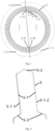
- the stator assembly comprises a stator core 1 and a multi-branch rectangular conductor winding 3.
- An even number of axially extending stator slots are provided evenly on an inner circumference of the stator core 1.
- the stator slots open radially inward, one end of the stator core slot is the insertion side, and the other end is the connection side.
- Each stator slot is divided into multiple layers for accommodating rectangular conductors.
- the stator slots are preferably divided into 6 or 8 layers.
- the multi-branch conductor winding 3 is arranged in the stator slots, and comprises B number of parallel branches, and B is an integer multiple of 4. For example, there are 4 parallel branches or 8 parallel branches.
- the number of slots per phase per pole, Q, of the stator assembly is an odd number, and Q and B satisfy a relationship that both (Q+1)*2B and (Q-1)*2B are integers, so that each branch has an integer number of rectangular conductors for each pair of magnetic poles and each layer, each of the parallel branches equally passes through each layer in the stator slots, and thus there is no phase difference of magnetic fields between the parallel branches.
- stator assembly of the present embodiment there is no phase difference of magnetic fields between the parallel branches, and each of the parallel branches equally passes through each layer in the stator slots, which fundamentally inhibits the generation of circulating current between the parallel branches, suppresses the harmonics, and improves the efficiency of the motor.
- the stator core 1 is equally divided into two regions in terms of the number of stator slots, and in different regions, the parallel branches are arranged in the stator slots in different ways.
- the windings in the stator slots of each region are connected together, there is no phase difference of magnetic fields between the parallel branches, so that there is no circulating current between the parallel branches.
- stator slots are numbered clockwise or counterclockwise as 1 to S, the 1st slot to the (S/2)-th slot are defined as the first region, and the (S/2)+1-th slot to the S-th slot are defined as the second region.
- the stator slots are numbered clockwise or counterclockwise as 1 to 72 respectively, the 1st to 36th stator slots are defined as the first region 1-1, and the 37th to 72nd stator slots are defined as the second region 1-2.
- the parallel branches are numbered in sequence with an odd number or an even number respectively.
- the parallel branches are arranged in the two regions in different ways, so that there is no phase difference of magnetic fields between the parallel branches, and the generation of circulating currents between the parallel branches is inhibited.
- the parallel branch is formed by connecting a first type of rectangular conductor coils 5 or by connecting a first type of rectangular conductor coils 5 and a second type of rectangular conductor coils 6.
- the rectangular conductor coil comprises two straight line segments, and the two straight line segments are located in two adjacent layers of two different stator slots, the rectangular conductor coil is the first type rectangular conductor coil 5; and when the rectangular conductor coil comprises one straight line segment, the rectangular conductor coil is the second type rectangular conductor coil 6.
- the first type rectangular conductor coil 5 comprises a slot inner part 5-1, a crossover part 5-2 and a welding part 5-3.
- the slot inner part 5-1 comprises a first straight line segment and a second straight line segment.
- the second type rectangular conductor coil 6 comprises a slot inner part 6-1, a lead-out terminal part 6-2, and a welding part 6-3.
- the slot inner part 5-1 is located in the stator slot.
- the crossover part 5-2 is used to connect the two straight line segments of the slot inner part 5-1 of the same first type of rectangular conductor coil 5 together.
- the welding part 5-3 is used to connect two different rectangular conductor coils by welding.
- the lead-out terminal part 6-2 is used as a lead-out terminal to connect the straight line segment of the slot inner part 6-1 of the second type of rectangular conductor coil 6 with the lead-out wire.
- the welding parts 5-3 of the first type of rectangular conductor coils 5 and the second type of rectangular conductor coils 6 have the same bending structure, which greatly reduces the difficulty of shaping the end after the rectangular conductor coils are inserted into the stator slots, and facilitates the assembling and processing of the stator assembly.
- the crossover parts 5-2 of the first type of rectangular conductor coils 5 have the same bending structure, that is, there is only one hairpin shape, which simplifies the bending mold.
- each of the parallel branches comprises a plurality of the first type of rectangular conductor coils 5 and two of the second type of rectangular conductor coils 6.
- each parallel branch comprises S*P/B/3/2-1 number of the first type of rectangular conductor coils 5 and two of the second type of rectangular conductor coils 6.
- the lead-out wire of the stator assembly is located at the end where the welding part 5-3 is, and each parallel branch only comprises a plurality of the first type of rectangular conductor coils 5. Specifically, each parallel branch only comprises S*P/ B/3/2 number of the first type of rectangular conductor coils 5, and does not comprise the second type of rectangular conductor coils 6.
- S is the number of stator slots
- P is the number of poles
- B is the number of parallel branches.
- the heads of the parallel branches are connected to each other, and the tails of the parallel branches are connected to each other to form UVW three-phase windings, and the three-phase windings are connected by star connection or delta connection.
- the star connection refers to connecting the tails of the three phases of the motor windings together, and the heads of the three phases is the power supply end, which is connected to the controller.
- the delta connection refers to connecting the tail of one phase winding to the head of the other phase winding and so on, and the three connection points are the power supply ends, which are connected to the controller.
- a non-first parallel branch in a U-phase winding of the three-phase windings is obtained by rotating a first parallel branch clockwise or counterclockwise by multiple positioning slots; and a V-phase winding and a W-phase winding are obtained by rotating the U-phase winding clockwise or counterclockwise respectively by the same multiple positioning slots.
- the present disclosure also discloses a motor, which comprises the stator assembly of any one of the above embodiments and a rotor, and the rotor is coaxially arranged inside the stator assembly.
- the motor in the present embodiment does not have a circulating current between different branches, and the energy conversion efficiency is high.
- the stator core 1 has 72 stator slots, numbered as 2-1, 2-2, ..., 2-72, and each slot is provided with 8 layers of multi-branch rectangular conductor windings 3.
- the layer closest to the rotor is defined as the first layer, and so on, the layer closest to the inside of the stator slot is defined as the eighth layer.
- the multi-branch rectangular conductor winding 3 is connected by star connection or delta connection, and the U-phase winding 3-1, the V-phase winding 3-2, and the W-phase winding 3-3 of the motor all include 4 parallel branches.
- each of a first branch 4-1 of the U-phase, a second branch 4-2 of the U-phase, a third branch 4-3 of the U-phase, and a fourth branch 4-4 of the U-phase is formed by connecting 23 first type of rectangular conductor coils 5, two second type of rectangular conductor coils 6 and a lead-out wire.
- the V-phase winding 3-2 and W-phase winding 3-3 have the same structure as the U-phase winding 3-1. That is, the multi-branch rectangular conductor winding 3 is composed of 276 first type of rectangular conductor coils 5, 24 second type of rectangular conductor coils 6 and several lead-out wires.
- each first type of rectangular conductor coil 5 is composed of three parts: a slot inner part 5-1, a crossover part 5-2, and a welding part 5-3.
- the slot inner part 5-1 comprises a first straight line segment 5-1-1 and a second straight line segment 5-1-2, which are respectively located in two adjacent layers in two different slots.
- the function of the crossover part 5-2 is to connect the first straight line segment 5-1-1 and the second straight line segment 5-1-2 together.
- the welding part 5-3 is used to connect two different rectangular conductor coils by welding.
- each second type of rectangular conductor coil 6 is also composed of three parts: a slot inner part 6-1, a lead-out terminal part 6-2 and a welding part 6-3.
- the slot inner part 6-1 comprises only one straight line segment.
- the lead-out terminal part 6-2 functions as a lead-out terminal for connecting the slot inner part 6-1 and the lead-out wire together.
- the welding part 6-3 is used to connect two different rectangular conductor coils by welding.
- the configuration of the multi-branch rectangular conductor winding 3 without a circulating current in this example is as follows.
- the stator slots of the motor are numbered clockwise as 1 to 72 respectively, the 1st to 36th stator slots are defined as the first region 1-1, and the 37th to 72nd stator slots are defined as the second region 1-2.
- the arrangement of the multi-branch conductor winding 3 in the first region 1-1 and the second region 1-2 is different. As shown in FIG.
- the slot inner part 5-1 or 6-1 of the rectangular conductor coil 5 or 6 in the first branch 4-1 of the U-phase is placed in the first layer of slots 2-1, 2-3, 2-19 and 2-21, the second layer of slots 2-10, 2-12, 2-28 and 2-30, the third layer of slots 2-2 and 2-20, the fourth layer of slots 2-11 and 2-29, the fifth layer of slots 2-2, 2-4, 2-20 and 2-22, the sixth layer of slots 2-11, 2-13, 2-29 and 2-31, the seventh layer of slots 2-3 and 2-21, and the eighth layer of slots 2-12 and 2-30.
- the slot inner part 5-1 or 6-1 of the rectangular conductor coil 5 or 6 in the first branch 4-1 of the U-phase is placed in the first layer of slots 2-38 and 2-56, the second layer of slots 2-47 and 2-65, the third layer of slots 2-37, 2-39, 2-55 and 2-57, the fourth layer of slots 2-46, 2-48, 2-64 and 2-66, the fifth layer of slots 2-39 and 2-57, the sixth layer of slots 2-48 and 2-66, the seventh layer of slots 2-38, 2-40, 2-56 and 2-58, and the eighth layer of slots 2-47, 2-49, 2-65, and 2-67.
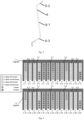
- FIG. 5 is a schematic diagram of the winding connection of the first parallel branch 4-1 of the U-phase, and the lead-out wire is located at the end where the crossover part 5-2 or 6-2 is.
- the configuration of the second branch 4-2, the third branch 4-3, and the fourth branch 4-4 of the U-phase can be obtained by rotating a certain number of slots in the following manner.
- the position of the slot inner part 5-1 or 6-1 of the rectangular conductor coil 5 or 6 in the second branch 4-2 of the U-phase is obtained by rotating clockwise by 36 slots on the basis of the first branch 4-1 of the U-phase.
- the slot inner part 5-1 or 6-1 of the rectangular conductor coil 5 or 6 is placed in the first layer of slots 2-2 and 2-20, the second layer of slots 2-11 and 2-29, the third layer of slots 2-1, 2-3, 2-19 and 2-21, the fourth layer of slots 2-10, 2-12, 2-28 and 2-30, the fifth layer of slots 2-3 and 2-21, the sixth layer of slots 2-12 and 2-30, the seventh layer of slots 2-2, 2-4, 2-20 and 2-22, and the eighth layer of slots 2-11, 2-13, 2-29, and 2-31.
- the slot inner part 5-1 or 6-1 of the rectangular conductor coil 5 or 6 is placed in the first layer of slots 2-37, 2-39, 2-55, and 2-57, the second layer of slots 2-46, 2-48, 2-64 and 2-66, the third layer of slots 2-38 and 2-56, the fourth layer of slots 2-47 and 2-65, the fifth layer of slots 2-38, 2-40, 2-56 and 2-58, the sixth layer of slots2-47, 2-49, 2-65 and 2-67, the seventh layer of slots 2-39 and 2-57, and the eighth layer of slots 2-48 and 2-66.
- the position of the slot inner part 5-1 or 6-1 of the rectangular conductor coil 5 or 6 in the third branch 4-3 of the U-phase is obtained by rotating counterclockwise by 9 slots on the basis of the first branch 4-1 of the U-phase.
- the slot inner part 5-1 or 6-1 of the rectangular conductor coil 5 or 6 in the third branch 4-3 of the U-phase is placed in the first layer of slots 2-64, 2-66, 2-10, 2-12, 2-29 and 2-47, the second layer of slots 2-1, 2-3, 2-19, 2-21, 2-38 and 2-56, the third layer of slots 2-65, 2-11, 2-28, 2-30, 2-46 and 2-48, the fourth layer of slots 2-2, 2-20, 2-37, 2-39, 2-55 and 2-57, the fifth layer of slots 2-65, 2-67, 2-11, 2-13, 2-30 and 2-48, the sixth layer of slots 2-2, 2-4, 2-20, 2-22, 2-39 and 2-57, the seventh layer of slots 2-66, 2-12, 2-29, 2-31, 2-47 and 2-49, and the eighth layer
- the position of the slot inner part 5-1 or 6-1 of the rectangular conductor coil 5 or 6 in the fourth branch 4-4 of the U-phase is obtained by rotating counterclockwise by 9 slots on the basis of the second branch 4-2 of the U-phase.
- the slot inner part 5-1 or 6-1 of the rectangular conductor coil 5 or 6 in the fourth branch 4-4 of the U-phase is placed in the first layer of slots 2-65, 2-11, 2-28, 2-30, 2-46 and 2-48, the second layer of slots 2-2, 2-20, 2-37, 2-39, 2-55 and 2-57, the third layer of slots 2-64, 2-66, 2-10, 2-12, 2-29 and 2-47, the fourth layer of slots 2-1, 2-3, 2-19, 2-21, 2-38 and 2-56; the fifth layer of slots 2-66, 2-12, 2-29, 2-31, 2-47 and 2-49, the sixth layer of slots 2-3, 2-21, 2-38, 2-40, 2-56 and 2-58, the seventh layer of slots 2-65, 2-67, 2-11, 2-13, 2-30 and 2-48, and the eighth layer of slots
- the branches 4-1, 4-2, 4-3 and 4-4 of the U-phase winding 3-1 will have the same number of conductors in each stator slot.
- the slot 2-1 there is one conductor of the first branch 4-1 of the U-phase, one conductor of the second branch 4-2 of the U-phase, one conductor of the third branch 4-3 of the U-phase, and one conductor of the fourth branch 4-4 of the U-phase.
- the slot 2-2 there are two conductors of the first branch 4-1 of the U-phase, two conductors of the second branch 4-2 of the U-phase, two conductors of the third branch 4-3 of the U-phase, and two conductors of the fourth branch 4-4 of the U-phase.
- the number of conductors of each of the branch 4-1, 4-2, 4-3, and 4-4 of the U-phase winding is also the same.
- the first layer there are six conductors of the first branch 4-1 of the U-phase, six conductors of the second branch 4-2 of the U-phase, six conductors of the third branch 4-3 of the U-phase, and six conductors of the fourth branch 4-4 of the U-phase.
- This completely symmetrical winding structure can eliminate the circulating current caused by the phase difference of magnetic fields between different branches, and improve the efficiency and reduce the noise of the motor effectively.
- the branches 4-1, 4-2, 4-3, and 4-4 of the U-phase winding 3-1 are connected head-to-head and tail-to-tail to form the U-phase winding 3-1.
- the V-phase winding 3-2 its configuration is obtained by rotating the U-phase winding 3-1 clockwise by 6 slots; for the W-phase winding 3-3, its configuration is obtained by rotating the U-phase winding 3-1 counterclockwise by 6 slots.
- Their details will not be described herein.
- the three-phase windings are connected by star connection or delta connection, and finally form a complete set of rectangular conductor windings 3 of the motor.
- the advantage of this structure is that the bending structures of the conductors of the welding parts 5-3 or 6-3 of all the rectangular conductor coils 5 or 6 are completely consistent, which can reduce the difficulty of shaping the conductor end after the rectangular conductors are inserted into the stator core.
- the Example 2 differs from the Example 1 in that, taking the U-phase winding 3-1 as an example, each of its parallel branches 4-1, 4-2, 4-3, and 4-4 is formed by connecting 24 first type of rectangular conductor coil 5 and the lead-out wire without the second type of rectangular conductor coil 6.
- the composition of the V-phase winding 3-2 and the W-phase winding 3-3 is the same as that of the U-phase winding 3-1. Therefore, the multi-branch rectangular conductor winding 3 is composed of 288 first type of rectangular conductor coils 5 and several lead-out wires.
- the first type of rectangular conductor coil 5 is composed of three parts: an inner part 5-1, a crossover part 5-2, and a welding part 5-3.
- the slot inner part 5-1 comprises a first straight line segment 5-1-1 and a second straight line segment 5-1-2, which are respectively located in two adjacent layers in two slots spaced by 9 slots.
- the function of the crossover part 5-2 is to connect the first straight line segment 5-1-1 and the second straight line segment 5-1-2 together spaced by 9 slots.
- the welding part 5-3 is used to connect two different rectangular conductor coils by welding.
- FIG. 6 is a schematic diagram of the winding connection of the first parallel branch 4-1 of the U-phase, in which the lead-out wire is located at the end where the welding part 5-3 is.
- the advantage of this structure is that the bending structure of the crossover part 5-2 of all the rectangular conductor coils 5 is completely consistent, that is, there is only one hairpin shape, which simplifies the bending mold.
- the position of the slot inner part 5-1 of the rectangular conductor coil 5 in the second branch 4-2 of the U-phase is obtained by rotating clockwise by 36 slots on the basis of the first branch 4-1 of the U-phase; the position of the slot inner part 5-1 of the rectangular conductor coil 5 in the third branch 4-3 of the U-phase is obtained by rotating counterclockwise by 9 slots on the basis of the first branch 4-1 of the U-phase, and the position of the slot inner part 5-1 of the rectangular conductor coil 5 in the fourth branch 4-4 of the U-phase is obtained by rotating counterclockwise by 9 slots on the basis of the second branch 4-2 of the U-phase.
- the branches 4-1, 4-2, 4-3, and 4-4 of the U-phase winding 3-1 are connected head-to-head and tail-to-tail to form the U-phase winding 3-1.
- the V-phase winding 3-2 its configuration is obtained by rotating the U-phase winding 3-1 clockwise by 6 slots; for the W-phase winding 3-3, its configuration is obtained by rotating the U-phase winding 3-1 counterclockwise by 6 slots.
- the three-phase windings are connected by star connection or delta connection, and finally form a complete set of rectangular conductor windings 3 of the motor.
Landscapes
- Engineering & Computer Science (AREA)
- Power Engineering (AREA)
- Windings For Motors And Generators (AREA)
Claims (7)
- Statoranordnung, wobei die Statoranordnung einen Statorkern (1) und eine mehrzweigige rechteckige Leiterwicklung (3) umfasst, wobei eine geradzahlige Anzahl von Statorschlitzen auf einem Innenumfang des Statorkerns (1) bereitgestellt ist und jeder der Statorschlitze in mehrere Schichten unterteilt ist, um rechteckige Leiter aufzunehmen, wobei die mehreren Schichten eine erste Schicht, eine zweite Schicht, eine dritte Schicht, eine vierte Schicht, eine fünfte Schicht, eine sechste Schicht, eine siebte Schicht und eine achte Schicht umfassen;wobei die mehrzweigige rechteckige Leiterwicklung (3) in den Statorschlitzen bereitgestellt ist und die mehrzweigige rechteckige Leiterwicklung (3) eine Anzahl von B parallelen Zweigen (4-1, 4-2, 4-3, 4-4) umfasst und B eine ganze Zahl ist, die ein Vielfaches von 4 ist;die Anzahl von Schlitzen pro Phase pro Pol, Q, der Statoranordnung eine ungerade Zahl ist, Q und B eine Beziehung erfüllen, in der sowohl (Q+1)*2/B als auch (Q-1)*2/B ganze Zahlen sind und jeder der parallelen Zweige (4-1, 4-2, 4-3, 4-4) gleichermaßen jede Schicht in den Statorschlitzen passiert, sodass es keine Phasendifferenz der Magnetfelder zwischen den parallelen Zweigen gibt;wobei die Statorschlitze im Uhrzeigersinn oder gegen den Uhrzeigersinn als 1 bis S nummeriert sind, der 1.Schlitz bis zum (S/2).Schlitz als erste Region (1-1) definiert sind und der (S/2)+1.Schlitz bis zum S.Schlitz als zweite Region (1-2) definiert sind;die parallelen Zweige (4-1, 4-2, 4-3, 4-4) aufeinanderfolgend mit einer ungeraden Zahl, beziehungsweise einer geraden Zahl nummeriert sind;dadurch gekennzeichnet, dass,wenn die parallelen Zweige (4-1, 4-2, 4-3, 4-4) in den Statorschlitzen angeordnet sind,in jedem Paar von Magnetpolen in der ersten Region (1-1) die parallelen Zweige (4-1, 4-3) mit einer ungeraden Zahl (Q+1)*2B-mal in jeder aus der ersten Schicht, der zweiten Schicht, der fünften Schicht und der sechsten Schicht vorkommen und (Q-1)*2B-mal in jeder aus der dritten Schicht, der vierten Schicht, der siebten Schicht und der achten Schicht vorkommen;in jedem Paar von Magnetpolen in der zweiten Region (1-2) die parallelen Zweige (4-1, 4-3) mit einer ungeraden Zahl (Q-1)*2B-mal in jeder aus der ersten Schicht, der zweiten Schicht, der fünften Schicht und der sechsten Schicht vorkommen und (Q+1)*2B-mal in jeder aus der dritten Schicht, der vierten Schicht, der siebten Schicht und der achten Schicht vorkommen;in jedem Paar von Magnetpolen in der ersten Region (1-1) die parallelen Zweige (4-2, 4-4) mit einer geraden Zahl (Q-1)*2B-mal in jeder aus der ersten Schicht, der zweiten Schicht, der fünften Schicht und der sechsten Schicht vorkommen und (Q+1)*2B-mal in jeder aus der dritten Schicht, der vierten Schicht, der siebten Schicht und der achten Schicht vorkommen; undin jedem Paar von Magnetpolen in der zweiten Region (1-2) die parallelen Zweige (4-2, 4-4) mit einer geraden Zahl (Q+1)*2B-mal in jeder aus der ersten Schicht, der zweiten Schicht, der fünften Schicht und der sechsten Schicht vorkommen und (Q-1)*2B-mal in jeder aus der dritten Schicht, der vierten Schicht, der siebten Schicht und der achten Schicht vorkommen.
- Statoranordnung nach Anspruch 1, dadurch gekennzeichnet, dass: jeder der parallelen Zweige gebildet ist, indem eine erste Art von rechteckigen Leiterspulen (5) verbunden wird oder eine erste Art von rechteckigen Leiterspulen (5) und eine zweite Art von rechteckigen Leiterspulen (6) verbunden wird;wobei die erste Art von rechteckigen Leiterspulen (5) einen Schlitzinnenteil (5-1), einen Kreuzungsteil (5-2) und einen Schweißteil (5-3) umfasst und der Schlitzinnenteil (5-1) ein erstes geradliniges Segment und ein zweites geradliniges Segment umfasst;wobei die zweite Art von rechteckigen Leiterspulen (6) einen Schlitzinnenteil (6-1), einen Ausgangsanschlussteil (6-2) und einen Schweißteil (6-3) umfasst.
- Statoranordnung nach Anspruch 2, dadurch gekennzeichnet, dass: die Schweißteile (5-3) der ersten Art von rechteckigen Leiterspulen (5) und die Schweißteile (6-3) der zweiten Art von rechteckigen Leiterspulen (6) die gleiche Biegestruktur aufweisen;
oder
die Kreuzungsteile (5-2) der ersten Art von rechteckigen Leiterspulen (5) die gleiche Biegestruktur aufweisen. - Statoranordnung nach Anspruch 2, dadurch gekennzeichnet, dass: ein Ausgangsdraht der Statoranordnung sich an dem Ende befindet, wo der Kreuzungsteil (5-2) ist, und jeder der parallelen Zweige eine Vielzahl der ersten Art von rechteckigen Leiterspulen (5) und zwei der zweiten Art von rechteckigen Leiterspulen (6) umfasst;
oder
sich ein Ausgangsdraht der Statoranordnung an dem Ende befindet, wo der Schweißteil (5-3) ist, und jeder der parallelen Zweige nur eine Vielzahl der ersten Art von rechteckigen Leiterspulen (5) umfasst. - Statoranordnung nach einem der Ansprüche 1-4, dadurch gekennzeichnet, dass:
Köpfe der parallelen Zweige miteinander verbunden sind und Schwänze der parallelen Zweige miteinander verbunden sind, um dreiphasige UVW-Wicklungen bereitzustellen, und die dreiphasigen Wicklungen durch eine Sternschaltung oder eine Dreieckschaltung verbunden sind. - Statoranordnung nach Anspruch 5, dadurch gekennzeichnet, dass: ein nicht-erster paralleler Zweig in einer U-Phasenwicklung der dreiphasigen Wicklungen durch Drehen eines ersten parallelen Zweigs im Uhrzeigersinn oder gegen den Uhrzeigersinn durch mehrere Positionierungsschlitze erhalten wird; und eine V-Phasenwicklung und eine W-Phasenwicklung durch Drehen der U-Phasenwicklung im Uhrzeigersinn bzw. gegen den Uhrzeigersinn durch die gleichen mehreren Positionierungsschlitze erhalten wird.
- Motor, dadurch gekennzeichnet, dass: der Motor eine Statoranordnung nach einem der Ansprüche 1-6 und einen Rotor umfasst, wobei der Rotor koaxial innerhalb der Statoranordnung bereitgestellt ist.
Applications Claiming Priority (1)
| Application Number | Priority Date | Filing Date | Title |
|---|---|---|---|
| CN202110172185.4A CN112821599B (zh) | 2021-02-08 | 2021-02-08 | 一种定子组件和电机 |
Publications (2)
| Publication Number | Publication Date |
|---|---|
| EP4040646A1 EP4040646A1 (de) | 2022-08-10 |
| EP4040646B1 true EP4040646B1 (de) | 2023-10-11 |
Family
ID=75863981
Family Applications (1)
| Application Number | Title | Priority Date | Filing Date |
|---|---|---|---|
| EP21205938.0A Active EP4040646B1 (de) | 2021-02-08 | 2021-11-02 | Statoranordnung und motor |
Country Status (4)
| Country | Link |
|---|---|
| US (1) | US11764630B2 (de) |
| EP (1) | EP4040646B1 (de) |
| JP (1) | JP7281568B2 (de) |
| CN (1) | CN112821599B (de) |
Families Citing this family (5)
| Publication number | Priority date | Publication date | Assignee | Title |
|---|---|---|---|---|
| CN112928836B (zh) * | 2021-01-25 | 2022-06-21 | 中国第一汽车股份有限公司 | 一种插针绕组式定子及电机 |
| CN115694023B (zh) * | 2021-07-23 | 2025-12-09 | 蔚然(南京)动力科技有限公司 | 扁线波绕线、多相电机及三相电机 |
| CN115395697B (zh) * | 2022-08-24 | 2025-11-04 | 株洲中车时代电气股份有限公司 | 一种扁线绕组、具有其的定子、电机和车辆 |
| CN117791921B (zh) * | 2022-09-09 | 2026-04-28 | 上海汽车电驱动有限公司 | 三相对称绕组排布驱动电机及车辆 |
| WO2024060038A1 (zh) * | 2022-09-20 | 2024-03-28 | 宁德时代(上海)智能科技有限公司 | 一种电机及其定子和用电装置 |
Family Cites Families (9)
| Publication number | Priority date | Publication date | Assignee | Title |
|---|---|---|---|---|
| JP5948061B2 (ja) * | 2012-01-19 | 2016-07-06 | 日立オートモティブシステムズ株式会社 | 回転電機、およびその回転電機を備えた車両 |
| JP6191450B2 (ja) * | 2013-12-26 | 2017-09-06 | アイシン精機株式会社 | 3相回転電機の波巻き巻線 |
| EP3696950B1 (de) * | 2017-12-14 | 2022-08-24 | Aisin Corporation | Stator |
| US11056943B2 (en) * | 2018-07-03 | 2021-07-06 | GM Global Technology Operations LLC | Stator assembly with electrically balanced conductor layers |
| CN211606228U (zh) * | 2019-12-30 | 2020-09-29 | 克林威孚电驱动系统(嘉兴)有限公司 | 无环流发卡电机 |
| WO2021134387A1 (zh) * | 2019-12-31 | 2021-07-08 | 上海汽车集团股份有限公司 | 定子绕组结构和包括定子绕组结构的电机 |
| CN111541330B (zh) * | 2020-05-12 | 2025-07-11 | 浙江龙芯电驱动科技有限公司 | 一种每极每相槽数为3的扁铜线绕组结构及电机 |
| CN212278005U (zh) * | 2020-05-12 | 2021-01-01 | 浙江龙芯电驱动科技有限公司 | 一种每极每相槽数为3的扁铜线绕组结构及电机 |
| CN214799068U (zh) * | 2021-02-08 | 2021-11-19 | 精进电动科技股份有限公司 | 一种定子组件和电机 |
-
2021
- 2021-02-08 CN CN202110172185.4A patent/CN112821599B/zh active Active
- 2021-10-27 US US17/512,030 patent/US11764630B2/en active Active
- 2021-11-02 EP EP21205938.0A patent/EP4040646B1/de active Active
-
2022
- 2022-02-08 JP JP2022017659A patent/JP7281568B2/ja active Active
Also Published As
| Publication number | Publication date |
|---|---|
| EP4040646A1 (de) | 2022-08-10 |
| JP2022121413A (ja) | 2022-08-19 |
| CN112821599A (zh) | 2021-05-18 |
| US11764630B2 (en) | 2023-09-19 |
| US20220255385A1 (en) | 2022-08-11 |
| JP7281568B2 (ja) | 2023-05-25 |
| CN112821599B (zh) | 2025-02-28 |
Similar Documents
| Publication | Publication Date | Title |
|---|---|---|
| EP4040646A1 (de) | Statoranordnung und motor | |
| US12149135B2 (en) | Electric motor stator and electric motor | |
| CN107565720A (zh) | 一种交流发电机的定子绕组 | |
| CN110266134B (zh) | 一种两支路相绕组、定子及电机 | |
| CN111355317A (zh) | 一种扁线定子及扁线电机 | |
| US12255510B2 (en) | Mixed-phase winding, stator, and motor | |
| CN114520560A (zh) | 一种扁线绕组结构及定子组件、扁线电机 | |
| CN114552810A (zh) | 定子组件、具有其的电机及车辆 | |
| CN111478477A (zh) | 一种电机定子及电机 | |
| US20190013710A1 (en) | Rotary Electric Machine | |
| CN111478487A (zh) | 一种电机定子及电机 | |
| CN111555505A (zh) | 一种电机定子及电机 | |
| CN111371226A (zh) | 一种电机定子及电机 | |
| CN111478480A (zh) | 一种电机定子及电机 | |
| CN113422455B (zh) | 一种错位引出式4支路定子组件及电机 | |
| CN214799068U (zh) | 一种定子组件和电机 | |
| WO2025163152A1 (en) | Electric motor stator, electric motor, transmission system and vehicle | |
| WO2022156815A1 (zh) | 插针绕组式定子及电机 | |
| CN111478479A (zh) | 一种电机定子及电机 | |
| CN212033857U (zh) | 一种电机定子及电机 | |
| CN211908498U (zh) | 一种电机定子及电机 | |
| CN211880197U (zh) | 一种电机定子及电机 | |
| CN111478485A (zh) | 一种电机定子及电机 | |
| CN212033861U (zh) | 一种电机定子及电机 | |
| CN219875246U (zh) | 扁线波绕组、定子及电机 |
Legal Events
| Date | Code | Title | Description |
|---|---|---|---|
| PUAI | Public reference made under article 153(3) epc to a published international application that has entered the european phase |
Free format text: ORIGINAL CODE: 0009012 |
|
| STAA | Information on the status of an ep patent application or granted ep patent |
Free format text: STATUS: EXAMINATION IS IN PROGRESS |
|
| 17P | Request for examination filed |
Effective date: 20211102 |
|
| AK | Designated contracting states |
Kind code of ref document: A1 Designated state(s): AL AT BE BG CH CY CZ DE DK EE ES FI FR GB GR HR HU IE IS IT LI LT LU LV MC MK MT NL NO PL PT RO RS SE SI SK SM TR |
|
| GRAP | Despatch of communication of intention to grant a patent |
Free format text: ORIGINAL CODE: EPIDOSNIGR1 |
|
| STAA | Information on the status of an ep patent application or granted ep patent |
Free format text: STATUS: GRANT OF PATENT IS INTENDED |
|
| INTG | Intention to grant announced |
Effective date: 20230523 |
|
| GRAS | Grant fee paid |
Free format text: ORIGINAL CODE: EPIDOSNIGR3 |
|
| GRAA | (expected) grant |
Free format text: ORIGINAL CODE: 0009210 |
|
| STAA | Information on the status of an ep patent application or granted ep patent |
Free format text: STATUS: THE PATENT HAS BEEN GRANTED |
|
| AK | Designated contracting states |
Kind code of ref document: B1 Designated state(s): AL AT BE BG CH CY CZ DE DK EE ES FI FR GB GR HR HU IE IS IT LI LT LU LV MC MK MT NL NO PL PT RO RS SE SI SK SM TR |
|
| REG | Reference to a national code |
Ref country code: GB Ref legal event code: FG4D |
|
| REG | Reference to a national code |
Ref country code: CH Ref legal event code: EP |
|
| REG | Reference to a national code |
Ref country code: DE Ref legal event code: R096 Ref document number: 602021005790 Country of ref document: DE |
|
| REG | Reference to a national code |
Ref country code: IE Ref legal event code: FG4D |
|
| P01 | Opt-out of the competence of the unified patent court (upc) registered |
Effective date: 20231115 |
|
| REG | Reference to a national code |
Ref country code: LT Ref legal event code: MG9D |
|
| REG | Reference to a national code |
Ref country code: NL Ref legal event code: MP Effective date: 20231011 |
|
| REG | Reference to a national code |
Ref country code: AT Ref legal event code: MK05 Ref document number: 1621220 Country of ref document: AT Kind code of ref document: T Effective date: 20231011 |
|
| PG25 | Lapsed in a contracting state [announced via postgrant information from national office to epo] |
Ref country code: NL Free format text: LAPSE BECAUSE OF FAILURE TO SUBMIT A TRANSLATION OF THE DESCRIPTION OR TO PAY THE FEE WITHIN THE PRESCRIBED TIME-LIMIT Effective date: 20231011 |
|
| PG25 | Lapsed in a contracting state [announced via postgrant information from national office to epo] |
Ref country code: GR Free format text: LAPSE BECAUSE OF FAILURE TO SUBMIT A TRANSLATION OF THE DESCRIPTION OR TO PAY THE FEE WITHIN THE PRESCRIBED TIME-LIMIT Effective date: 20240112 |
|
| PG25 | Lapsed in a contracting state [announced via postgrant information from national office to epo] |
Ref country code: IS Free format text: LAPSE BECAUSE OF FAILURE TO SUBMIT A TRANSLATION OF THE DESCRIPTION OR TO PAY THE FEE WITHIN THE PRESCRIBED TIME-LIMIT Effective date: 20240211 |
|
| PG25 | Lapsed in a contracting state [announced via postgrant information from national office to epo] |
Ref country code: LT Free format text: LAPSE BECAUSE OF FAILURE TO SUBMIT A TRANSLATION OF THE DESCRIPTION OR TO PAY THE FEE WITHIN THE PRESCRIBED TIME-LIMIT Effective date: 20231011 |
|
| PG25 | Lapsed in a contracting state [announced via postgrant information from national office to epo] |
Ref country code: AT Free format text: LAPSE BECAUSE OF FAILURE TO SUBMIT A TRANSLATION OF THE DESCRIPTION OR TO PAY THE FEE WITHIN THE PRESCRIBED TIME-LIMIT Effective date: 20231011 |
|
| PG25 | Lapsed in a contracting state [announced via postgrant information from national office to epo] |
Ref country code: ES Free format text: LAPSE BECAUSE OF FAILURE TO SUBMIT A TRANSLATION OF THE DESCRIPTION OR TO PAY THE FEE WITHIN THE PRESCRIBED TIME-LIMIT Effective date: 20231011 |
|
| PG25 | Lapsed in a contracting state [announced via postgrant information from national office to epo] |
Ref country code: LT Free format text: LAPSE BECAUSE OF FAILURE TO SUBMIT A TRANSLATION OF THE DESCRIPTION OR TO PAY THE FEE WITHIN THE PRESCRIBED TIME-LIMIT Effective date: 20231011 Ref country code: IT Free format text: LAPSE BECAUSE OF NON-PAYMENT OF DUE FEES Effective date: 20231102 Ref country code: IS Free format text: LAPSE BECAUSE OF FAILURE TO SUBMIT A TRANSLATION OF THE DESCRIPTION OR TO PAY THE FEE WITHIN THE PRESCRIBED TIME-LIMIT Effective date: 20240211 Ref country code: GR Free format text: LAPSE BECAUSE OF FAILURE TO SUBMIT A TRANSLATION OF THE DESCRIPTION OR TO PAY THE FEE WITHIN THE PRESCRIBED TIME-LIMIT Effective date: 20240112 Ref country code: ES Free format text: LAPSE BECAUSE OF FAILURE TO SUBMIT A TRANSLATION OF THE DESCRIPTION OR TO PAY THE FEE WITHIN THE PRESCRIBED TIME-LIMIT Effective date: 20231011 Ref country code: BG Free format text: LAPSE BECAUSE OF FAILURE TO SUBMIT A TRANSLATION OF THE DESCRIPTION OR TO PAY THE FEE WITHIN THE PRESCRIBED TIME-LIMIT Effective date: 20240111 Ref country code: AT Free format text: LAPSE BECAUSE OF FAILURE TO SUBMIT A TRANSLATION OF THE DESCRIPTION OR TO PAY THE FEE WITHIN THE PRESCRIBED TIME-LIMIT Effective date: 20231011 Ref country code: PT Free format text: LAPSE BECAUSE OF FAILURE TO SUBMIT A TRANSLATION OF THE DESCRIPTION OR TO PAY THE FEE WITHIN THE PRESCRIBED TIME-LIMIT Effective date: 20240212 |
|
| PG25 | Lapsed in a contracting state [announced via postgrant information from national office to epo] |
Ref country code: SE Free format text: LAPSE BECAUSE OF FAILURE TO SUBMIT A TRANSLATION OF THE DESCRIPTION OR TO PAY THE FEE WITHIN THE PRESCRIBED TIME-LIMIT Effective date: 20231011 Ref country code: RS Free format text: LAPSE BECAUSE OF FAILURE TO SUBMIT A TRANSLATION OF THE DESCRIPTION OR TO PAY THE FEE WITHIN THE PRESCRIBED TIME-LIMIT Effective date: 20231011 Ref country code: PL Free format text: LAPSE BECAUSE OF FAILURE TO SUBMIT A TRANSLATION OF THE DESCRIPTION OR TO PAY THE FEE WITHIN THE PRESCRIBED TIME-LIMIT Effective date: 20231011 Ref country code: NO Free format text: LAPSE BECAUSE OF FAILURE TO SUBMIT A TRANSLATION OF THE DESCRIPTION OR TO PAY THE FEE WITHIN THE PRESCRIBED TIME-LIMIT Effective date: 20240111 Ref country code: LV Free format text: LAPSE BECAUSE OF FAILURE TO SUBMIT A TRANSLATION OF THE DESCRIPTION OR TO PAY THE FEE WITHIN THE PRESCRIBED TIME-LIMIT Effective date: 20231011 Ref country code: HR Free format text: LAPSE BECAUSE OF FAILURE TO SUBMIT A TRANSLATION OF THE DESCRIPTION OR TO PAY THE FEE WITHIN THE PRESCRIBED TIME-LIMIT Effective date: 20231011 |
|
| PG25 | Lapsed in a contracting state [announced via postgrant information from national office to epo] |
Ref country code: DK Free format text: LAPSE BECAUSE OF FAILURE TO SUBMIT A TRANSLATION OF THE DESCRIPTION OR TO PAY THE FEE WITHIN THE PRESCRIBED TIME-LIMIT Effective date: 20231011 |
|
| REG | Reference to a national code |
Ref country code: DE Ref legal event code: R097 Ref document number: 602021005790 Country of ref document: DE |
|
| PG25 | Lapsed in a contracting state [announced via postgrant information from national office to epo] |
Ref country code: LU Free format text: LAPSE BECAUSE OF NON-PAYMENT OF DUE FEES Effective date: 20231102 |
|
| PG25 | Lapsed in a contracting state [announced via postgrant information from national office to epo] |
Ref country code: CZ Free format text: LAPSE BECAUSE OF FAILURE TO SUBMIT A TRANSLATION OF THE DESCRIPTION OR TO PAY THE FEE WITHIN THE PRESCRIBED TIME-LIMIT Effective date: 20231011 |
|
| PG25 | Lapsed in a contracting state [announced via postgrant information from national office to epo] |
Ref country code: SK Free format text: LAPSE BECAUSE OF FAILURE TO SUBMIT A TRANSLATION OF THE DESCRIPTION OR TO PAY THE FEE WITHIN THE PRESCRIBED TIME-LIMIT Effective date: 20231011 |
|
| PG25 | Lapsed in a contracting state [announced via postgrant information from national office to epo] |
Ref country code: SM Free format text: LAPSE BECAUSE OF FAILURE TO SUBMIT A TRANSLATION OF THE DESCRIPTION OR TO PAY THE FEE WITHIN THE PRESCRIBED TIME-LIMIT Effective date: 20231011 Ref country code: SK Free format text: LAPSE BECAUSE OF FAILURE TO SUBMIT A TRANSLATION OF THE DESCRIPTION OR TO PAY THE FEE WITHIN THE PRESCRIBED TIME-LIMIT Effective date: 20231011 Ref country code: RO Free format text: LAPSE BECAUSE OF FAILURE TO SUBMIT A TRANSLATION OF THE DESCRIPTION OR TO PAY THE FEE WITHIN THE PRESCRIBED TIME-LIMIT Effective date: 20231011 Ref country code: LU Free format text: LAPSE BECAUSE OF NON-PAYMENT OF DUE FEES Effective date: 20231102 Ref country code: EE Free format text: LAPSE BECAUSE OF FAILURE TO SUBMIT A TRANSLATION OF THE DESCRIPTION OR TO PAY THE FEE WITHIN THE PRESCRIBED TIME-LIMIT Effective date: 20231011 Ref country code: DK Free format text: LAPSE BECAUSE OF FAILURE TO SUBMIT A TRANSLATION OF THE DESCRIPTION OR TO PAY THE FEE WITHIN THE PRESCRIBED TIME-LIMIT Effective date: 20231011 Ref country code: CZ Free format text: LAPSE BECAUSE OF FAILURE TO SUBMIT A TRANSLATION OF THE DESCRIPTION OR TO PAY THE FEE WITHIN THE PRESCRIBED TIME-LIMIT Effective date: 20231011 |
|
| REG | Reference to a national code |
Ref country code: BE Ref legal event code: MM Effective date: 20231130 |
|
| PLBE | No opposition filed within time limit |
Free format text: ORIGINAL CODE: 0009261 |
|
| STAA | Information on the status of an ep patent application or granted ep patent |
Free format text: STATUS: NO OPPOSITION FILED WITHIN TIME LIMIT |
|
| PG25 | Lapsed in a contracting state [announced via postgrant information from national office to epo] |
Ref country code: MC Free format text: LAPSE BECAUSE OF FAILURE TO SUBMIT A TRANSLATION OF THE DESCRIPTION OR TO PAY THE FEE WITHIN THE PRESCRIBED TIME-LIMIT Effective date: 20231011 |
|
| PG25 | Lapsed in a contracting state [announced via postgrant information from national office to epo] |
Ref country code: MC Free format text: LAPSE BECAUSE OF FAILURE TO SUBMIT A TRANSLATION OF THE DESCRIPTION OR TO PAY THE FEE WITHIN THE PRESCRIBED TIME-LIMIT Effective date: 20231011 |
|
| REG | Reference to a national code |
Ref country code: IE Ref legal event code: MM4A |
|
| 26N | No opposition filed |
Effective date: 20240712 |
|
| PG25 | Lapsed in a contracting state [announced via postgrant information from national office to epo] |
Ref country code: IE Free format text: LAPSE BECAUSE OF NON-PAYMENT OF DUE FEES Effective date: 20231102 |
|
| PG25 | Lapsed in a contracting state [announced via postgrant information from national office to epo] |
Ref country code: BE Free format text: LAPSE BECAUSE OF NON-PAYMENT OF DUE FEES Effective date: 20231130 |
|
| PG25 | Lapsed in a contracting state [announced via postgrant information from national office to epo] |
Ref country code: SI Free format text: LAPSE BECAUSE OF FAILURE TO SUBMIT A TRANSLATION OF THE DESCRIPTION OR TO PAY THE FEE WITHIN THE PRESCRIBED TIME-LIMIT Effective date: 20231011 |
|
| PG25 | Lapsed in a contracting state [announced via postgrant information from national office to epo] |
Ref country code: SI Free format text: LAPSE BECAUSE OF FAILURE TO SUBMIT A TRANSLATION OF THE DESCRIPTION OR TO PAY THE FEE WITHIN THE PRESCRIBED TIME-LIMIT Effective date: 20231011 Ref country code: IE Free format text: LAPSE BECAUSE OF NON-PAYMENT OF DUE FEES Effective date: 20231102 Ref country code: BE Free format text: LAPSE BECAUSE OF NON-PAYMENT OF DUE FEES Effective date: 20231130 |
|
| PG25 | Lapsed in a contracting state [announced via postgrant information from national office to epo] |
Ref country code: IT Free format text: LAPSE BECAUSE OF NON-PAYMENT OF DUE FEES Effective date: 20231102 |
|
| PGRI | Patent reinstated in contracting state [announced from national office to epo] |
Ref country code: IT Effective date: 20231130 |
|
| PG25 | Lapsed in a contracting state [announced via postgrant information from national office to epo] |
Ref country code: IT Free format text: LAPSE BECAUSE OF NON-PAYMENT OF DUE FEES Effective date: 20231102 |
|
| PGRI | Patent reinstated in contracting state [announced from national office to epo] |
Ref country code: IT Effective date: 20231130 |
|
| REG | Reference to a national code |
Ref country code: CH Ref legal event code: PL |
|
| PG25 | Lapsed in a contracting state [announced via postgrant information from national office to epo] |
Ref country code: FI Free format text: LAPSE BECAUSE OF FAILURE TO SUBMIT A TRANSLATION OF THE DESCRIPTION OR TO PAY THE FEE WITHIN THE PRESCRIBED TIME-LIMIT Effective date: 20231011 |
|
| REG | Reference to a national code |
Ref country code: CH Ref legal event code: PL |
|
| PG25 | Lapsed in a contracting state [announced via postgrant information from national office to epo] |
Ref country code: CH Free format text: LAPSE BECAUSE OF NON-PAYMENT OF DUE FEES Effective date: 20241130 |
|
| PG25 | Lapsed in a contracting state [announced via postgrant information from national office to epo] |
Ref country code: CY Free format text: LAPSE BECAUSE OF FAILURE TO SUBMIT A TRANSLATION OF THE DESCRIPTION OR TO PAY THE FEE WITHIN THE PRESCRIBED TIME-LIMIT; INVALID AB INITIO Effective date: 20211102 |
|
| PG25 | Lapsed in a contracting state [announced via postgrant information from national office to epo] |
Ref country code: TR Free format text: LAPSE BECAUSE OF FAILURE TO SUBMIT A TRANSLATION OF THE DESCRIPTION OR TO PAY THE FEE WITHIN THE PRESCRIBED TIME-LIMIT Effective date: 20231011 |
|
| PGFP | Annual fee paid to national office [announced via postgrant information from national office to epo] |
Ref country code: DE Payment date: 20251117 Year of fee payment: 5 |
|
| PGFP | Annual fee paid to national office [announced via postgrant information from national office to epo] |
Ref country code: GB Payment date: 20251126 Year of fee payment: 5 |
|
| PGFP | Annual fee paid to national office [announced via postgrant information from national office to epo] |
Ref country code: IT Payment date: 20251107 Year of fee payment: 5 |
|
| PGFP | Annual fee paid to national office [announced via postgrant information from national office to epo] |
Ref country code: FR Payment date: 20251127 Year of fee payment: 5 |
|
| PG25 | Lapsed in a contracting state [announced via postgrant information from national office to epo] |
Ref country code: HU Free format text: LAPSE BECAUSE OF FAILURE TO SUBMIT A TRANSLATION OF THE DESCRIPTION OR TO PAY THE FEE WITHIN THE PRESCRIBED TIME-LIMIT; INVALID AB INITIO Effective date: 20211102 |