EP4040174A1 - Dispositif et procédé de diagnostic de batterie - Google Patents
Dispositif et procédé de diagnostic de batterie Download PDFInfo
- Publication number
- EP4040174A1 EP4040174A1 EP21803824.8A EP21803824A EP4040174A1 EP 4040174 A1 EP4040174 A1 EP 4040174A1 EP 21803824 A EP21803824 A EP 21803824A EP 4040174 A1 EP4040174 A1 EP 4040174A1
- Authority
- EP
- European Patent Office
- Prior art keywords
- battery
- battery cell
- error
- voltage
- cumulative
- Prior art date
- Legal status (The legal status is an assumption and is not a legal conclusion. Google has not performed a legal analysis and makes no representation as to the accuracy of the status listed.)
- Pending
Links
Images


Classifications
-
- G—PHYSICS
- G01—MEASURING; TESTING
- G01R—MEASURING ELECTRIC VARIABLES; MEASURING MAGNETIC VARIABLES
- G01R31/00—Arrangements for testing electric properties; Arrangements for locating electric faults; Arrangements for electrical testing characterised by what is being tested not provided for elsewhere
- G01R31/36—Arrangements for testing, measuring or monitoring the electrical condition of accumulators or electric batteries, e.g. capacity or state of charge [SoC]
- G01R31/382—Arrangements for monitoring battery or accumulator variables, e.g. SoC
- G01R31/3835—Arrangements for monitoring battery or accumulator variables, e.g. SoC involving only voltage measurements
-
- G—PHYSICS
- G01—MEASURING; TESTING
- G01R—MEASURING ELECTRIC VARIABLES; MEASURING MAGNETIC VARIABLES
- G01R1/00—Details of instruments or arrangements of the types included in groups G01R5/00 - G01R13/00 and G01R31/00
- G01R1/28—Provision in measuring instruments for reference values, e.g. standard voltage, standard waveform
-
- G—PHYSICS
- G01—MEASURING; TESTING
- G01R—MEASURING ELECTRIC VARIABLES; MEASURING MAGNETIC VARIABLES
- G01R17/00—Measuring arrangements involving comparison with a reference value, e.g. bridge
- G01R17/02—Arrangements in which the value to be measured is automatically compared with a reference value
-
- G—PHYSICS
- G01—MEASURING; TESTING
- G01R—MEASURING ELECTRIC VARIABLES; MEASURING MAGNETIC VARIABLES
- G01R31/00—Arrangements for testing electric properties; Arrangements for locating electric faults; Arrangements for electrical testing characterised by what is being tested not provided for elsewhere
- G01R31/36—Arrangements for testing, measuring or monitoring the electrical condition of accumulators or electric batteries, e.g. capacity or state of charge [SoC]
- G01R31/3644—Constructional arrangements
- G01R31/3648—Constructional arrangements comprising digital calculation means, e.g. for performing an algorithm
-
- G—PHYSICS
- G01—MEASURING; TESTING
- G01R—MEASURING ELECTRIC VARIABLES; MEASURING MAGNETIC VARIABLES
- G01R31/00—Arrangements for testing electric properties; Arrangements for locating electric faults; Arrangements for electrical testing characterised by what is being tested not provided for elsewhere
- G01R31/36—Arrangements for testing, measuring or monitoring the electrical condition of accumulators or electric batteries, e.g. capacity or state of charge [SoC]
- G01R31/378—Arrangements for testing, measuring or monitoring the electrical condition of accumulators or electric batteries, e.g. capacity or state of charge [SoC] specially adapted for the type of battery or accumulator
-
- G—PHYSICS
- G01—MEASURING; TESTING
- G01R—MEASURING ELECTRIC VARIABLES; MEASURING MAGNETIC VARIABLES
- G01R31/00—Arrangements for testing electric properties; Arrangements for locating electric faults; Arrangements for electrical testing characterised by what is being tested not provided for elsewhere
- G01R31/36—Arrangements for testing, measuring or monitoring the electrical condition of accumulators or electric batteries, e.g. capacity or state of charge [SoC]
- G01R31/382—Arrangements for monitoring battery or accumulator variables, e.g. SoC
-
- G—PHYSICS
- G01—MEASURING; TESTING
- G01R—MEASURING ELECTRIC VARIABLES; MEASURING MAGNETIC VARIABLES
- G01R31/00—Arrangements for testing electric properties; Arrangements for locating electric faults; Arrangements for electrical testing characterised by what is being tested not provided for elsewhere
- G01R31/36—Arrangements for testing, measuring or monitoring the electrical condition of accumulators or electric batteries, e.g. capacity or state of charge [SoC]
- G01R31/396—Acquisition or processing of data for testing or for monitoring individual cells or groups of cells within a battery
-
- H—ELECTRICITY
- H01—ELECTRIC ELEMENTS
- H01M—PROCESSES OR MEANS, e.g. BATTERIES, FOR THE DIRECT CONVERSION OF CHEMICAL ENERGY INTO ELECTRICAL ENERGY
- H01M10/00—Secondary cells; Manufacture thereof
- H01M10/42—Methods or arrangements for servicing or maintenance of secondary cells or secondary half-cells
- H01M10/48—Accumulators combined with arrangements for measuring, testing or indicating the condition of cells, e.g. the level or density of the electrolyte
-
- G—PHYSICS
- G01—MEASURING; TESTING
- G01R—MEASURING ELECTRIC VARIABLES; MEASURING MAGNETIC VARIABLES
- G01R31/00—Arrangements for testing electric properties; Arrangements for locating electric faults; Arrangements for electrical testing characterised by what is being tested not provided for elsewhere
- G01R31/36—Arrangements for testing, measuring or monitoring the electrical condition of accumulators or electric batteries, e.g. capacity or state of charge [SoC]
- G01R31/367—Software therefor, e.g. for battery testing using modelling or look-up tables
-
- H—ELECTRICITY
- H01—ELECTRIC ELEMENTS
- H01M—PROCESSES OR MEANS, e.g. BATTERIES, FOR THE DIRECT CONVERSION OF CHEMICAL ENERGY INTO ELECTRICAL ENERGY
- H01M10/00—Secondary cells; Manufacture thereof
- H01M10/42—Methods or arrangements for servicing or maintenance of secondary cells or secondary half-cells
- H01M10/425—Structural combination with electronic components, e.g. electronic circuits integrated to the outside of the casing
- H01M2010/4271—Battery management systems including electronic circuits, e.g. control of current or voltage to keep battery in healthy state, cell balancing
-
- Y—GENERAL TAGGING OF NEW TECHNOLOGICAL DEVELOPMENTS; GENERAL TAGGING OF CROSS-SECTIONAL TECHNOLOGIES SPANNING OVER SEVERAL SECTIONS OF THE IPC; TECHNICAL SUBJECTS COVERED BY FORMER USPC CROSS-REFERENCE ART COLLECTIONS [XRACs] AND DIGESTS
- Y02—TECHNOLOGIES OR APPLICATIONS FOR MITIGATION OR ADAPTATION AGAINST CLIMATE CHANGE
- Y02E—REDUCTION OF GREENHOUSE GAS [GHG] EMISSIONS, RELATED TO ENERGY GENERATION, TRANSMISSION OR DISTRIBUTION
- Y02E60/00—Enabling technologies; Technologies with a potential or indirect contribution to GHG emissions mitigation
- Y02E60/10—Energy storage using batteries
Definitions
- the present invention relates to an apparatus for diagnosing a battery, and more particularly, to an apparatus for diagnosing whether or not an error has occurred in battery cells by measuring a voltage of each of the battery cells.
- the secondary battery is a battery capable of charging and discharging, and includes all of a conventional Ni/Cd battery, Ni/MH battery, etc. and a recent lithium ion battery.
- the lithium ion battery has an advantage of having much higher energy density compared to the conventional Ni/Cd battery, Ni/MH battery, etc.
- the lithium ion battery can be manufactured in a small size and light weight, and thus the lithium ion battery is used as a power source for a mobile device.
- the lithium ion battery can be used as a power source for an electric vehicle, and thus attracts attention as a next-generation energy storage medium as its range of use has been expanded to a power source for an electric vehicle.
- the secondary battery is generally used as a battery pack including a battery module in which a plurality of battery cells are connected in series and/or in parallel.
- the state and operation of the battery pack are managed and controlled by a battery management system.
- the battery cells in the battery pack are charged by receiving power from the outside.
- Charged battery cells provide power to various devices and/or circuits connected to the battery pack. When the battery cell fails, power is not properly supplied to various devices and/or circuits, and thus a fatal accident may occur. Therefore, it is important to monitor the battery cells to diagnose whether or not an error has occurred in the battery cells. In addition, for an accurate diagnosis, a problem arises as to which diagnostic criteria and which diagnostic method to use.
- the present invention is intended to solve the technical problem described above, and an object thereof is to provide an apparatus for diagnosing a battery that determines whether or not an error has occurred in a battery cell based on a voltage tendency of battery cells and finally determines whether or not the battery cell is defective by accumulating measured values of the battery cell.
- An apparatus for diagnosing a battery may include a voltage measurement circuit, a data processing circuit, and a diagnosis circuit.
- the voltage measurement circuit may measure a voltage of a battery cell.
- the data processing circuit may calculate a target statistical value indicating a state of the battery cell based on a voltage measured by the voltage measurement circuit, and may calculate a cumulative statistical value by accumulating target statistical values of the battery cell during an analysis period.
- the diagnosis circuit may determine whether or not an error has occurred in the battery cell through a cumulative determination operation of comparing the cumulative statistical value with a cumulative reference value, and count the number of times of cumulative error when it is determined that the error has occurred in the battery cell in the cumulative determination operation.
- a method for diagnosing a battery may include a voltage measurement step of measuring, by an apparatus for diagnosing a battery, a voltage between an input terminal and an output terminal of a battery cell, a calculation step of calculating, by the apparatus for diagnosing a battery, a target statistical value indicating a state of the battery cell based on the voltage measured in the voltage measurement step, and calculating a cumulative statistical value by accumulating target statistical values of the battery cell during an analysis period, and a first diagnosis step of determining, by the apparatus for diagnosing a battery, whether or not an error has occurred in the battery cell through a cumulative determination operation of comparing the cumulative statistical value with a cumulative reference value and counting the number of times of cumulative error when it is determined that the error has occurred in the battery cell through the cumulative determination operation.
- the present invention it is possible to determine whether or not an error has occurred in a battery cell through an absolute determination, a relative determination, and a cumulative determination. According to the present invention, it is possible to more accurately determine whether or not the battery cell is defective by synthesizing the results of the absolute determination, the relative determination, and the cumulative determination.
- FIG. 1 is a block diagram illustrating a configuration of a battery control system.
- FIG. 1 a battery management system including a battery pack 1 and an upper-level controller 2 included in an upper-level system according to an embodiment of the present invention is schematically illustrated.
- the battery pack 1 includes a battery module 11 composed of one or more battery cells and capable of charging and discharging, a switching unit 14 connected in series to a positive terminal side or a negative terminal side of the battery module 11 to control a charge and discharge current flow of the battery module 11, and a battery management system 20 that monitors a voltage, current, temperature, etc. of the battery pack 1 to control and manage the battery module to prevent over-charging, over-discharging, etc.
- the switching unit 14 is a switching element for controlling a current flow for charging or discharging of the battery module 11 and, for example, a semiconductor switching element such as at least one MOSFET or a relay may be used.
- the battery management system 20 may monitor the voltage, current, temperature, etc. of the battery pack 1, and may measure the current, voltage, temperature, etc. of the battery pack using a sensor 12 provided adjacent to the semiconductor switching element 14.
- the battery management system 20 is an interface that receives values obtained by measuring various parameters described above, and may include a plurality of terminals and a circuit connected to these terminals to perform processing for input values.
- the battery management system 20 may control ON/OFF of the switching element 14, for example, a MOSFET, and may be connected to the battery module 11 to monitor a state of the battery module 11.
- the switching element 14 for example, a MOSFET
- the upper-level controller 2 may transmit a control signal for the battery module 11 to the battery management system 20. Accordingly, an operation of the battery management system 20 may be controlled based on a signal applied from the upper-level controller 2.
- the battery cell of the present invention may be configured to be included in a battery pack used in an energy storage system (ESS) or a vehicle, etc. However, the battery cell is not limited to these uses.
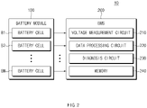
- FIG. 2 is a block diagram illustrating the configuration of the battery pack 10 including the apparatus for diagnosing a battery of the present invention.
- a battery module 100 and a battery management system 200 of FIG. 2 may correspond to the battery module 11 and the battery management system 20 of FIG. 1 .
- the battery pack 10 may include the battery module 100 and the battery management system 200.
- the "apparatus for diagnosing a battery” of the present invention may be an apparatus including some or all components of the battery management system 200.
- the "apparatus for diagnosing a battery” may include a voltage measurement circuit 210, a data processing circuit 220, a diagnosis circuit 230, and a memory 240.
- the battery module 100 may include a plurality of battery cells B1 to BN.
- the plurality of battery cells B1 to BN may be configured to be connected in series and/or in parallel.
- the battery pack 1 is illustrated as including one battery module 100, but the present invention is not limited thereto, and the battery pack 10 may include one or more battery modules.
- the battery module 100 may receive power from a power supply (not illustrated). In the charging section, voltages at both ends of each of the battery cells B1 to BN may increase. In the following descriptions, "voltage of a battery cell” means “voltage between both ends of a battery cell”.
- the battery module 100 may supply power to external devices and/or circuits. There may be a rest section between the charging section and the discharging section. In the rest section, the battery module 100 may stop an operation of receiving power or supplying power. Therefore, in an ideal case, in the rest section, the voltage of the battery module 100 is maintained constant.
- external devices and/or circuits may be a motor, a power control unit (PCU), an inverter, etc.
- an abnormal voltage drop phenomenon may be detected in the battery cell.
- the abnormal voltage drop phenomenon means that the voltage of the battery cell is abnormally decreased in the charging section, the discharging section and/or the rest section.
- the battery management system 200 of the present invention may monitor the battery cells B1 to BN to determine whether or not the abnormal voltage drop phenomenon has occurred in the battery cells B1 to BN.
- the battery management system 200 may include the voltage measurement circuit 210, the data processing circuit 220, the diagnosis circuit 230, and the memory 240.
- the battery management system 200 may more accurately determine whether or not the abnormal voltage drop phenomenon has occurred in the battery cells B1 to BN through an absolute determination operation, a relative determination operation, and a cumulative determination operation.
- checking whether or not the error has occurred in the battery cell B1 means checking whether or not the abnormal voltage drop phenomenon occurs in the battery cell B1.
- a method for inspecting, by the battery management system 200, the battery cell B1 is intensively described.
- the battery management system 200 may also inspect the remaining battery cells B2 to BN in the same manner as the method for inspecting the battery cell B1.
- the absolute determination operation performed in the charging section and the discharging section may be different from the absolute determination operation performed in the rest section.
- the absolute determination operation performed in the charging section and the discharging section is expressed as a first absolute determination operation.
- the absolute determination operation performed in the rest section is expressed as a second absolute determination operation.
- the voltage measurement circuit 210 may measure a voltage of the battery cell B1 in the charging section and the discharging section.
- the voltage measurement circuit 210 may output voltage data for the measured voltage to the data processing circuit 220.
- the data processing circuit 220 may process the voltage data received from the voltage measurement circuit 210 to calculate a first statistical value.
- the first statistical value may be a value obtained by differentiating capacitance of the battery cell B1 with respect to the voltage.
- the capacitance of the battery cell B1 may be measured by the battery management system 200. The first statistical value will be described in detail with reference to FIGS. 4 to 6f .
- the diagnosis circuit 230 may receive information about the first statistical value.
- the diagnosis circuit 230 may compare the first statistical value with a first absolute reference value.
- the first absolute reference value may be a value set by a user. However, the present invention is not limited thereto, and the first absolute reference value may be a value determined based on the state of the battery cell B1, such as the temperature of the battery cell B1 and the SOC of the battery cell B1.
- the diagnosis circuit 230 may determine that an error has occurred in the battery cell B1 when the first statistical value is equal to or greater than the first absolute reference value.
- the voltage measurement circuit 210 may measure the voltage of the battery cell B1 in the rest section.
- the voltage measurement circuit 210 may output voltage data for the measured voltage to the data processing circuit 220.
- the data processing circuit 220 may process the voltage data received from the voltage measurement circuit 210 to calculate a second statistical value.
- the second statistical value may be a value calculated by substituting the voltage data into a voltage fitting equation. The second statistical value will be described in detail with reference to FIGS. 7 to 8e .
- the diagnosis circuit 230 may receive information about the second statistical value.
- the diagnosis circuit 230 may compare the second statistical value with a second absolute reference value.
- the second absolute reference value may be a value set by the user. However, the present invention is not limited thereto, and the second absolute reference value may be a value determined based on the state of the battery cell B1, such as the temperature of the battery cell B1 and the SOC of the battery cell B1.
- the diagnosis circuit 230 may determine that an error has occurred in the battery cell B1 when the second statistical value is equal to or greater than the second absolute reference value.
- the relative determination operation performed in the charging section and the discharging section may be different from the relative determination operation performed in the rest section.
- the relative determination operation performed in the charging section and the discharging section is expressed as a first relative determination operation.
- the relative determination operation performed in the rest section is expressed as a second relative determination operation.
- the voltage measurement circuit 210 may measure the voltage of each of the battery cells B1 to BN in the charging section and the discharging section.
- the voltage measurement circuit 210 may output voltage data for the measured voltages to the data processing circuit 220.
- the data processing circuit 220 may process the voltage data received from the voltage measurement circuit 210 to calculate a first relative reference value. Specifically, the data processing circuit 220 may calculate the first statistical values of the battery cells B1 to BN in the same manner as the method of calculating the first statistical value of the battery cell B1 in the absolute determination operation. The data processing circuit 220 may determine the first relative reference value based on an 'n' sigma value of the first statistical values of the battery cells B1 to BN. Here, 'n' may be a positive number. As an example, the first relative reference value may be a +3 value of the first statistical values.
- the diagnosis circuit 230 may receive information about the first statistical value and the first relative reference value of the battery cell B1. The diagnosis circuit 230 may compare the first statistical value with the first relative reference value. The diagnosis circuit 230 may determine that an error has occurred in the battery cell B1 when the first statistical value is equal to or greater than the first relative reference value.
- the voltage measurement circuit 210 may measure the voltage of each of the battery cells B1 to BN in the rest section.
- the voltage measurement circuit 210 may output voltage data for the measured voltages to the data processing circuit 220.
- the data processing circuit 220 may process the voltage data received from the voltage measurement circuit 210 to calculate a second relative reference value. Specifically, the data processing circuit 220 may calculate the second statistical values of the battery cells B1 to BN in the same manner as the method of calculating the second statistical value of the battery cell B1 in the absolute determination operation. The data processing circuit 220 may determine the second relative reference value based on a 'k' sigma value of the second statistical values of the battery cells B1 to BN. Here, 'k' may be a positive number. As an example, the second relative reference value may be a +3 sigma value of the second statistical values.
- the diagnosis circuit 230 may receive information about the second statistical value and the second relative reference value of the battery cell B1. The diagnosis circuit 230 may compare the second statistical value with the second relative reference value. The diagnosis circuit 230 may determine that an error has occurred in the battery cell B1 when the second statistical value is equal to or greater than the second relative reference value.
- the battery management system 200 may perform the absolute determination operation and the relative determination operation in each fixed cycle during the analysis period. By using data generated in the absolute determination operation and the relative determination operation, the battery management system 200 may perform the cumulative determination operation.
- the data processing circuit 220 may calculate a cumulative statistical value by accumulating statistical values related to the voltage of the battery cell B1. For example, the data processing circuit 220 may calculate the cumulative statistical value by accumulating all statistical values calculated during the analysis period. As another example, the data processing circuit 220 may calculate the cumulative statistical value by selecting some of the statistical values calculated during the analysis period and accumulating the selected statistical values. Specifically, the data processing circuit 220 may calculate the cumulative statistical value by accumulating statistical values obtained at a specific time zone during the analysis period.
- the data processing circuit 220 may calculate the cumulative reference value by accumulating relative reference values in a similar way to the way in calculating the cumulative statistical value.
- the present invention is not limited thereto, and the data processing circuit 220 may calculate the cumulative reference value based on the absolute reference value.
- the cumulative reference value may be a value set by a user.
- the diagnosis circuit 230 may receive information about the cumulative statistical value and the cumulative reference value. The diagnosis circuit 230 may compare the cumulative statistical value with the cumulative reference value. The diagnosis circuit 230 may determine that an error has occurred in the battery cell B1 when the cumulative statistical value is equal to or greater than the cumulative reference value.
- the cumulative determination operation means a determination operation of performing a comparison operation using values (e.g., cumulative statistical value, cumulative reference value) obtained by accumulating and adding data values (e.g., statistical value, relative reference value) for the relative determination operation during a specific period, or performing a comparison operation using values (e.g., cumulative statistical value, cumulative reference value) obtained by accumulating and adding data values (e.g., statistical value, relative reference value) for the absolute determination operation during a specific period.
- values e.g., cumulative statistical value, cumulative reference value
- data values e.g., statistical value, relative reference value
- the data processing circuit 220 and the diagnosis circuit 230 may perform a first cumulative determination operation by accumulating the first statistical value of the battery cell B1, or perform a second cumulative determination operation by accumulating the second statistical value of the battery cell B1.
- the present invention is not limited thereto, and the data processing circuit 220 and the diagnosis circuit 230 may perform both the first cumulative determination operation and the second cumulative determination operation.
- the diagnosis circuit 230 may repeatedly perform the absolute determination operation, the relative determination operation, and the cumulative determination operation.
- the diagnosis circuit 230 may count the number of times of absolute error in which it is determined that an error has occurred in the battery cell B1 in the absolute determination operation.
- the diagnosis circuit 230 may count the number of times of relative error in which it is determined that the error has occurred in the battery cell B1 in the relative determination operation.
- the diagnosis circuit 230 may count the number of times of cumulative error in which it is determined that the error has occurred in the battery cell B1 in the cumulative determination operation.
- the diagnosis circuit 230 may finally determine whether or not the battery cell B1 is defective based on the number of times of absolute error, the number of times of relative error, and the number of times of cumulative error. For example, the diagnosis circuit 230 may determine that the battery cell B1 is defective when the number of times of absolute error, the number of times of relative error, and the number of times of cumulative error of the battery cell B1 are equal to or greater than the first number of times, the second number of times, and the third number of times, respectively.
- the first number of times, the second number of times, and the third number of times may be values set by the user.
- the first number of times, the second number of times, and the third number of times may be determined based on the number of times of absolute error, the number of times of relative error, and the number of times of cumulative error of the battery cells B1 to BN, respectively.
- the first number of times may be the number of times of absolute error corresponding to the top 2% among the number of times of absolute error of the battery cells B1 to BN.
- the memory 240 may store data necessary for the absolute determination operation, the relative determination operation, and the cumulative determination operation.
- the memory 240 may store data generated by the data processing circuit 220 and the diagnosis circuit 230.
- the memory 240 may store data relating to the statistical value, the cumulative statistical value, the number of times of absolute error, the number of times of relative error, and the number of times of cumulative error.
- the memory 240 may store information about the battery cell B1, information about a defect occurring in the battery cell B1, etc.
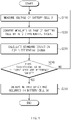
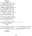
- FIG. 3 is a flowchart for describing the operation of the battery management system of FIG. 2 .
- the fact that the battery management system 200 performs the absolute determination operation means that it performs the first absolute determination operation and/or the second absolute determination operation.
- the fact that the battery management system 200 performs the relative determination operation means that it performs the first relative determination operation and/or the second relative determination operation.
- the fact that the battery management system 200 performs the cumulative determination operation means that it performs the first cumulative determination operation and/or the second cumulative determination operation.
- the battery management system 200 may measure the voltage of each of the battery cells B1 to BN.
- the battery management system 200 may generate data for the absolute determination operation, the relative determination operation, and the cumulative determination operation based on the measured voltages. Specifically, the battery management system 200 may calculate the statistical value, the cumulative statistical value, etc. of the battery cell B1 based on the measured voltages, and may calculate the relative reference value, the cumulative reference value, etc.
- the battery management system 200 may perform the absolute determination operation.
- the battery management system 200 may compare the statistical value of the battery cell B1 with the absolute reference value. When the statistical value of the battery cell B1 is equal to or greater than the absolute reference value, the battery management system 200 may increase the number of times of absolute error by one.
- the battery management system 200 may perform the relative determination operation.
- the battery management system 200 may compare the statistical value of the battery cell B1 with the relative reference value. When the statistical value of the battery cell B1 is equal to or greater than the relative reference value, the battery management system 200 may increase the number of times of relative error by one.
- the battery management system 200 may perform the cumulative determination operation.
- the battery management system 200 may compare the cumulative statistical value of the battery cell B1 with the relative reference value. When the accumulated statistical value of the battery cell B1 is equal to or greater than the cumulative reference value, the battery management system 200 may increase the number of times of cumulative error by one.
- the battery management system 200 may determine whether or not the number of times of absolute error, the number of times of relative error, and the number of times of cumulative error satisfy a condition.
- the condition may be to determine whether or not the number of times of absolute error, the number of times of relative error, and the number of accumulated errors are equal to or greater than the first number of times, the second number of times, and the third number of times, respectively. Satisfying the condition may mean that the numbers of errors (the number of times of absolute error, the number of times of relative error, and the number of accumulated errors) should be respectively equal to or greater than the corresponding numbers of times (the first number of times, the second number of times, and the third number of times), but is not limited thereto.
- Satisfying the condition may be sufficient when at least one of (e.g., the number of times of cumulative error) the numbers of errors is equal to or greater than the corresponding number of times (the third number of times).
- satisfying the condition may mean that the sum of some of the numbers of errors (e.g. the sum of the number of times of absolute error and the number of times of relative error) is equal to or greater than the sum of the corresponding numbers of times (sum of the first number of times and the second number of times), and the remainder of the numbers of errors (the number of times of cumulative error) among the numbers of errors is equal to or greater than the corresponding number of times (the third number of times).
- the condition may be variously modified from comparing the numbers of errors with the corresponding numbers of times.
- operation S170 When the number of times of absolute error, the number of times of relative error, and the number of times of cumulative error satisfy the above conditions, operation S170 is performed. In operation S170, the battery management system 200 may finally determine that the battery cell B1 is defective.
- operation S180 When the number of times of absolute error, the number of times of relative error, and the number of times of cumulative error do not satisfy the above condition, operation S180 is performed. In operation S180, the battery management system 200 may finally determine that the battery cell B1 is not defective.
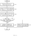
- FIG. 4 is a flowchart for describing the first absolute determination operation of the battery management system of FIG. 2 .
- the battery management system 200 of FIG. 2 may perform the first absolute determination operation in the charging section and the discharging section.
- the voltage measurement circuit 210 may measure the voltage of the battery cell B1.
- the data processing circuit 220 may convert the voltage of the battery cell B1 measured by the voltage measurement circuit 210 into a differential signal.
- the data processing circuit 220 may calculate a differential signal (e.g., dQ/dV) with respect to the capacitance and voltage of the battery cell B1.
- the battery management system 200 may measure the capacitance of the battery cell B1.
- the data processing circuit 220 may convert the voltage of the battery cell B1 into a differential signal for a region in which the voltage is 4V to 4.2V. This is because unstable voltage profile due to internal short-circuit inside the battery can be detected in a high voltage region where the voltage of the battery cell B1 is 4V to 4.2V and the influence differential peak change due to other factors such as deviation or degradation between battery cells (B1) can be excluded.
- the differential signal converted by the data processing circuit 220 according to an embodiment of the present invention is not necessarily limited to a voltage range of 4V to 4.2V, and in addition, it may be converted into a differential signal with respect to any voltage range.
- the data processing circuit 220 may perform preprocessing on voltage data of the battery cell B1 before calculating the differential signal, thereby converting the voltage of the battery cell B1 to be differentiable in a predetermined section.
- the preprocessing operation of the data processing circuit 220 will be described in detail with reference to FIG. 5 .
- the data processing circuit 220 may calculate the first statistical value with respect to the converted differential signal.
- the first statistical value of the differential signal calculated by the data processing circuit 220 is for determining abnormal behavior of the battery in a sliding window (or moving window) method, as will be described later.
- the first statistical value for the differential signal may include a standard deviation.
- the diagnosis circuit 230 may diagnose the battery cell B1 based on the differential signal converted by the data processing circuit 220.
- operation S250 When the first statistical value with respect to the differential signal of the battery voltage is equal to or greater than the first absolute reference value, operation S250 is performed.
- the diagnosis circuit 230 may determine that an error has occurred in the battery cell B1.
- the diagnosis circuit 230 may diagnose the battery cell B1 in the sliding window method with respect to the first statistical value of the differential signal relating to the battery voltage. As described above, when the diagnosis circuit 230 diagnoses the battery cell B1 in the sliding window method, the size of the window may be arbitrarily set by the user.
- operations S210 to S540 are performed again.
- FIG. 5 is a flowchart for describing the data preprocessing operation of the data processing circuit of FIG. 2 .
- the data processing circuit 220 of FIG. 2 may perform the data preprocessing operation to calculate the first statistical value.
- the voltage measurement circuit 210 may measure the voltage of the battery cell B1.
- the data processing circuit 220 may perform preprocessing on voltage data of the battery cell B1 before calculating the differential signal, thereby converting the voltage of the battery cell B1 to be differentiable in a predetermined section. In general, there may occur cases in which differential analysis of measured voltage data of the battery is impossible due to redundant signals, discontinuous sections, etc. Accordingly, the data processing circuit 220 may perform preprocessing the voltage data of the battery cell B1 before the conversion of the differential signal, thereby converting the voltage of the battery cell B1 to be differentiable in the predetermined section.
- the data processing circuit 220 may convert the voltage of the battery cell B1 into data in the form of monotonically increasing or monotonically decreasing through sampling of the voltage data.
- the data processing circuit 220 may perform voltage sampling by classifying capacitance values of the battery cells B1 having the same voltage magnitude and calculating an average value of the capacitance values of the battery cells B1 for each voltage magnitude.
- the data processing circuit 220 may convert to satisfy continuity between adjacent data through the smoothing spline. Through this, a curve of the slope of the voltage data of the battery cell B1 may be converted into a gentle form.
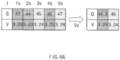
- FIG. 6a is a diagram illustrating a method of performing sampling to remove redundant signals of the battery voltage data.
- measured data of voltage and capacitance of the battery for each time are illustrated.
- the voltage is the same as 3.23V in the sections in which the battery capacitances are 43 Ah, 44 Ah, and 46 Ah, and the voltage is the same as 3.24V in the sections in which the battery capacitances are 45 Ah and 47 Ah. Accordingly, a redundant signal of voltage data may be generated, making differential analysis impossible.
- the battery voltage data may be sampled by classifying the capacitance values of the battery for the capacitance and voltage data of the battery based on a voltage of a specific magnitude, and calculating the average value thereof.
- the average value of capacitance values corresponding to each voltage may be calculated based on 3.23 V and 3.24 V, which are overlapping battery voltages.
- the voltage is 3.23 V
- 44.3Ah which is the average value of the battery capacitances 43 Ah, 44 Ah, and 46 Ah
- the voltage is 3.24V
- 46 Ah which is the average value of the battery capacitances 45 Ah and 47 Ah
- the apparatus for diagnosing a battery may convert the voltage data into the monotonically increasing (or monotonically decreasing) form based on the measured voltage by performing sampling through the method illustrated in FIG. 6a .
- FIG. 6b is a graph illustrating the results of performing preprocessing on the battery voltage data through sampling and a smoothing spline
- FIG. 6c is a graph illustrating the differential profile of the battery voltage data for each preprocessing step.
- the horizontal axis of FIG. 6b represents capacitance (Ah) of the battery
- the vertical axis represents measured voltage (V) of the battery.
- the horizontal axis of FIG. 6c represents voltage (V) of the battery
- the vertical axis represents differential signal (Ah/V) relating to the capacitance and voltage of the battery.
- the slope of the sampled voltage data can be prevented from changing rapidly and converted into a continuous curve.
- the curve becomes smoother.
- the ⁇ values may be 0.001(V) and 0.01(Q), respectively.
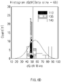
- FIG. 6d illustrates a histogram of differential signals for each charging cycle of the battery
- FIG. 6e illustrates a standard deviation for each charging cycle of the battery.
- the horizontal axis of FIG. 6d represents bins of differential signal values
- the vertical axis represents the number of each differential signal value.
- the horizontal axis of FIG. 6d represents the voltage (V)
- the vertical axis represents the standard deviation of the differential signal.
- FIG. 6d a histogram of differential signals for a case where the number of charge cycles are 113, 135, and 140, respectively is illustrated. As illustrated in FIG. 6d , it can be seen that, when the charging cycle is 113, a normal charging profile is illustrated, but when the charging cycle is 135 and 140, it can be confirmed that an unstable open profile appears.
- the apparatus for diagnosing a battery it is possible to quantify a determination condition of normal behavior or abnormal behavior of the battery voltage.
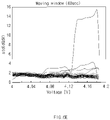
- FIG. 6f is a diagram illustratively describing an example of diagnosing an abnormality in the battery through the standard deviation of the differential signal in the apparatus for diagnosing a battery according to an embodiment of the present invention.
- FIG. 6f illustrates the result derived by setting the size of the moving (sliding) window to 10, the horizontal axis represents the voltage (V), and the vertical axis represents the standard deviation of the differential signal.
- the apparatus for diagnosing a battery may diagnose an abnormal voltage drop due to an internal short-circuit of the battery based on whether or not the standard deviation of the differential signal is equal to or greater than a preset reference value. For example, referring to FIG. 6f , it may be determined that the abnormal voltage drop occurs in a region where the battery voltage is 4.16 to 4.18 V.
- the standard deviation of the differential signal of the battery voltage is used to determine whether or not it is normal, but the present invention is not limited thereto, and in addition to the standard deviation, various statistical values such as an average value, a median value, extraversion, and kurtosis for a differential signal may be used.
- FIG. 7 is a flowchart for describing the second absolute determination operation of the battery management system of FIG. 2 .
- the voltage measurement circuit 210 may measure the voltage of the battery cell B1. In this case, the voltage measurement circuit 210 may measure the voltage of the battery cell B1 at predetermined time intervals.
- the data processing circuit 220 may calculate a fitting equation for the voltage of the battery cell B1.
- the fitting equation calculated by the data processing circuit 220 may be a model voltage representing a voltage profile of the battery cell B1.
- the fitting equation may be an exponential equation.
- the data processing circuit 220 may calculate the fitting equation by least square estimation. However, this is only an example, and the present invention is not limited thereto, and the data processing circuit 220 may calculate the fitting equation in various ways.
- the data processing circuit 220 may calculate the fitting equation for a voltage in a rest section in which the voltage drop phenomenon occurs due to an internal short-circuit of the battery occurs after charging of the battery cell B1 is completed.
- the second statistical value may be calculated based on the fitting equation for the voltage of the battery cell B1 calculated by the data processing circuit 220.
- the second statistical value may be a difference value between the measured voltage of the battery cell B1 and a voltage according to the fitting equation calculated by the data processing circuit 220.
- the diagnosis circuit 230 may diagnose whether or not an error has occurred in the battery cell B1 based on the fitting equation for the voltage of the battery cell B1 calculated by the data processing circuit 220.
- operation S440 is performed.
- the second absolute reference value may be set based on a predetermined measurement error value of the voltage measurement circuit 210.
- the diagnosis circuit 230 may determine that the error has occurred in the battery cell B1.
- operations S410 to S430 are performed again.
- FIG. 8a is a diagram illustrating a voltage change when the voltage drop due to the internal short-circuit of the battery cell occurs over the entire section
- FIG. 8b is a diagram illustrating a voltage change when the voltage drop due to the internal short-circuit of the battery cell temporarily occurs.
- the horizontal axis represents the time (seconds)
- the vertical axis represents the voltage (V) of the battery.
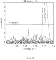
- FIG. 8c is a graph illustrating an actual rest voltage for about 10 minutes after charging the battery, a voltage according to a fitting equation, and a difference value therebetween.
- the horizontal axis of FIG. 8c represents the time (seconds)
- the vertical axis (left) represents the voltage (V) of the battery
- the vertical axis (right) represents the absolute value (mV) of the difference between the actual measured voltage of the battery and the voltage according to the fitting equation.
- the fitting equation of the battery voltage in FIG. 8c is derived through the least square estimation.
- the fitting equation of the battery voltage may be completed by calculating constants of a, b, and c in the above equation, respectively.
- the above equation is only illustrated as an example, the present invention is not limited thereto, and various equations capable of making the voltage of the battery fit may be used.
- the absolute value of the difference between the actual measured rest voltage (raw) of the battery and the voltage (Exp.fitting) according to the fitting equation is indicated by
- the absolute value of the difference between the actual measured voltage of the battery and the voltage according to the fitting equation means the second statistical value.
- the apparatus for diagnosing the battery of the present invention may detect the voltage drop due to the internal short-circuit in the rest section of the battery by comparing the second statistical value with the second absolute reference value.
- FIG. 8d illustrates a result of detecting, by the apparatus for diagnosing a battery according to an embodiment of the present invention, that the voltage drop due to the internal short-circuit of the battery cell occurs over the entire section
- FIG. 8e illustrates a result of detecting, by the apparatus for diagnosing a battery according to an embodiment of the present invention, that the voltage drop due to the internal short-circuit of the battery cell temporarily occurs.
- the horizontal axes of FIGS. 8d and 8e represent the number of charging cycles of the battery, and the vertical axes thereof represent the maximum value (V) of the difference value between the actual measured voltage of the battery and the voltage according to the fitting equation.
- the apparatus for diagnosing a battery may compare the second statistical value with a second absolute reference value when the voltage drop due to the internal short-circuit of the battery cell occurs over the entire section, and may determine that the voltage drop due to the internal short-circuit of the battery has occurred when the second statistical value is equal to or greater than the second absolute reference value.
- the apparatus for diagnosing a battery may compare the second statistical value with the second absolute reference value even when the voltage drop due to the internal short-circuit of the battery cell temporarily occurs, and may determine that the voltage drop due to the internal short-circuit of the battery has occurred when the second statistical value is equal to or greater than the second absolute reference value.
- the reference values of FIGS. 8d and 8e may be determined based on a measurement range of the voltage sensor itself.
- FIG. 9 is a flowchart for describing the relative determination operation of the battery management system of FIG. 2 .
- the first relative determination operation and the second relative determination operation may be performed.
- the voltage measurement circuit 210 may measure the voltage of each of the battery cells B1 to BN. In this case, the voltage measurement circuit 210 may measure the voltages of the battery cells B1 to BN at predetermined time intervals.
- the data processing circuit 220 may calculate the statistical value of the battery cell B1 based on the measured voltage of the battery cell B1.
- the statistical value is an index value indicating a voltage state of the battery cell B1 and may be calculated in various ways.
- the data processing circuit 220 may calculate a standard deviation for the differential signal of the voltage of the battery cell B1.
- the data processing circuit 220 may calculate the standard deviation of the differential signal of the voltage of the battery cell B1 in each time section.
- the first statistical value may be the maximum value among the calculated standard deviations.
- the data processing circuit 220 may calculate the statistical values of the battery cells B1 to BN based on the measured voltages of the battery cells B1 to BN.
- the statistical values of the battery cells B1 to BN may also be calculated substantially the same manner as described with reference to operation S520.
- the data processing circuit 220 may calculate a relative reference value based on the statistical values of the battery cells B1 to BN.
- the relative reference value may be an 'n' sigma value of the statistical values of the battery cells B1 to BN.
- 'n' may be a positive number.
- the diagnosis circuit 230 may compare the statistical value of the battery cell B1 with the relative reference value.
- operation S560 When the statistical value of the battery cell B1 is greater than or equal to the relative reference value, operation S560 is performed. In operation S560, the diagnosis circuit 230 may determine that an error has occurred in the battery cell B1. When the statistical value of the battery cell B1 is less than the relative reference value, operation S570 is performed. In operation S570, the diagnosis circuit 230 may determine that the error has not occurred in the battery cell B1
- FIG. 10a is a graph illustrating the distribution of first statistical values of battery cells.
- the horizontal axis of FIG. 10a represents the first statistical value, and the vertical axis represents the number of battery cells.
- the first statistical value of any battery cell described with reference to FIG. 10a means the maximum value (max(std(dQ/dV))) among standard deviations of values obtained by differentiating the voltage of the battery cell.
- the relative reference value is determined to be a 3 sigma value of statistical values of the battery cells B1 to BN, it may be determined that an error has occurred in battery cells included on the right side of the 3-sigma value in the graph of FIG. 10a .
- FIG. 10b is a graph illustrating the number of times of relative error of battery cells.
- the horizontal axis of FIG. 10b represents the number of times of relative error of the battery cells, and the vertical axis represents the number of battery cells.
- the diagnosis circuit 230 may perform the relative determination operation at predetermined time intervals.
- the diagnosis circuit 230 may accumulate the number of times of relative error of the battery cells while performing the relative determination operation. The greater the number of times of relative error of the battery cell, the higher the probability that the battery cell is determined to be defective.
- FIG. 11 is a flowchart for describing the cumulative determination operation of the battery management system of FIG. 2 .
- the first cumulative determination operation and the second cumulative determination operation may be performed.
- the voltage measurement circuit 210 may measure the voltage of the battery cell B1 at predetermined time intervals.
- the data processing circuit 220 may calculate the statistical values of the battery cell B1 based on the voltages of the battery cell B1 measured at predetermined time intervals.
- the data processing circuit 220 may calculate a cumulative statistical value by accumulating the statistical values of the battery cell B1.
- the data processing circuit 220 may select some of the statistical values calculated during the analysis period, and may calculate the cumulative statistical value by accumulating the selected statistical values.
- the diagnosis circuit 230 may compare the cumulative statistical value with the cumulative reference value.
- the cumulative reference value may be a value calculated by accumulating the relative reference values, a value set by a user, or a value set based on the state of the battery cell.
- operation S650 When the cumulative statistical value is equal to or greater than the cumulative reference value, operation S650 is performed. In operation S650, the diagnosis circuit 230 may determine that an error has occurred in the battery cell B1. When the cumulative statistical value is less than the cumulative reference value, operation S660 is performed. In operation S660, the diagnosis circuit 230 may determine that the error has not occurred in the battery cell B1.
- the apparatus for diagnosing a battery of the present invention can finally determine whether or not the battery cell is defective by comprehensively considering the results of the absolute determination operation, the relative determination operation, and the cumulative determination operation. Accordingly, according to the present invention, accuracy of determining a defect in a battery cell may be increased.
- the operation of diagnosing an error of the battery cell occurring in the charging section and the discharging section and the operation of diagnosing the error of the battery cell occurring in the rest section may be performed, and the diagnostic operations described above may be selectively performed according to a situation.
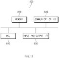
- FIG. 12 is a diagram illustrating a hardware configuration of the apparatus for diagnosing a battery according to an embodiment of the present invention.
- the apparatus for diagnosing a battery 800 includes a microcontroller (MCU) 810 for controlling various processes and each configuration, a memory 820 in which an operating system program and various programs (e.g., a battery diagnosis program, a voltage approximation calculation program, etc.) are recorded, an input/output interface 830 that provides an input interface and an output interface between the battery cell module and/or the semiconductor switching element, and a communication interface 840 capable of communicating with the outside through a wired or wireless communication network.
- the computer program according to the present invention may be implemented as a module, that performs, for example, each of the functional blocks illustrated in FIG. 2 , by being recorded in the memory 820 and processed by the microcontroller 810.
- the matters described above are specific embodiments for embodying the present invention.
- the present invention will include not only the embodiments described above, but also embodiments to which simple design change is made or which are easily changeable.
- the present invention will include techniques that can be easily modified and embodied using the embodiments. Therefore, the scope of the present invention should not be limited to the embodiments described above, but should be defined by the claims described below as well as the claims and equivalents of the present invention.
Applications Claiming Priority (2)
| Application Number | Priority Date | Filing Date | Title |
|---|---|---|---|
| KR1020200058588A KR102630834B1 (ko) | 2020-05-15 | 2020-05-15 | 배터리를 진단하기 위한 장치 및 그 방법 |
| PCT/KR2021/005917 WO2021230642A1 (fr) | 2020-05-15 | 2021-05-12 | Dispositif et procédé de diagnostic de batterie |
Publications (2)
| Publication Number | Publication Date |
|---|---|
| EP4040174A1 true EP4040174A1 (fr) | 2022-08-10 |
| EP4040174A4 EP4040174A4 (fr) | 2023-10-11 |
Family
ID=78524647
Family Applications (1)
| Application Number | Title | Priority Date | Filing Date |
|---|---|---|---|
| EP21803824.8A Pending EP4040174A4 (fr) | 2020-05-15 | 2021-05-12 | Dispositif et procédé de diagnostic de batterie |
Country Status (7)
| Country | Link |
|---|---|
| US (1) | US11959969B2 (fr) |
| EP (1) | EP4040174A4 (fr) |
| JP (1) | JP7313762B2 (fr) |
| KR (1) | KR102630834B1 (fr) |
| CN (1) | CN114585939A (fr) |
| AU (1) | AU2021270154A1 (fr) |
| WO (1) | WO2021230642A1 (fr) |
Families Citing this family (2)
| Publication number | Priority date | Publication date | Assignee | Title |
|---|---|---|---|---|
| KR20230018643A (ko) | 2021-07-30 | 2023-02-07 | 주식회사 엘지에너지솔루션 | 결함 있는 배터리 셀의 검출 방법 및 그 방법을 제공하는 배터리 관리 시스템 |
| KR20230096736A (ko) * | 2021-12-23 | 2023-06-30 | 주식회사 엘지에너지솔루션 | 배터리 관리 장치 및 이의 동작 방법 |
Family Cites Families (37)
| Publication number | Priority date | Publication date | Assignee | Title |
|---|---|---|---|---|
| JP4009416B2 (ja) * | 1999-10-25 | 2007-11-14 | 松下電器産業株式会社 | 組電池制御装置 |
| JP2004247319A (ja) * | 2004-04-26 | 2004-09-02 | Ngk Insulators Ltd | 電池故障検出方法 |
| JP5301657B2 (ja) * | 2009-03-27 | 2013-09-25 | 株式会社日立製作所 | 蓄電装置 |
| JP5302086B2 (ja) | 2009-04-27 | 2013-10-02 | ホーチキ株式会社 | 警報器 |
| JP5515524B2 (ja) * | 2009-09-01 | 2014-06-11 | 日産自動車株式会社 | 二次電池の劣化状態判別システム、および二次電池の劣化状態判別方法 |
| WO2011077540A1 (fr) | 2009-12-25 | 2011-06-30 | トヨタ自動車株式会社 | Dispositif de détection d'anomalie pour batterie assemblée |
| KR101210523B1 (ko) | 2009-12-30 | 2012-12-10 | 주식회사 뉴피에스 | 충, 방전모듈로 구성된 배터리 성능향상과 상태를 진단하고 표시하는 장치 |
| JP5337908B2 (ja) | 2010-03-01 | 2013-11-06 | トヨタ自動車株式会社 | 燃料電池システム、燃料電池の制御方法、および、燃料電池の判定方法 |
| KR101182431B1 (ko) | 2010-10-12 | 2012-09-12 | 삼성에스디아이 주식회사 | 배터리 팩, 이의 제어방법 및 이를 포함하는 전력 저장 시스템 |
| KR101189342B1 (ko) | 2010-11-10 | 2012-10-09 | 기아자동차주식회사 | 차량 진단 서비스 제공 시스템 및 그 서비스 제공 방법 |
| US9037426B2 (en) * | 2011-05-13 | 2015-05-19 | GM Global Technology Operations LLC | Systems and methods for determining cell capacity values in a multi-cell battery |
| JP2013064649A (ja) | 2011-09-16 | 2013-04-11 | Toshiba Corp | 電池システムの故障検出システム |
| JP5994240B2 (ja) | 2011-12-02 | 2016-09-21 | 日産自動車株式会社 | 組電池の制御装置 |
| KR101899839B1 (ko) | 2011-12-29 | 2018-09-20 | 한국단자공업 주식회사 | 배터리 셀의 불량 검출방법 |
| JP5992186B2 (ja) * | 2012-03-16 | 2016-09-14 | 株式会社東芝 | 二次電池装置および二次電池装置の異常検出方法 |
| JP2013254664A (ja) | 2012-06-07 | 2013-12-19 | Hitachi Vehicle Energy Ltd | 二次電池の制御装置 |
| GB201216127D0 (en) * | 2012-09-11 | 2012-10-24 | Jaguar Cars | A method for determining the change in a vehicle battery |
| US20150349387A1 (en) | 2013-02-26 | 2015-12-03 | Hitachi, Ltd. | Power source device |
| JP2015031674A (ja) * | 2013-08-07 | 2015-02-16 | 株式会社東芝 | 蓄電池状態監視装置及び蓄電池装置 |
| KR101354081B1 (ko) | 2013-10-30 | 2014-01-24 | 부영주 | 배터리상태진단장치 및 그 방법 |
| KR102151048B1 (ko) * | 2014-05-19 | 2020-09-02 | 에스케이이노베이션 주식회사 | 배터리의 과충전 감지 기준 전압값 결정 장치 및 방법 |
| JP6471463B2 (ja) | 2014-11-06 | 2019-02-20 | 日立化成株式会社 | 蓄電池状態監視システム、蓄電池状態監視方法、および蓄電池状態監視プログラム |
| JP6463371B2 (ja) * | 2014-11-07 | 2019-01-30 | 株式会社日立製作所 | 蓄電管理システム |
| JP6675775B2 (ja) | 2015-08-26 | 2020-04-01 | 東北電力株式会社 | 太陽電池劣化異常判定システム |
| JP6635743B2 (ja) | 2015-10-09 | 2020-01-29 | 株式会社ピューズ | 蓄電池保全装置、及び、蓄電池保全方法 |
| KR102035675B1 (ko) | 2015-12-28 | 2019-10-23 | 주식회사 엘지화학 | 무선통신을 활용한 불량 배터리 처리 시스템 및 방법 |
| US10493848B2 (en) | 2016-01-28 | 2019-12-03 | Panasonic Intellectual Property Management Co., Ltd. | Management device and power storage system |
| KR101862454B1 (ko) * | 2016-03-02 | 2018-05-29 | 최범진 | 배터리 열화 탐지 장치 및 방법 |
| JP2017156268A (ja) | 2016-03-03 | 2017-09-07 | 株式会社東芝 | 電池ユニットおよび電流測定器の故障検出方法 |
| US9840161B2 (en) * | 2016-03-10 | 2017-12-12 | Ford Global Technologies, Llc | Circuit and method for detection of battery cell degradation events |
| KR101667913B1 (ko) | 2016-03-25 | 2016-10-20 | (주)아이비티 | 충전특성곡선을 이용한 배터리 팩 균등 충전 장치 및 방법 |
| JP6807017B2 (ja) | 2016-09-16 | 2021-01-06 | 日本電気株式会社 | 検出装置、検出方法、蓄電システムおよびプログラム |
| KR101865402B1 (ko) | 2017-03-30 | 2018-07-13 | (주)에코파워텍 | 배터리 상태 판단장치 |
| KR102259382B1 (ko) * | 2017-12-15 | 2021-06-01 | 주식회사 엘지에너지솔루션 | 배터리 누전을 검출하기 위한 방법 및 장치 |
| KR102443429B1 (ko) * | 2017-12-19 | 2022-09-14 | 주식회사 엘지에너지솔루션 | 저전압 배터리 셀 분별 장치 및 방법 |
| KR102062813B1 (ko) | 2018-08-22 | 2020-01-06 | 이용현 | 배터리군을 이루는 각 배터리셀의 soh 판별시스템 |
| KR20200027326A (ko) | 2018-09-04 | 2020-03-12 | 주식회사 엘지화학 | 배터리의 고장을 진단하기 위한 장치 및 방법과, 상기 장치를 포함하는 배터리팩 |
-
2020
- 2020-05-15 KR KR1020200058588A patent/KR102630834B1/ko active IP Right Grant
-
2021
- 2021-05-12 EP EP21803824.8A patent/EP4040174A4/fr active Pending
- 2021-05-12 CN CN202180006014.2A patent/CN114585939A/zh active Pending
- 2021-05-12 JP JP2022521016A patent/JP7313762B2/ja active Active
- 2021-05-12 US US17/773,900 patent/US11959969B2/en active Active
- 2021-05-12 WO PCT/KR2021/005917 patent/WO2021230642A1/fr unknown
- 2021-05-12 AU AU2021270154A patent/AU2021270154A1/en active Pending
Also Published As
| Publication number | Publication date |
|---|---|
| AU2021270154A1 (en) | 2022-05-26 |
| WO2021230642A1 (fr) | 2021-11-18 |
| CN114585939A (zh) | 2022-06-03 |
| JP2022551451A (ja) | 2022-12-09 |
| KR20210141212A (ko) | 2021-11-23 |
| US20220390521A1 (en) | 2022-12-08 |
| EP4040174A4 (fr) | 2023-10-11 |
| JP7313762B2 (ja) | 2023-07-25 |
| US11959969B2 (en) | 2024-04-16 |
| KR102630834B1 (ko) | 2024-01-30 |
Similar Documents
| Publication | Publication Date | Title |
|---|---|---|
| JP5349810B2 (ja) | 蓄電装置の異常検出装置及び方法並びにプログラム | |
| CN111551860B (zh) | 一种基于弛豫电压特征的电池内短路诊断方法 | |
| EP3992648A1 (fr) | Dispositif et procédé de diagnostic de batterie | |
| EP4040174A1 (fr) | Dispositif et procédé de diagnostic de batterie | |
| US11768251B2 (en) | Battery diagnosis apparatus, battery diagnosis method, battery pack, and vehicle | |
| CN114503392A (zh) | 涉及多个电池的判定装置、蓄电系统、判定方法和判定程序 | |
| US20240027540A1 (en) | Battery Cell Diagnosing Apparatus and Method | |
| EP4024066A1 (fr) | Dispositif de diagnostic de batterie, et procédé associé | |
| US20230324463A1 (en) | Method and Apparatus for Operating a System for Detecting an Anomaly of an Electrical Energy Store for a Device by Means of Machine Learning Methods | |
| JP7416982B2 (ja) | バッテリーを診断するための装置及びその方法 | |
| EP4134686A1 (fr) | Dispositif et procédé de diagnostic d'anomalie de batterie | |
| KR20230161377A (ko) | 배터리 진단 장치, 배터리 진단 방법, 배터리 팩 및 자동차 | |
| CN113811781A (zh) | 电池诊断装置和方法 | |
| Singha et al. | Impact of Kalman Filtering in Battery Management Systems |
Legal Events
| Date | Code | Title | Description |
|---|---|---|---|
| STAA | Information on the status of an ep patent application or granted ep patent |
Free format text: STATUS: THE INTERNATIONAL PUBLICATION HAS BEEN MADE |
|
| PUAI | Public reference made under article 153(3) epc to a published international application that has entered the european phase |
Free format text: ORIGINAL CODE: 0009012 |
|
| STAA | Information on the status of an ep patent application or granted ep patent |
Free format text: STATUS: REQUEST FOR EXAMINATION WAS MADE |
|
| 17P | Request for examination filed |
Effective date: 20220503 |
|
| AK | Designated contracting states |
Kind code of ref document: A1 Designated state(s): AL AT BE BG CH CY CZ DE DK EE ES FI FR GB GR HR HU IE IS IT LI LT LU LV MC MK MT NL NO PL PT RO RS SE SI SK SM TR |
|
| DAV | Request for validation of the european patent (deleted) | ||
| DAX | Request for extension of the european patent (deleted) | ||
| A4 | Supplementary search report drawn up and despatched |
Effective date: 20230912 |
|
| RIC1 | Information provided on ipc code assigned before grant |
Ipc: H01M 10/42 20060101ALI20230906BHEP Ipc: H01M 10/48 20060101ALI20230906BHEP Ipc: G01R 31/396 20190101ALI20230906BHEP Ipc: G01R 31/3835 20190101ALI20230906BHEP Ipc: G01R 31/36 20200101ALI20230906BHEP Ipc: G01R 31/367 20190101AFI20230906BHEP |