EP4040173B1 - Verfahren zum einschätzen eines betriebszustands eines elektrischen schaltgeräts und elektrisches schaltgerät zur umsetzung dieses verfahrens - Google Patents
Verfahren zum einschätzen eines betriebszustands eines elektrischen schaltgeräts und elektrisches schaltgerät zur umsetzung dieses verfahrens Download PDFInfo
- Publication number
- EP4040173B1 EP4040173B1 EP22155195.5A EP22155195A EP4040173B1 EP 4040173 B1 EP4040173 B1 EP 4040173B1 EP 22155195 A EP22155195 A EP 22155195A EP 4040173 B1 EP4040173 B1 EP 4040173B1
- Authority
- EP
- European Patent Office
- Prior art keywords
- bob
- coil
- current
- coil current
- value
- Prior art date
- Legal status (The legal status is an assumption and is not a legal conclusion. Google has not performed a legal analysis and makes no representation as to the accuracy of the status listed.)
- Active
Links
Images




Classifications
-
- G—PHYSICS
- G01—MEASURING; TESTING
- G01R—MEASURING ELECTRIC VARIABLES; MEASURING MAGNETIC VARIABLES
- G01R31/00—Arrangements for testing electric properties; Arrangements for locating electric faults; Arrangements for electrical testing characterised by what is being tested not provided for elsewhere
- G01R31/327—Testing of circuit interrupters, switches or circuit-breakers
- G01R31/3277—Testing of circuit interrupters, switches or circuit-breakers of low voltage devices, e.g. domestic or industrial devices, such as motor protections, relays, rotation switches
- G01R31/3278—Testing of circuit interrupters, switches or circuit-breakers of low voltage devices, e.g. domestic or industrial devices, such as motor protections, relays, rotation switches of relays, solenoids or reed switches
-
- G—PHYSICS
- G01—MEASURING; TESTING
- G01R—MEASURING ELECTRIC VARIABLES; MEASURING MAGNETIC VARIABLES
- G01R31/00—Arrangements for testing electric properties; Arrangements for locating electric faults; Arrangements for electrical testing characterised by what is being tested not provided for elsewhere
- G01R31/327—Testing of circuit interrupters, switches or circuit-breakers
-
- G—PHYSICS
- G01—MEASURING; TESTING
- G01R—MEASURING ELECTRIC VARIABLES; MEASURING MAGNETIC VARIABLES
- G01R19/00—Arrangements for measuring currents or voltages or for indicating presence or sign thereof
- G01R19/0092—Measuring current only
-
- H—ELECTRICITY
- H01—ELECTRIC ELEMENTS
- H01H—ELECTRIC SWITCHES; RELAYS; SELECTORS; EMERGENCY PROTECTIVE DEVICES
- H01H47/00—Circuit arrangements not adapted to a particular application of the relay and designed to obtain desired operating characteristics or to provide energising current
- H01H47/22—Circuit arrangements not adapted to a particular application of the relay and designed to obtain desired operating characteristics or to provide energising current for supplying energising current for relay coil
-
- H—ELECTRICITY
- H01—ELECTRIC ELEMENTS
- H01H—ELECTRIC SWITCHES; RELAYS; SELECTORS; EMERGENCY PROTECTIVE DEVICES
- H01H50/00—Details of electromagnetic relays
- H01H50/44—Magnetic coils or windings
-
- H—ELECTRICITY
- H01—ELECTRIC ELEMENTS
- H01H—ELECTRIC SWITCHES; RELAYS; SELECTORS; EMERGENCY PROTECTIVE DEVICES
- H01H50/00—Details of electromagnetic relays
- H01H50/54—Contact arrangements
Definitions
- the present invention relates to a method for estimating an operating state of an electrical switching device and an electrical switching device for implementing such a method.
- the invention relates more particularly to electrical contactors.
- Such electrical switching devices comprise an electromagnetic actuator comprising a fixed coil and a movable core and are configured to switch between an open state and a closed state, for example to control the power supply of an electrical load.
- the electrical contacts comprise fixed contacts and movable contacts, the latter being connected to the movable core which moves under the effect of a magnetic field created by the coil when it is traversed by an adequate electric current.
- the contactor wears out due to various factors. For example, electrical contacts wear out due to electric arcs created when the electrical contacts open, and friction within the mechanism increases due to the accumulation of dust and/or particles related to the wear of the parts, which degrades the performance of the actuator.
- Integrating a position sensor into the electromagnetic actuator to directly measure the displacement or position of the moving parts of the actuator and deduce a state of the contactor, is often not an appropriate solution, because using a sensor makes the actuator more expensive and more complex to manufacture, and it is not always possible to integrate a sensor into a contactor.
- WO-03/054895-A1 describes a diagnostic method based on a measurement of the travel time of the moving core of the electromagnetic actuator during the closing phase. Such a diagnostic method is applicable only when the core is in motion and is therefore not usable during other operating phases of the actuator.
- US-6 249 418-B1 describes methods of controlling the force and/or motion of an electromagnetic actuator, e.g. a coil, while the actuator is in motion.
- an electromagnetic actuator e.g. a coil
- US-2019/074148-A1 , US-2009/138212 And JP-2006 004902-1 each describe a switching device comprising an electromagnetic actuator, with a coil and a movable core, and a metal armature incorporating magnetic flux sensors, for example Hall effect sensors. These sensors measure magnetic fluxes passing through this armature. While the actuator is in motion, magnetic fluxes, different from the coil flux, are calculated, to evaluate states of the electromagnetic actuator, in particular a speed of movement of the movable core.
- the invention aims to address more specifically by proposing a diagnostic method that is more precise.
- the magnetic flux variations are evaluated even when the core is stationary. Since the magnetic flux value is different depending on whether the moving core of the electromagnetic actuator is in the open or closed position, the magnetic flux measurement makes it possible to evaluate the state of the actuator without requiring the addition of an additional sensor, which allows a more precise diagnosis of the state of the switching device.
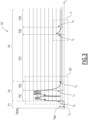
- a contactor 1 is shown on the figure 1 .
- the contactor 1 is an example of an electrical switching device intended to control the supply of electrical energy from an electrical energy source to an electrical load 23.
- the electrical energy source is not drawn to simplify the figures.
- the energy source is for example an electrical power supply network, while the electrical load 23 is for example an electric motor, which it is desired to control by means of the contactor 1.
- the contactor 1 is generally housed in a housing, represented here by a dotted rectangle.
- the contactor 1 is configured to be coupled, on the one hand, to an upstream electrical conductor 20 connected to an electrical energy source and, on the other hand, to a downstream line 22 connected to the electrical load 23.
- the contactor 1 When the contactor 1 allows the electric current to pass and the electrical load 23 is supplied with energy, the contactor 1 is in a so-called “closed” state, while when the contactor 1 prevents the passage of electrical energy to the electrical load, the contactor 1 is in a so-called “open” state.
- the electrical conductor 20 and the downstream line 22 comprise the same number of phases.
- the electrical conductors 20 and the downstream line 22, which each comprise conductive members insulated from each other, have as many conductive members as each other, each conductive member of the downstream line 22 being associated with a respective member of the upstream electrical conductor 20.
- the contactor 1 is configured to interrupt, or pass, the electric current jointly in each of the phases.
- the upstream electrical conductor 20 is three-phase.
- the conductive members here are conductive wires. Only one of the conductive wires of the electrical conductor 20, referenced 201, is shown in the figure 1 . Only the conductive wire of the power line 22 associated with the conductor 201 is shown, this conductive wire of the power line 22 being referenced 221. As a non-limiting variant, the conductive members are rigid buses.
- the contactor 1 comprises movable contacts 24, arranged on a movable bar 26, and fixed contacts 28, linked respectively to the conductors upstream 20 and downstream 22.
- Each of the movable 24 and fixed 28 contacts comprises contact pads 29, made here of metal, preferably of silver alloy or any equivalent material.
- the movable bar 26 is movable between a closed position, in which the movable contacts 24 are electrically connected to the fixed contacts 28 and electrical energy can flow through the movable bar 26 from the upstream electrical conductor 20 to the downstream line 22, and an open position, in which the movable contacts 24 are spaced from the fixed contacts 28.
- the contactor 1 When the movable bar 26 is in the closed position, the contactor 1 is in the closed state, while when the bar 26 is in the open position, the contactor 1 is in the open state.
- the transition from the open state to the closed state is a closing phase of the contactor 1, while the transition from the closed state to the open state is an opening phase of the contactor 1.
- the contact pads 29 wear out, for example under the action of electric arcs during opening, or by tearing of material caused by microwelding. This loss of material results in the thickness of the contact pads 29 being reduced throughout the life of the contactor 1, which increases the amplitude of the movement of the bar 26 during the opening or closing phases.
- the contactor 1 comprises a mechanism 290, schematically represented by a spring on the figure 1 , which is connected to the bar 26 and which makes it possible to maintain the fixed 28 and mobile 24 contacts in electrical contact with sufficient contact pressure.
- the movable bar 26 is controlled by an electromagnetic actuator 30, which comprises a control electromagnet with a coil 32, a core 34 linked to the movable bar 26 and a return member 36, for example a spring or equivalent.
- the coil 32 is configured to generate a magnetic field when it is supplied with a control electric current, in order to set the core 34, and therefore the movable bar 26, in motion.
- the electromagnetic actuator 30 is here a linear actuator, which has a variable reluctance Rel , depending in particular on the position of the core 34.
- the movements of the core 34 between the open and closed positions are represented by a double arrow F34.
- the movable contacts 24 and the associated fixed contacts 28 together form separable contacts, which are associated with the electrical conductor 20 and which are moved between an open position and a closed position by the electromagnetic actuator 30, which comprises a coil 32 and a movable core 34 linked to the separable contacts.
- the contactor 1 is shown in an intermediate configuration between the stable open and closed states of the contactor 1, in which the fixed contacts 28 and movable contacts 24 are electrically connected, but the core 34 is not in abutment in the closed position.
- the mechanism 290 allows an overtravel E of the core 34 between the moment when the fixed contacts 28 come into contact with the movable contacts 24, and the moment when the electromagnetic actuator 30 is in the stable closed position.
- the electromagnetic actuator 30 is controlled via a power supply circuit 38, itself controlled by an electronic control device 40.
- the coil 32 is thus connected to the electronic control device 40.
- the electronic control device 40 comprises a logical calculation unit - also called CPU in English - such as a programmable microcontroller or a microprocessor or equivalent, and a computer memory forming a data recording medium readable by computer.
- a logical calculation unit - also called CPU in English - such as a programmable microcontroller or a microprocessor or equivalent
- a computer memory forming a data recording medium readable by computer.
- the memory is a ROM memory, or a RAM memory, or a non-volatile memory of the EPROM or Flash type or the like.
- the memory comprises executable instructions and/or computer code to ensure the operation of the control device 40 in accordance with one or more of the embodiments described below when executed by the computational logic unit.
- the electronic control device 40 may comprise a signal processing processor (DSP), or a reprogrammable logic component (FPGA), or a specialized integrated circuit (ASIC), or any equivalent element.
- DSP signal processing processor
- FPGA reprogrammable logic component
- ASIC specialized integrated circuit
- the electronic control device 40 is itself connected to a power supply rail 42 and comprises an interface 44 configured to receive, from a user, orders to open or close the contactor 1.
- the electronic control device 40 is here represented as being integrated into the contactor 1.
- the control device 40 is remote, that is to say that it is not integrated into the same housing as the electromagnetic actuator 30.
- the power supply rail 42 is intended to supply energy to the electronic control device 40 as well as to the power supply circuit 38.
- the power supply rail 42 has a direct or alternating electrical voltage.
- the method described here is suitable for a power supply rail 42 having an alternating or direct voltage, the amplitude of which is typically between 24 V and 500 V.
- the voltage of the power supply rail 42 is an alternating voltage at 50 Hz, at 230 V.
- the interface 44 is represented here by control electrodes.
- an electrical control voltage can be applied between the control electrodes command.
- the interface 44 includes wireless communication means.
- the contactor 1 also comprises current sensors 46, configured to measure a current flowing in each of the phases of the upstream line 20, in other words a current flowing in each of the conductive wires 201 of the upstream line 20.
- the current sensors 46 and the electronic control device 40 are integrated in a housing separate from the contactor 1.
- a return member 36 represented here by a spring, exerts a return force which opposes the attractive force of the electromagnet.
- a coil current I BOB is defined as an excitation current flowing through the coil 32.
- a take-off current I D is defined as a threshold of the coil current I BOB which, when the actuator 30 is in the open state, allows the actuator 30 to move to the closed state, as soon as the coil current I BOB increases beyond the take-off current I D .
- a stall current I S - or " stall current " in English - is defined as being a threshold of the coil current I BOB which, when the actuator 30 is in the closed state, allows the actuator 30 to move to the open state, as soon as the coil current I BOB decreases below the stall current I S .
- the actuator 30 when the actuator 30 is in the open state, as long as the coil current I BOB remains below the take-off current I D , the movable core 34 is pushed back into the open position by the return member 36 of the actuator 30 and the contactor 1 remains in the open state. If the coil current I BOB increases beyond the take-off current I D , the electromagnetic force of the coil 32 becomes greater than the return force of the member 36 and the core 34 then moves from its open position to its closed position. Such a situation corresponds to a closing phase of the contactor 1.
- the contactor 1 remains in the closed state. If, while the contactor 1 is in the closed state, the coil current I BOB decreases below the dropout current I S , the electromagnetic force of the coil 32 becomes weaker than the return force of the member 36 and the mechanism 290, the core 34 is then pushed from its closed position to its open position under the effect of the return member 36 and the mechanism 290. Such a situation corresponds to an opening phase of the contactor 1.
- the take-off current I D is greater, in absolute value, than the stall current I S .
- the values of the take-off currents I D and stall current I S are adjusted during the design of the actuator 30, in particular by acting on the properties of the coil 32 or on the return forces of the member 36 and the mechanism 290.
- FIG. 2 An exemplary embodiment of the power supply circuit 38 is shown schematically in the figure 2
- the architecture of the power supply circuit 38 is not limiting, and other implementations of the various components of the power supply circuit 38 are possible, or even other electrical or electronic components may be used to perform the same functions.
- the power supply circuit 38 preferably comprises a measuring circuit 50, delimited by a dotted frame, configured to measure the value of the electrical voltage between the power supply rail 42 and an electrical ground GND of the power supply circuit 38.
- the measuring circuit 50 comprises two resistors R1 and R2 connected in series with a diode Dt between the power supply rail 42 and the electrical ground GND.
- a first measuring point here placed between the resistors R1 and R2, makes it possible to collect a first measuring voltage V1 representative of the electrical voltage present between the power supply rail 42 and the electrical ground GND.
- the electrical voltage present between the rail 42 and the ground GND being connected to the coil voltage U BOB , by extension the measuring circuit 50 is an example of a sensor configured to measure the coil voltage U BOB .
- the power supply circuit 38 includes a control circuit 51, which includes the coil 32.
- a diode D1 may be placed on the power supply rail 42 between the control circuit 51 and the measuring circuit 50 to prevent any current return to the latter.
- the diodes D1 and Dt are preferably of the same type.
- the control circuit 51 is shown here in a so-called “drop-in” configuration, which is detailed later in this description.
- the control circuit 51 comprises a power supply terminal 52, which is connected to the power supply rail 42.
- the coil 32 comprises two terminals 54 and 56. A measurement of the electrical voltage between the terminals 54 and 56 thus makes it possible to measure a coil voltage, denoted U BOB .
- Terminal 54 is connected to ground GND via a so-called “drop-out” switch T1.
- a so-called “shunt” resistor Rsh is connected in series with the drop-out switch T1 to collect a second measurement voltage V2 representative of the electric current flowing through the coil 32, in other words representative of the coil current I BOB .
- the resistor shunt Rsh is connected between dropout switch T1 and ground GND.
- Resistor Rsh is an example of a sensor configured to measure the intensity of the coil current I BOB flowing in coil 32.
- Terminal 56 is, on the one hand, connected to terminal 52 via a power switch T2 and, on the other hand, connected to ground GND via a diode, called the "freewheel" diode Drl.
- the freewheel diode Drl has a blocking direction oriented towards terminal 56.
- the switches T1 and T2 are switches controlled by a control signal from the electronic control device 40.
- the electronic control device 40 is configured to control states of the control circuit 51.
- the switches T1 and T2 are semiconductor power switches, such as Mosfet transistors, or thyristors, or insulated gate bipolar transistors (IGBTs), or any other equivalent device.
- semiconductor power switches such as Mosfet transistors, or thyristors, or insulated gate bipolar transistors (IGBTs), or any other equivalent device.
- the control circuit 51 comprises a “drop-off” device Dz, produced here by means of a Zener diode and connected in parallel to the drop-off switch T1.
- a “drop-off” device Dz produced here by means of a Zener diode and connected in parallel to the drop-off switch T1.
- the coil 32 has a coil resistance denoted R BOB and a coil inductance denoted L BOB .
- the resistance R BOB and the inductance L BOB depend, in particular, on the geometry of the coil 32, the materials used, the temperature, etc. In both embodiments of the method, the inductance L BOB is measured, as explained later in this description. In the first embodiment of the method, the coil resistance R BOB is measured, while in the second embodiment of the invention, the coil resistance R BOB is considered to be known, as explained later.
- FIG. 3 represents a graph 58 illustrating the evolution of the coil current I BOB flowing in the coil 32 over the time t during different successive operating phases of the contactor 1, denoted P1, P2 and P3, in the case where the contactor is switched from the open state to the closed state.
- Phase P1 is an initial phase, during which contactor 1 is in the open state in a stable manner, i.e. the coil current I BOB does not exceed the current take-off I D .
- the coil current I BOB remains zero during the initial phase P1.
- Phase P2 corresponds to a closing phase, after a closing order has been received by the contactor 1.
- Phase P2 begins when the electronic control device 40 receives, at a time t 0 , a closing order via the interface 44.
- the electronic control device 40 is configured to apply the control coil voltage U BOB to the terminals of the coil 32. For example, the control device 40 then controls the drop-out switch T1 and the power supply switch T2, so as to regulate the coil voltage U BOB as a function of the voltage of the power supply rail 42.
- the voltage of the rail 42 is alternating: it is clear that the coil 32 could not operate by being connected directly to the power supply rail 42.
- the control device 40 controls the closing and opening of the power supply switch T2, in other words controls the switching of the power supply switch T2 to chop the voltage of the power supply rail 42, so that the coil voltage U BOB and the coil current I BOB are stable and adapted to the operation of the coil 32.
- the control device 40 controls the switching of the power switch T2 at a chopping frequency chosen so as not to generate noise audible to humans, for example a chopping frequency lower than 100 Hz or higher than 20 kHz.
- a chopping frequency lower than 100 Hz or higher than 20 kHz.
- the chopping frequency is generally between 20 kHz and 100 kHz. In the illustrated example, the chopping frequency is stable and equal to 20 kHz.
- the power switch T2 is closed for a fraction of this chopping cycle, defining a duty cycle ⁇ .
- the duty cycle ⁇ is a parameter varying continuously between 0 and 1, with terminals 0 and 1 included. In other words, during the same chopping cycle, the power switch T2 is open for a fraction of the cycle equal to 1- ⁇ .
- the control device 40 thus determines the duty cycle ⁇ as a function of the difference between a setpoint and a measurement of the coil current I BOB .
- the closing phase P2 comprises a dynamic phase P21, during which the coil voltage U BOB is controlled by the electronic control device 40.
- the duty cycle ⁇ is not always zero, and the coil 32 is supplied with electrical energy from the power supply rail 42.
- the coil current I BOB initially zero, then increases to exceed the take-off current I D : from this moment, the core 34 begins to move from its open position to its closed position. The core 34 then reaches the mechanical stop.
- the coil current I BOB exhibits significant variations, in particular in connection with the self-induction phenomena of the coil 32, while the movable core 34 moves within the coil 32.
- the contactor 1 is in the stable closed state.
- the dynamic phase P21 ends at a time t 1 and is followed by a transition phase P22, during which the coil current I BOB is lowered to a holding current I MN , the holding current I MN being strictly greater than the dropout current I S , such that the contactor 1 always remains in the closed state.
- the transition phase P22 ends at a time t 2 .
- the P22 transition phase lasts about 40 ms.
- the control circuit 51 is in a so-called “freewheel” mode.
- freewheel mode the coil 32 is not supplied with electrical energy by the power supply rail 42, and the coil voltage U BOB is passively imposed by the control circuit 51.
- the coil voltage U BOB is imposed by the electronic components of the control circuit 51.
- the coil current I BOB decreases freely, the electrical energy being mainly dissipated by the coil resistance R BOB .
- the coil voltage U BOB in freewheel mode, can be evaluated without requiring a measurement.
- the coil voltage U BOB in freewheel mode the coil voltage U BOB is imposed by a threshold voltage of the freewheel diode Drl.
- phase P3 At the end of the transition phase P22, the coil current I BOB is equal to the holding current I MN .
- the control device 40 adjusts the duty cycle ⁇ to a non-zero value: phase P3 then begins.
- Phase P3 corresponds to a holding phase, during which the coil current I BOB is maintained above the dropout current I S .
- the holding phase P3 here comprises a first stable portion P31, which begins at time t2 and during which the coil current I BOB is stable, thanks to the regulation of the control device 40.
- the ratio cyclic ⁇ is substantially constant.
- the first portion P31 is followed by a second portion P32, during which the coil current I BOB has a current peak, with an increasing portion, followed by a decreasing portion during which the control circuit 51 is in the freewheel mode.
- the second portion P32 corresponds to a test phase, which is detailed later.
- the test phase P32 begins at a time t 3 , ends at a time t 4 and is followed by a third portion P33, similar to the first stable portion P31, during which the coil current I BOB is stable.
- the coil resistance R BOB It is therefore recommended, for the accuracy of the calculation, to evaluate the coil resistance R BOB .
- a nominal value is chosen for the coil resistance R BOB , corresponding to a value of the coil resistance R BOB at room temperature, for example at 25°C.
- the nominal value of the coil resistance R BOB is for example measured during the manufacture of the actuator 30, or is a value given in the specifications of the manufacturer of the coil 32.
- the time interval ⁇ t has a duration between 0.01 ms and 10 ms, preferably between 0.1 ms and 1 ms, in particular equal to 0.2 ms.
- the calculation of the coil inductance L BOB is repeated several times, during several successive time intervals ⁇ t , during the same freewheeling phase.
- the time intervals ⁇ t are for example consecutive.
- An average value, noted L BOB the coil inductance L BOB during this freewheeling phase is then calculated.
- the value of the coil inductance L BOB is averaged over at least ten time intervals ⁇ t , preferably over at least twenty time intervals ⁇ t.
- the electromagnetic actuator 30 comprises a magnetic circuit made of a material.
- the movable core 34 is in particular part of the magnetic circuit of the electromagnetic actuator 30.
- the magnetic permeability of this material approaches the magnetic permeability of air. Consequently, the degree of certainty on the distinction between the open state or the closed state of the electromagnetic actuator 30, evaluated from the coil inductance measurements L BOB , decreases.
- the magnetic saturation of the material is a function of the magnetic field generated by the coil 32, in other words a function of parameters fixed by construction, such as the geometry of the coil 32, the materials used, the number of turns N, etc., and a function of the coil current I BOB .
- the coil inductance L BOB is advantageously calculated from measurements of the coil current I BOB carried out in a domain of the coil current I BOB where the material of the magnetic circuit has a magnetic saturation less than 80% of a maximum magnetic saturation of this material, preferably less than 50%.
- the magnetic core 34 is made of iron and has a magnetic saturation of the order of 2 T - Tesla -.
- the coil inductance measurements L BOB are thus carried out for a magnetic saturation of less than 1.6 T, preferably less than 1 T.
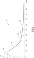
- FIG 4 represents a graph 60 illustrating this saturation phenomenon for a specific coil 32.
- Graph 60 illustrates, in freewheel mode, the evolution of the coil inductance L BOB of the coil 32, as a function of a number of Ampere-turns N ⁇ I BOB , equal to the product of the coil current I BOB multiplied by the number of turns N of the coil 32.
- the maximum value of Ampere-turns N ⁇ I BOB is representative of a magnetic saturation of the coil 32.
- figure 4 serves to illustrate the definition of a preferred domain of implementation of the estimation method according to the invention, also the inductance measurements L BOB are carried out here by means of a specific sensor, which is not necessary for the implementation of the invention.
- a first curve 602 illustrates the evolution of the coil inductance L BOB when the electromagnetic actuator 30 is open, in other words when the core 34 is in a stable open position.
- the curve 602 has a maximum 604 for a number of ampere-turns N ⁇ I BOB between 0 and 100, followed by a decreasing portion 606 with a steep slope between 100 and 250, then a decreasing portion 608 with a gentler slope beyond 250.
- a second curve 610 illustrates a measurement of the coil inductance L BOB when the electromagnetic actuator 30 is closed, in other words when the core 34 is in a stable closed position.
- the curve 610 is substantially constant, whatever the number of ampere-turns N ⁇ I BOB
- the coil inductance L BOB is calculated from the measured coil current values for which the value of a number of ampere-turns N ⁇ I BOB , equal to the product of the coil current by the number of turns N of the coil 32, is less than 500.
- the curves 602 and 604 are well separated, in other words an evaluation of the coil inductance L BOB makes it possible to distinguish, with sufficient confidence, whether the electromagnetic actuator 30 is in the open or closed state.
- the confidence is even greater when the number of Ampere-turns N ⁇ I BOB is less than 250, or even less than 100.
- FIG. 5 represents a graph 70 illustrating the implementation of the method described above during the maintenance phase P3, more precisely during the test phase P32.
- a curve 72 represents the evolution of the coil current I BOB over time.
- the control device 40 adjusts the duty cycle ⁇ so that the coil current I BOB is equal to the holding current I MN .
- the duty cycle ⁇ is generally constant, and equal to a holding value ⁇ MN .
- the coil current U BOB is also constant.
- the control device 40 adjusts the duty cycle ⁇ so that the coil current I BOB increases to a maximum value, denoted I MAX , which is reached at a instant t 5 .
- Instants t 3 and t 5 therefore delimit an increasing portion P321 of the coil current I BOB .
- the closer the duty cycle ⁇ is to ⁇ MN while being strictly greater than ⁇ MN , the more slowly the coil current I BOB increases during the increasing portion P321.
- the control device 40 puts the control device 30 in freewheel mode, that is to say that the power switch T2 remains open, the duty cycle ⁇ being equal to zero.
- the coil current I BOB decreases freely, until the coil current I BOB reaches, at time t 4 , the holding current I MN : times t 5 and t 4 therefore delimit a decreasing portion P322 of the test phase P32, during which the actuator 30 is in freewheel mode.
- the third portion P33 starts from time t 4 , the control device 40 adjusting again the duty cycle ⁇ to the holding value ⁇ MN , so that the coil current I BOB remains stable and equal to the holding current I MN .
- the peak of the coil current I BOB of the test phase P32 is applied using the electronic control device 40 during the holding phase P3 of the contactor 1.
- the coil inductance L BOB is measured between a first terminal I 1 and a second terminal I 2 of the coil current I BOB , strictly lower than the first terminal I 1 , the first terminal I 1 and the second terminal I 2 being between the maximum current I MAX and the holding current I MN .
- the first terminal I 1 and the second terminal I 2 are chosen to reduce transient effects as much as possible but also so that the magnetic saturation of the core 34 remains lower than 80% of the maximum magnetic saturation of this core 34.
- the first terminal I 1 here has a median value between the holding current I MN and the maximum current I MAX of the test phase P32, while the second terminal I 2 here has a median value between the holding current I MN and the first terminal I 1 of the coil current I BOB .
- I 1 1.5 ⁇ I MN
- I 2 1.25 ⁇ I MN.
- the maximum value I MAX is advantageously chosen so that the decreasing portion P322 lasts long enough to calculate the coil inductance L BOB according to the method previously described based on the equation Math 2. As mentioned previously, several successive measurements of the coil current I BOB are carried out, so as to calculate the average value L BOB of the coil inductance L BOB .
- the duty cycle ⁇ is chosen to that the duration of the rise phase P321 is between 3 ms and 10 ms, for example equal to 5 ms.
- I MAX and duty cycle ⁇ can be chosen, as required, to adjust the durations of the increasing P321 or decreasing P322 portions.
- the coil resistance R BOB is previously known. By default, the value of the coil resistance R BOB is equal to the nominal value of the coil resistance R BOB .
- the coil resistance R BOB is calculated several times during a time interval included in the stable portion P31, and the results of these coil resistance R BOB calculations are averaged to obtain an accurate value of the coil resistance R BOB . For example, ten successive calculations of the coil resistance R BOB are performed over an interval of 10 ms, to calculate an average value of the coil resistance R BOB .
- This average value allows a more precise calculation of the coil inductance L BOB , and allows, indirectly, to go back to a better estimate of the position of the core 34 of the actuator 30.
- the precise knowledge of the coil resistance R BOB can also be used to estimate the temperature of the coil 32.
- FIG. 6 presents, on insert a), a graph 76 illustrating the statistical distribution of the value of the coil inductance L BOB of the actuator 30, according to the open or closed state of the actuator 30.
- the coil inductance L BOB is here calculated by digital simulation of the actuator 30.
- the critical parameters of the simulated system are identified by an experimental design, the respective variation ranges of these critical parameters being identified and combined.
- the critical parameters may include one or more parameters among the geometric parameters of the ferromagnetic elements and of the winding of the electromagnetic actuator 1, the physical parameters of the materials used, tolerances on electronic components involved in the control or measurement, etc.
- a first histogram 760 corresponds to the coil inductance values L BOB calculated from measurements of the coil current I BOB carried out when the actuator 30 is in the open state.
- a first distribution function 762 is deduced from the first histogram 760.
- the first distribution function 762 has a Gaussian shape and is located on the right of the graph 76.
- a second histogram 764 corresponds to the coil inductance values L BOB calculated from measurements of the coil current I BOB made when the actuator 30 is in the closed state.
- a second distribution function 766 is deduced from the second histogram 764.
- the second distribution function 766 also has a Gaussian shape and is located on the left of the graph 76.
- the two distribution functions 762 and 766 are quite distinct, in particular due to the fact that the magnetic saturation of the material of the core 34 is kept below 80% of the maximum magnetic saturation of this material.
- the number of ampere-turns N ⁇ I BOB is less than 500. It is therefore possible, from a calculation of the coil inductance L BOB , to determine with a high probability whether the electromagnetic actuator 30 is in the open or closed state. In other words, the coil inductance L BOB is a reliable indicator of the state of the electromagnetic actuator 30.
- Ls is called a threshold value of the coil inductance L BOB making it possible to differentiate the two distribution functions 762 and 766.
- the first function 762 groups together values extending between the threshold value Ls and, while the second function 766 groups together values extending between a minimum value L MIN and the threshold value Ls.
- the value of the coil inductance L BOB is advantageously normalized so that the indicator is easier to use, so that as a result of the normalization, the indicator of the state of the contactor is equal to -1 when the value of the coil inductance L BOB is equal to the minimum value L MIN , +1 when the value of the coil inductance L BOB is equal to the maximum value L MAX , and 0 the value of the coil inductance L BOB is equal to the threshold value L S .
- normalization by affine functions is chosen, because it is particularly simple to use and gives good results.
- a first portion 782 gives a value 0 when the coil inductance L BOB is equal to the threshold value L S , and gives a value +1 when the coil inductance L BOB is equal to the maximum value L MAX .
- a second portion 786 gives a value -1 when the coil inductance L BOB is equal to the minimum value L MIN , and gives a value 0 when the coil inductance L BOB is equal to the threshold value L S .
- the indicators of the state of the electromagnetic actuator 30 are available, these indicators are advantageously combined with each other, to result in an even more robust overall indicator of the state of the electromagnetic actuator 30.
- the indicators combined with each other are standardized to indicate the same value when the contactor 1 is in a given state.
- one or more other electrical quantities of the contactor 1 are measured, each other electrical quantity measurement also being standardized, to result in an overall indicator on the state of the switching device.
- the operator is free to consider the combination of two, three or even more standardized electrical quantities to form a robust overall indicator.
- a global indicator formed from two standardized electrical quantities thus varies between -2 and +2.
- a value close to -2 or +2 makes it possible to identify with great certainty the state of contactor 1, while a value close to 0 indicates that the two standardized electrical quantities give contradictory results, potentially signaling an operating anomaly of contactor 1.
- a global indicator formed from three standardized electrical quantities thus varies between -3 and +3. For example, a value between -3 and -1, or between +1 and +3, makes it possible to identify with great certainty the state of contactor 1, while a value between -1 and +1 signals an operating anomaly.
- a second example of an electrical quantity is a magnetic flux ⁇ of the coil 32, which is calculated from measurements made during the test phase P32.
- a magnetic flux ⁇ is generated.
- the value of the magnetic flux ⁇ depends in particular on the value of the coil current I BOB and the position of the moving core 34.
- a position x is defined as a position of the core 34 relative to the coil 32.
- the core 34 can move in translation relative to the coil 32 along a displacement axis.
- the position x is then defined along this displacement axis.
- the position x is zero when the contactor 1 is in the open state.
- the position of the movable contacts 24 is thus linked to the position x .
- the position x also represents a position of the electromagnetic actuator 30 or of the contactor 1.
- the reluctance Rel varying with the position x of the actuator 30, it is possible to determine an image of this position x through the ratio ⁇ I BOB ( t )/ ⁇ ⁇ ( t ) , N being constant.
- the variation of the magnetic flux ⁇ ⁇ is therefore the image of the position x of the core 34.
- the calculation of the magnetic flux ⁇ makes it possible to determine an image of the position x during a phase of growth or decrease of the coil current I BOB .
- the coil voltage U BOB is controlled by the electronic control device 40 which acts on the duty cycle ⁇ .
- the voltage drops Vloss ON and Vloss OFF depend in particular on the electronic components and the architecture of the control circuit 51.
- the coil voltage U BOB is evaluated without direct measurement, but simply from the duty cycle ⁇ , known because controlled by the electronic control device 40, and from the components of the control circuit 51 and the voltage Vrect of the power supply rail 42.
- the duty cycle ⁇ is non-zero, and the coil current I BOB is increasing.
- Math 4 time integration of the equation Math 4 between times t 3 and t 5 , we obtain a first value of a magnetic flux, noted ⁇ ⁇ UP - Delta Phi Up -.
- the coil current I BOB increases, from the holding current I MN to the maximum current I MAX .
- the duty cycle ⁇ is zero, and the coil current I BOB is decreasing.
- Math 4 time integration of the equation Math 4 between times t 5 and t 4 , we obtain a second value of a magnetic flux, denoted ⁇ ⁇ DOWN - Delta Phi Down -.
- the coil current I BOB decreases, from the maximum current I MAX to the holding current I MN .
- the two calculated values of magnetic flux ⁇ ⁇ UP and ⁇ ⁇ DOWN are then compared to a standardized interval, allowing to obtain a reliable and robust indicator on the state of the actuator 30.
- the two magnetic flux values ⁇ ⁇ UP and ⁇ ⁇ DOWN are used separately, or in combination. Since the voltage U BOB is different during the increasing P321 or decreasing P322 phases, it is thus possible to mitigate possible errors linked to the estimation of the coil voltage U BOB .
- FIG. 7 represents a graph 80 with a curve 82 illustrating the evolution of the coil current I BOB during a closing phase P2 of the contactor 1.
- the electromotive force linked to the variation in magnetic flux ⁇ itself linked to the variation in position x of the core 34, induces a variation in the coil voltage I BOB during the movement of the mobile part of the actuator 30.
- This phenomenon corresponds to the term N d ⁇ dx dx dt from the Math equation 4: in the closing phase, this results in a drop in the coil voltage U BOB caused by the appearance of an electromotive force, a function of the speed of variation of the magnetic flux ⁇ , and therefore of the speed of movement.
- the coil current I BOB also drops, and there is a link between this drop in coil current I BOB and the position of the moving part of the actuator 30, in other words the position x of the core 34.
- the movement of the core 34 results in a drop in the coil current I BOB , which corresponds to a decreasing portion 84 of the curve 82.
- the coil current I BOB rises again, under the influence of the coil voltage U BOB controlled by the electronic control device 40.
- the rise in the coil current I BOB corresponds to an increasing portion 86 of the curve 82, which follows the decreasing portion 84.
- the coil current I BOB reaches a minimum value I MIN between the decreasing 84 and increasing 86 phases.
- the movement of the core 34 begins when the coil current I BOB exceeds a first current threshold I D1 , at a time t 88 on the figure 7 .
- the first threshold I D1 is linked to the take-off current I D , for example equal to 90% of the take-off current I D .
- the coil current I BOB decreases below the first current threshold I D1 , at a time t 90 , reaches the minimum value I MIN , then increases again, and exceeds the first threshold I D1 a second time.
- a second threshold I CUSP is defined as a value of the coil current I BOB strictly between the first threshold I D1 and the minimum current I MIN .
- the second threshold I CUSP is equal to 80% of the first threshold I D1 .
- the second threshold I CUSP , the decreasing 84 and increasing 86 portions delimit a zone 92, shown hatched on the figure 7 .
- a surface area of zone 92 is therefore equal to the integral, over a time interval defined between times te and t 7 , of the difference between the coil current I BOB and the current threshold I CUSP , when the coil current I BOB is less than the current threshold I CUSP .
- the area of zone 92 is an indicator of good operation of the actuator 30: the result of the calculation of the area of zone 92 is then normalized according to the method described above, so as to obtain a reliable indicator of good closing of the actuator 30 during the closing phase P2.
- a fourth example of electrical quantity measurement is the calculation of the coil inductance L BOB , using the equation Math 2, during the transition phase P22, which is also a freewheel phase during which the core 34 is stable.
- the overall indicator is formed by a sum of the standardized indicators that compose it, that is to say that each standardized indicator has the same weighting as the others.
- the standardized indicators have different weightings.
- FIG 8 represents a graph 94, illustrating the results of two hundred calculations of a global indicator formed from the measurements of three electrical quantities, which are then normalized and summed.
- the global indicator therefore varies here between -3 and +3.
- the three electrical quantities considered are the coil inductance L BOB , and the magnetic flux values ⁇ ⁇ UP and ⁇ ⁇ DOWN .
- the critical parameters influencing these three electrical quantities as well as the respective variation ranges of these parameters are defined through an experimental plan. The calculations of these three electrical quantities are carried out by varying all the critical parameters over their entire respective variation ranges.
- a first scatter plot 96 on the left of the graph 94, corresponds to the results of the calculations when the actuator 30 is in the closed position, while a second scatter plot 98, on the right of the graph 94, corresponds to the case where the actuator 30 is in the open position.
- the scatter plot 96 varies substantially between 2 and 2.5, which indicates that, while each critical parameter varies over its entire respective variation range, the overall indicator results in a relatively stable, and therefore robust, value.
- the point cloud 98 changes significantly between -2 and -2.5.
- the three standardized electrical quantities indicate, in a concordant manner, that the switching device 1 is open.
- a first example of a complementary quantity is the detection of a pole current, flowing in each of the phases of the upstream line 20 of the contactor 1. Such detection is for example carried out using the current sensors 46: the passage of a pole current crossing a pole of the electrical conductor indicates the closed state of the contactor 1. By way of illustration, if a pole current is detected while the overall indicator of the state of the actuator 30 indicates that the latter is open, then the inconsistency of the two results indicates an operating anomaly of the switching device 1.
- the magnitude relating to the detection of a pole current is normalized to be integrated into the global indicator described above. For example, when the current sensors 46 detect a pole current, the normalized indicator associated is equal to +1, while when the sensors 46 do not detect any pole current, the associated normalized indicator is equal to -1.
- a second example of a complementary quantity measurement is a control state of the electronic control device 40.
- this second complementary quantity can be standardized to be integrated into the global indicator described above.
- the associated standardized indicator is equal to +1
- the associated standardized indicator is equal to -1.
- the method is initialized, while the electromagnetic actuator 30 is in a stable position, for example a stable closing position.
- values of the coil current I BOB are measured using sensors associated with the coil 32, while the actuator 30 is held in a stable position.
- one or more values of a magnetic flux ⁇ of the coil 32 are calculated by means of the electronic control device 40 of the contactor 1, from the measured coil current value I BOB , and using previously known coil voltage values U BOB and coil resistance R BOB .
- step 140 which is, depending on the case, before, after, or joint with step 130, at least one other electrical quantity of the contactor 1 is measured.
- one or more of these electrical quantities measured in step 140 are used to calculate, in a step 150, other electrical quantities.
- a first example of another electrical quantity is the coil inductance L BOB , which is calculated, in step 150, from coil current measurements I BOB carried out in step 140 using the Rsh sensors associated with the coil 32.
- a second example of another electrical quantity is the integral 92 of the difference between the coil current I BOB and the second current threshold I CUSP , calculated, in step 150, from measurements carried out during the dynamic phase P21 of the closing phase P2 as defined previously.
- step 160 At least one of the electrical quantities measured in step 140 or calculated in step 150 is normalized.
- the normalized value of the magnetic flux ⁇ obtained in step 130, is combined with at least one other normalized electrical quantity of the contactor 1, obtained in step 160, to result in a global indicator on the state of the contactor 1.
- step 120 is preceded by a step 180, during which the coil resistance R BOB is calculated, during this stable portion P31, by the ratio of the coil voltage U BOB divided by the coil current I BOB , in other words from Ohm's law.
- R BOB V BOB I BOB .
- step 120 the calculation of the magnetic flux ⁇ , which is carried out using the measured value of the coil resistance R BOB rather than a value previously recorded in the electronic control device 40, is thus more precise.
- this measured value is also used for the calculation of the other electrical quantities, in particular the coil inductance L BOB , calculated in step 150.
- step 170 The overall indicator obtained in step 170 is then advantageously combined, during a step 230, with one or more other complementary electrical quantities, which are measured and then possibly standardized.
- a first example of a complementary electrical quantity is a pole current, which is measured at a step 190, then optionally normalized at a step 200.
- a second example of a complementary electrical quantity is a control state of the electronic control device 40, which is measured at a step 210, then optionally normalized at a step 220.
- the electrical quantities are measured while the switching device 1 is in a stable closing state, or in a closing phase.
- the principles described are transposable to the case where the switching device 1 is in the stable open state.
- the electronic control device 40 adjusts the duty cycle ⁇ to generate a peak of coil current I BOB strictly lower than the take-off current I D .
- the duty cycle ⁇ then being cancelled: the switching device 1 is then in freewheel mode. It is then possible, during this freewheel phase, to measure several electrical quantities such as the coil inductance L BOB according to the principles described above, or even a magnetic flux ⁇ ⁇ DOWN , etc. These electrical quantities are then standardized and combined with each other, so as to form an overall indicator of the states of the electromagnetic actuator 30.
Landscapes
- Physics & Mathematics (AREA)
- General Physics & Mathematics (AREA)
- Electromagnetism (AREA)
- Control Of Linear Motors (AREA)
- Relay Circuits (AREA)
- Keying Circuit Devices (AREA)
Claims (14)
- Verfahren zum Einschätzen des Betriebszustands eines elektrischen Schaltgeräts (1), wobei das Schaltgerät trennbare elektrische Kontakte (24, 28) umfasst, die so konfiguriert sind, dass sie mit einem elektrischen Leiter (20) gekoppelt werden können, und einem elektromagnetischen Aktuator (30), der von einer Steuerschaltung (51) gesteuert wird und einen beweglichen Kern (34) enthalten, der mit den trennbaren Kontakten gekoppelt ist, sowie eine Spule (32), durch die ein Spulenstrom (IBOB) fließt,
dadurch gekennzeichnet, dass das Verfahren Schritte umfasst, die aus Folgendem bestehen:- Messen (110), mittels Sensoren (Rsh), die der Spule (32) zugeordnet sind, von Werten des Spulenstroms (IBOB) während eines Zeitintervalls (Δt), während der elektromagnetische Aktuator (30) in einer stabilen, insbesondere geschlossenen Position gehalten wird,- Berechnen (120), mittels einer elektronischen Steuervorrichtung (40) des Schaltgeräts (1), eines oder mehrerer Werte eines magnetischen Flusses (Φ) der Spule (32) aus den gemessenen Spulenstromwerten (IBOB) und unter Verwendung von zuvor bekannten Werten der Spulenspannung (UBOB) und des Spulenwiderstands (RBOB). - Verfahren nach Anspruch 1, wobei der eine oder die mehreren Werte eines magnetischen Flusses (Φ) durch Integration der nachstehenden Formel Math 5 berechnet werden:

- Verfahren nach einem der Ansprüche 1 oder 2, bei dem ein erster Wert des magnetischen Flusses (ΔΦDOWN ) aus Messungen des Spulenstroms (IBOB) berechnet wird, die durchgeführt werden, während sich das Schaltgerät (1) in einem Freilaufmodus (P22, P322) befindet, in dem die Spulenspannung (UBOB) passiv durch die Steuerschaltung (51) begrenzt wird, während der Spulenstrom (IBOB) frei abnimmt, wobei die elektrische Energie hauptsächlich durch den Spulenwiderstand (RBOB) dissipiert wird.
- Verfahren nach Anspruch 3, bei dem ein zweiter Wert des magnetischen Flusses (ΔΦUP ) aus Messungen des Spulenstroms (IBOB) berechnet wird, die während eines ansteigenden Abschnitts (P21, P321) durchgeführt werden, der unmittelbar vor der Freilaufphase liegt, in der die Messungen des Spulenstroms (IBOB) durchgeführt werden, die zur Berechnung des ersten Werts des magnetischen Flusses (ΔΦDOWN ) dienen, wobei die Spulenspannung (UBOB) von der Steuerschaltung (51) vorgegeben wird.
- Verfahren nach Anspruch 4, wobei der erste Wert des magnetischen Flusses (ΔΦDOWN ) und der zweite Wert des magnetischen Flusses (ΔΦUP ) aus Messungen des Spulenstroms (IBOB) berechnet werden, die während einer Schließphase (P2) des Schaltgeräts (1) durchgeführt werden.
- Verfahren nach Anspruch 4, bei dem eine Spulenstromspitze (IBOB) mit Hilfe der elektronischen Steuervorrichtung (40) während einer Testphase (P32) angelegt wird, die in einer Haltephase (P3) des Schaltgeräts (1) enthalten ist, während der der Spulenstrom (IBOB) einen Haltestromwert (IMN) aufweist, der strikt über einem Abklingwert (IS) des Spulenstroms liegt, bei dessen Unterschreitung der elektromagnetische Aktuator (30) nicht erregt in geschlossener Position gehalten wird, der Verlauf des Spulenstroms (IBOB) weist einen ansteigenden Abschnitt (P321) auf, in dem die Messungen des Spulenstroms (IBOB) durchgeführt werden, die zur Berechnung des zweiten Werts des magnetischen Flusses (ΔΦUP ) dienen, und einen abnehmenden Abschnitt (P322), in dem die Messungen des Spulenstroms (IBOB) durchgeführt werden, die zur Berechnung des ersten Wertes des magnetischen Flusses (ΔΦDOWN ) dienen.
- Verfahren nach Anspruch 6, bei dem der Spulenwiderstand (RBOB) in einem stabilen Abschnitt (P31) der Haltephase (P3) gemessen wird (180), die vor der Testphase (P32) liegt, der gemessene Wert des Spulenwiderstands (RBOB) wird dann in dem Schritt des Berechnens (120) des zweiten Wertes des magnetischen Flusses (ΔΦUP ) und des ersten Wertes des magnetischen Flusses (ΔΦDOWN ) während der Testphase verwendet.
- Verfahren nach einem der Ansprüche 1 bis 7, bei dem der berechnete Wert oder die berechneten Werte des magnetischen Flusses (Φ) normiert (130) und mit mindestens einer weiteren gemessenen (140) und/oder berechneten (150) elektrischen Größe des Schaltgeräts (1) kombiniert (170) werden, wobei jede weitere Messung der elektrischen Größe ebenfalls normiert (160) wird, um in einem Zwischenindikator über den Zustand des elektromagnetischen Aktuators (30) zu resultieren.
- Verfahren nach Anspruch 8, wobei:- eine Schließphase (P2) des Schaltgeräts (1) eine dynamische Phase (P21) umfasst, in der die Spulenspannung (UBOB) durch die Steuerelektronik (40) gesteuert wird, gefolgt von einer Übergangsphase (P22), in der sich das Schaltgerät (1) in einem Freilaufmodus befindet,- während der dynamischen Phase (P21) der Verlauf des Spulenstroms (IBOB) ein erstes Mal über einen ersten Schwellenwert (ID1) ansteigt, der mit einem Abhebestrom (ID) des Schaltgeräts (1) verbunden ist, über dem der bewegliche Kern (34) beginnt, sich von seiner Öffnungsposition in seine Schließposition zu bewegen, dann nimmt die Entwicklung des Spulenstroms (IBOB) unterhalb des ersten Schwellenwerts (ID1) ab, erreicht einen Minimalwert (IMIN) und geht dann ein zweites Mal über den ersten Schwellenwert (ID1) hinaus;- ein zweiter Schwellenwert (ICUSP) des Spulenstroms (IBOB) definiert wird, wobei der zweite Schwellenwert (ICUSP) zwischen dem ersten Schwellenwert (ID1) und dem Minimalwert (IMIN) liegt,- während der gemessene (140) Spulenstrom (IBOB) unterhalb des zweiten Schwellenwerts (ICUSP) liegt, und unter der Bedingung, dass die Entwicklung des Spulenstroms den ersten Schwellenwert (ID1) ein zweites Mal überschreitet, wird ein Integral (92) der Differenz zwischen dem Spulenstrom (IBOB) und dem zweiten Schwellenwert (ICUSP) berechnet (150), über ein Zeitintervall, das zwischen einem ersten Zeitpunkt (te), in dem die Entwicklung des Spulenstroms (IBOB) unterhalb der zweiten Schwelle (ICUSP) abnimmt, und einem zweiten Zeitpunkt (t7), in dem der Spulenstrom wieder über die zweite Schwelle ansteigt, definiert ist,und wobei das Integral (92) eine der anderen kombinierten elektrischen Größen (170) ist, um den Zwischenindikator zu bilden.
- Verfahren nach Anspruch 8, wobei:- mittels der Spule (32) zugeordneter Sensoren (Rsh) ein Wert des Spulenstroms (IBOB) während eines Zeitintervalls (Δt) gemessen (140) wird, während der elektromagnetische Aktuator (30) in einer stabilen, insbesondere geschlossenen Position gehalten wird und sich das Schaltgerät (1) in einem Freilaufmodus befindet, in dem die Spulenspannung (UBOB) durch eine resistive Widerstandskraft begrenzt wird, wobei die Spulenspannung passiv durch die Steuerschaltung (51) begrenzt wird, während der Spulenstrom (IBOB) frei abnimmt, wobei die elektrische Energie hauptsächlich über den Spulenwiderstand (RBOB) abgeleitet wird,- mittels einer elektronischen Steuervorrichtung (40) des Schaltgeräts (1) ein Spuleninduktivitätswerts (LBOB) der Spule (32) aus dem gemessenen Spulenstromwert (IBOB) und unter Verwendung von zuvor bekannten Spulenspannungswerten (UBOB) und Spulenwiderstandswerten (RBOB) berechnet (150) wird;und wobei die Spuleninduktivität (LBOB) eine der anderen elektrischen Größen ist, die zur Bildung des Zwischenindikators verwendet werden.
- Verfahren nach Anspruch 10, wobei der elektromagnetische Aktuator (30) einen Magnetkreis umfasst, der aus einem Material hergestellt ist, wobei die Spuleninduktivität (LBOB) aus Messungen (140) des Spulenstroms (IBOB) berechnet (150) wird, die in einem Bereich des Spulenstroms (IBOB) durchgeführt werden, in dem das Material des magnetischen Kreises eine magnetische Sättigung von weniger als 80 % einer maximalen magnetischen Sättigung dieses Materials, vorzugsweise von weniger als 50 %, aufweist.
- Verfahren nach einem der Ansprüche 10 oder 11, bei dem die Schritte des Messens (140) des Spulenstroms (IBOB) und des Berechnens (150) der Spuleninduktivität (LBOB) in mehreren Zeitintervallen (Δt) wiederholt werden, wobei ein mittlerer Induktivitätswert (
L BOB ) aus den in jedem Zeitintervall berechneten Werten der Spuleninduktivität abgeleitet wird,
wobei jedes Zeitintervall (Δt) eine Dauer zwischen 0,01 ms und 10 ms, vorzugsweise zwischen 0,1 ms und 1 ms, besonders bevorzugt gleich 0,2 ms aufweist, der Wert der Spuleninduktivität (LBOB) wird über mindestens zehn (10) Zeitintervalle, vorzugsweise über mindestens zwanzig (20) Zeitintervalle, gemittelt. - Verfahren nach einem der Ansprüche 8 bis 12, wobei eine der anderen Messungen (180) einer elektrischen Größe eine Messung eines Polstroms, der durch einen Pol des elektrischen Leiters (20) fließt, und/oder eines Steuerzustands der elektronischen Steuervorrichtung (40) ist.
- Elektrisches Schaltgerät (1) zur Durchführung eines Schätzverfahrens gemäß einem der Ansprüche 1 bis 11, wobei das Schaltgerät so konfiguriert ist, dass es mit einem elektrischen Leiter (20) gekoppelt werden kann, und Folgendes umfasst:- trennbare Kontakte (24, 28), die zwischen einer offenen und einer geschlossenen Position durch einen elektromagnetischen Aktuator (30) bewegt werden, der eine Spule (32) und einen beweglichen Kern (34) umfasst, der mit den trennbaren Kontakten verbunden ist,- eine Steuerschaltung (51) der elektrischen Spannung an den Klemmen der Spule (32), genannt "Spulenspannung" (UBOB), wobei die Steuerschaltung eine sogenannte "Rückfallvorrichtung" (Dz) umfasst, die selektiv aktiviert werden kann, um den elektrischen Strom abfallen zu lassen, der als "Spulenstrom" (IBOB) bezeichnet wird, wobei die Spulenspannung und die Rückfallvorrichtung gemäß den Zuständen der Steuerschaltung (51) aktiviert oder deaktiviert werden;- Sensoren (Rsh), die der Spule zugeordnet sind, um den Spulenstrom zu messen;- eine elektronische Steuervorrichtung (40), die so konfiguriert ist, dass sie Befehle zum Öffnen und Schließen des Schaltgeräts (1) empfängt, die Werte der Spulenstrommessungen empfängt und die Zustände der Steuerschaltung steuert;dadurch gekennzeichnet, dass, während der elektromagnetische Aktuator (30) in einer stabilen Position, insbesondere einer geschlossenen Position, gehalten wird, das Schaltgerät (1) so konfiguriert ist, dass es ein Diagnoseverfahren durchführt, das die folgenden Schritte umfasst:- Messen (110), mittels der der Spule (32) zugeordneten Sensoren (Rsh), von Werten des Spulenstroms (IBOB) während eines Zeitintervalls (Δt),- Berechnen (120), mittels der elektronischen Steuervorrichtung (40), eines Wertes eines magnetischen Flusses (Φ) der Spule (32) aus den gemessenen Spulenstromwerten und unter Verwendung von zuvor bekannten Werten der Spulenspannung (UBOB) und des Spulenwiderstandes (RBOB).
Applications Claiming Priority (1)
| Application Number | Priority Date | Filing Date | Title |
|---|---|---|---|
| FR2101081A FR3119461B1 (fr) | 2021-02-04 | 2021-02-04 | Procédé d’estimation d’un état de fonctionnement d’un appareil de commutation électrique et appareil de commutation électrique pour la mise en œuvre d’un tel procédé |
Publications (2)
| Publication Number | Publication Date |
|---|---|
| EP4040173A1 EP4040173A1 (de) | 2022-08-10 |
| EP4040173B1 true EP4040173B1 (de) | 2024-09-11 |
Family
ID=74871687
Family Applications (1)
| Application Number | Title | Priority Date | Filing Date |
|---|---|---|---|
| EP22155195.5A Active EP4040173B1 (de) | 2021-02-04 | 2022-02-04 | Verfahren zum einschätzen eines betriebszustands eines elektrischen schaltgeräts und elektrisches schaltgerät zur umsetzung dieses verfahrens |
Country Status (5)
| Country | Link |
|---|---|
| US (1) | US11959966B2 (de) |
| EP (1) | EP4040173B1 (de) |
| CN (1) | CN114935717A (de) |
| ES (1) | ES2993376T3 (de) |
| FR (1) | FR3119461B1 (de) |
Families Citing this family (5)
| Publication number | Priority date | Publication date | Assignee | Title |
|---|---|---|---|---|
| EP4125106A1 (de) * | 2021-07-27 | 2023-02-01 | Abb Schweiz Ag | Überwachungssystem für einen niederspannungs-, mittelspannungs- oder hochspannungsschutzschalter |
| CN117741316B (zh) * | 2023-12-28 | 2024-07-09 | 岱新(上海)电子科技有限公司 | 一种车载充电机测试系统 |
| EP4648079A1 (de) * | 2024-05-09 | 2025-11-12 | ABB Schweiz AG | Schaltvorrichtung für elektrische systeme und diagnoseverfahren dafür |
| WO2026008439A1 (en) * | 2024-07-02 | 2026-01-08 | Eaton Intelligent Power Limited | Method for determining a contact wear of a switching device, and switching device |
| CN119199640B (zh) * | 2024-11-22 | 2025-02-18 | 火炬电气集团有限公司 | 一种避雷器在线监测方法和装置 |
Family Cites Families (16)
| Publication number | Priority date | Publication date | Assignee | Title |
|---|---|---|---|---|
| DE69832625T2 (de) * | 1997-09-18 | 2006-08-10 | Eaton Electric B.V. | Elektromagnetischer betätiger |
| US6249418B1 (en) * | 1999-01-27 | 2001-06-19 | Gary Bergstrom | System for control of an electromagnetic actuator |
| ES2270561T3 (es) * | 1999-12-23 | 2007-04-01 | Abb Technology Ag | Dispositivo para controlar la operacion de apertura/cierre de un interrruptor electrico y metodo relacionado. |
| FR2834120B1 (fr) | 2001-12-21 | 2004-02-06 | Schneider Electric Ind Sa | Procede pour determiner l'usure des contacts d'un appareil interrupteur |
| JP4440043B2 (ja) * | 2003-09-01 | 2010-03-24 | 三菱電機株式会社 | 電磁操作機構およびそれを使用する電力用開閉装置 |
| JP2006049021A (ja) | 2004-08-02 | 2006-02-16 | Fujitsu Ten Ltd | ボタン構造 |
| EP1998351B1 (de) * | 2006-03-17 | 2013-05-22 | Mitsubishi Denki Kabushiki Kaisha | Zustandserfassungseinrichtung und öffnungs-/schliesssteuerung mit dieser zustandserfassungseinrichtung |
| FR2919109B1 (fr) * | 2007-07-20 | 2009-09-11 | Schneider Electric Ind Sas | Dispositif de detection de position d'une partie mobile dans un appareil electrique interrupteur. |
| DK2854143T3 (en) * | 2012-05-21 | 2017-04-24 | Mitsubishi Electric Corp | ELECTROMAGNETIC DEVICE AND SWITCHING DEVICE USING THE ELECTROMAGNETIC DEVICE |
| FR3004581B1 (fr) | 2013-04-12 | 2017-04-07 | Schneider Electric Ind Sas | Contacteur electrique et procede de pilotage d'une bobine electromagnetique dans un tel contacteur |
| DE102013224662A1 (de) * | 2013-12-02 | 2015-06-03 | Siemens Aktiengesellschaft | Elektromagnetischer Aktuator |
| AU2013409495B2 (en) * | 2013-12-30 | 2017-07-13 | Halliburton Energy Services, Inc. | Ranging using current profiling |
| DE102014208014B4 (de) * | 2014-04-29 | 2020-03-19 | Siemens Aktiengesellschaft | Elektrischer Schalter mit elektromagnetischem Aktuator |
| US10593493B2 (en) * | 2016-03-07 | 2020-03-17 | Mitsubishi Electric Corporation | Electromagnetically moving device |
| US10277154B2 (en) * | 2017-05-01 | 2019-04-30 | Apple Inc. | Closed-loop control of linear resonant actuator using back EMF data and hall sensing |
| US11355292B2 (en) * | 2019-09-30 | 2022-06-07 | Rockwell Automation Technologies, Inc. | Systems and methods for minimizing energy available to contacts during a fault |
-
2021
- 2021-02-04 FR FR2101081A patent/FR3119461B1/fr active Active
-
2022
- 2022-01-29 CN CN202210110530.6A patent/CN114935717A/zh active Pending
- 2022-02-02 US US17/591,025 patent/US11959966B2/en active Active
- 2022-02-04 ES ES22155195T patent/ES2993376T3/es active Active
- 2022-02-04 EP EP22155195.5A patent/EP4040173B1/de active Active
Also Published As
| Publication number | Publication date |
|---|---|
| FR3119461B1 (fr) | 2023-07-21 |
| US11959966B2 (en) | 2024-04-16 |
| US20220252667A1 (en) | 2022-08-11 |
| EP4040173A1 (de) | 2022-08-10 |
| CN114935717A (zh) | 2022-08-23 |
| ES2993376T3 (en) | 2024-12-27 |
| FR3119461A1 (fr) | 2022-08-05 |
Similar Documents
| Publication | Publication Date | Title |
|---|---|---|
| EP4040173B1 (de) | Verfahren zum einschätzen eines betriebszustands eines elektrischen schaltgeräts und elektrisches schaltgerät zur umsetzung dieses verfahrens | |
| EP3944278B1 (de) | Verfahren zur diagnose des betriebszustands eines elektrischen schaltgeräts und elektrisches schaltgerät zur umsetzung dieses verfahrens | |
| EP3944279B1 (de) | Verfahren zur diagnose des betriebszustands eines elektrischen schaltgeräts und elektrisches schaltgerät zur umsetzung dieses verfahrens | |
| CA2792825C (fr) | Procede de diagnostic d'un etat de fonctionnement d'un contacteur et contacteur pour la mise en oeuvre dudit procede | |
| EP1466336B1 (de) | Verfahren zum feststellen von kontaktverschleiss eines elektrischen gerätes | |
| EP3944280A1 (de) | Verfahren zum schätzen einer eigenschaft eines elektrischen schaltgeräts und entsprechende vorrichtungen | |
| FR2953938A1 (fr) | Procede de commande d'ouverture ou de fermeture de circuit electrique au niveau d'un compteur electrique | |
| FR2785106A1 (fr) | Procede et dispositif pour detecter la vitesse de rotation d'un moteur a courant continu commande par un signal a modulation de largeur d'impulsions | |
| EP3288059A1 (de) | Steuerbarer auslöser für einen elektrischen trennschalter | |
| EP3291271B1 (de) | Steuerungsverfahren einer betätigungsvorrichtung und entsprechende betätigungsvorrichtung und schaltvorrichtung | |
| FR2837616A1 (fr) | Appareil electrique a actionneur piezoelectrique pilote | |
| EP1729408B1 (de) | Betätiger und Betriebsverfahren dafür | |
| EP3944274A1 (de) | Verfahren zum schätzen einer eigenschaft eines elektrischen schaltgeräts und entsprechende vorrichtungen zur umsetzung dieser verfahren | |
| WO2000063932A1 (fr) | Systeme de diagnostic de contact electrique a deplacement mecanique | |
| FR2973155A1 (fr) | Procede et dispositif de diagnostic d'un actionneur, et actionneur comportant un tel dispositif | |
| FR2771780A1 (fr) | Procede et dispositif pour la commande de l'alimentation du bobinage d'un contacteur de demarreur de vehicule automobile | |
| FR2748869A1 (fr) | Procede et dispositif de surveillance automatique de disjoncteur de courant de defaut | |
| FR2689628A1 (fr) | Procédé pour la détermination d'une position de référence, notamment en corrélation d'une position de mémoire, par exemple lors du déplacement d'un miroir. | |
| EP1320164A1 (de) | Differentialauslöser mit Prüfkreis | |
| FR2590088A1 (fr) | Verin electromagnetique a haute rapidite | |
| EP3172832B1 (de) | Verfahren und einheit zum steuern und/oder schützen eines aktuators eines teils einer mobilen ausrüstung eines gebäudes | |
| FR2835061A1 (fr) | Procede de mesure de la position de l'armature mobile d'un electroaimant | |
| EP4139946A1 (de) | Schutzschalter mit elektronischer auslösesteuerung | |
| FR3021821A1 (fr) | Commande du couple electromagnetique d'une machine a reluctance commutee variable | |
| CH263117A (fr) | Installation pour obtenir une montée en vitesse rapide des moteurs à courant continu à variation de vitesse par le champ ou par la tension. |
Legal Events
| Date | Code | Title | Description |
|---|---|---|---|
| PUAI | Public reference made under article 153(3) epc to a published international application that has entered the european phase |
Free format text: ORIGINAL CODE: 0009012 |
|
| STAA | Information on the status of an ep patent application or granted ep patent |
Free format text: STATUS: THE APPLICATION HAS BEEN PUBLISHED |
|
| AK | Designated contracting states |
Kind code of ref document: A1 Designated state(s): AL AT BE BG CH CY CZ DE DK EE ES FI FR GB GR HR HU IE IS IT LI LT LU LV MC MK MT NL NO PL PT RO RS SE SI SK SM TR |
|
| STAA | Information on the status of an ep patent application or granted ep patent |
Free format text: STATUS: REQUEST FOR EXAMINATION WAS MADE |
|
| 17P | Request for examination filed |
Effective date: 20230110 |
|
| RBV | Designated contracting states (corrected) |
Designated state(s): AL AT BE BG CH CY CZ DE DK EE ES FI FR GB GR HR HU IE IS IT LI LT LU LV MC MK MT NL NO PL PT RO RS SE SI SK SM TR |
|
| GRAP | Despatch of communication of intention to grant a patent |
Free format text: ORIGINAL CODE: EPIDOSNIGR1 |
|
| STAA | Information on the status of an ep patent application or granted ep patent |
Free format text: STATUS: GRANT OF PATENT IS INTENDED |
|
| INTG | Intention to grant announced |
Effective date: 20240604 |
|
| GRAS | Grant fee paid |
Free format text: ORIGINAL CODE: EPIDOSNIGR3 |
|
| GRAA | (expected) grant |
Free format text: ORIGINAL CODE: 0009210 |
|
| STAA | Information on the status of an ep patent application or granted ep patent |
Free format text: STATUS: THE PATENT HAS BEEN GRANTED |
|
| AK | Designated contracting states |
Kind code of ref document: B1 Designated state(s): AL AT BE BG CH CY CZ DE DK EE ES FI FR GB GR HR HU IE IS IT LI LT LU LV MC MK MT NL NO PL PT RO RS SE SI SK SM TR |
|
| REG | Reference to a national code |
Ref country code: GB Ref legal event code: FG4D Free format text: NOT ENGLISH |
|
| REG | Reference to a national code |
Ref country code: CH Ref legal event code: EP |
|
| REG | Reference to a national code |
Ref country code: DE Ref legal event code: R096 Ref document number: 602022005938 Country of ref document: DE |
|
| REG | Reference to a national code |
Ref country code: IE Ref legal event code: FG4D Free format text: LANGUAGE OF EP DOCUMENT: FRENCH |
|
| REG | Reference to a national code |
Ref country code: ES Ref legal event code: FG2A Ref document number: 2993376 Country of ref document: ES Kind code of ref document: T3 Effective date: 20241227 |
|
| REG | Reference to a national code |
Ref country code: LT Ref legal event code: MG9D |
|
| PG25 | Lapsed in a contracting state [announced via postgrant information from national office to epo] |
Ref country code: NO Free format text: LAPSE BECAUSE OF FAILURE TO SUBMIT A TRANSLATION OF THE DESCRIPTION OR TO PAY THE FEE WITHIN THE PRESCRIBED TIME-LIMIT Effective date: 20241211 |
|
| REG | Reference to a national code |
Ref country code: NL Ref legal event code: MP Effective date: 20240911 |
|
| PG25 | Lapsed in a contracting state [announced via postgrant information from national office to epo] |
Ref country code: GR Free format text: LAPSE BECAUSE OF FAILURE TO SUBMIT A TRANSLATION OF THE DESCRIPTION OR TO PAY THE FEE WITHIN THE PRESCRIBED TIME-LIMIT Effective date: 20241212 Ref country code: FI Free format text: LAPSE BECAUSE OF FAILURE TO SUBMIT A TRANSLATION OF THE DESCRIPTION OR TO PAY THE FEE WITHIN THE PRESCRIBED TIME-LIMIT Effective date: 20240911 |
|
| PG25 | Lapsed in a contracting state [announced via postgrant information from national office to epo] |
Ref country code: BG Free format text: LAPSE BECAUSE OF FAILURE TO SUBMIT A TRANSLATION OF THE DESCRIPTION OR TO PAY THE FEE WITHIN THE PRESCRIBED TIME-LIMIT Effective date: 20240911 |
|
| PG25 | Lapsed in a contracting state [announced via postgrant information from national office to epo] |
Ref country code: LV Free format text: LAPSE BECAUSE OF FAILURE TO SUBMIT A TRANSLATION OF THE DESCRIPTION OR TO PAY THE FEE WITHIN THE PRESCRIBED TIME-LIMIT Effective date: 20240911 |
|
| PG25 | Lapsed in a contracting state [announced via postgrant information from national office to epo] |
Ref country code: HR Free format text: LAPSE BECAUSE OF FAILURE TO SUBMIT A TRANSLATION OF THE DESCRIPTION OR TO PAY THE FEE WITHIN THE PRESCRIBED TIME-LIMIT Effective date: 20240911 |
|
| PG25 | Lapsed in a contracting state [announced via postgrant information from national office to epo] |
Ref country code: RS Free format text: LAPSE BECAUSE OF FAILURE TO SUBMIT A TRANSLATION OF THE DESCRIPTION OR TO PAY THE FEE WITHIN THE PRESCRIBED TIME-LIMIT Effective date: 20241211 |
|
| PG25 | Lapsed in a contracting state [announced via postgrant information from national office to epo] |
Ref country code: RS Free format text: LAPSE BECAUSE OF FAILURE TO SUBMIT A TRANSLATION OF THE DESCRIPTION OR TO PAY THE FEE WITHIN THE PRESCRIBED TIME-LIMIT Effective date: 20241211 Ref country code: NO Free format text: LAPSE BECAUSE OF FAILURE TO SUBMIT A TRANSLATION OF THE DESCRIPTION OR TO PAY THE FEE WITHIN THE PRESCRIBED TIME-LIMIT Effective date: 20241211 Ref country code: LV Free format text: LAPSE BECAUSE OF FAILURE TO SUBMIT A TRANSLATION OF THE DESCRIPTION OR TO PAY THE FEE WITHIN THE PRESCRIBED TIME-LIMIT Effective date: 20240911 Ref country code: HR Free format text: LAPSE BECAUSE OF FAILURE TO SUBMIT A TRANSLATION OF THE DESCRIPTION OR TO PAY THE FEE WITHIN THE PRESCRIBED TIME-LIMIT Effective date: 20240911 Ref country code: GR Free format text: LAPSE BECAUSE OF FAILURE TO SUBMIT A TRANSLATION OF THE DESCRIPTION OR TO PAY THE FEE WITHIN THE PRESCRIBED TIME-LIMIT Effective date: 20241212 Ref country code: FI Free format text: LAPSE BECAUSE OF FAILURE TO SUBMIT A TRANSLATION OF THE DESCRIPTION OR TO PAY THE FEE WITHIN THE PRESCRIBED TIME-LIMIT Effective date: 20240911 Ref country code: BG Free format text: LAPSE BECAUSE OF FAILURE TO SUBMIT A TRANSLATION OF THE DESCRIPTION OR TO PAY THE FEE WITHIN THE PRESCRIBED TIME-LIMIT Effective date: 20240911 |
|
| REG | Reference to a national code |
Ref country code: AT Ref legal event code: MK05 Ref document number: 1723155 Country of ref document: AT Kind code of ref document: T Effective date: 20240911 |
|
| PG25 | Lapsed in a contracting state [announced via postgrant information from national office to epo] |
Ref country code: NL Free format text: LAPSE BECAUSE OF FAILURE TO SUBMIT A TRANSLATION OF THE DESCRIPTION OR TO PAY THE FEE WITHIN THE PRESCRIBED TIME-LIMIT Effective date: 20240911 |
|
| PG25 | Lapsed in a contracting state [announced via postgrant information from national office to epo] |
Ref country code: PT Free format text: LAPSE BECAUSE OF FAILURE TO SUBMIT A TRANSLATION OF THE DESCRIPTION OR TO PAY THE FEE WITHIN THE PRESCRIBED TIME-LIMIT Effective date: 20250113 Ref country code: IS Free format text: LAPSE BECAUSE OF FAILURE TO SUBMIT A TRANSLATION OF THE DESCRIPTION OR TO PAY THE FEE WITHIN THE PRESCRIBED TIME-LIMIT Effective date: 20250111 |
|
| PG25 | Lapsed in a contracting state [announced via postgrant information from national office to epo] |
Ref country code: RO Free format text: LAPSE BECAUSE OF FAILURE TO SUBMIT A TRANSLATION OF THE DESCRIPTION OR TO PAY THE FEE WITHIN THE PRESCRIBED TIME-LIMIT Effective date: 20240911 Ref country code: SM Free format text: LAPSE BECAUSE OF FAILURE TO SUBMIT A TRANSLATION OF THE DESCRIPTION OR TO PAY THE FEE WITHIN THE PRESCRIBED TIME-LIMIT Effective date: 20240911 |
|
| PG25 | Lapsed in a contracting state [announced via postgrant information from national office to epo] |
Ref country code: AT Free format text: LAPSE BECAUSE OF FAILURE TO SUBMIT A TRANSLATION OF THE DESCRIPTION OR TO PAY THE FEE WITHIN THE PRESCRIBED TIME-LIMIT Effective date: 20240911 Ref country code: EE Free format text: LAPSE BECAUSE OF FAILURE TO SUBMIT A TRANSLATION OF THE DESCRIPTION OR TO PAY THE FEE WITHIN THE PRESCRIBED TIME-LIMIT Effective date: 20240911 |
|
| PG25 | Lapsed in a contracting state [announced via postgrant information from national office to epo] |
Ref country code: CZ Free format text: LAPSE BECAUSE OF FAILURE TO SUBMIT A TRANSLATION OF THE DESCRIPTION OR TO PAY THE FEE WITHIN THE PRESCRIBED TIME-LIMIT Effective date: 20240911 Ref country code: PL Free format text: LAPSE BECAUSE OF FAILURE TO SUBMIT A TRANSLATION OF THE DESCRIPTION OR TO PAY THE FEE WITHIN THE PRESCRIBED TIME-LIMIT Effective date: 20240911 |
|
| PG25 | Lapsed in a contracting state [announced via postgrant information from national office to epo] |
Ref country code: SK Free format text: LAPSE BECAUSE OF FAILURE TO SUBMIT A TRANSLATION OF THE DESCRIPTION OR TO PAY THE FEE WITHIN THE PRESCRIBED TIME-LIMIT Effective date: 20240911 |
|
| REG | Reference to a national code |
Ref country code: DE Ref legal event code: R097 Ref document number: 602022005938 Country of ref document: DE |
|
| PG25 | Lapsed in a contracting state [announced via postgrant information from national office to epo] |
Ref country code: DK Free format text: LAPSE BECAUSE OF FAILURE TO SUBMIT A TRANSLATION OF THE DESCRIPTION OR TO PAY THE FEE WITHIN THE PRESCRIBED TIME-LIMIT Effective date: 20240911 |
|
| PLBE | No opposition filed within time limit |
Free format text: ORIGINAL CODE: 0009261 |
|
| STAA | Information on the status of an ep patent application or granted ep patent |
Free format text: STATUS: NO OPPOSITION FILED WITHIN TIME LIMIT |
|
| 26N | No opposition filed |
Effective date: 20250612 |
|
| PG25 | Lapsed in a contracting state [announced via postgrant information from national office to epo] |
Ref country code: SE Free format text: LAPSE BECAUSE OF FAILURE TO SUBMIT A TRANSLATION OF THE DESCRIPTION OR TO PAY THE FEE WITHIN THE PRESCRIBED TIME-LIMIT Effective date: 20240911 |
|
| PG25 | Lapsed in a contracting state [announced via postgrant information from national office to epo] |
Ref country code: MC Free format text: LAPSE BECAUSE OF FAILURE TO SUBMIT A TRANSLATION OF THE DESCRIPTION OR TO PAY THE FEE WITHIN THE PRESCRIBED TIME-LIMIT Effective date: 20240911 |
|
| REG | Reference to a national code |
Ref country code: CH Ref legal event code: PL |
|
| PG25 | Lapsed in a contracting state [announced via postgrant information from national office to epo] |
Ref country code: LU Free format text: LAPSE BECAUSE OF NON-PAYMENT OF DUE FEES Effective date: 20250204 |
|
| PG25 | Lapsed in a contracting state [announced via postgrant information from national office to epo] |
Ref country code: CH Free format text: LAPSE BECAUSE OF NON-PAYMENT OF DUE FEES Effective date: 20250228 |
|
| REG | Reference to a national code |
Ref country code: BE Ref legal event code: MM Effective date: 20250228 |
|
| PG25 | Lapsed in a contracting state [announced via postgrant information from national office to epo] |
Ref country code: BE Free format text: LAPSE BECAUSE OF NON-PAYMENT OF DUE FEES Effective date: 20250228 |
|
| PG25 | Lapsed in a contracting state [announced via postgrant information from national office to epo] |
Ref country code: IE Free format text: LAPSE BECAUSE OF NON-PAYMENT OF DUE FEES Effective date: 20250204 |
|
| PGFP | Annual fee paid to national office [announced via postgrant information from national office to epo] |
Ref country code: GB Payment date: 20260223 Year of fee payment: 5 |
|
| PGFP | Annual fee paid to national office [announced via postgrant information from national office to epo] |
Ref country code: ES Payment date: 20260317 Year of fee payment: 5 |
|
| PGFP | Annual fee paid to national office [announced via postgrant information from national office to epo] |
Ref country code: DE Payment date: 20260220 Year of fee payment: 5 |
|
| PGFP | Annual fee paid to national office [announced via postgrant information from national office to epo] |
Ref country code: IT Payment date: 20260220 Year of fee payment: 5 |
|
| PGFP | Annual fee paid to national office [announced via postgrant information from national office to epo] |
Ref country code: FR Payment date: 20260224 Year of fee payment: 5 |