EP3288059A1 - Steuerbarer auslöser für einen elektrischen trennschalter - Google Patents
Steuerbarer auslöser für einen elektrischen trennschalter Download PDFInfo
- Publication number
- EP3288059A1 EP3288059A1 EP17187020.7A EP17187020A EP3288059A1 EP 3288059 A1 EP3288059 A1 EP 3288059A1 EP 17187020 A EP17187020 A EP 17187020A EP 3288059 A1 EP3288059 A1 EP 3288059A1
- Authority
- EP
- European Patent Office
- Prior art keywords
- equal
- trigger
- vcmd
- control signal
- threshold
- Prior art date
- Legal status (The legal status is an assumption and is not a legal conclusion. Google has not performed a legal analysis and makes no representation as to the accuracy of the status listed.)
- Granted
Links
- 230000008878 coupling Effects 0.000 claims abstract description 55
- 238000010168 coupling process Methods 0.000 claims abstract description 55
- 238000005859 coupling reaction Methods 0.000 claims abstract description 55
- 230000001960 triggered effect Effects 0.000 claims abstract description 37
- 230000007246 mechanism Effects 0.000 claims abstract description 32
- 230000005291 magnetic effect Effects 0.000 claims abstract description 29
- 230000005284 excitation Effects 0.000 claims description 72
- 230000004044 response Effects 0.000 claims description 17
- 101100100125 Mus musculus Traip gene Proteins 0.000 claims description 16
- 230000001105 regulatory effect Effects 0.000 claims description 13
- 239000000523 sample Substances 0.000 claims description 8
- 230000033001 locomotion Effects 0.000 claims description 7
- 230000000903 blocking effect Effects 0.000 claims description 6
- 238000000034 method Methods 0.000 claims description 6
- 230000005764 inhibitory process Effects 0.000 claims description 5
- 238000002347 injection Methods 0.000 claims description 5
- 239000007924 injection Substances 0.000 claims description 5
- 238000005259 measurement Methods 0.000 claims description 5
- 230000001276 controlling effect Effects 0.000 claims description 3
- 230000000694 effects Effects 0.000 claims description 3
- 238000001514 detection method Methods 0.000 description 5
- 238000006073 displacement reaction Methods 0.000 description 5
- 230000006870 function Effects 0.000 description 5
- 230000017525 heat dissipation Effects 0.000 description 5
- 230000002829 reductive effect Effects 0.000 description 5
- 230000004087 circulation Effects 0.000 description 4
- 101100536354 Drosophila melanogaster tant gene Proteins 0.000 description 3
- 230000009471 action Effects 0.000 description 3
- 235000021183 entrée Nutrition 0.000 description 3
- 230000003405 preventing effect Effects 0.000 description 3
- 230000006641 stabilisation Effects 0.000 description 3
- 238000011105 stabilization Methods 0.000 description 3
- 230000008859 change Effects 0.000 description 2
- 230000001627 detrimental effect Effects 0.000 description 2
- 238000005265 energy consumption Methods 0.000 description 2
- 230000004907 flux Effects 0.000 description 2
- 238000010438 heat treatment Methods 0.000 description 2
- 230000006698 induction Effects 0.000 description 2
- 230000021715 photosynthesis, light harvesting Effects 0.000 description 2
- 230000001052 transient effect Effects 0.000 description 2
- RYGMFSIKBFXOCR-UHFFFAOYSA-N Copper Chemical compound [Cu] RYGMFSIKBFXOCR-UHFFFAOYSA-N 0.000 description 1
- 241001272720 Medialuna californiensis Species 0.000 description 1
- 230000003213 activating effect Effects 0.000 description 1
- 230000004913 activation Effects 0.000 description 1
- 230000033228 biological regulation Effects 0.000 description 1
- 230000005540 biological transmission Effects 0.000 description 1
- 239000003990 capacitor Substances 0.000 description 1
- 239000004020 conductor Substances 0.000 description 1
- 238000010586 diagram Methods 0.000 description 1
- 238000005516 engineering process Methods 0.000 description 1
- 230000005281 excited state Effects 0.000 description 1
- 230000005669 field effect Effects 0.000 description 1
- 230000008449 language Effects 0.000 description 1
- 230000009021 linear effect Effects 0.000 description 1
- 230000007257 malfunction Effects 0.000 description 1
- 239000000463 material Substances 0.000 description 1
- 210000000056 organ Anatomy 0.000 description 1
- 238000003825 pressing Methods 0.000 description 1
- 230000008569 process Effects 0.000 description 1
- 230000001360 synchronised effect Effects 0.000 description 1
Images


Classifications
-
- H—ELECTRICITY
- H01—ELECTRIC ELEMENTS
- H01H—ELECTRIC SWITCHES; RELAYS; SELECTORS; EMERGENCY PROTECTIVE DEVICES
- H01H50/00—Details of electromagnetic relays
- H01H50/02—Bases; Casings; Covers
- H01H50/021—Bases; Casings; Covers structurally combining a relay and an electronic component, e.g. varistor, RC circuit
-
- H—ELECTRICITY
- H01—ELECTRIC ELEMENTS
- H01H—ELECTRIC SWITCHES; RELAYS; SELECTORS; EMERGENCY PROTECTIVE DEVICES
- H01H71/00—Details of the protective switches or relays covered by groups H01H73/00 - H01H83/00
- H01H71/10—Operating or release mechanisms
- H01H71/12—Automatic release mechanisms with or without manual release
- H01H71/24—Electromagnetic mechanisms
-
- H—ELECTRICITY
- H01—ELECTRIC ELEMENTS
- H01H—ELECTRIC SWITCHES; RELAYS; SELECTORS; EMERGENCY PROTECTIVE DEVICES
- H01H1/00—Contacts
-
- H—ELECTRICITY
- H01—ELECTRIC ELEMENTS
- H01H—ELECTRIC SWITCHES; RELAYS; SELECTORS; EMERGENCY PROTECTIVE DEVICES
- H01H47/00—Circuit arrangements not adapted to a particular application of the relay and designed to obtain desired operating characteristics or to provide energising current
- H01H47/02—Circuit arrangements not adapted to a particular application of the relay and designed to obtain desired operating characteristics or to provide energising current for modifying the operation of the relay
- H01H47/04—Circuit arrangements not adapted to a particular application of the relay and designed to obtain desired operating characteristics or to provide energising current for modifying the operation of the relay for holding armature in attracted position, e.g. when initial energising circuit is interrupted; for maintaining armature in attracted position, e.g. with reduced energising current
-
- H—ELECTRICITY
- H01—ELECTRIC ELEMENTS
- H01H—ELECTRIC SWITCHES; RELAYS; SELECTORS; EMERGENCY PROTECTIVE DEVICES
- H01H71/00—Details of the protective switches or relays covered by groups H01H73/00 - H01H83/00
- H01H71/10—Operating or release mechanisms
- H01H71/66—Power reset mechanisms
- H01H71/68—Power reset mechanisms actuated by electromagnet
-
- H—ELECTRICITY
- H01—ELECTRIC ELEMENTS
- H01H—ELECTRIC SWITCHES; RELAYS; SELECTORS; EMERGENCY PROTECTIVE DEVICES
- H01H89/00—Combinations of two or more different basic types of electric switches, relays, selectors and emergency protective devices, not covered by any single one of the other main groups of this subclass
- H01H89/06—Combination of a manual reset circuit with a contactor, i.e. the same circuit controlled by both a protective and a remote control device
- H01H89/08—Combination of a manual reset circuit with a contactor, i.e. the same circuit controlled by both a protective and a remote control device with both devices using the same contact pair
-
- H—ELECTRICITY
- H01—ELECTRIC ELEMENTS
- H01H—ELECTRIC SWITCHES; RELAYS; SELECTORS; EMERGENCY PROTECTIVE DEVICES
- H01H47/00—Circuit arrangements not adapted to a particular application of the relay and designed to obtain desired operating characteristics or to provide energising current
- H01H47/002—Monitoring or fail-safe circuits
- H01H2047/006—Detecting unwanted movement of contacts and applying pulses to coil for restoring to normal status
-
- H—ELECTRICITY
- H01—ELECTRIC ELEMENTS
- H01H—ELECTRIC SWITCHES; RELAYS; SELECTORS; EMERGENCY PROTECTIVE DEVICES
- H01H47/00—Circuit arrangements not adapted to a particular application of the relay and designed to obtain desired operating characteristics or to provide energising current
- H01H47/02—Circuit arrangements not adapted to a particular application of the relay and designed to obtain desired operating characteristics or to provide energising current for modifying the operation of the relay
- H01H2047/025—Circuit arrangements not adapted to a particular application of the relay and designed to obtain desired operating characteristics or to provide energising current for modifying the operation of the relay with taking into account of the thermal influences, e.g. change in resistivity of the coil or being adapted to high temperatures
-
- H—ELECTRICITY
- H01—ELECTRIC ELEMENTS
- H01H—ELECTRIC SWITCHES; RELAYS; SELECTORS; EMERGENCY PROTECTIVE DEVICES
- H01H71/00—Details of the protective switches or relays covered by groups H01H73/00 - H01H83/00
- H01H71/10—Operating or release mechanisms
- H01H71/66—Power reset mechanisms
- H01H2071/665—Power reset mechanisms the reset mechanism operating directly on the normal manual operator, e.g. electromagnet pushes manual release lever back into "ON" position
-
- H—ELECTRICITY
- H01—ELECTRIC ELEMENTS
- H01H—ELECTRIC SWITCHES; RELAYS; SELECTORS; EMERGENCY PROTECTIVE DEVICES
- H01H2300/00—Orthogonal indexing scheme relating to electric switches, relays, selectors or emergency protective devices covered by H01H
- H01H2300/024—Avoid unwanted operation
-
- H—ELECTRICITY
- H01—ELECTRIC ELEMENTS
- H01H—ELECTRIC SWITCHES; RELAYS; SELECTORS; EMERGENCY PROTECTIVE DEVICES
- H01H51/00—Electromagnetic relays
Definitions
- the present invention relates to a controllable trigger for an electric circuit breaker.
- the invention also relates to an electrical apparatus comprising an electric circuit breaker and such a trigger associated with this electric circuit breaker.
- the invention finally relates to a method of operating such a trigger.
- a trigger for an electric circuit breaker has the function of opening the circuit breaker with which it is associated, so as to interrupt the flow of an electric current between input and output terminals of the circuit breaker, when the trip unit receives a dedicated command signal.
- this control signal is issued by an operator by pressing an emergency stop button.
- the purpose of the release is to open the circuit breaker as soon as possible after receiving this control signal, even if a control circuit integrated in the circuit breaker has not detected any malfunction of the circuit breaker. It is therefore essential that the trigger provided by the trigger is made as quickly and reliably as possible.
- Mechanically latching releases are known, which are intended to be mechanically coupled to a switching mechanism of the circuit breaker.
- these triggers include a motorized actuator to move and hold a breaker switch mechanism in place to open the circuit breaker.
- a disadvantage of these known triggers is that they dissipate significant energy in thermal form during their operation, due to the power supply requirements of the motorized actuator. Another disadvantage is that it is necessary to continuously power the motorized actuator to maintain the switching mechanism in the open state. This generates a significant power consumption, and therefore heat dissipation also important. Such heat dissipation is undesirable because it causes the trigger to heat up, which can affect its operation. In addition, such heating is particularly detrimental in cases where it is desired to miniaturize the trigger or in cases where the trigger is used in a constrained environment.
- the invention more particularly intends to remedy by proposing a controllable trigger for an electric circuit breaker, which has a reduced thermal energy dissipation during its operation.
- the displacement of the coupling member to its tripped position requires only a small amount of energy, provided by the pulse of electric current in the coil.
- the circuit breaker lock in the open state is achieved by activating the coil at successive times over time, thanks to the succession of current pulses.
- the limitation of the intensity of the current pulses to a value of intensity lower than the second predefined threshold makes it possible not to supply too much energy to the coil and to limit the amount of energy that is supplied to the coil. the amount of energy required to release the coupling member to the triggered position.
- the power consumption is reduced compared to known triggers, the amount of energy that is dissipated by the trigger in thermal form is actually reduced.
- the figure 1 represents a block diagram of an electrical apparatus 1 comprising an electric circuit breaker 10 and a controllable trigger 20, here coupled to the circuit breaker 10 to control this circuit breaker 10.
- the circuit breaker 10 is an electrical circuit breaker, for example a low-voltage and high-current circuit breaker.
- the voltage is of the order of 690V.
- the circuit breaker 10 comprises input and output terminals, which are selectively electrically connected to each other or isolated from each other by separable electrical contacts.
- the circuit breaker 10 comprises a switching mechanism 110 configured to move these separable electrical contacts between an open state and a closed state.
- the switching mechanism 110 is here a rocking mechanism, known as the "tumbler" in the English language.
- the circuit breaker 10 In the open state, the circuit breaker 10 inhibits the flow of electric current between the input and output terminals. In the closed state, the circuit breaker allows the circulation of electric currents between the input and output terminals.
- the term "opening" is the passage of the circuit breaker 10 from the closed state to the open state.
- the circuit breaker 10 further comprises a control lever, or crank pin, coupled to the switching mechanism 110 to allow a user to manually switch the circuit breaker between the open and closed states.
- the circuit breaker 10 also comprises a detection circuit configured to switch the mechanism 110 to the open state in the event of detection of an electrical anomaly, such as an overcurrent or a short circuit.
- a detection circuit configured to switch the mechanism 110 to the open state in the event of detection of an electrical anomaly, such as an overcurrent or a short circuit.
- the trip unit 20 is configured to force the circuit breaker 10 to switch from its closed state to its open state when the trip unit receives a trip control signal.
- the trigger 20 thus makes it possible to force the switching of the circuit breaker 10 to the open state independently of the detection circuit of the circuit breaker 10.
- this trip control signal is generated following the action of a user on a switch or an emergency stop type push button which controls a power supply unit which generates the control signal.
- control signal is an electrical voltage, denoted Vcmd.
- Vcmd is a DC voltage.
- it may be an alternating voltage.
- the trigger 20 should preferentially provide a locking function of the circuit breaker 10 in the open state after having triggered its opening.
- the trigger 20 thus comprises an actuator 210, a control device 220 of the actuator and an input 230 of the control signal Vcmd.
- the input 230 comprises two terminals, one of which is connected to an electric ground GND of the control device 220.
- the actuator 210 is a magnetic actuator, comprising a coil 2101 and a coupling member 2102, adapted to be mechanically coupled to the switching mechanism 110.
- the actuator 210 is adapted to be controlled by the control device 220.
- the member 2102 is selectively movable between a rest position and a triggered position.
- the member 2102 is configured so that the movement of its rest position to its triggered position causes the mechanism 110 to switch to open the circuit breaker 10.
- the coupling member 2102 is mechanically coupled to the mechanism 110, for example with the control lever of the circuit breaker 10.
- the coil 2101 is configured to move the coupling member 2102 from the rest position to the triggered position when energized with a pulse of an electric current of intensity greater than a first predefined threshold I-min for a period of time. greater than or equal to a predefined duration T-on.
- the coupling member 2102 does not automatically return to its rest position as soon as the coil 2101 stops being energized when it is coupled with the control mechanism 110.
- the actuator 210 comprises a magnet, integral with the fixed part of the actuator 210 and a spring, also called trigger spring.
- the actuator 210 also comprises a movable part, for example mechanically connected to the sensing member 2102.
- the magnet exerts a magnetic force on the movable part, so that the movable part holds the spring in a compressed state.
- the restoring force exerted by the spring on the moving part is less than the magnetic force exerted by the magnet. This keeps the coupling member 2102 in the rest position. In other words, the restoring force exerted by the trigger spring is not sufficient to it alone to overcome the magnetic force and move the member 2102 to the triggered position.
- the coil 2101 is at least partially adapted to the magnet when it is powered by each of said pulses of electric current applied by the controller 220, so as to reduce the intensity of the magnetic force to a value less than that of the restoring force exerted by the spring, or even to interrupt the magnetic force, and thus allow the movement of the coupling member 2102 from its rest position to the triggered position, under the effect of the restoring force exerted by the trigger spring.
- the coil 2101 is configured to move the coupling member 2102 from the rest position to the indirectly triggered position, in particular via the magnet and the triggering spring. .
- the coil 2101 comprises an electrical conductor, such as a copper wire, wound around this magnet to form turns.
- the coil 2101 When the coil 2101 is powered by the electric current pulse, it thus creates a magnetic flux, within the magnet, which opposes the magnetic flux proper to the magnet, thus interrupting the magnetic force.
- the coil 2101 is supplied with an electrical pulse of intensity greater than the threshold current intensity I-min for the duration at least equal to T-on ( figure 3 ). It is not necessary, unlike known motorized actuators, to maintain a continuous power supply over time. The energy consumption, and therefore the energy dissipation in thermal form, are thus reduced.
- the values of the predefined threshold I-min and of the predefined duration T-on are chosen as a function of the actuator 210 and in particular of the quantity of energy that it is necessary to supply to the coil 2101 in order to reduce the magnetic force. at a level below the restoring force of the trigger spring, to cause the displacement of the member 2102 to the triggered position.
- the predefined duration T-on is here equal to 1 ms.
- the minimum intensity I min is such that the magnetic force generated by the coil 2101 is equal to 150 amperes.
- the magnetic force generated by the coil 2101 is expressed as the product of the intensity of the current which supplies this coil 2101 multiplied by the number of turns of this coil 2101.
- the value of the magnetic induction generated by the coil 2101 is sufficient to demagnetize the magnet but not too important to remain lower than the saturation induction of the materials forming the movable and fixed parts of the actuator 210, here equal to 1.5 Tesla.
- the controller 220 is configured to power the actuator 210 in response to receiving the control signal Vcmd.
- the device 220 is also configured to lock the circuit breaker in the open state as long as the control signal Vcmd continues to be applied to the input 230.
- control device 220 is configured to electrically power the coil 2101, upon receipt of the control signal Vcmd and as long as the control signal Vcmd is maintained, with a series of pulses of electric current each of duration equal to the predefined duration T-on.
- the intensity of each of the current pulses of the series is greater than or equal to the first threshold I-min and less than or equal to a second threshold I-max, also called "current limit".
- the I-max limit current is greater than the I-min threshold and is less than or equal to 120% of the I-min threshold, preferably less than or equal to 110% of the I-min threshold, more preferably less than or equal to 105% the threshold I-min.
- the I-max limit current is equal to 10 mA.
- the coil 2101 comprises a number of turns, denoted N, between 500 and 10000, advantageously chosen as a function of the control voltage Vcmd.
- the limit current I-max here is equal to I-min x 1.2 / N, or preferably I-min x 1.1 / N, more preferably I-min x 1.05 / N .
- the limit current I-max is for example between 15 mA and 265mA.
- the power supply of the coil 2101 is optimized according to the characteristics of the actuator 210, so that the coil 2101 is powered with a quantity of energy which is just sufficient to allow the displacement of the coupling member 2102, by demagnetizing the magnet, so as to release the spring but which is not too much greater than what is necessary for this movement. This avoids unnecessary energy consumption and therefore reduces heat dissipation.
- control signal Vcmd is an electrical voltage
- the control device 220 is adapted to be powered electrically by this control signal Vcmd.
- the control device 220 comprises a voltage rectifier 2209 which is connected to the input 230.
- the rectifier 2209 is here a single-wave rectifier. In this example, it is realized by means of a diode D1 which is placed at the output of the input 230.
- the rectifier 2209 is a rectifier of the full-wave type.
- the actuator 210 is then adapted to be used both in a trigger 20 to be controlled by a DC voltage control signal Vcmd or by an AC voltage control signal Vcmd.
- control device 220 is able to operate, safely, without the need for an on-board power source other than that provided by the control signal Vcmd.
- the control device 220 here comprises a current-limited regulated voltage source 2201 and an excitation module 2206.
- the excitation module 2206 comprises a programmable microcontroller or a microprocessor.
- the source 2201 is here connected in series with the coil 2101 between the input 230 and the GND electrical ground.
- the source 2201 is configured to deliver a supply voltage Vcc as soon as it is powered by the control signal Vcmd.
- the source 2201 is configured to inject into the coil 2101 an electric current with a maximum amplitude equal to the I-max limit current when it is controlled by the excitation module 2206.
- the source 2201 comprises for this purpose a voltage regulator 2202 and a current limiter 2203.
- the voltage regulator 2202 is here a linear regulator, comprising a resistor R, a Zener Z diode and a power transistor 2204.
- the diode Z and the resistor R are connected in series with each other between the output of the rectifier 2209 and the ground GND and a midpoint between the diode Z and the resistor R is connected to a control electrode of the transistor 2204.
- the transistor 2204 is here a field effect transistor of MOSFET technology. As a variant, it is replaced by a power transistor of the IGBT type, for "insulated gate bipolar transistor", in particular when the amplitude of the control signal Vcmd is greater.
- the type of transistor 2204 used depends on the expected maximum amplitude of the control signal Vcmd. In practice, the control signal Vcmd may have a maximum amplitude value of between 12V and 690V.
- the voltage regulator 2202 is thus adapted to deliver a supply voltage Vcc on a supply rail Vdd when the control signal Vcmd is applied to the input 230.
- the voltage Vcc is a DC voltage of amplitude equal to 3.3 volts.
- the current limiter 2203 is configured to limit the flow of current therein to the I-max limit value described above. Thus, when the excitation module 2206 allows the injection of a current into the coil 2101, the limiter 2203 prevents the amplitude of this current from exceeding the I-max limit current.
- the excitation module 2206 is configured to be electrically powered by the supply voltage Vcc and to control the generation of electric current pulses by means of the source 2201.
- the excitation module 2206 is programmed to, successively, activate and then inhibit the injection of the electric current by the current-limited regulated voltage source 2201, to generate each pulse of electric current, the activation then the inhibition being separated by a delay greater than or equal to the predefined delay T-on.
- the current-limited regulated voltage source 2201 is configured to inject into the coil 2101 an electric current in response to a trip command issued by the excitation module 2206, and, alternately, to interrupt the flow of this current. in response to an interrupt command generated by the excitation module 2206.
- control device 220 comprises a controllable switch T1 connected in series with the coil 2101 and the source 2201 between the input 230 and the GND electrical ground.
- a control electrode of the transistor T1 is electrically connected to a control output of the excitation module 2206.
- the switch T1 is here a MOSFET transistor.
- the switch T1 is by default in a blocking state, thus preventing the flow of an electric current between the output of the source 2201 and the electrical ground and thus preventing the supply of the coil 2101.
- the module 2206 When the module 2206 sends an interrupt command to the transistor T1, the latter returns to its blocking state, again preventing the flow of electric current through the coil 2101.
- the module 2206 controls the source 2201 by means of the switch T1.
- the voltage regulator 2202 also comprises a stabilization circuit of the supply voltage Vcc.
- This stabilization circuit is here formed by a diode D2 and a capacitor C, connected in series between the supply rail Vdd and the ground GND in parallel with the switch T1.
- This stabilization circuit is intended to prevent the supply voltage Vcc collapses during operation of the excitation module 2206 and in particular when the switch T1 goes into the on state.
- control device comprises a measuring probe 2205 of the current flowing through the coil 2101.
- the excitation module 2206 is programmed to control the inhibition of the power supply by emitting a command. interruption at the expiration of the predetermined time T-on, this time being counted by the excitation module 2206, from the moment when the current measured by the measuring probe 2205 exceeds the threshold value I-min.
- the measurement probe 2205 is here a precision resistor connected in series with the coil 2101 and connected to a measurement input of the excitation module 2206.
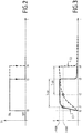
- the figure 2 represents, as a function of time t, the evolution of a control signal of the switch T1 between its on states, denoted “ON” and blocking, denoted “OFF” emitted by the module 2206.
- Note t0 instant called “trigger time”, from which the module 2206 sends a trip command to switch the switch T1 in the on state.
- the rate at which the current increases from the instant t0 depends on the position of the coupling member 2102. Depending on whether the member 2102 is in the rest position or in the triggered position, the inductance value of the 2101 coil is not the same. Here, the inductance of the coil 2101 is higher when the member 2102 is in the idle state. In fact, the response of the coil 2101 to the current flowing through it is different.
- the curve C1 represents the change in the intensity of the current flowing in the coil 2101 after the instant t0 when the member 2102 is in the tripped position.
- t1 the moment from which this current exceeds the threshold I-min. After this time t1, the current continues to increase until reaching the I-max limit current.
- the excitation module 2206 counts down the elapsed time, for example by means of a timer, from the instant t1, while keeping the switch T1 in the on state.
- the excitation module 2206 sends an interrupt command at a time t3.
- the switch T1 returns to its blocking state and the current thus ceases to flow in the coil 2101.
- the curve C2 represents the change in the intensity of the current flowing in the coil after the instant t0 when the member 2102 is in the rest position.
- t2 the instant from which the current exceeds the threshold value I MIN .
- I MIN the threshold value
- the current continues to increase until reaching the I-max limit current.
- the excitation module 2206 holds the switch T1 in the on state and sends an interrupt command at a time t4 at the expiration of the delay T-on. The current then ceases to flow through the coil 2101.
- the excitation module 2206 does not allow the circulation of an electric current longer than necessary to form a pulse of duration T-on, which reduces the electrical consumption of the trigger 20, and thus reduces the heat dissipation.
- the closing time of transistor T1 as being equal to the difference of times t4 and t0, based on the worst case scenario, which is that where the self inductance of the coil is minimal, so as to be sure to always have a pulse of duration at least equal to the duration T-one whatever the state of the coil 2101.
- the duration of the pulse would have been too long, since the current would have continued to be applied between instants t3 and t4, then the coil 2101 had received enough energy for the displacement of the organ 2102 is ensured. It would therefore have generated excessive heating for nothing, because the current supplied between times t1 and t3 is sufficient to excite the coil and cause switching.
- the excitation module 2206 comprises a detection module configured to measure the nature of the control signal Vcmd and in particular to determine whether it is an electrical or alternating voltage. This determination is made here from the voltage of the rail Vdd.
- Synchronization with the control signal Vcmd makes it possible to generate the pulses of electric current when the latter has a minimum value, and thus to limit the electrical power consumed by the control device 220.
- the excitation module 2206 is programmed so that the delay between two consecutive pulses is less than or equal to 100 ms, preferably less than or equal to 50 ms.
- T-off This delay, or interval, is noted T-off and is defined as the time interval between two current pulses at an intensity value greater than or equal to the I-min threshold. In this example, the T-off delay is 40ms.
- the duty cycle between the T-on delay and the T-off delay is advantageously between 1 10 and 1 100 , preferably equal to 1 40 , which reduces the power consumed.
- the switching mechanisms 110 of the toggle type comprise an open limit position, denoted P1, and a dead position closing, noted P2. These points P1 and P2 correspond to intermediate positions of the switching mechanism between the open state and the closed state.
- the point P1 corresponds to the position of the mechanism 110 from which the opening of the circuit breaker is guaranteed. In other words, when the mechanism 110 passes the point P1 from the closed position, the opening of the circuit breaker 10 is guaranteed.
- the point P1 corresponds to the release position of an element of the trigger mechanism 110 known as the trigger half-moon.
- the point P1 coincides with the opening position of the circuit breaker.
- the point P2 corresponds to the position of the mechanism 110 from which the closure of the circuit breaker can no longer be prevented. In other words, when the mechanism 110 crosses the point P2 coming from the open position, the closure of the circuit breaker 10 is provided. This is due to the action of mechanical springs included within the switching mechanism 110.
- this choice of value of the T-off delay makes it possible to guarantee that at least one pulse is generated from the module 2206 when the switching mechanism 110 is between the points P1 and P2 during its movement between the closed and open states. . With this pulse, the coupling member 2102 is again moved to its tripped position and again forces the opening of the circuit breaker before the switching mechanism 110 crosses the point P2.
- control device 220 also comprises an analog excitation module 2208 configured to generate, in addition, a single pulse of electric current of intensity greater than or equal to the first predetermined threshold I-min, as soon as the signal is received. Vcmd command by the controller 220.
- This analog excitation module 2208 is distinct from the excitation module 2206. Similarly, the single current pulse generated using this module 2208 is distinct from the series of pulses generated by means of the excitation module. 2206.
- the module 2208 comprises a comparator 2210 and a monostable flip-flop 2211.
- the control device 220 comprises meanwhile a controllable switch T2, for example identical to the switch T1.
- the switch T2 is here connected in parallel with the switch T1 between the source 2201 and the ground GND.
- the switch T2 plays, vis-à-vis the source 2201, a role similar to that described for the switch T1 with reference to the module 2206.
- the comparator 2210 is configured to compare the supply voltage value Vcc with a predefined reference value Vref.
- the comparator 2210 delivers a voltage, here denoted V1, to an input of the monostable flip-flop 2211.
- Vref is equal to 3 volts.
- Monostable flip-flop 2211 is configured to output a single output voltage pulse, which pulse has a predefined duration T '. This output is connected to a control electrode of the transistor T2 and acts as a switching command of the switch T2.
- the monostable flip-flop 2211 is chosen so as to have a duration T 'long enough to guarantee that the pulse of electric current generated has a duration greater than the duration T-on.
- the duration T ' is here equal to 18 ms.
- the switch T2 can be omitted.
- the module 2208 is adapted to control the switch T1 in parallel with the module 2206, for example by means of an "AND" logic gate which collects the commands issued by the modules 2206 and 2208 and which consequently controls the switch T1.
- the module 2208 is used in addition to the module 2206 and makes it possible to ensure that at least one pulse of electric current is injected into the coil 2201 as soon as the control signal Vcmd is received on the input 230, even in case of failure. of the module 2206.
- This single pulse has a duration and intensity sufficient to ensure the movement of the member 2102 to its tripped position.
- the module 2208 is made from simple analog components, and not from programmable microcontrollers or microprocessors, it has a more reliable and robust operation than the module 2206. This ensures a good operational safety of the module. trigger 20.
- the module 2208 does not allow to optimize the duration of the single pulse as finely as the module 2206 allows, this is not detrimental since only one current pulse is generated. by means of the module 2208 each time the control signal Vcmd is initiated. The additional energy cost is thus minimal.
- the trip unit 20 has an average consumption, in steady state, of less than or equal to 1 W and a transient consumption during power-up, that is to say the reception of the signal.
- Vcmd control is less than or equal to 10 W.
- the average steady-state consumption is greater than 5 W and transient consumption is greater than 30 W. Thanks to the In the invention, the heat dissipation is considerably reduced.
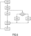
- the circuit breaker 10 is in a closed state, allowing the passage of an electric power current between its input and output terminals.
- No control signal Vcmd is received on the input 230.
- the coupling member 2102 is held in the home position. No electric current is injected into the coil 2101.
- control signal Vcmd is applied to the input 230 to the trigger 20, for example in response to the action of a user who press an emergency stop button to request opening of the circuit breaker 10.
- This voltage Vcmd feeds the rectifier 2209 and therefore the source 2201. Since the transistors T1 and T2 are both in the open state, no current flows at that moment through the coil 2101. The source 2201 therefore does not charge any electric current at that time. However, the voltage regulator 2202 generates the voltage Vcc on the power rail, which in turn powers the excitation modules 2206 and 2208.
- the excitation module 2208 controls the generation, by the source 2201, of a single current pulse to the coil 2101.
- the comparator 2210 delivers the voltage V1 to the input of the monostable flip-flop 2211.
- the monostable flip-flop 2211 goes into an excited state during the duration T ', during which it outputs a non-zero voltage V2, then returns to a state of rest at the end of this period T'. In doing so, the monostable flip-flop 2211 sends an opening switching and then closing order of the switch T2, separated by this delay T '.
- the coil 2101 demagnetizes the magnet and allows the spring to move to its relaxed position, which allows the displacement of the coupling member 2102 from its rest state to the triggered state .
- the coupling member 2102 acts on the switching mechanism 110 which causes the circuit breaker 10 to open.
- the excitation module 2206 is powered by the supply voltage Vcc in order to generate the series of current pulses.
- the excitation module 2206 automatically detects whether the control signal Vcmd is a DC voltage or an AC voltage.
- the current pulses are generated periodically over time, here with a delay equal to the T-off delay.
- the excitation module 2206 detects, by virtue of the current probe 2205, the instant from which the current flowing in the coil 2101 becomes greater than or equal to the threshold voltage I-min and then sends an interrupt command of the switch T1 on expiration of the delay T-on after this instant.
- the control signal Vcmd is determined as being an alternating voltage
- the current pulses are generated. synchronously with the instants for which the control signal Vcmd is detected as taking a zero value. More precisely, it is the tripping times t0 for which the excitation module 2206 sends a tripping order of the switch T1 which are synchronized with the times for which the control signal Vcmd is detected as taking a zero value.
- the generation of each of the pulses from this triggering instant t0 is here the same as that described for step 1010.
- the pulses generated by means of the excitation module 2206 make it possible to bring and / or maintain the circuit breaker 10 in the open state.
- the excitation module 2206 continues to generate the pulses so that the coil 2101 continues to demagnetize the magnet so as to allow the spring of remain in its relaxed position and thus maintain the coupling member 2102 in its triggered state.
- control signal Vcmd ceases to be applied and is no longer received on the input 230.
- the source 2201 is interrupted and the supply voltage Vcc becomes zero.
- the excitation module 2206 then stops working, and no electric current pulse is sent into the coil 2101.
Landscapes
- Physics & Mathematics (AREA)
- Electromagnetism (AREA)
- Engineering & Computer Science (AREA)
- Power Engineering (AREA)
- Breakers (AREA)
- Keying Circuit Devices (AREA)
- Relay Circuits (AREA)
- Driving Mechanisms And Operating Circuits Of Arc-Extinguishing High-Tension Switches (AREA)
Priority Applications (1)
| Application Number | Priority Date | Filing Date | Title |
|---|---|---|---|
| PL17187020T PL3288059T3 (pl) | 2016-08-23 | 2017-08-21 | Sterowany wyzwalacz do wyłącznika elektrycznego |
Applications Claiming Priority (1)
| Application Number | Priority Date | Filing Date | Title |
|---|---|---|---|
| FR1657867A FR3055465B1 (fr) | 2016-08-23 | 2016-08-23 | Declencheur commandable pour un disjoncteur electrique |
Publications (2)
| Publication Number | Publication Date |
|---|---|
| EP3288059A1 true EP3288059A1 (de) | 2018-02-28 |
| EP3288059B1 EP3288059B1 (de) | 2019-01-23 |
Family
ID=57680352
Family Applications (1)
| Application Number | Title | Priority Date | Filing Date |
|---|---|---|---|
| EP17187020.7A Active EP3288059B1 (de) | 2016-08-23 | 2017-08-21 | Steuerbarer auslöser für einen elektrischen trennschalter |
Country Status (8)
| Country | Link |
|---|---|
| US (1) | US10249461B2 (de) |
| EP (1) | EP3288059B1 (de) |
| CN (1) | CN107768204B (de) |
| BR (1) | BR102017013872B1 (de) |
| ES (1) | ES2721229T3 (de) |
| FR (1) | FR3055465B1 (de) |
| PL (1) | PL3288059T3 (de) |
| RU (1) | RU2752849C2 (de) |
Cited By (1)
| Publication number | Priority date | Publication date | Assignee | Title |
|---|---|---|---|---|
| FR3114680A1 (fr) * | 2020-09-30 | 2022-04-01 | Schneider Electric Industries Sas | Dispositif de communication pour un appareil de commutation électrique |
Families Citing this family (3)
| Publication number | Priority date | Publication date | Assignee | Title |
|---|---|---|---|---|
| BE1026605B1 (de) * | 2018-09-12 | 2020-04-09 | Phoenix Contact Gmbh & Co | Relaismodul |
| CN112992619B (zh) * | 2021-02-07 | 2022-06-03 | 青岛博宁福田智能交通科技发展有限公司 | 一种紧急按钮开关接口及地铁闸机 |
| CN116666172B (zh) * | 2023-06-16 | 2024-04-05 | 上海正泰智能科技有限公司 | 断路器控制方法以及断路器系统 |
Citations (6)
| Publication number | Priority date | Publication date | Assignee | Title |
|---|---|---|---|---|
| US5180051A (en) * | 1991-06-28 | 1993-01-19 | Square D Company | Remote control circuit breaker |
| WO1997000525A1 (de) * | 1995-06-16 | 1997-01-03 | Siemens Aktiengesellschaft | Schaltungsanordnung zum betrieb eines elektromagneten |
| DE19635358A1 (de) * | 1996-08-22 | 1998-02-26 | Siemens Ag | Schaltungsanordnung mit einem elektromagnetischen Relais |
| EP1209712A1 (de) * | 2000-11-21 | 2002-05-29 | Hager Electro S.A. | Fernsteuervorrictung für modulares Schutzgerät |
| US20050135040A1 (en) * | 2003-12-11 | 2005-06-23 | Anden Co., Ltd. | Relay device having holding current stabilizing and limiting circuit |
| US20150171614A1 (en) * | 2013-12-16 | 2015-06-18 | Eaton Corporation | Shunt trip control circuits using shunt trip signal accumulator and methods of operating the same |
Family Cites Families (8)
| Publication number | Priority date | Publication date | Assignee | Title |
|---|---|---|---|---|
| SU1105956A1 (ru) * | 1982-09-02 | 1984-07-30 | Ленинградское Электромашиностроительное Объединение "Электросила" Им.С.М.Кирова | Пускатель-автомат |
| SU1576927A1 (ru) * | 1988-06-27 | 1990-07-07 | Военно-воздушная инженерная Краснознаменная академия им.проф.Н.Е.Жуковского | Автоматический выключатель с электронным управлением |
| SU1700633A1 (ru) * | 1989-10-18 | 1991-12-23 | Московский энергетический институт | Автоматический выключатель с дистанционным управлением |
| US5539608A (en) * | 1993-02-25 | 1996-07-23 | Eaton Corporation | Electronic interlock for electromagnetic contactor |
| US5757598A (en) * | 1996-12-27 | 1998-05-26 | Tower Manufacturing Corporation | Ground fault circuit interrupter |
| US6052266A (en) * | 1998-10-01 | 2000-04-18 | Tower Manufacturing Corporation | Ground fault circuit interrupter |
| CN100466134C (zh) * | 1999-07-12 | 2009-03-04 | 三菱电机株式会社 | 电磁接触器 |
| RU2214662C2 (ru) * | 2001-08-09 | 2003-10-20 | Пономаренко Андрей Иванович | Способ управления устройством защитного отключения |
-
2016
- 2016-08-23 FR FR1657867A patent/FR3055465B1/fr active Active
-
2017
- 2017-06-27 BR BR102017013872-0A patent/BR102017013872B1/pt active IP Right Grant
- 2017-08-03 US US15/668,199 patent/US10249461B2/en active Active
- 2017-08-16 RU RU2017129112A patent/RU2752849C2/ru active
- 2017-08-16 CN CN201710700948.1A patent/CN107768204B/zh active Active
- 2017-08-21 ES ES17187020T patent/ES2721229T3/es active Active
- 2017-08-21 PL PL17187020T patent/PL3288059T3/pl unknown
- 2017-08-21 EP EP17187020.7A patent/EP3288059B1/de active Active
Patent Citations (6)
| Publication number | Priority date | Publication date | Assignee | Title |
|---|---|---|---|---|
| US5180051A (en) * | 1991-06-28 | 1993-01-19 | Square D Company | Remote control circuit breaker |
| WO1997000525A1 (de) * | 1995-06-16 | 1997-01-03 | Siemens Aktiengesellschaft | Schaltungsanordnung zum betrieb eines elektromagneten |
| DE19635358A1 (de) * | 1996-08-22 | 1998-02-26 | Siemens Ag | Schaltungsanordnung mit einem elektromagnetischen Relais |
| EP1209712A1 (de) * | 2000-11-21 | 2002-05-29 | Hager Electro S.A. | Fernsteuervorrictung für modulares Schutzgerät |
| US20050135040A1 (en) * | 2003-12-11 | 2005-06-23 | Anden Co., Ltd. | Relay device having holding current stabilizing and limiting circuit |
| US20150171614A1 (en) * | 2013-12-16 | 2015-06-18 | Eaton Corporation | Shunt trip control circuits using shunt trip signal accumulator and methods of operating the same |
Cited By (2)
| Publication number | Priority date | Publication date | Assignee | Title |
|---|---|---|---|---|
| FR3114680A1 (fr) * | 2020-09-30 | 2022-04-01 | Schneider Electric Industries Sas | Dispositif de communication pour un appareil de commutation électrique |
| US11881370B2 (en) | 2020-09-30 | 2024-01-23 | Schneider Electric Industries Sas | Communication device for an electrical switching unit |
Also Published As
| Publication number | Publication date |
|---|---|
| PL3288059T3 (pl) | 2019-07-31 |
| BR102017013872A2 (pt) | 2018-03-13 |
| FR3055465B1 (fr) | 2019-11-22 |
| BR102017013872B1 (pt) | 2023-12-19 |
| EP3288059B1 (de) | 2019-01-23 |
| FR3055465A1 (fr) | 2018-03-02 |
| CN107768204B (zh) | 2021-08-10 |
| ES2721229T3 (es) | 2019-07-29 |
| US10249461B2 (en) | 2019-04-02 |
| RU2017129112A (ru) | 2019-02-18 |
| US20180061604A1 (en) | 2018-03-01 |
| RU2017129112A3 (de) | 2020-09-28 |
| CN107768204A (zh) | 2018-03-06 |
| RU2752849C2 (ru) | 2021-08-11 |
Similar Documents
| Publication | Publication Date | Title |
|---|---|---|
| EP3288059B1 (de) | Steuerbarer auslöser für einen elektrischen trennschalter | |
| EP2019396B1 (de) | Elektromagnetisches Stellglied mit mindestens zwei Wicklungen | |
| EP1009006B1 (de) | Standardeinrichtung zur Steuerung eines Elektromagneten zum Öffnen oder Schliessen eines Schutzschalters | |
| CA1253578A (fr) | Systeme de soudage ou de coupage plasma muni d'une temporisation | |
| EP2899343B1 (de) | Vorrichtung zur Aufhebung der magnetischen Remanenz für elektromagnetische Schlösser | |
| CH628423A5 (fr) | Circuit electrique pour l'allumage d'un detonateur. | |
| EP1009004B1 (de) | Einrichtung zur Steuerung eines Elektromagneten, mit Erfassung von unbeabsichtigtem Bewegen des beweglichen Kerns eines Elektromagneten | |
| EP0841670B1 (de) | Stromwandler, Auflöser und Schutzschalter mit solchem Stromwandler | |
| FR2618270A1 (fr) | Circuit et appareillage pour l'alimentation protegee d'une charge a l'aide d'interrupteurs statiques et electromecaniques. | |
| FR2601811A1 (fr) | Circuit de commande pour la bobine excitatrice d'un electro-aimant | |
| FR2919109A1 (fr) | Dispositif de detection de position d'une partie mobile dans un appareil electrique interrupteur. | |
| FR2488476A1 (fr) | Circuits de commande et ensembles de commutation electrique comprenant de tels circuits | |
| FR2828668A1 (fr) | Retracteur de ceinture de securite | |
| EP0093804B1 (de) | Elektrische Schaltung für die Zündung eines Detonators | |
| EP0720193A1 (de) | Elektrisches Steuergerät zum Öffnen und Schliessen eines Last- oder Leistungsschalters | |
| FR2612276A1 (fr) | Procedes et dispositifs inducteurs electromagnetiques bistables pour electrovannes et circuits electroniques connexes, a tres faible consommation electrique; avec application a l'arrosage automatique asservi au besoin en eau des plantes a la profondeur desiree | |
| EP3291271B1 (de) | Steuerungsverfahren einer betätigungsvorrichtung und entsprechende betätigungsvorrichtung und schaltvorrichtung | |
| CA1227832A (fr) | Appareil de detection de la defaillance d'une alimentation electrique a decoupage | |
| EP0424283A1 (de) | Steuervorrichtung für einen ferngesteuerten Schalter | |
| FR2803956A1 (fr) | Dispositif et procede pour alimenter une bobine de commande d'un contacteur electrique, notamment d'un contacteur de puissance | |
| FR2923936A1 (fr) | Circuit de commande d'un actionneur electromagnetique a double bobines et actionneur electromagnetique a double bobines comportant un tel circuit de commande. | |
| EP4139946B1 (de) | Leitungsschutzschalter mit elektronischer auslösesteuerung | |
| EP0021867A1 (de) | Gegen Schwankungen der Eingangsspannung und der Ausgangsleistung geregelte Zerhacker-Spannungsversorgungsschaltung, insbesondere für Fernsehempfänger | |
| CH600518A5 (en) | Excitation circuit for linear electromagnetic control | |
| FR2951015A1 (fr) | Disjoncteur a limiteur de courant |
Legal Events
| Date | Code | Title | Description |
|---|---|---|---|
| PUAI | Public reference made under article 153(3) epc to a published international application that has entered the european phase |
Free format text: ORIGINAL CODE: 0009012 |
|
| STAA | Information on the status of an ep patent application or granted ep patent |
Free format text: STATUS: THE APPLICATION HAS BEEN PUBLISHED |
|
| AK | Designated contracting states |
Kind code of ref document: A1 Designated state(s): AL AT BE BG CH CY CZ DE DK EE ES FI FR GB GR HR HU IE IS IT LI LT LU LV MC MK MT NL NO PL PT RO RS SE SI SK SM TR |
|
| AX | Request for extension of the european patent |
Extension state: BA ME |
|
| STAA | Information on the status of an ep patent application or granted ep patent |
Free format text: STATUS: REQUEST FOR EXAMINATION WAS MADE |
|
| 17P | Request for examination filed |
Effective date: 20180801 |
|
| RBV | Designated contracting states (corrected) |
Designated state(s): AL AT BE BG CH CY CZ DE DK EE ES FI FR GB GR HR HU IE IS IT LI LT LU LV MC MK MT NL NO PL PT RO RS SE SI SK SM TR |
|
| GRAP | Despatch of communication of intention to grant a patent |
Free format text: ORIGINAL CODE: EPIDOSNIGR1 |
|
| STAA | Information on the status of an ep patent application or granted ep patent |
Free format text: STATUS: GRANT OF PATENT IS INTENDED |
|
| RIC1 | Information provided on ipc code assigned before grant |
Ipc: H01H 89/08 20060101ALI20180817BHEP Ipc: H01H 71/68 20060101AFI20180817BHEP |
|
| INTG | Intention to grant announced |
Effective date: 20180914 |
|
| RIN1 | Information on inventor provided before grant (corrected) |
Inventor name: URANKAR, LIONEL Inventor name: BORDET, BRUNO |
|
| GRAS | Grant fee paid |
Free format text: ORIGINAL CODE: EPIDOSNIGR3 |
|
| GRAA | (expected) grant |
Free format text: ORIGINAL CODE: 0009210 |
|
| STAA | Information on the status of an ep patent application or granted ep patent |
Free format text: STATUS: THE PATENT HAS BEEN GRANTED |
|
| AK | Designated contracting states |
Kind code of ref document: B1 Designated state(s): AL AT BE BG CH CY CZ DE DK EE ES FI FR GB GR HR HU IE IS IT LI LT LU LV MC MK MT NL NO PL PT RO RS SE SI SK SM TR |
|
| REG | Reference to a national code |
Ref country code: GB Ref legal event code: FG4D Free format text: NOT ENGLISH |
|
| REG | Reference to a national code |
Ref country code: CH Ref legal event code: EP |
|
| REG | Reference to a national code |
Ref country code: AT Ref legal event code: REF Ref document number: 1092123 Country of ref document: AT Kind code of ref document: T Effective date: 20190215 |
|
| REG | Reference to a national code |
Ref country code: IE Ref legal event code: FG4D Free format text: LANGUAGE OF EP DOCUMENT: FRENCH |
|
| REG | Reference to a national code |
Ref country code: DE Ref legal event code: R096 Ref document number: 602017001905 Country of ref document: DE |
|
| REG | Reference to a national code |
Ref country code: NL Ref legal event code: MP Effective date: 20190123 |
|
| PG25 | Lapsed in a contracting state [announced via postgrant information from national office to epo] |
Ref country code: NL Free format text: LAPSE BECAUSE OF FAILURE TO SUBMIT A TRANSLATION OF THE DESCRIPTION OR TO PAY THE FEE WITHIN THE PRESCRIBED TIME-LIMIT Effective date: 20190123 |
|
| REG | Reference to a national code |
Ref country code: ES Ref legal event code: FG2A Ref document number: 2721229 Country of ref document: ES Kind code of ref document: T3 Effective date: 20190729 |
|
| PG25 | Lapsed in a contracting state [announced via postgrant information from national office to epo] |
Ref country code: PT Free format text: LAPSE BECAUSE OF FAILURE TO SUBMIT A TRANSLATION OF THE DESCRIPTION OR TO PAY THE FEE WITHIN THE PRESCRIBED TIME-LIMIT Effective date: 20190523 Ref country code: FI Free format text: LAPSE BECAUSE OF FAILURE TO SUBMIT A TRANSLATION OF THE DESCRIPTION OR TO PAY THE FEE WITHIN THE PRESCRIBED TIME-LIMIT Effective date: 20190123 Ref country code: LT Free format text: LAPSE BECAUSE OF FAILURE TO SUBMIT A TRANSLATION OF THE DESCRIPTION OR TO PAY THE FEE WITHIN THE PRESCRIBED TIME-LIMIT Effective date: 20190123 Ref country code: SE Free format text: LAPSE BECAUSE OF FAILURE TO SUBMIT A TRANSLATION OF THE DESCRIPTION OR TO PAY THE FEE WITHIN THE PRESCRIBED TIME-LIMIT Effective date: 20190123 Ref country code: NO Free format text: LAPSE BECAUSE OF FAILURE TO SUBMIT A TRANSLATION OF THE DESCRIPTION OR TO PAY THE FEE WITHIN THE PRESCRIBED TIME-LIMIT Effective date: 20190423 |
|
| REG | Reference to a national code |
Ref country code: AT Ref legal event code: MK05 Ref document number: 1092123 Country of ref document: AT Kind code of ref document: T Effective date: 20190123 |
|
| PG25 | Lapsed in a contracting state [announced via postgrant information from national office to epo] |
Ref country code: RS Free format text: LAPSE BECAUSE OF FAILURE TO SUBMIT A TRANSLATION OF THE DESCRIPTION OR TO PAY THE FEE WITHIN THE PRESCRIBED TIME-LIMIT Effective date: 20190123 Ref country code: HR Free format text: LAPSE BECAUSE OF FAILURE TO SUBMIT A TRANSLATION OF THE DESCRIPTION OR TO PAY THE FEE WITHIN THE PRESCRIBED TIME-LIMIT Effective date: 20190123 Ref country code: GR Free format text: LAPSE BECAUSE OF FAILURE TO SUBMIT A TRANSLATION OF THE DESCRIPTION OR TO PAY THE FEE WITHIN THE PRESCRIBED TIME-LIMIT Effective date: 20190424 Ref country code: IS Free format text: LAPSE BECAUSE OF FAILURE TO SUBMIT A TRANSLATION OF THE DESCRIPTION OR TO PAY THE FEE WITHIN THE PRESCRIBED TIME-LIMIT Effective date: 20190523 Ref country code: LV Free format text: LAPSE BECAUSE OF FAILURE TO SUBMIT A TRANSLATION OF THE DESCRIPTION OR TO PAY THE FEE WITHIN THE PRESCRIBED TIME-LIMIT Effective date: 20190123 Ref country code: BG Free format text: LAPSE BECAUSE OF FAILURE TO SUBMIT A TRANSLATION OF THE DESCRIPTION OR TO PAY THE FEE WITHIN THE PRESCRIBED TIME-LIMIT Effective date: 20190423 |
|
| REG | Reference to a national code |
Ref country code: DE Ref legal event code: R097 Ref document number: 602017001905 Country of ref document: DE |
|
| PG25 | Lapsed in a contracting state [announced via postgrant information from national office to epo] |
Ref country code: DK Free format text: LAPSE BECAUSE OF FAILURE TO SUBMIT A TRANSLATION OF THE DESCRIPTION OR TO PAY THE FEE WITHIN THE PRESCRIBED TIME-LIMIT Effective date: 20190123 Ref country code: EE Free format text: LAPSE BECAUSE OF FAILURE TO SUBMIT A TRANSLATION OF THE DESCRIPTION OR TO PAY THE FEE WITHIN THE PRESCRIBED TIME-LIMIT Effective date: 20190123 Ref country code: RO Free format text: LAPSE BECAUSE OF FAILURE TO SUBMIT A TRANSLATION OF THE DESCRIPTION OR TO PAY THE FEE WITHIN THE PRESCRIBED TIME-LIMIT Effective date: 20190123 Ref country code: CZ Free format text: LAPSE BECAUSE OF FAILURE TO SUBMIT A TRANSLATION OF THE DESCRIPTION OR TO PAY THE FEE WITHIN THE PRESCRIBED TIME-LIMIT Effective date: 20190123 Ref country code: SK Free format text: LAPSE BECAUSE OF FAILURE TO SUBMIT A TRANSLATION OF THE DESCRIPTION OR TO PAY THE FEE WITHIN THE PRESCRIBED TIME-LIMIT Effective date: 20190123 Ref country code: AL Free format text: LAPSE BECAUSE OF FAILURE TO SUBMIT A TRANSLATION OF THE DESCRIPTION OR TO PAY THE FEE WITHIN THE PRESCRIBED TIME-LIMIT Effective date: 20190123 |
|
| PG25 | Lapsed in a contracting state [announced via postgrant information from national office to epo] |
Ref country code: SM Free format text: LAPSE BECAUSE OF FAILURE TO SUBMIT A TRANSLATION OF THE DESCRIPTION OR TO PAY THE FEE WITHIN THE PRESCRIBED TIME-LIMIT Effective date: 20190123 |
|
| PLBE | No opposition filed within time limit |
Free format text: ORIGINAL CODE: 0009261 |
|
| STAA | Information on the status of an ep patent application or granted ep patent |
Free format text: STATUS: NO OPPOSITION FILED WITHIN TIME LIMIT |
|
| PG25 | Lapsed in a contracting state [announced via postgrant information from national office to epo] |
Ref country code: AT Free format text: LAPSE BECAUSE OF FAILURE TO SUBMIT A TRANSLATION OF THE DESCRIPTION OR TO PAY THE FEE WITHIN THE PRESCRIBED TIME-LIMIT Effective date: 20190123 |
|
| 26N | No opposition filed |
Effective date: 20191024 |
|
| PG25 | Lapsed in a contracting state [announced via postgrant information from national office to epo] |
Ref country code: SI Free format text: LAPSE BECAUSE OF FAILURE TO SUBMIT A TRANSLATION OF THE DESCRIPTION OR TO PAY THE FEE WITHIN THE PRESCRIBED TIME-LIMIT Effective date: 20190123 |
|
| PG25 | Lapsed in a contracting state [announced via postgrant information from national office to epo] |
Ref country code: TR Free format text: LAPSE BECAUSE OF FAILURE TO SUBMIT A TRANSLATION OF THE DESCRIPTION OR TO PAY THE FEE WITHIN THE PRESCRIBED TIME-LIMIT Effective date: 20190123 |
|
| PG25 | Lapsed in a contracting state [announced via postgrant information from national office to epo] |
Ref country code: LU Free format text: LAPSE BECAUSE OF NON-PAYMENT OF DUE FEES Effective date: 20190821 Ref country code: MC Free format text: LAPSE BECAUSE OF FAILURE TO SUBMIT A TRANSLATION OF THE DESCRIPTION OR TO PAY THE FEE WITHIN THE PRESCRIBED TIME-LIMIT Effective date: 20190123 |
|
| REG | Reference to a national code |
Ref country code: BE Ref legal event code: MM Effective date: 20190831 |
|
| PG25 | Lapsed in a contracting state [announced via postgrant information from national office to epo] |
Ref country code: IE Free format text: LAPSE BECAUSE OF NON-PAYMENT OF DUE FEES Effective date: 20190821 |
|
| PG25 | Lapsed in a contracting state [announced via postgrant information from national office to epo] |
Ref country code: BE Free format text: LAPSE BECAUSE OF NON-PAYMENT OF DUE FEES Effective date: 20190831 |
|
| REG | Reference to a national code |
Ref country code: CH Ref legal event code: PL |
|
| PG25 | Lapsed in a contracting state [announced via postgrant information from national office to epo] |
Ref country code: CH Free format text: LAPSE BECAUSE OF NON-PAYMENT OF DUE FEES Effective date: 20200831 Ref country code: LI Free format text: LAPSE BECAUSE OF NON-PAYMENT OF DUE FEES Effective date: 20200831 |
|
| PG25 | Lapsed in a contracting state [announced via postgrant information from national office to epo] |
Ref country code: CY Free format text: LAPSE BECAUSE OF FAILURE TO SUBMIT A TRANSLATION OF THE DESCRIPTION OR TO PAY THE FEE WITHIN THE PRESCRIBED TIME-LIMIT Effective date: 20190123 |
|
| PG25 | Lapsed in a contracting state [announced via postgrant information from national office to epo] |
Ref country code: MT Free format text: LAPSE BECAUSE OF FAILURE TO SUBMIT A TRANSLATION OF THE DESCRIPTION OR TO PAY THE FEE WITHIN THE PRESCRIBED TIME-LIMIT Effective date: 20190123 Ref country code: HU Free format text: LAPSE BECAUSE OF FAILURE TO SUBMIT A TRANSLATION OF THE DESCRIPTION OR TO PAY THE FEE WITHIN THE PRESCRIBED TIME-LIMIT; INVALID AB INITIO Effective date: 20170821 |
|
| PG25 | Lapsed in a contracting state [announced via postgrant information from national office to epo] |
Ref country code: MK Free format text: LAPSE BECAUSE OF FAILURE TO SUBMIT A TRANSLATION OF THE DESCRIPTION OR TO PAY THE FEE WITHIN THE PRESCRIBED TIME-LIMIT Effective date: 20190123 |
|
| PGFP | Annual fee paid to national office [announced via postgrant information from national office to epo] |
Ref country code: IT Payment date: 20230822 Year of fee payment: 7 Ref country code: GB Payment date: 20230822 Year of fee payment: 7 Ref country code: ES Payment date: 20230914 Year of fee payment: 7 |
|
| PGFP | Annual fee paid to national office [announced via postgrant information from national office to epo] |
Ref country code: PL Payment date: 20230809 Year of fee payment: 7 Ref country code: FR Payment date: 20230824 Year of fee payment: 7 Ref country code: DE Payment date: 20230828 Year of fee payment: 7 |