EP3172832B1 - Verfahren und einheit zum steuern und/oder schützen eines aktuators eines teils einer mobilen ausrüstung eines gebäudes - Google Patents
Verfahren und einheit zum steuern und/oder schützen eines aktuators eines teils einer mobilen ausrüstung eines gebäudes Download PDFInfo
- Publication number
- EP3172832B1 EP3172832B1 EP15753118.7A EP15753118A EP3172832B1 EP 3172832 B1 EP3172832 B1 EP 3172832B1 EP 15753118 A EP15753118 A EP 15753118A EP 3172832 B1 EP3172832 B1 EP 3172832B1
- Authority
- EP
- European Patent Office
- Prior art keywords
- control
- protection
- motor
- actuator
- representative
- Prior art date
- Legal status (The legal status is an assumption and is not a legal conclusion. Google has not performed a legal analysis and makes no representation as to the accuracy of the status listed.)
- Active
Links
- 238000000034 method Methods 0.000 title claims description 24
- 238000005070 sampling Methods 0.000 claims description 12
- 238000012545 processing Methods 0.000 claims description 10
- 230000010287 polarization Effects 0.000 claims description 9
- 230000002123 temporal effect Effects 0.000 claims description 8
- 230000001360 synchronised effect Effects 0.000 claims description 5
- 238000004590 computer program Methods 0.000 claims description 4
- 238000004804 winding Methods 0.000 description 20
- 230000008859 change Effects 0.000 description 19
- 230000006870 function Effects 0.000 description 7
- 230000033228 biological regulation Effects 0.000 description 6
- 230000001276 controlling effect Effects 0.000 description 5
- 238000010586 diagram Methods 0.000 description 5
- 238000005259 measurement Methods 0.000 description 5
- 238000001514 detection method Methods 0.000 description 4
- 230000001105 regulatory effect Effects 0.000 description 4
- 230000011664 signaling Effects 0.000 description 4
- 230000007704 transition Effects 0.000 description 4
- 238000006243 chemical reaction Methods 0.000 description 3
- 230000005672 electromagnetic field Effects 0.000 description 3
- 238000001914 filtration Methods 0.000 description 2
- 230000009897 systematic effect Effects 0.000 description 2
- 238000012795 verification Methods 0.000 description 2
- 101100502609 Caenorhabditis elegans fem-1 gene Proteins 0.000 description 1
- 101100502610 Caenorhabditis elegans fem-2 gene Proteins 0.000 description 1
- 101100334582 Drosophila melanogaster Fem-1 gene Proteins 0.000 description 1
- 241001080024 Telles Species 0.000 description 1
- 230000002159 abnormal effect Effects 0.000 description 1
- 238000004364 calculation method Methods 0.000 description 1
- 239000003990 capacitor Substances 0.000 description 1
- 239000013256 coordination polymer Substances 0.000 description 1
- 230000005347 demagnetization Effects 0.000 description 1
- 230000000694 effects Effects 0.000 description 1
- 235000021183 entrée Nutrition 0.000 description 1
- 239000004744 fabric Substances 0.000 description 1
- 101150014310 fem-3 gene Proteins 0.000 description 1
- 230000005669 field effect Effects 0.000 description 1
- 230000002045 lasting effect Effects 0.000 description 1
- 230000007257 malfunction Effects 0.000 description 1
- 230000005055 memory storage Effects 0.000 description 1
- 229910044991 metal oxide Inorganic materials 0.000 description 1
- 150000004706 metal oxides Chemical class 0.000 description 1
- 230000004048 modification Effects 0.000 description 1
- 238000012986 modification Methods 0.000 description 1
- 230000008569 process Effects 0.000 description 1
- 230000001681 protective effect Effects 0.000 description 1
- 238000005096 rolling process Methods 0.000 description 1
- 239000004065 semiconductor Substances 0.000 description 1
Images


Classifications
-
- H—ELECTRICITY
- H02—GENERATION; CONVERSION OR DISTRIBUTION OF ELECTRIC POWER
- H02P—CONTROL OR REGULATION OF ELECTRIC MOTORS, ELECTRIC GENERATORS OR DYNAMO-ELECTRIC CONVERTERS; CONTROLLING TRANSFORMERS, REACTORS OR CHOKE COILS
- H02P29/00—Arrangements for regulating or controlling electric motors, appropriate for both AC and DC motors
- H02P29/02—Providing protection against overload without automatic interruption of supply
- H02P29/024—Detecting a fault condition, e.g. short circuit, locked rotor, open circuit or loss of load
- H02P29/027—Detecting a fault condition, e.g. short circuit, locked rotor, open circuit or loss of load the fault being an over-current
-
- H—ELECTRICITY
- H02—GENERATION; CONVERSION OR DISTRIBUTION OF ELECTRIC POWER
- H02P—CONTROL OR REGULATION OF ELECTRIC MOTORS, ELECTRIC GENERATORS OR DYNAMO-ELECTRIC CONVERTERS; CONTROLLING TRANSFORMERS, REACTORS OR CHOKE COILS
- H02P29/00—Arrangements for regulating or controlling electric motors, appropriate for both AC and DC motors
- H02P29/02—Providing protection against overload without automatic interruption of supply
- H02P29/024—Detecting a fault condition, e.g. short circuit, locked rotor, open circuit or loss of load
- H02P29/0241—Detecting a fault condition, e.g. short circuit, locked rotor, open circuit or loss of load the fault being an overvoltage
Definitions
- the present invention relates to a method and a unit for controlling and / or protecting an actuator of mobile equipment in a building, the actuator comprising a motor of the type comprising a rotor and a stator.
- the present invention can for example be implemented for an actuator comprising an electronically commutated brushless direct current motor (or also called “BLDC”, acronym of the English expression BrushLess Direct Current).
- BLDC electronically commutated brushless direct current motor
- a motor of this type includes a rotor with permanent magnets and a stator with several windings.
- the motor further comprises a control system arranged to successively supply the windings with electrical energy.
- a control system arranged to successively supply the windings with electrical energy.
- the electromagnetic field generated by the successive power supply to the windings must be synchronized with the position of the rotor.
- control system comprises position sensors arranged to determine the position of the rotor.
- This type of motor can be regulated according to its speed of rotation. It is thus possible to limit the speed so that the speed of rotation does not exceed the maximum speed admissible by the mechanical elements of the actuator.
- This type of motor can also be regulated according to its torque. It is thus possible to limit the torque so that the torque does not exceed the maximum torque admissible by the mechanical elements of the actuator.
- the present invention aims to resolve all or part of the drawbacks mentioned above.
- the protection criteria can apply not only to the motor but also to all or part of all the components constituting the actuator. This is of course the motor but also the motor control electronics and the mechanical linkage elements of the actuator to the mobile equipment.
- each value sampled according to the first protection criterion is a systematic check.
- each pulse is measured and each pulse value that does not comply with the first protection criterion is detected.
- the set of sampled values acquired is subjected to a control according to the second protection criterion in order to detect an anomaly resulting in a lasting variation which may not lead to a violation of the first protection criterion.
- the instantaneous signal representative of the electric power supplied to the motor is the image of the torque supplied by the motor.
- a multitude of operating anomalies can thus be detected so as to protect, in particular, the motor from a current having too high a value which can cause, for example, a demagnetization of magnets in the case of a motor of the type with electronically commutated brushless direct current, or a torque greater than the maximum torque permitted by the motor.
- the rotor or the stator of the motor comprises a plurality of windings successively supplied in a variable manner to generate a rotary movement of the rotor, according to control sequences.
- the command sequences correspond to successive power supply configurations separated by transitions or command changes.
- switches can be interposed between the power supply to the motor and the windings so as to vary the power in the windings according to the power supply configurations.
- a sampled value is acquired between two command changes.
- the sampled value acquired corresponds to a last pulse of the instantaneous signal between two changes of control.
- the engine has at least a first operating mode, in particular an engine starting mode, and a second operating mode, in particular a stabilized operating mode, and in which the first protection criterion and / or the second actuator protection criterion is modified as a function of the engine operating mode.
- This arrangement makes it possible to adapt the protection, that is to say the triggering of the safe stop of the motor, according to the operating mode.
- a representative quantity from said set of acquired sampled values is determined, and the second actuator protection criterion is applied to said representative quantity.
- the representative quantity is not necessarily determined from each sampled value but only from the set of sampled values acquired. Thus, the determination of the representative quantity does not require a significant calculation effort.
- the stator of the motor comprises a plurality of windings successively subjected to the electric power supplied to the motor.
- the set of sampled values acquired corresponds to sampling synchronized with each last pulse before the change of the powered winding.
- a sampled value acquired subsequently to the sampled values acquired is added to the set of sampled values acquired, the representative quantity being determined at new after adding the sampled value acquired later.
- This arrangement makes it possible to continuously update the representative quantity.
- it is a variable representative quantity as a function of the evolution of the operation of the engine and not of a discrete representative quantity.
- the oldest sampled value acquired is deleted from the set of sampled values acquired.
- the representative quantity is a sliding average of the sampled values acquired.
- This arrangement makes it possible to determine a representative quantity corresponding to the evolution of the operation of the engine.
- the representative quantity is thus not disturbed by too old acquired sampled values.
- control according to the second criterion of protection of the actuator further comprises a comparison of a temporal evolution of representative quantities successively determined with a threshold temporal evolution.
- the threshold time change corresponds to a threshold of variation of the representative quantity over a given period of time.
- Failure to comply with the second actuator protection criterion may in particular correspond to the time change being exceeded by the quantities representative of the threshold time change.
- the second anomaly item of information sent following an exceeding of the threshold temporal change comprises an indication signaling the exceeding of the threshold temporal change.
- This arrangement makes it possible to detect a sudden increase or decrease in the instantaneous signal representative of the electrical supply supplied to the motor although the first criterion of protection of the actuator is always respected.
- the check according to the first protection criterion of the actuator comprises a comparison of each sampled value with a first threshold value.
- the first anomaly information is sent when the sampled value is greater than the first threshold value.
- the first threshold value is defined as corresponding to the lowest of the values relating to the instantaneous signal representative of the electrical power supplied to the motor, beyond which an anomaly appears.
- control according to the second criterion of protection of the actuator comprises a comparison of the representative quantity with a second threshold value.
- the second anomaly information is transmitted when the representative quantity is greater than the second threshold value.
- the second anomaly information item when a second anomaly information item is sent for a representative quantity greater than the second threshold value, the second anomaly information item comprises an indication signaling the crossing of the second threshold value.
- the second threshold value can be exceeded, even if the first criterion of protection of the actuator is met.
- this modification can be carried out for example by modifying the value of the first threshold and / or of the second threshold.
- the first threshold value is modified according to the operating mode of the engine, in particular the starting mode of the engine or the stabilized operating mode of the engine.
- This arrangement makes it possible to adapt the first threshold value to the operating mode of the engine. Indeed, the threshold values not to be exceeded for the signal representative of the electric power supply to the motor are not constant depending on the operating modes of the motor.
- the first threshold value is defined relative to a limiting current when the motor goes from a zero speed of rotation to a determined speed of rotation. This corresponds to the engine starting mode.
- said limit current corresponds to a maximum value of the current admissible by the actuator in operation.
- the first threshold value is defined relative to a limiting current when the motor has reached at least once the determined rotation speed after starting.
- said limit current corresponds to a maximum admissible value of the current, after passing through the motor, not to be exceeded so that the torque of the motor is below an operating limit value.
- the second threshold value is modified according to an engine operating mode, in particular the engine starting mode or the stabilized engine operating mode.
- This arrangement makes it possible to adapt the second threshold value to the operating mode of the engine. Indeed, the threshold values not to be exceeded for the instantaneous signal representative of the electric power supply to the motor are not constant according to the operating modes of the motor.
- the second threshold value is defined as equal to a limit current.
- said limit current corresponds to an average limit operating current, beyond which the torque of the motor is greater than the maximum torque admissible by the mechanical elements of the actuator.
- the second threshold value is defined as equal to a stabilized operating limit current when the engine has operated for a defined period of time following the start of the regulation of the speed of rotation.
- the present invention also relates to a computer program product comprising code instructions arranged to implement the steps of a control and / or protection method as described above.
- the present invention further relates to a control and / or protection unit provided with a processor comprising in memory the code instructions of a computer program product as described above, the control unit and / or protection being arranged to read an instantaneous signal representative of the electric power supplied to a motor of the type comprising a rotor and a stator.
- the instantaneous signal representative of the electrical power supplied to the motor is a voltage or an electrical current which is an image of the torque supplied by the motor.
- control and / or protection unit further comprises a signal generator arranged to deliver an instantaneous signal representative of the electrical power supplied to the motor, and a polarization element arranged to establish a default input signal instead of the instantaneous signal when the signal generator has a fault causing the absence of a signal.
- the biasing element is used to bias the input of the analog-to-digital converter during certain fault cases, in particular the breakage of an electronic component.
- the default input signal is detected.
- This arrangement prevents the reading of a random signal when an incident causes the instantaneous signal representative of the electric power supplied to the motor to be cut.
- the reading of a random signal will not necessarily lead to the detection of an anomaly by applying the first protection criterion and the second protection criterion of the actuator.
- the default input signal when it is read by the control and / or protection unit, is indeed detected as being an anomaly.
- control and / or protection unit comprises a digital processing unit, for example a microcontroller, the digital processing unit comprising the processor and an analog-to-digital converter arranged to read and convert into a digital signal which can be interpreted by the processor, the instantaneous signal representative of the electrical power supplied to the motor.
- a digital processing unit for example a microcontroller
- the digital processing unit comprising the processor and an analog-to-digital converter arranged to read and convert into a digital signal which can be interpreted by the processor, the instantaneous signal representative of the electrical power supplied to the motor.
- the processor is arranged to automatically carry out a check according to the first criterion of protection of the actuator from the interpretable digital signal.
- the processor is arranged to acquire a set of values from among the sampled values and to determine a quantity representative of said set of acquired sampled values.
- sampled values not acquired for the determination of the representative value are not kept in the memory of the processor.
- the purpose of this arrangement is to limit the use of processor resources.
- the polarization element is supplied by the supply voltage of the digital processing unit.
- the polarization element comprises a resistor.
- the signal generator is arranged to perform analog filtering of an output current from the motor and to obtain an instantaneous signal representative of the electric power supplied to the motor.
- the analog filtering is of the RC type.
- Figure 1 is an electrical diagram of an actuator comprising a motor, a power supply module and a control and / or protection unit in accordance with one embodiment of the invention.
- Figure 2 is a diagram showing the state of the switches of the power supply module of the figure 1 .
- Figure 3 is a diagram showing the switches next to the power state of the actuator windings of the figure 1 .
- Figure 4 is a graph of instantaneous signals representative of the electrical power supplied to the motor of the figure 1 .
- Figure 5 is a detail view of the figure 4 using a single control sequence for the engine of the figure 1 .
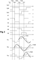
- Figure 6 is a graphic representing different protection criteria of the actuator of the figure 1 according to engine operating modes.
- Figure 7 is an electrical diagram of part of the actuator of the figure 1 , in which there is a protective element according to one embodiment of the invention.
- Figure 8 is a flowchart detailing the steps of a process for controlling and / or protecting the actuator of the figure 1 according to one embodiment of the invention.
- Figures 9 to 12 are graphs representing a method of determining the use of the first and second actuator protection criteria during the implementation of the control and / or protection method of the actuator. figure 6 .
- an actuator 1 of a mobile piece of equipment in a building such as a roller shutter or a fabric blind or with adjustable slats, or even a rolling gate, comprises an IPM power supply module connected to a DC voltage source + Vbus.
- the value of + Vbus is defined with respect to ground, or in other words to a reference voltage, Gnd.
- the actuator 1 further comprises a motor M of the type comprising a rotor and a stator.
- the motor M is of the electronically commutated brushless direct current type (or also called BLDC, acronym for the English expression BrushLess Direct Current).
- the stator of the motor M comprises three windings B1, B2, B3 supplied sequentially by the power supply module IPM, which generates a rotating electromagnetic field.
- the rotor not shown, includes permanent magnets oriented in the direction of the electromagnetic field.
- the motor M is furthermore provided with a first sensor Cp A and a second sensor Cp B arranged to determine the position of the rotor.
- the number of engine sensors making it possible to determine the position of the rotor is in no way limiting, and in particular can be three.
- the motor may also be devoid of sensors for determining the position of the rotor.
- the detection can be implemented by other measuring means, for example, by determining the electromotive force of the motor M.
- the control is preferably carried out in phase, but can also be carried out early or late, so as to create a motor torque.
- the IPM power supply module is provided with switches K1, K2, K3, K4, K5, K6, for example of the MOSFET type (acronym of the English term "Metal Oxide Semiconductor Field Effect Transistor ”).
- the power supply module IPM comprises the six switches K1, K2, K3, K4, K5, K6 of the MOSFET type in the same component.
- the arrangement of the switches of the power supply module may be different, and in particular these may be independent, or alternatively arranged in a configuration comprising three arms of two switches.
- switches of the power supply module may in particular be of the IGBT type (acronym of the English term “Insulated Gâte Bipolar Transistor”).
- the actuator 1 comprises a control and / or protection unit C provided with a digital processing unit Cnu.
- the digital processing unit Cnu is provided with a processor P comprising a system for regulating the speed of rotation of the motor M.
- the processor P is arranged to control the opening and closing of the switches K1, K2, K3, K4, K5, K6 so as to successively supply each winding B1, B2, B3 of the stator with electrical energy.
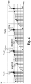
- Two of the switches K1, K2, K3, K4, K5, K6 are alternately driven as described in figures 2 and 3 .
- the driving of two of the switches K1, K2, K3, K4, K5, K6 corresponds to a command sequence, the change of two of the switches K1, K2, K3, K4, K5, K6 being driven is called a command change.
- control sequences are separated by control changes which correspond to transitions between a first sequence during which a first pair of switches K1, K2, K3, K4, K5, K6 is used and a second sequence during of which a second pair of switches K1, K2, K3, K4, K5, K6 is used.
- control sequences of two physical sensors Cp A, Cp B are shown.
- control sequence of a third sensor Cp C is shown.
- This third sensor Cp C is a virtual sensor whose signal is determined from the signals of the two physical sensors Cp A and Cp B.
- a third physical sensor could also be used instead of the virtual sensor Cp C.
- a command sequence is included between two command changes Tcc1, Tcc2, Tcc3, Tcc4, Tcc5, Tcc6, for example between Tcc1 and Tcc2.
- the piloting of two of the switches K1, K2, K3, K4, K5, K6 consists in keeping a first switch closed while the other is successively open and closed according to a PWM command (acronym of the English term “Pulse Width Modulation ”, or also called:“ pulse width modulation ”).
- switch K2 is controlled according to a pattern of successive openings and closings in PWM and switch K6 remains closed throughout the control sequence. It is then said that the switch K6 operates in full wave: it is electrically connected throughout the control sequence.
- the figure 3 does not differentiate the command sequences of switches K1, K2, K3, K4, K5, K6 according to a PWM configuration or a full wave configuration for the purpose of simplifying the figure, although these two configurations are carried out according to the diagram of the figure 2 .
- the digital processing unit Cnu comprises an input provided with an analog-to-digital converter ADC.
- the input provided with the analog-to-digital converter ADC is arranged to transmit a signal to the processor P from the signal which it receives.
- the actuator 1 further comprises a signal generator Can provided with a resistor Rs and an analog filter FL, for example produced in the form of a low-pass RC circuit, constituted for example by a resistor R167 and a C1 capacity represented on the figure 1 and the figure 7 .
- a signal generator Can provided with a resistor Rs and an analog filter FL, for example produced in the form of a low-pass RC circuit, constituted for example by a resistor R167 and a C1 capacity represented on the figure 1 and the figure 7 .
- the signal generator Can is arranged to deliver an instantaneous signal SI representative of the electric power supply supplied to the motor M, in particular of the current Is, to the input provided with the analog-to-digital converter ADC.
- the resistor Rs is placed between the power supply module IPM and the ground Gnd.
- the instantaneous signal SI representative of the electrical power supplied to the motor M is obtained from the current Is, and following the passage of the current Is in the signal generator Can.
- the voltage Vs and the current Is have the same shape as the instantaneous signal SI.
- the input provided with the analog-to-digital converter ADC indirectly reads an instantaneous value of the current Is.
- Pulse pulses of the instantaneous signal SI are increasing during the power supply of the same winding B1, B2, B3, in other words during a control sequence. Pulse pulses are represented by dots.
- the control sequences can be offset (late or early) with respect to the sensors Cp A, Cp B depending on the control mode.
- the sequences of the sensors Cp A, Cp B and control of the switches K1, K2, K3, K4, K5, K6 are in phase during the starting sequence then shifted once the motor M is rotating.
- the actuator 1 further comprises a polarization element PI arranged between the input provided with the analog-to-digital converter ADC and the analog filter FL.
- the polarization element PI is supplied by the same voltage source VDD as that of the processor P.
- the polarization element PI comprises a resistor R168.
- the figure 7 illustrates a specific aspect of the electronic circuit used, which can be implemented independently of the protection arrangements for actuator 1.
- a signal generator Can provided with a resistor Rs and an analog filter FL, for example produced in the form of a low-pass RC circuit, constituted for example by a resistor R167 and a capacitor C1.
- the signal generator Can thus formed is arranged to deliver an instantaneous signal SI representative of the electric power supply supplied to the motor M, and in particular of the current Is, to the input provided with the analog-to-digital converter ADC.
- the polarization element PI is arranged to deliver a default input signal when the instantaneous signal SI is not delivered to the input provided with the analog-to-digital converter ADC. Also, in normal operation when the signal generator Can supplies a signal, the polarization element PI has no influence on the measurement of the instantaneous signal SI.
- the input provided with the analog-to-digital converter ADC measures a signal which is a function of the voltage VDD.
- the measurement of the voltage VDD by the input of the analog-digital converter ADC corresponds to the detection of an operating anomaly of the engine M.
- the resistor R168 polarizes the input of the analog-to-digital converter ADC to the voltage VDD.
- a first step E1 consists in having an instantaneous signal SI representative of the electric power supply supplied to the motor M.
- the instantaneous signal SI is an image of the current Is.
- a second step E2 consists in carrying out a sampling of values of the instantaneous signal SI. As shown in figure 4 , the sampling represented by the points is synchronized with the pulses.
- sampling is carried out on each pulse pulse. According to variant embodiments, it would also be possible to carry out sampling on only part of the plurality of pulse pulses.
- Sampling in the middle of each pulse pulse aims to avoid measuring the disturbances of the instantaneous signal SI linked to the power switching.
- Sampling is a measurement of the value of the instantaneous signal SI carried out at the input of the analog-to-digital converter ADC.
- a first control step E3 according to a first criterion CRa of protection of the actuator 1 consists in carrying out a systematic control of each sampled value ECH.
- the comparison of the sampled value ECH is compared with the first protection criterion CRa of the actuator 1 before the next conversion.
- the sampled values ECH are thus checked on their reception at the input provided with the analog digital converter ADC according to a first criterion CRa of protection of the actuator 1. Once the check has been carried out, the last sampled value ECH and converted by the analog converter digital ADC is stored until the next conversion of a sampled value ECH.
- the analog-to-digital converter ADC sends a first anomaly information IAa, in particular to the processor P.
- the first criterion CRa for protecting the actuator 1 consists in comparing each sampled value ECH with a first threshold value VS1, the first anomaly item of information IAa being sent when the sampled value ECH is greater than the first threshold value VS1.
- the analog-to-digital converter ADC is therefore arranged to compare each sampled value ECH with the first threshold value VS1 and to send a first item of anomaly information IAa when the first threshold value VS1 is crossed by the sampled value ECH.
- a step of acquisition E3 ′ of a set of values ECHa among the sampled values ECH is carried out in parallel with the control step E3 according to the first criterion CRa of protection of the actuator 1, as illustrated in figure 8 .
- the acquisition step E3 ′ consists in acquiring a set of values ECHa from among the sampled values ECH and in determining a representative quantity GR from said set of sampled values acquired ECHa. This acquisition step E3 'is performed by the processor P.
- the acquisition consists, for the analog digital converter ADC, in transmitting the last sampled value ECH to the processor P, following the request of the processor P and before the change of command Tcc1, Tcc2, Tcc3, Tcc4, Tcc5, Tcc6 represented by an arrow.
- Tcc6 Carrying out this acquisition just before the change of command Tcc1, Tcc2, Tcc3, Tcc4, Tcc5, Tcc6 allows the processor P to more easily determine the value that must be transmitted by the analog-to-digital converter ADC to the processor P.
- Tcc6 is a value representative of the engine torque, just like the other sampled values ECH.
- the first value of a command sequence is difficult to use since it has a low value.
- ECH sampled values it would be necessary to determine one to be transmitted to the processor P for processing.
- this choice from among the sampled values ECH can only be made once the control sequence has ended, all of the values of the control sequence having been sampled. Additional steps should be provided for implementing additional memory storage, because once the control sequence is complete, the values converted by the ADC ADC are overwritten by the following values.
- This command sequence value is the last converted value just before the command change Tcc1, Tcc2, Tcc3, Tcc4, Tcc5, Tcc6.
- this value is more easily detectable because it has the highest level.
- the processor P then proceeds to determine the representative quantity GR from the set of values ECHa among the sampled values ECH. As the sampled values ECHa are acquired just before the change of command Tcc1, Tcc2, Tcc3, Tcc4, Tcc5, Tcc6, the processor P is regularly supplied with acquired sampled values ECHa.
- the processor P determines the representative quantity GR as being the sliding average of the last acquired sampled values ECHa, for example of the twelve last sampled values acquired ECHa.
- the newly acquired sampled values ECHa are added to the set of acquired sampled values ECHa and the oldest acquired sampled values ECHa are discarded as they go.
- a second step of checking E4 ′ of the representative quantity GR follows on from the acquisition step E3 ′, as illustrated in figure 8 .
- the second control step E4 ' is performed by the processor P.
- the control step E4 ′ of the representative quantity GR consists in carrying out a control of said representative quantity GR according to a second criterion CRb of protection of the actuator 1 and to send a second information of anomaly IAb, in particular to the processor P, if the representative quantity GR does not meet the second criterion CRb of protection of the actuator 1.
- the control according to the second criterion CRb of protection of the actuator 1 further comprises a comparison of a time evolution AND of the successively determined representative quantities GR with a threshold time variation ETS.
- the second anomaly item of information IAb transmitted comprises an indication signaling the exceeding of the threshold time change ETS.
- the verification of the second criterion CRb of protection of the actuator 1 also consists of a comparison of the representative quantity GR with a second threshold value VS2.
- the second anomaly information IAb is also sent when the representative quantity GR is greater than the second threshold value VS2.
- the second anomaly information IAb transmitted comprises an indication signaling the crossing of the second threshold value VS2.
- the second threshold value VS2 varies according to the operating modes of the engine M.
- the x-axis shows the operating modes of the engine M in chronological order from the start of the engine M.
- the first operating mode is the starting mode DEM, when the speed of rotation of the motor M starts from a zero value then increases to a determined speed of rotation.
- the processor P waits to receive so-called valid rotation speed information, and can optionally add a predetermined period of time, which may for example be of the order of 5 ms.
- the predetermined period of time added following receipt of the rotational speed information is in no way limiting, and may be different. Adding this predetermined period of time is intended to make the software more robust.
- the second operating mode is a TRA transition mode, the speed of rotation is maintained during this predetermined period TRA, which corresponds in the example presented to two turns of the rotor of the motor M.
- TRA the speed of rotation of the motor M is regulated around a predetermined speed of rotation, which may for example be of the order of 1000 revolutions per minute.
- the third operating mode is the REG regulation mode, the power supply supplied to the motor M is modified, in particular by the processor P, with the aim of reaching a set speed of rotation.
- the fourth operating mode is the stabilized operating mode STA. This can for example begin after a determined period following the start of the third operating mode. In the example presented, the fourth operating mode begins 300 ms after the start of the REG regulation mode. In another example, the fourth operating mode can begin following the achievement of the set speed of rotation.
- limit intensity values are shown on the ordinate.
- a first limit current I1 corresponds to a maximum admissible value of the current Is, the maximum admissible value relating to simultaneous conduction phenomena of two switches of the same arm of the IPM power supply module causing a short circuit of the power supply. may appear at switches K1, K2, K3, K4, K5, K6 for supplying electrical energy to windings B1, B2, B3 of motor M.
- a second limit current I2 corresponds to a maximum admissible value of the current Is after passing through the motor M which must not be exceeded so that the rotor magnets are not demagnetized.
- a third limit current I3 corresponds to a maximum value of the current Is for limiting the instantaneous torque delivered by the actuator 1.
- a fourth limit current I4 corresponds to an average limit operating current Is, beyond which the torque of the motor M is greater than the maximum torque admissible by the mechanical elements of the actuator 1.
- the processor P defines the first threshold value VS1 as being the lowest of the first three limit intensities I1, I2, I3.
- the first threshold value VS1 is therefore the third limit intensity I3, which corresponds to the portions in bold lines of the figure 6 .
- the second threshold value VS2 is defined as being the lowest limiting intensity, ie I4. Thus, during the regulation mode REG and the stabilized operating mode STA, the second threshold value VS2 is equal to the fourth limit current I4.
- the first threshold value VS1 is greater than the second threshold value VS2 and that the crossing or exceeding of the second threshold value VS2 is only taken into account from the regulation mode. REG.
- the first threshold value VS1 and the second threshold value VS2 are parameterizable data of the processor P. They could be equal, or else the second threshold value VS2 could be greater than the first threshold value VS1.
- the processor P is arranged to control the temporal evolution ET of the representative quantity GR in order to be able to detect the limit switches of actuator 1. It should be noted that the protection stops the motor M before the rotor is blocked.
- the limit switches of the actuator 1 correspond to the stops intended to signal either the open position of the roller shutter curtain, or the closed position of the roller shutter curtain.
- a functional limitation intensity FON of the couple has also been shown. This value is used by the speed control system of rotation of the motor M. When this intensity FON is reached, the processor P is designed to reduce the speed of rotation. In reaction, the current Is is liable to change. However, if there is an anomaly or a malfunction in the motor M, the current Is does not necessarily fall with the speed of rotation of the motor M. The processor P then detects an overshoot of the second threshold value VS2 in regulation mode REG or in STA stabilized operating mode.
- the figures 9 to 12 present an example illustrating a method for determining the use of the first and second protection criteria CRa, CRb of the actuator 1 during the implementation of the control and / or protection method.
- the voltage Vs has been shown as well as the quantities GR capable of being measured, namely the voltage V1 of the largest pulse, a period T1 between two imp pulses and a period T2 between two of the control changes Tcc1, Tcc2, Tcc3, Tcc4, Tcc5, Tcc6.
- the evolution of the representative quantity GR V1 of the voltage V1 has been shown over a long period T L , of the order of 10 seconds. It is possible to measure a value of the protection when switching off the engine M. By ensuring that this measurement has been carried out after a fairly long time, it is known that the stabilized operating mode STA has been reached. If the cut occurs during the period T L , the measured value therefore corresponds to the second threshold value VS2, and consequently to the checking of the second protection criterion CRb of the actuator 1.
- the cutoff voltage corresponds to the first threshold value VS1, and therefore to the control of the first protection criterion CRa of the actuator 1.
- the engine is cut off during the period of time T2 corresponding to the duration between two of the command changes Tcc1, Tcc2, Tcc3, Tcc4, Tcc5, Tcc6, this is the exceeding of another second threshold value VS2bis, and consequently to the control of the second protection criterion CRb of the actuator 1.
- the other second threshold value VS2bis can be different from the value of the second threshold value VS2, because an instantaneous value is checked between two of the command changes Tcc1, Tcc2, Tcc3, Tcc4, Tcc5, Tcc6 and not the representative quantity GR V1 .
- the invention is not limited to the sole embodiment of this method of controlling and / or protecting an engine, described above by way of example, it embraces on the contrary all the variant embodiments which fall within the subject of the claims.
Landscapes
- Engineering & Computer Science (AREA)
- Power Engineering (AREA)
- Control Of Electric Motors In General (AREA)
Claims (13)
- Verfahren zum Kontrollieren und/oder Schützen eines Aktuators (1) einer mobilen Ausrüstung eines Gebäudes, wobei der Aktuator (1) einen Motor (M), in der Art einen Rotor und einen Stator umfassend, umfasst, wobei das Verfahren die Schritte umfasst, die darin bestehen:- (E1) über ein sofortiges Signal (SI), das repräsentativ für die dem Motor (M) bereitgestellte Stromversorgung ist, zu verfügen, wobei das sofortige Signal (SI) eine Vielzahl von Impulsen (imp) aufweist,- (E2) ein Abtasten von Werten (ECH) des sofortigen Signals (SI) durchzuführen, wobei das Abtasten mit mindestens einem Teil der Impulse (imp) der Vielzahl von Impulsen (imp) des sofortigen Signals (SI) synchronisiert wird,- (E3) eine Kontrolle jedes abgetasteten Werts (ECH) gemäß einem ersten Schutzkriterium (CRa) des Aktuators (1) durchzuführen, und eine erste Information einer Anomalie (IAa) für jeden abgetasteten Wert (ECH) auszugeben, der das erste Schutzkriterium (CRa) nicht erfüllt,- (E3') eine Gesamtheit von Werten (ECHa) aus den abgetasteten Werten (ECH) zu erfassen,- (E4') eine Kontrolle gemäß einem zweiten Schutzkriterium (CRb) des Aktuators (1) durchzuführen, der auf die Gesamtheit von erfassten abgetasteten Werten (ECHa) angewandt wird, und eine zweite Information einer Anomalie (IAb) für die Gesamtheit von erfassten abgetasteten Werten (ECH) auszugeben, die das zweite Schutzkriterium (CRb) nicht erfüllen.
- Verfahren zum Kontrollieren und/oder Schützen nach Anspruch 1, wobei der Motor (M) mindestens einen Betriebsmodus, insbesondere einen Startmodus (DEM) des Motors (M), und einen zweiten Betriebsmodus, insbesondere einen stabilisierten Betriebsmodus (STA) aufweist, und wobei das erste Schutzkriterium (CRa) und/oder das zweite Schutzkriterium (CRb) des Aktuators (1) in Abhängigkeit von dem Betriebsmodus des Motors (M) geändert wird.
- Verfahren zum Kontrollieren und/oder Schützen nach einem der vorstehenden Ansprüche, wobei eine repräsentative Größe (GR) aus der Gesamtheit von erfassten abgetasteten Werten (ECHa) bestimmt wird, und das zweite Schutzkriterium (CRb) des Aktuators (1) auf die repräsentative Größe (GR) angewandt wird.
- Verfahren zum Kontrollieren und/oder Schützen nach Anspruch 3, wobei beim Schritt (E3') zum Erfassen und Bestimmen der repräsentativen Größe (GR) ein später als die erfassten abgetasteten Werte (ECHa) erfasster abgetasteter Wert (ECHa) zur Gesamtheit von erfassten abgetasteten Werten (ECHa) hinzugefügt wird, wobei die repräsentative Größe (GR) nach dem Hinzufügen des später erfassten abgetasteten Wertes (ECHa) erneut bestimmt wird.
- Verfahren zum Kontrollieren und/oder Schützen nach Anspruch 4, wobei beim Hinzufügen des später erfassten abgetasteten Wertes (ECHa) der älteste erfasste abgetastete Wert (ECHa) aus der Gesamtheit von erfassten abgetasteten Werten (ECHa) gelöscht wird.
- Verfahren zum Kontrollieren und/oder Schützen nach Anspruch 4 oder Anspruch 5, wobei die Kontrolle gemäß dem zweiten Schutzkriterium (CRb) des Aktuators (1) weiter einen Vergleich einer zeitlichen Entwicklung (ET) der nacheinander bestimmten repräsentativen Größen (GR) mit einer zeitlichen Schwellenentwicklung (ETS) umfasst.
- Verfahren zum Kontrollieren und/oder Schützen nach einem der vorstehenden Ansprüche, wobei die Kontrolle gemäß dem ersten Schutzkriterium (CRa) des Aktuators (1) einen Vergleich jedes abgetasteten Werts (ECH) mit einem ersten Schwellenwert (VS1) umfasst.
- Verfahren zum Kontrollieren und/oder Schützen nach Anspruch 7, in Kombination mit einem der Ansprüche 3 bis 6, wobei die Kontrolle gemäß dem zweiten Schutzkriterium (CRb) des Aktuators (1) einen Vergleich der repräsentativen Größe (GR) mit einem zweiten Schwellenwert (VS2) umfasst.
- Computerprogrammprodukt, Codeanweisungen, die ausgeführt sind, um die Schritte eines Verfahrens zum Kontrollieren und/oder Schützen nach einem der vorstehenden Ansprüche umzusetzen, umfassend, wenn das Programm auf einem Prozessor (P) einer Einheit zum Kontrollieren und/oder Schützen (C) ausgeführt wird.
- Einheit zum Kontrollieren und/oder Schützen (C), die mit einem Prozessor (P) versehen ist, der im Speicher die Codeanweisungen eines Computerprogrammprodukts nach Anspruch 9 umfasst, wobei die Einheit zum Kontrollieren und/oder Schützen (C) ausgeführt ist, um ein sofortiges Signal (SI) zu lesen, das repräsentativ für die einem Motor (M), in der Art einen Rotor und einen Stator umfassend, bereitgestellte Stromversorgung ist.
- Einheit zum Kontrollieren und/oder Schützen (C) nach Anspruch 10, weiter einen Signalgenerator (Can) umfassend, der ausgeführt ist, um ein sofortiges Signal (SI), das repräsentativ für die einem Motor (M) bereitgestellte Stromversorgung ist, zu erstellen, und ein Polarisationselement (PI), das ausgeführt ist, um ein standardgemäßes Eingangssignal anstelle des sofortigen Signals (SI) festzulegen, wenn der Signalgenerator (Can) einen Fehler aufweist, der zur Abwesenheit des Signals (SI) führt.
- Einheit zum Kontrollieren und/oder Schützen (C) nach Anspruch 10 oder Anspruch 11, umfassend eine digitale Verarbeitungseinheit (Cnu), beispielsweise einen Mikro-Controller, wobei die digitale Verarbeitungseinheit (Cnu) den Prozessor (P) und einen Analog-Digital-Wandler (ADC) umfasst, der ausgeführt ist, um das sofortige Signal (SI), das repräsentativ für die einem Motor (M) bereitgestellte Stromversorgung ist, zu lesen und in ein durch den Prozessor (P) interpretierbares digitales Signal umzuwandeln.
- Aktuator (1) einer mobilen Ausrüstung eines Gebäudes, Folgendes umfassend:- einen Motor (M) in der Art einen Rotor und einen Stator umfassend,- ein Versorgungsmodul (IPM), das ausgeführt ist, um dem Motor (M) eine Stromversorgung bereitzustellen,- eine Einheit zum Kontrollieren und/oder Schützen (C) nach einem der Ansprüche 10 bis 12, ausgeführt, um ein sofortiges Signal (SI) zu lesen, das repräsentativ für die einem Motor (M) bereitgestellte Stromversorgung ist.
Applications Claiming Priority (2)
| Application Number | Priority Date | Filing Date | Title |
|---|---|---|---|
| FR1457176A FR3024304B1 (fr) | 2014-07-25 | 2014-07-25 | Procede et unite de controle et/ou de protection d’un actionneur d’un equipement mobile d’un batiment |
| PCT/FR2015/051969 WO2016012702A1 (fr) | 2014-07-25 | 2015-07-17 | Procédé et unité de contrôle et/ou de protection d'un actionneur d'un équipement mobile d'un bâtiment |
Publications (2)
| Publication Number | Publication Date |
|---|---|
| EP3172832A1 EP3172832A1 (de) | 2017-05-31 |
| EP3172832B1 true EP3172832B1 (de) | 2020-07-22 |
Family
ID=51830501
Family Applications (1)
| Application Number | Title | Priority Date | Filing Date |
|---|---|---|---|
| EP15753118.7A Active EP3172832B1 (de) | 2014-07-25 | 2015-07-17 | Verfahren und einheit zum steuern und/oder schützen eines aktuators eines teils einer mobilen ausrüstung eines gebäudes |
Country Status (4)
| Country | Link |
|---|---|
| US (1) | US9991840B2 (de) |
| EP (1) | EP3172832B1 (de) |
| FR (1) | FR3024304B1 (de) |
| WO (1) | WO2016012702A1 (de) |
Families Citing this family (1)
| Publication number | Priority date | Publication date | Assignee | Title |
|---|---|---|---|---|
| CN111464110B (zh) * | 2019-01-21 | 2021-09-21 | 广东美的制冷设备有限公司 | 电机驱动控制模组、压缩机及空调器 |
Family Cites Families (7)
| Publication number | Priority date | Publication date | Assignee | Title |
|---|---|---|---|---|
| FR2714234B1 (fr) * | 1993-12-16 | 1996-08-23 | Telemecanique | Système de contrôle d'alimentation d'un moteur asynchrone. |
| JP3763415B1 (ja) * | 2005-07-26 | 2006-04-05 | Tdk株式会社 | 平均電流検出回路 |
| JP4441735B2 (ja) * | 2006-09-08 | 2010-03-31 | 有限会社 ソフトロックス | サイクル運転加工機の加工工程の監視方法 |
| DE102006052042A1 (de) * | 2006-10-30 | 2008-05-15 | Bombardier Transportation Gmbh | Steuerung und/oder Regelung eines 3-Phasen-Stromrichters für den Betrieb einer Asynchronmaschine |
| US7554473B2 (en) * | 2007-05-02 | 2009-06-30 | Cirrus Logic, Inc. | Control system using a nonlinear delta-sigma modulator with nonlinear process modeling |
| CN100557943C (zh) * | 2008-06-13 | 2009-11-04 | 株洲南车时代电气股份有限公司 | 一种基于空间矢量的同步调制方法 |
| US9151802B2 (en) * | 2011-04-15 | 2015-10-06 | Schweitzer Engineering Laboratories, Inc. | Detection of broken rotor bar conditions in a motor using maximum current magnitude and average current magnitude |
-
2014
- 2014-07-25 FR FR1457176A patent/FR3024304B1/fr not_active Expired - Fee Related
-
2015
- 2015-07-17 EP EP15753118.7A patent/EP3172832B1/de active Active
- 2015-07-17 US US15/328,894 patent/US9991840B2/en active Active
- 2015-07-17 WO PCT/FR2015/051969 patent/WO2016012702A1/fr active Application Filing
Non-Patent Citations (1)
| Title |
|---|
| None * |
Also Published As
| Publication number | Publication date |
|---|---|
| US20170222593A1 (en) | 2017-08-03 |
| EP3172832A1 (de) | 2017-05-31 |
| WO2016012702A1 (fr) | 2016-01-28 |
| US9991840B2 (en) | 2018-06-05 |
| FR3024304B1 (fr) | 2018-03-02 |
| FR3024304A1 (fr) | 2016-01-29 |
Similar Documents
| Publication | Publication Date | Title |
|---|---|---|
| EP2849196B1 (de) | Verfahren zur Erkennung der Ursache eines Spannungsverlusts vor einem Trennschalter, Hilfsgerät für Trennschalter sowie elektrisches System, das einen solchen Trennschalter und ein solches Hilfsgerät umfasst | |
| FR2962270A1 (fr) | Machine électrique tournante améliorée pour assurer une protection contre les coupures d'alimentation électrique | |
| FR2785106A1 (fr) | Procede et dispositif pour detecter la vitesse de rotation d'un moteur a courant continu commande par un signal a modulation de largeur d'impulsions | |
| EP2849195B1 (de) | Zusatzvorrichung für elektrischen Schutzschalter, elektrisches System mit einem Schutzschalter und dieser Zusatzvorrichtung und Verfahren zur Bestimmung des Grunds der Öffnung des Schutzshalters dank dieser Zusatzvorrichtung | |
| EP1729408B1 (de) | Betätiger und Betriebsverfahren dafür | |
| EP3172832B1 (de) | Verfahren und einheit zum steuern und/oder schützen eines aktuators eines teils einer mobilen ausrüstung eines gebäudes | |
| EP3171231B1 (de) | Stossdetektorschaltkreis und sein funktionsverfahren | |
| EP0120723B1 (de) | Verfahren und Vorrichtung zur Feststellung der Geschwindigkeitsverminderung eines Gleichstrommotors sowie Motor mit einer derartigen Vorrichtung | |
| EP3167543B1 (de) | Verfahren zur erzeugung von steuersignalen zur verwaltung des betriebs eines synchronmotors, steuerungsvorrichtung und aktuator | |
| EP0744679A1 (de) | Elektronisches Steuerungsverfahren zum Öffnen und/oder Schliessen einer Tür und Gerät dafür | |
| FR3080919A1 (fr) | Procede de determination d'un courant estime d'un moteur electrique triphase en mode degrade | |
| EP0965724A1 (de) | Antriebsvorrichtung einer in zwei Richtungen drehbaren rohrförmigen Walze, Rolladenwalze mit einer derartigen Antriebsvorrichtung, Rolladen mit einer derartigen Walze | |
| EP3722891B1 (de) | Verfahren und system zur bestimmung eines fehlers und der korrektur der winkelposition eines kontinuierlich drehenden motors | |
| EP2937987A2 (de) | Steuerverfahren und -vorrichtung für progressives anlasssystem eines motors, das ein mass der stromvariante nutzt | |
| EP3121366B1 (de) | Verfahren zur erkennung der bewegungsrichtung einer verdunkelungsblende | |
| FR2908246A1 (fr) | Moteur electrique a courant continu et procede de controle de la position angulaire d'un tel moteur | |
| FR2663473A1 (fr) | Dispositif et procede de limitation de charge pour appareil mecanique ou similaire, utilisant au moins un organe moteur de type electrique. | |
| FR3093814A1 (fr) | Installation electrique comportant un module de surveillance | |
| EP0736961A1 (de) | Vorrichtung zur Winkelregelung eines Schrittmotors | |
| FR3083319A1 (fr) | Compteur electrique comportant un organe de coupure auxiliaire agence pour raccorder selectivement un equipement d’une installation au reseau electrique | |
| FR2809242A1 (fr) | Systeme de detection de la position de fin de course d'une piece mobile par detection du courant de blocage | |
| EP3121365B1 (de) | Verfahren zur erkennung der bewegungsrichtung einer verdunkelungsblende | |
| WO2015022280A1 (fr) | Procédé, dispositif et programme d'ordinateur pour la commande d'un disjoncteur mécatronique | |
| WO2021155987A1 (fr) | Procédé d'identification de dysfonctionnement d'un ensemble onduleur-moteur | |
| EP3938793A1 (de) | Elektrische anlage mit einem überwachungsmodul |
Legal Events
| Date | Code | Title | Description |
|---|---|---|---|
| STAA | Information on the status of an ep patent application or granted ep patent |
Free format text: STATUS: THE INTERNATIONAL PUBLICATION HAS BEEN MADE |
|
| PUAI | Public reference made under article 153(3) epc to a published international application that has entered the european phase |
Free format text: ORIGINAL CODE: 0009012 |
|
| STAA | Information on the status of an ep patent application or granted ep patent |
Free format text: STATUS: REQUEST FOR EXAMINATION WAS MADE |
|
| 17P | Request for examination filed |
Effective date: 20170104 |
|
| AK | Designated contracting states |
Kind code of ref document: A1 Designated state(s): AL AT BE BG CH CY CZ DE DK EE ES FI FR GB GR HR HU IE IS IT LI LT LU LV MC MK MT NL NO PL PT RO RS SE SI SK SM TR |
|
| AX | Request for extension of the european patent |
Extension state: BA ME |
|
| DAV | Request for validation of the european patent (deleted) | ||
| DAX | Request for extension of the european patent (deleted) | ||
| REG | Reference to a national code |
Ref country code: DE Ref legal event code: R079 Ref document number: 602015056160 Country of ref document: DE Free format text: PREVIOUS MAIN CLASS: H02P0029020000 Ipc: H02P0029024000 |
|
| GRAP | Despatch of communication of intention to grant a patent |
Free format text: ORIGINAL CODE: EPIDOSNIGR1 |
|
| STAA | Information on the status of an ep patent application or granted ep patent |
Free format text: STATUS: GRANT OF PATENT IS INTENDED |
|
| RIC1 | Information provided on ipc code assigned before grant |
Ipc: H02P 29/024 20160101AFI20200203BHEP |
|
| GRAS | Grant fee paid |
Free format text: ORIGINAL CODE: EPIDOSNIGR3 |
|
| INTG | Intention to grant announced |
Effective date: 20200309 |
|
| RAP1 | Party data changed (applicant data changed or rights of an application transferred) |
Owner name: SOMFY ACTIVITES SA |
|
| GRAA | (expected) grant |
Free format text: ORIGINAL CODE: 0009210 |
|
| STAA | Information on the status of an ep patent application or granted ep patent |
Free format text: STATUS: THE PATENT HAS BEEN GRANTED |
|
| AK | Designated contracting states |
Kind code of ref document: B1 Designated state(s): AL AT BE BG CH CY CZ DE DK EE ES FI FR GB GR HR HU IE IS IT LI LT LU LV MC MK MT NL NO PL PT RO RS SE SI SK SM TR |
|
| REG | Reference to a national code |
Ref country code: GB Ref legal event code: FG4D Free format text: NOT ENGLISH |
|
| REG | Reference to a national code |
Ref country code: CH Ref legal event code: EP |
|
| REG | Reference to a national code |
Ref country code: DE Ref legal event code: R096 Ref document number: 602015056160 Country of ref document: DE |
|
| REG | Reference to a national code |
Ref country code: AT Ref legal event code: REF Ref document number: 1294342 Country of ref document: AT Kind code of ref document: T Effective date: 20200815 |
|
| REG | Reference to a national code |
Ref country code: IE Ref legal event code: FG4D Free format text: LANGUAGE OF EP DOCUMENT: FRENCH |
|
| REG | Reference to a national code |
Ref country code: LT Ref legal event code: MG4D |
|
| REG | Reference to a national code |
Ref country code: AT Ref legal event code: MK05 Ref document number: 1294342 Country of ref document: AT Kind code of ref document: T Effective date: 20200722 |
|
| PG25 | Lapsed in a contracting state [announced via postgrant information from national office to epo] |
Ref country code: NO Free format text: LAPSE BECAUSE OF FAILURE TO SUBMIT A TRANSLATION OF THE DESCRIPTION OR TO PAY THE FEE WITHIN THE PRESCRIBED TIME-LIMIT Effective date: 20201022 Ref country code: ES Free format text: LAPSE BECAUSE OF FAILURE TO SUBMIT A TRANSLATION OF THE DESCRIPTION OR TO PAY THE FEE WITHIN THE PRESCRIBED TIME-LIMIT Effective date: 20200722 Ref country code: GR Free format text: LAPSE BECAUSE OF FAILURE TO SUBMIT A TRANSLATION OF THE DESCRIPTION OR TO PAY THE FEE WITHIN THE PRESCRIBED TIME-LIMIT Effective date: 20201023 Ref country code: AT Free format text: LAPSE BECAUSE OF FAILURE TO SUBMIT A TRANSLATION OF THE DESCRIPTION OR TO PAY THE FEE WITHIN THE PRESCRIBED TIME-LIMIT Effective date: 20200722 Ref country code: LT Free format text: LAPSE BECAUSE OF FAILURE TO SUBMIT A TRANSLATION OF THE DESCRIPTION OR TO PAY THE FEE WITHIN THE PRESCRIBED TIME-LIMIT Effective date: 20200722 Ref country code: BG Free format text: LAPSE BECAUSE OF FAILURE TO SUBMIT A TRANSLATION OF THE DESCRIPTION OR TO PAY THE FEE WITHIN THE PRESCRIBED TIME-LIMIT Effective date: 20201022 Ref country code: PT Free format text: LAPSE BECAUSE OF FAILURE TO SUBMIT A TRANSLATION OF THE DESCRIPTION OR TO PAY THE FEE WITHIN THE PRESCRIBED TIME-LIMIT Effective date: 20201123 Ref country code: FI Free format text: LAPSE BECAUSE OF FAILURE TO SUBMIT A TRANSLATION OF THE DESCRIPTION OR TO PAY THE FEE WITHIN THE PRESCRIBED TIME-LIMIT Effective date: 20200722 Ref country code: HR Free format text: LAPSE BECAUSE OF FAILURE TO SUBMIT A TRANSLATION OF THE DESCRIPTION OR TO PAY THE FEE WITHIN THE PRESCRIBED TIME-LIMIT Effective date: 20200722 Ref country code: SE Free format text: LAPSE BECAUSE OF FAILURE TO SUBMIT A TRANSLATION OF THE DESCRIPTION OR TO PAY THE FEE WITHIN THE PRESCRIBED TIME-LIMIT Effective date: 20200722 |
|
| PG25 | Lapsed in a contracting state [announced via postgrant information from national office to epo] |
Ref country code: LV Free format text: LAPSE BECAUSE OF FAILURE TO SUBMIT A TRANSLATION OF THE DESCRIPTION OR TO PAY THE FEE WITHIN THE PRESCRIBED TIME-LIMIT Effective date: 20200722 Ref country code: RS Free format text: LAPSE BECAUSE OF FAILURE TO SUBMIT A TRANSLATION OF THE DESCRIPTION OR TO PAY THE FEE WITHIN THE PRESCRIBED TIME-LIMIT Effective date: 20200722 Ref country code: IS Free format text: LAPSE BECAUSE OF FAILURE TO SUBMIT A TRANSLATION OF THE DESCRIPTION OR TO PAY THE FEE WITHIN THE PRESCRIBED TIME-LIMIT Effective date: 20201122 |
|
| PG25 | Lapsed in a contracting state [announced via postgrant information from national office to epo] |
Ref country code: NL Free format text: LAPSE BECAUSE OF FAILURE TO SUBMIT A TRANSLATION OF THE DESCRIPTION OR TO PAY THE FEE WITHIN THE PRESCRIBED TIME-LIMIT Effective date: 20200722 |
|
| REG | Reference to a national code |
Ref country code: DE Ref legal event code: R097 Ref document number: 602015056160 Country of ref document: DE |
|
| PG25 | Lapsed in a contracting state [announced via postgrant information from national office to epo] |
Ref country code: DK Free format text: LAPSE BECAUSE OF FAILURE TO SUBMIT A TRANSLATION OF THE DESCRIPTION OR TO PAY THE FEE WITHIN THE PRESCRIBED TIME-LIMIT Effective date: 20200722 Ref country code: CZ Free format text: LAPSE BECAUSE OF FAILURE TO SUBMIT A TRANSLATION OF THE DESCRIPTION OR TO PAY THE FEE WITHIN THE PRESCRIBED TIME-LIMIT Effective date: 20200722 Ref country code: IT Free format text: LAPSE BECAUSE OF FAILURE TO SUBMIT A TRANSLATION OF THE DESCRIPTION OR TO PAY THE FEE WITHIN THE PRESCRIBED TIME-LIMIT Effective date: 20200722 Ref country code: RO Free format text: LAPSE BECAUSE OF FAILURE TO SUBMIT A TRANSLATION OF THE DESCRIPTION OR TO PAY THE FEE WITHIN THE PRESCRIBED TIME-LIMIT Effective date: 20200722 Ref country code: SM Free format text: LAPSE BECAUSE OF FAILURE TO SUBMIT A TRANSLATION OF THE DESCRIPTION OR TO PAY THE FEE WITHIN THE PRESCRIBED TIME-LIMIT Effective date: 20200722 Ref country code: EE Free format text: LAPSE BECAUSE OF FAILURE TO SUBMIT A TRANSLATION OF THE DESCRIPTION OR TO PAY THE FEE WITHIN THE PRESCRIBED TIME-LIMIT Effective date: 20200722 |
|
| PLBE | No opposition filed within time limit |
Free format text: ORIGINAL CODE: 0009261 |
|
| STAA | Information on the status of an ep patent application or granted ep patent |
Free format text: STATUS: NO OPPOSITION FILED WITHIN TIME LIMIT |
|
| PG25 | Lapsed in a contracting state [announced via postgrant information from national office to epo] |
Ref country code: AL Free format text: LAPSE BECAUSE OF FAILURE TO SUBMIT A TRANSLATION OF THE DESCRIPTION OR TO PAY THE FEE WITHIN THE PRESCRIBED TIME-LIMIT Effective date: 20200722 |
|
| 26N | No opposition filed |
Effective date: 20210423 |
|
| PG25 | Lapsed in a contracting state [announced via postgrant information from national office to epo] |
Ref country code: SK Free format text: LAPSE BECAUSE OF FAILURE TO SUBMIT A TRANSLATION OF THE DESCRIPTION OR TO PAY THE FEE WITHIN THE PRESCRIBED TIME-LIMIT Effective date: 20200722 |
|
| PG25 | Lapsed in a contracting state [announced via postgrant information from national office to epo] |
Ref country code: SI Free format text: LAPSE BECAUSE OF FAILURE TO SUBMIT A TRANSLATION OF THE DESCRIPTION OR TO PAY THE FEE WITHIN THE PRESCRIBED TIME-LIMIT Effective date: 20200722 |
|
| REG | Reference to a national code |
Ref country code: NL Ref legal event code: MP Effective date: 20200722 |
|
| REG | Reference to a national code |
Ref country code: CH Ref legal event code: PL |
|
| PG25 | Lapsed in a contracting state [announced via postgrant information from national office to epo] |
Ref country code: MC Free format text: LAPSE BECAUSE OF FAILURE TO SUBMIT A TRANSLATION OF THE DESCRIPTION OR TO PAY THE FEE WITHIN THE PRESCRIBED TIME-LIMIT Effective date: 20200722 |
|
| REG | Reference to a national code |
Ref country code: BE Ref legal event code: MM Effective date: 20210731 |
|
| PG25 | Lapsed in a contracting state [announced via postgrant information from national office to epo] |
Ref country code: LI Free format text: LAPSE BECAUSE OF NON-PAYMENT OF DUE FEES Effective date: 20210731 Ref country code: CH Free format text: LAPSE BECAUSE OF NON-PAYMENT OF DUE FEES Effective date: 20210731 |
|
| PG25 | Lapsed in a contracting state [announced via postgrant information from national office to epo] |
Ref country code: LU Free format text: LAPSE BECAUSE OF NON-PAYMENT OF DUE FEES Effective date: 20210717 |
|
| PG25 | Lapsed in a contracting state [announced via postgrant information from national office to epo] |
Ref country code: IE Free format text: LAPSE BECAUSE OF NON-PAYMENT OF DUE FEES Effective date: 20210717 Ref country code: BE Free format text: LAPSE BECAUSE OF NON-PAYMENT OF DUE FEES Effective date: 20210731 |
|
| PG25 | Lapsed in a contracting state [announced via postgrant information from national office to epo] |
Ref country code: HU Free format text: LAPSE BECAUSE OF FAILURE TO SUBMIT A TRANSLATION OF THE DESCRIPTION OR TO PAY THE FEE WITHIN THE PRESCRIBED TIME-LIMIT; INVALID AB INITIO Effective date: 20150717 |
|
| PG25 | Lapsed in a contracting state [announced via postgrant information from national office to epo] |
Ref country code: CY Free format text: LAPSE BECAUSE OF FAILURE TO SUBMIT A TRANSLATION OF THE DESCRIPTION OR TO PAY THE FEE WITHIN THE PRESCRIBED TIME-LIMIT Effective date: 20200722 |
|
| PGFP | Annual fee paid to national office [announced via postgrant information from national office to epo] |
Ref country code: PL Payment date: 20230626 Year of fee payment: 9 |
|
| PGFP | Annual fee paid to national office [announced via postgrant information from national office to epo] |
Ref country code: GB Payment date: 20230713 Year of fee payment: 9 |
|
| PGFP | Annual fee paid to national office [announced via postgrant information from national office to epo] |
Ref country code: DE Payment date: 20230526 Year of fee payment: 9 |
|
| PG25 | Lapsed in a contracting state [announced via postgrant information from national office to epo] |
Ref country code: MK Free format text: LAPSE BECAUSE OF FAILURE TO SUBMIT A TRANSLATION OF THE DESCRIPTION OR TO PAY THE FEE WITHIN THE PRESCRIBED TIME-LIMIT Effective date: 20200722 |
|
| PG25 | Lapsed in a contracting state [announced via postgrant information from national office to epo] |
Ref country code: TR Free format text: LAPSE BECAUSE OF FAILURE TO SUBMIT A TRANSLATION OF THE DESCRIPTION OR TO PAY THE FEE WITHIN THE PRESCRIBED TIME-LIMIT Effective date: 20200722 |
|
| PGFP | Annual fee paid to national office [announced via postgrant information from national office to epo] |
Ref country code: FR Payment date: 20240521 Year of fee payment: 10 |