EP4039655B1 - Reaktor, der die kontinuierliche filtration einer durch einen filter fliessenden flüssigkeit ermöglicht und eine elektrochemische regeneration des filters in situ umfasst - Google Patents
Reaktor, der die kontinuierliche filtration einer durch einen filter fliessenden flüssigkeit ermöglicht und eine elektrochemische regeneration des filters in situ umfasst Download PDFInfo
- Publication number
- EP4039655B1 EP4039655B1 EP22154591.6A EP22154591A EP4039655B1 EP 4039655 B1 EP4039655 B1 EP 4039655B1 EP 22154591 A EP22154591 A EP 22154591A EP 4039655 B1 EP4039655 B1 EP 4039655B1
- Authority
- EP
- European Patent Office
- Prior art keywords
- anode
- filter
- reactor
- fluid
- electrolysis
- Prior art date
- Legal status (The legal status is an assumption and is not a legal conclusion. Google has not performed a legal analysis and makes no representation as to the accuracy of the status listed.)
- Active
Links
Images


Classifications
-
- C—CHEMISTRY; METALLURGY
- C02—TREATMENT OF WATER, WASTE WATER, SEWAGE, OR SLUDGE
- C02F—TREATMENT OF WATER, WASTE WATER, SEWAGE, OR SLUDGE
- C02F1/00—Treatment of water, waste water, or sewage
- C02F1/28—Treatment of water, waste water, or sewage by sorption
- C02F1/283—Treatment of water, waste water, or sewage by sorption using coal, charred products, or inorganic mixtures containing them
-
- B—PERFORMING OPERATIONS; TRANSPORTING
- B01—PHYSICAL OR CHEMICAL PROCESSES OR APPARATUS IN GENERAL
- B01J—CHEMICAL OR PHYSICAL PROCESSES, e.g. CATALYSIS OR COLLOID CHEMISTRY; THEIR RELEVANT APPARATUS
- B01J20/00—Solid sorbent compositions or filter aid compositions; Sorbents for chromatography; Processes for preparing, regenerating or reactivating thereof
- B01J20/02—Solid sorbent compositions or filter aid compositions; Sorbents for chromatography; Processes for preparing, regenerating or reactivating thereof comprising inorganic material
- B01J20/20—Solid sorbent compositions or filter aid compositions; Sorbents for chromatography; Processes for preparing, regenerating or reactivating thereof comprising inorganic material comprising free carbon; comprising carbon obtained by carbonising processes
-
- B—PERFORMING OPERATIONS; TRANSPORTING
- B01—PHYSICAL OR CHEMICAL PROCESSES OR APPARATUS IN GENERAL
- B01J—CHEMICAL OR PHYSICAL PROCESSES, e.g. CATALYSIS OR COLLOID CHEMISTRY; THEIR RELEVANT APPARATUS
- B01J20/00—Solid sorbent compositions or filter aid compositions; Sorbents for chromatography; Processes for preparing, regenerating or reactivating thereof
- B01J20/28—Solid sorbent compositions or filter aid compositions; Sorbents for chromatography; Processes for preparing, regenerating or reactivating thereof characterised by their form or physical properties
- B01J20/28014—Solid sorbent compositions or filter aid compositions; Sorbents for chromatography; Processes for preparing, regenerating or reactivating thereof characterised by their form or physical properties characterised by their form
- B01J20/28033—Membrane, sheet, cloth, pad, lamellar or mat
-
- B—PERFORMING OPERATIONS; TRANSPORTING
- B01—PHYSICAL OR CHEMICAL PROCESSES OR APPARATUS IN GENERAL
- B01J—CHEMICAL OR PHYSICAL PROCESSES, e.g. CATALYSIS OR COLLOID CHEMISTRY; THEIR RELEVANT APPARATUS
- B01J20/00—Solid sorbent compositions or filter aid compositions; Sorbents for chromatography; Processes for preparing, regenerating or reactivating thereof
- B01J20/28—Solid sorbent compositions or filter aid compositions; Sorbents for chromatography; Processes for preparing, regenerating or reactivating thereof characterised by their form or physical properties
- B01J20/28054—Solid sorbent compositions or filter aid compositions; Sorbents for chromatography; Processes for preparing, regenerating or reactivating thereof characterised by their form or physical properties characterised by their surface properties or porosity
- B01J20/28057—Surface area, e.g. B.E.T specific surface area
-
- B—PERFORMING OPERATIONS; TRANSPORTING
- B01—PHYSICAL OR CHEMICAL PROCESSES OR APPARATUS IN GENERAL
- B01J—CHEMICAL OR PHYSICAL PROCESSES, e.g. CATALYSIS OR COLLOID CHEMISTRY; THEIR RELEVANT APPARATUS
- B01J20/00—Solid sorbent compositions or filter aid compositions; Sorbents for chromatography; Processes for preparing, regenerating or reactivating thereof
- B01J20/28—Solid sorbent compositions or filter aid compositions; Sorbents for chromatography; Processes for preparing, regenerating or reactivating thereof characterised by their form or physical properties
- B01J20/28054—Solid sorbent compositions or filter aid compositions; Sorbents for chromatography; Processes for preparing, regenerating or reactivating thereof characterised by their form or physical properties characterised by their surface properties or porosity
- B01J20/28078—Pore diameter
- B01J20/2808—Pore diameter being less than 2 nm, i.e. micropores or nanopores
-
- B—PERFORMING OPERATIONS; TRANSPORTING
- B01—PHYSICAL OR CHEMICAL PROCESSES OR APPARATUS IN GENERAL
- B01J—CHEMICAL OR PHYSICAL PROCESSES, e.g. CATALYSIS OR COLLOID CHEMISTRY; THEIR RELEVANT APPARATUS
- B01J20/00—Solid sorbent compositions or filter aid compositions; Sorbents for chromatography; Processes for preparing, regenerating or reactivating thereof
- B01J20/28—Solid sorbent compositions or filter aid compositions; Sorbents for chromatography; Processes for preparing, regenerating or reactivating thereof characterised by their form or physical properties
- B01J20/28054—Solid sorbent compositions or filter aid compositions; Sorbents for chromatography; Processes for preparing, regenerating or reactivating thereof characterised by their form or physical properties characterised by their surface properties or porosity
- B01J20/28088—Pore-size distribution
-
- B—PERFORMING OPERATIONS; TRANSPORTING
- B01—PHYSICAL OR CHEMICAL PROCESSES OR APPARATUS IN GENERAL
- B01J—CHEMICAL OR PHYSICAL PROCESSES, e.g. CATALYSIS OR COLLOID CHEMISTRY; THEIR RELEVANT APPARATUS
- B01J20/00—Solid sorbent compositions or filter aid compositions; Sorbents for chromatography; Processes for preparing, regenerating or reactivating thereof
- B01J20/30—Processes for preparing, regenerating, or reactivating
- B01J20/34—Regenerating or reactivating
- B01J20/3416—Regenerating or reactivating of sorbents or filter aids comprising free carbon, e.g. activated carbon
-
- B—PERFORMING OPERATIONS; TRANSPORTING
- B01—PHYSICAL OR CHEMICAL PROCESSES OR APPARATUS IN GENERAL
- B01J—CHEMICAL OR PHYSICAL PROCESSES, e.g. CATALYSIS OR COLLOID CHEMISTRY; THEIR RELEVANT APPARATUS
- B01J20/00—Solid sorbent compositions or filter aid compositions; Sorbents for chromatography; Processes for preparing, regenerating or reactivating thereof
- B01J20/30—Processes for preparing, regenerating, or reactivating
- B01J20/34—Regenerating or reactivating
- B01J20/3441—Regeneration or reactivation by electric current, ultrasound or irradiation, e.g. electromagnetic radiation such as X-rays, UV, light, microwaves
-
- C—CHEMISTRY; METALLURGY
- C02—TREATMENT OF WATER, WASTE WATER, SEWAGE, OR SLUDGE
- C02F—TREATMENT OF WATER, WASTE WATER, SEWAGE, OR SLUDGE
- C02F1/00—Treatment of water, waste water, or sewage
- C02F1/008—Control or steering systems not provided for elsewhere in subclass C02F
-
- C—CHEMISTRY; METALLURGY
- C02—TREATMENT OF WATER, WASTE WATER, SEWAGE, OR SLUDGE
- C02F—TREATMENT OF WATER, WASTE WATER, SEWAGE, OR SLUDGE
- C02F1/00—Treatment of water, waste water, or sewage
- C02F1/46—Treatment of water, waste water, or sewage by electrochemical methods
- C02F1/461—Treatment of water, waste water, or sewage by electrochemical methods by electrolysis
- C02F1/467—Treatment of water, waste water, or sewage by electrochemical methods by electrolysis by electrochemical disinfection; by electrooxydation or by electroreduction
- C02F1/4672—Treatment of water, waste water, or sewage by electrochemical methods by electrolysis by electrochemical disinfection; by electrooxydation or by electroreduction by electrooxydation
-
- C—CHEMISTRY; METALLURGY
- C25—ELECTROLYTIC OR ELECTROPHORETIC PROCESSES; APPARATUS THEREFOR
- C25B—ELECTROLYTIC OR ELECTROPHORETIC PROCESSES FOR THE PRODUCTION OF COMPOUNDS OR NON-METALS; APPARATUS THEREFOR
- C25B15/00—Operating or servicing cells
- C25B15/08—Supplying or removing reactants or electrolytes; Regeneration of electrolytes
- C25B15/081—Supplying products to non-electrochemical reactors that are combined with the electrochemical cell, e.g. Sabatier reactor
-
- C—CHEMISTRY; METALLURGY
- C02—TREATMENT OF WATER, WASTE WATER, SEWAGE, OR SLUDGE
- C02F—TREATMENT OF WATER, WASTE WATER, SEWAGE, OR SLUDGE
- C02F1/00—Treatment of water, waste water, or sewage
- C02F1/46—Treatment of water, waste water, or sewage by electrochemical methods
- C02F1/461—Treatment of water, waste water, or sewage by electrochemical methods by electrolysis
- C02F1/46104—Devices therefor; Their operating or servicing
- C02F1/46109—Electrodes
- C02F2001/46133—Electrodes characterised by the material
- C02F2001/46138—Electrodes comprising a substrate and a coating
- C02F2001/46147—Diamond coating
-
- C—CHEMISTRY; METALLURGY
- C02—TREATMENT OF WATER, WASTE WATER, SEWAGE, OR SLUDGE
- C02F—TREATMENT OF WATER, WASTE WATER, SEWAGE, OR SLUDGE
- C02F1/00—Treatment of water, waste water, or sewage
- C02F1/46—Treatment of water, waste water, or sewage by electrochemical methods
- C02F1/461—Treatment of water, waste water, or sewage by electrochemical methods by electrolysis
- C02F1/46104—Devices therefor; Their operating or servicing
- C02F1/46109—Electrodes
- C02F2001/46152—Electrodes characterised by the shape or form
- C02F2001/46157—Perforated or foraminous electrodes
-
- C—CHEMISTRY; METALLURGY
- C02—TREATMENT OF WATER, WASTE WATER, SEWAGE, OR SLUDGE
- C02F—TREATMENT OF WATER, WASTE WATER, SEWAGE, OR SLUDGE
- C02F2101/00—Nature of the contaminant
- C02F2101/30—Organic compounds
-
- C—CHEMISTRY; METALLURGY
- C02—TREATMENT OF WATER, WASTE WATER, SEWAGE, OR SLUDGE
- C02F—TREATMENT OF WATER, WASTE WATER, SEWAGE, OR SLUDGE
- C02F2201/00—Apparatus for treatment of water, waste water or sewage
- C02F2201/002—Construction details of the apparatus
- C02F2201/003—Coaxial constructions, e.g. a cartridge located coaxially within another
-
- C—CHEMISTRY; METALLURGY
- C02—TREATMENT OF WATER, WASTE WATER, SEWAGE, OR SLUDGE
- C02F—TREATMENT OF WATER, WASTE WATER, SEWAGE, OR SLUDGE
- C02F2201/00—Apparatus for treatment of water, waste water or sewage
- C02F2201/46—Apparatus for electrochemical processes
- C02F2201/461—Electrolysis apparatus
- C02F2201/46105—Details relating to the electrolytic devices
- C02F2201/4612—Controlling or monitoring
- C02F2201/46145—Fluid flow
-
- C—CHEMISTRY; METALLURGY
- C02—TREATMENT OF WATER, WASTE WATER, SEWAGE, OR SLUDGE
- C02F—TREATMENT OF WATER, WASTE WATER, SEWAGE, OR SLUDGE
- C02F2201/00—Apparatus for treatment of water, waste water or sewage
- C02F2201/46—Apparatus for electrochemical processes
- C02F2201/461—Electrolysis apparatus
- C02F2201/46105—Details relating to the electrolytic devices
- C02F2201/4618—Supplying or removing reactants or electrolyte
- C02F2201/46185—Recycling the cathodic or anodic feed
-
- C—CHEMISTRY; METALLURGY
- C02—TREATMENT OF WATER, WASTE WATER, SEWAGE, OR SLUDGE
- C02F—TREATMENT OF WATER, WASTE WATER, SEWAGE, OR SLUDGE
- C02F2209/00—Controlling or monitoring parameters in water treatment
- C02F2209/003—Downstream control, i.e. outlet monitoring, e.g. to check the treating agents, such as halogens or ozone, leaving the process
-
- C—CHEMISTRY; METALLURGY
- C02—TREATMENT OF WATER, WASTE WATER, SEWAGE, OR SLUDGE
- C02F—TREATMENT OF WATER, WASTE WATER, SEWAGE, OR SLUDGE
- C02F2209/00—Controlling or monitoring parameters in water treatment
- C02F2209/20—Total organic carbon [TOC]
-
- C—CHEMISTRY; METALLURGY
- C02—TREATMENT OF WATER, WASTE WATER, SEWAGE, OR SLUDGE
- C02F—TREATMENT OF WATER, WASTE WATER, SEWAGE, OR SLUDGE
- C02F2303/00—Specific treatment goals
- C02F2303/16—Regeneration of sorbents, filters
-
- C—CHEMISTRY; METALLURGY
- C02—TREATMENT OF WATER, WASTE WATER, SEWAGE, OR SLUDGE
- C02F—TREATMENT OF WATER, WASTE WATER, SEWAGE, OR SLUDGE
- C02F2305/00—Use of specific compounds during water treatment
- C02F2305/02—Specific form of oxidant
- C02F2305/023—Reactive oxygen species, singlet oxygen, OH radical
-
- C—CHEMISTRY; METALLURGY
- C02—TREATMENT OF WATER, WASTE WATER, SEWAGE, OR SLUDGE
- C02F—TREATMENT OF WATER, WASTE WATER, SEWAGE, OR SLUDGE
- C02F2305/00—Use of specific compounds during water treatment
- C02F2305/02—Specific form of oxidant
- C02F2305/026—Fenton's reagent
Definitions
- activated carbon only allows pollutants to be separated by adsorption of pollutants on its surface, but it does not allow them to be degraded.
- Activated carbon is loaded/saturated with organic pollutants and becomes waste, which must be treated.
- treatment should lead to both the regeneration/reuse of granular activated carbon (in order to improve the sustainability and profitability of the process), and the degradation of organic pollutants (in order to avoid any contamination of the environment).
- Thermal regeneration is the most widely used process. The effectiveness depends closely on the nature of the compounds adsorbed and the nature of the interactions with the surface of the activated carbon. Thermal regeneration with an inert atmosphere often leads to low recovery of adsorption capacity, due to insufficient removal of chemisorbed compounds. Additionally, additional treatment is normally required for the degradation of desorbed pollutants. Higher removal rates are achieved during heat treatment under oxidizing conditions, but the microporous structure of the activated carbon is then greatly affected. In addition, thermal processes are expensive. They require the installation of centralized regeneration units, thus involving transport of activated carbon from the depollution units to the material regeneration units.
- Chemical regeneration by oxidation using for example ozone or the Fenton reaction, can also strongly affect the chemical and textural characteristics of activated carbon. Additionally, low regeneration efficiency is often observed for microporous activated carbons, and chemical regeneration is thus often applied only to mesoporous or non-porous materials.
- porous fibers have unique characteristics compared to granular or powdered activated carbon.
- the fine fiber shape and associated open porosity reduces the resistance to intraparticle diffusion and gives this material mechanical and geometric characteristics suitable for the design of electrochemical reactors.
- the at least one layer of activated carbon is formed of activated carbon fibers.
- the at least one layer of activated carbon is formed of grains of activated carbon.
- the chamber comprises several anode/filter pairs, connected in series, the two faces of an electrode being able to be polarized during electrolysis.
- At least one anode, at least one cathode and means for supplying electric current are included in the open buffer volume, in order to promote the elimination of pollutants during the electrolysis, such as an anode comprising at least minus a layer of boron-doped diamond or sub-stoichiometric titanium oxide.
- the pH of the electrolytic solution is adjusted to a pH greater than 9, in order to promote the desorption of pollutants during electrolysis.
- the reactor comprises a regulation unit connected to solenoid valves of the circulation and recirculation circuits, to the fluid driving means and to the electric current supply means, so as to be able to set up the mode filtration or electrolysis operation, by action of the regulation unit on the circulation and recirculation circuits as well as on the fluid drive means and on the electric current supply means.
- the fluid driving means are configured to allow the recirculation circuit to achieve a filtration speed of the fluid through the filter greater than 2 m/h.
- the regulation unit is able to reverse the direction of circulation of the flow in the reactor between the passage of the fluid in the reactor in filtration mode, and the passage of the electrolytic solution in electrolysis mode.
- the regulation unit is connected to a sensor for measuring the concentration of pollutants at the outlet, the electrolysis mode being implemented when the concentration of pollutants rises above a given value, the filtration mode being implemented when the concentration of pollutants falls below a given value.
- the fluid is a gas or a liquid such as an aqueous liquid.
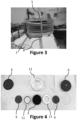
- the reactor 1 has an anode material 6, a filter 2 made of activated carbon fibers and a composition of the electrolytic solution making it possible to improve the desorption of pollutants and their elimination during electrolysis.
- the grid has openings/meshes greater than 0.20 cm 2 ; 0.25 cm 2 ; 0.30 cm 2 ; 0.35cm2 ; 0.40 cm 2 ; 0.45cm2 ; or 0.50 cm 2 .
- the chamber 3 comprises several pairs of anode 6 / filter 2, connected in series, the two faces of an electrode being able to be polarized during electrolysis.
- the surface of the holes is between 20 and 100 mm 2 , more precisely between 30 and 60 mm 2 .
- the anode layer is a porous material, which may be a TiOx foam or a TiOx membrane.
- the foam can have pores with a size between 60 and 300 ⁇ m.
- the membrane can have pores with a size between 0.1 and 5 ⁇ m.
- the means for driving the fluid are configured to allow pressure to be exerted on this downstream electrode so as to cause the gas bubbles formed during electrolysis to pass through this downstream electrode.
- the reactor comprises a regulation unit 14 connected to solenoid valves of the circulation 8 and recirculation 9 circuits, to the fluid drive means and to the electric current supply means, so as to be able to activate places the filtration or electrolysis operating mode, by action of the regulation unit 14 on the circulation circuits 8 and recirculation 9 as well as on the fluid drive means and on the electric current supply means.
- the regulation unit is able to reverse the direction of circulation of the flow in the reactor between the passage of the fluid in the reactor in filtration mode, and the passage of the electrolytic solution in electrolysis mode.
- the regulation unit is connected to a sensor for measuring the concentration of pollutants at output 5, the electrolysis mode being implemented when the concentration of pollutants rises above a given value, the mode filtration being put in place when the concentration of pollutants falls below a given value.
- the at least one layer of activated carbon is formed of grains of activated carbon.
- the inlet 4 has a conical shape (point upstream of the current), to distribute the water over the surface of the layer(s) of activated carbon fibers.
- an electric current passes through the at least one layer of activated carbon and into the layer of anodic material, respectively forming a cathode 7 and an anode 6.
- the reactors 1 are placed in series or in parallel, with respect to the flow of the fluid to be treated.
- the quality of the overall water at the outlet which is measured, in order to be able to measure the quantity of organic pollutants at the outlet.
- the quality of the water at the outlet drops, we reactivates a clean/regenerated filter (which was previously more used for adsorption), and a dirty filter is regenerated.
- the 1 column reactors can switch to regeneration mode, when the filters 2 allow at least 5% of organic pollutants to pass through.
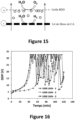
- the DDP remains overall at a very high level. As observed on the Figure 17 , increasing the filtration speed does not significantly resolve this problem. It should be noted that these results were not expected. Indeed, the size of these tight meshes still remains significantly greater than the size of the (micro)bubbles generated at the electrodes. However, the interactions of the bubbles with the surface of the material and the phenomena of bubble coalescence lead to this harmful effect for the process.
- the filtration speed (ie the flow) of the electrolytic solution is therefore a parameter key operating procedure, making it possible to avoid gas retention at the level of the bed of activated carbon fibers when it is located above a counter-electrode. This is explained by the increase in pressure at the filter, making it possible to encourage the passage of gas bubbles through the filter. Other parameters could affect this pressure at the filter, such as the thickness of the activated carbon bed, or the nature (in particular the porous structure) of the activated carbon bed. The porous structure of the activated carbon bed could also affect the pressure necessary to achieve to facilitate the passage of bubbles through.
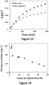
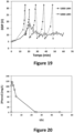
- the results of the Figure 20 And 21 show the evolution during regeneration of the concentration of phenol and total organic carbon, respectively.
- a filter of 10 layers of activated carbon fibers was used.
- a BDD grid type anode (large mesh size) is placed downstream of the filter, another upstream.
- the filtration surface is 19.6 cm 2 .
- a BDD anode and a stainless steel cathode are placed in the buffer volume for recirculation.
- the current intensity is 300 mA in the buffer volume, and 300 mA in the chamber.
- the filtration speed of the electrolytic solution is 5 m/h.
- the electrolyte solution contains 50 mM Na 2 SO 4 and its pH was adjusted to 13 with NaOH.
- the adsorption step was carried out with a phenol concentration of 10 mg/L and a flow rate of 2 L/h.
Landscapes
- Chemical & Material Sciences (AREA)
- Organic Chemistry (AREA)
- Chemical Kinetics & Catalysis (AREA)
- Engineering & Computer Science (AREA)
- Analytical Chemistry (AREA)
- Hydrology & Water Resources (AREA)
- Environmental & Geological Engineering (AREA)
- Water Supply & Treatment (AREA)
- Life Sciences & Earth Sciences (AREA)
- Electrochemistry (AREA)
- Materials Engineering (AREA)
- Metallurgy (AREA)
- Nanotechnology (AREA)
- Physics & Mathematics (AREA)
- Health & Medical Sciences (AREA)
- Electromagnetism (AREA)
- General Health & Medical Sciences (AREA)
- Toxicology (AREA)
- Inorganic Chemistry (AREA)
- General Chemical & Material Sciences (AREA)
- Water Treatment By Electricity Or Magnetism (AREA)
- Electrolytic Production Of Non-Metals, Compounds, Apparatuses Therefor (AREA)
Claims (16)
- Reaktor (1), der die kontinuierliche Frontalfiltration eines fließenden Fluids durch Adsorption von Schadstoffen auf einem Filter (2), dann eine Elektrolyse zur Regeneration des Filters (2) und zum Abbau und zur Mineralisierung der organischen Schadstoffe gestattet, wobei der Reaktor (1) aufweist:- eine Kammer (3) mit mindestens einem Einlass (4), der ein Fluid in die Kammer (3) liefert, und mindestens einem Auslass (5), der es gestattet, das Fluid aus der Kammer (3) abzuleiten;- Mittel zur Stromversorgung;- einen Zirkulationskreis (8) eines durch Adsorption von Schadstoffen auf dem Filter (2) zu behandelnden Fluids, der den Durchgang des zu behandelnden Fluids durch die Kammer (3) gestattet;- einen Rezirkulationskreis (9) einer Elektrolytlösung für die Elektrolyse, der den Auslass (5) mit dem Einlass (4) verbindet und durch ein offenes Puffervolumen (9a) führt, um die während der Elektrolyse erzeugten Gasblasen abzuleiten;- Fluidfördermittel;- wobei das gesamte während der Filtration zu behandelnde Fluid und der Elektrolytlösung und der während der Elektrolyse desorbierten organischen Schadstoffe nacheinander durch alle Elemente der Kammer (3) strömen, die mindestens aufweist:- einen porösen Filter (2), der mindestens eine Aktivkohleschicht aufweist, die die Adsorption der organischen Schadstoffe beim Fließen des zu behandelnden Fluids gestattet, wobei die Schicht(en) elektrisch mit den Mitteln zur Stromversorgung verbunden ist(sind), um die Schicht(en) nur bei der Elektrolyse zu polarisieren, wobei der Filter (2) die Kathode während der Elektrolyse und des Durchgangs der Elektrolytlösung und der desorbierten organischen Schadstoffe ist, die die Regeneration des Filters und die Entfernung der organischen Schadstoffe gestatten;- eine Anode (6) vor oder nach dem Filter (2), die mindestens eine Schicht Anodenmaterial und Öffnungen umfasst, die das Fließen des Fluid bei der Filtration und der Elektrolytlösung bei der Elektrolyse gestatten, wobei das Material elektrisch mit den Mitteln zur Stromversorgung verbunden ist, um es während der Elektrolyse als Anode für den Abbau und die Mineralisierung der desorbierten organischen Schadstoffe des Filters (2) zu polarisieren, wobei die Anode (6) und der Filters (2) horizontal in der vertikal angeordneten Kammer (3) des Reaktors platziert sind, wobei der Rezirkulationskreis (9) einen Aufwärtsstrom der Elektrolytlösung und der desorbierten organischen Schadstoffe innerhalb der Kammer (3) gewährleistet, die die Anode (6) und den Filter (2) umfasst, um das Ableiten der während der Elektrolyse gebildeten Gasblasen in das Puffervolumen (9a) des Rezirkulationskreises (9) zu begünstigen; wobei der Reaktor (1) eine Regeleinheit (14) umfasst, die mit Magnetventilen des Zirkulationskreises (8) und des Rezirkulationskreises (9), den Fluidfördermitteln und den Mitteln zur Stromversorgung verbunden ist, so dass durch das Einwirken der Regeleinheit (14) auf den Zirkulationskreis (8) und den Rezirkulationskreis (9) sowie auf die Fluidfördermittel und auf die Mittel zur Stromversorgung ein Filtrations- oder Elektrolyse-Betriebsmodus eingerichtet werden kann, um nach zwei Modi zu arbeiten:- im kontinuierlichen Filtrationsmodus des Fluids, das sich im Zirkulationskreis (8) zur Adsorption der organischen Schadstoffe auf dem Filter (2) verlagert, ohne Stromversorgung, ohne Rezirkulation des Fluids, oder- im Elektrolysemodus zur Regeneration des Filters (2) und zum Abbau und zur Mineralisierung der organischen Schadstoffe durch Anlegen eines elektrischen Stroms zwischen dem als Kathode verwendeten Filter (2) und der Anode (6), mit kontinuierlicher Rezirkulation der Elektrolytlösung und der desorbierten organischen Schadstoffe durch den Filter (2) und die Anode (6) der Kammer und dann in den Rezirkulationskreis (9).
- Reaktor (1) nach Anspruch 1, wobei die Anode (6) ein durchbrochenes Material oder ein Gitter aufweist, auf dem das Anodenmaterial abgelegt ist.
- Reaktor (1) nach Anspruch 1 oder 2, wobei, wenn eine Elektrode, die nach einer anderen im Verhältnis zur Strömungsrichtung des Fluids während der Regeneration platziert ist:- die Anode (6) ist, die Anode (6) ein durchbrochenes Material oder ein Gitter mit Öffnungen/Maschenweiten von mehr als 0,15 cm2 aufweist, die den Durchgang der während der Elektrolyse gebildeten Gasblasen gestatten; oder- der Filter (2) als Kathode verwendet wird, die Fluidfördermittel ausgelegt sind, um die Ausübung eines Drucks auf diese nachgelagerte Elektrode derart auszuüben, dass die während der Elektrolyse gebildeten Gasblasen diese nachgelagerte Elektrode passieren.
- Reaktor (1) nach einem der Ansprüche 1 bis 3, wobei der Reaktor ein Anodenmaterial aus bordotiertem Diamant oder aus substöchiometrischen Titanoxid aufweist, das den Abbau und die Mineralisierung der organischen Verbindungen gestattet.
- Reaktor (1) nach einem der Ansprüche 1 bis 4, wobei die mindestens eine Aktivkohleschicht aus Aktivkohlefasern gebildet ist.
- Reaktor (1) nach einem der Ansprüche 1 bis 4, wobei die mindestens eine Aktivkohleschicht aus Aktivkohlekörnern gebildet ist.
- Reaktor (1) nach einem der Ansprüche 1 bis 6, wobei die Kammer (3) mehrere Paare Anode (6)/Filter (2) umfasst, die in Reihe angebracht sind, wobei die beiden Seiten einer Elektrode bei der Elektrolyse polarisiert werden können.
- Reaktor (1) nach einem der Ansprüche 1 bis 7, wobei mindestens eine Anode, mindestens eine Kathode und Mittel zur Stromversorgung im offenen Puffervolumen (9a) enthalten sind, um den Abbau und die Mineralisierung der Schadstoffe während der Elektrolyse zu begünstigen, wie z. B. eine Anode, die mindestens eine bordotierte Diamantschicht oder aus substöchiometrischem Titanoxid umfasst.
- Reaktor (1) nach einem der Ansprüche 1 bis 8, wobei die Fluidfördermittel ausgelegt sind, um dem Rezirkulationskreis (9) zu gestatten, während der Elektrolyse eine Filtrationsgeschwindigkeit der Elektrolytlösung durch den Filter (2) von mehr als 2 m/h zu erreichen.
- Reaktor (1) nach einem der Ansprüche 1 bis 9, wobei die Regeleinheit in der Lage ist, die Zirkulationsrichtung des Fließens im Reaktor zwischen dem Durchgang des Fluids in den Reaktor im Filtrationsmodus und dem Durchgang der Elektrolytlösung im Elektrolysemodus umzukehren.
- Reaktor (1) nach einem der Ansprüche 1 bis 10, wobei die Regeleinheit mit einem Sensor zur Messung der Schadstoffkonzentration im Bereich des Auslasses (5) verbunden ist, wobei der Elektrolysemodus durchgeführt wird, wenn die Schadstoffkonzentration einen bestimmten Wert überschreitet, wobei der Filtrationsmodus durchgeführt wird, wenn die Schadstoffkonzentration unter einen bestimmten Wert fällt.
- Reaktor (1) nach einem der Ansprüche 1 bis 11, wobei das Fluid ein Gas oder eine Flüssigkeit wie eine wässrige Flüssigkeit ist.
- Reaktor (1) nach einem der Ansprüche 1 bis 12, wobei der Reaktor (1) in einem Körper (12) in Reihe geschaltet aufweist:- ein Wassereinlasselement,- eine erste nicht aktive Anodenschicht, die auf einem ersten Träger aufliegt,- ein erstes nichtleitendes Trennelement (11) mit mindestens einer eine Kathode (7) berührenden Dichtung, wobei die Kathode mehrere Schichten poröser Aktivkohlefasern aufweist, ein zweites nichtleitendes Trennelement (11) mit mindestens einer die Kathode (7) berührenden Dichtung,- eine zweite nicht aktive Anodenschicht, die auf einem zweiten Träger ruht,- ein Wasserauslasselement.
- System (10), das mehrere Reaktoren (1) nach einem der Ansprüche 1 bis 13 umfasst.
- System (10) nach Anspruch 14, wobei die Rezirkulationskreise (9) des Reaktorfluids (1) derart verbunden sind, dass sie ein gemeinsames offenes Puffervolumen (9a) aufweisen.
- System (10) nach einem der Ansprüche 14 oder 15, wobei die Reaktoren (1) in Reihe oder parallel im Verhältnis zur Fließrichtung des zu behandelnden Fluids angeordnet sind.
Applications Claiming Priority (1)
| Application Number | Priority Date | Filing Date | Title |
|---|---|---|---|
| FR2101151 | 2021-02-05 |
Publications (3)
| Publication Number | Publication Date |
|---|---|
| EP4039655A1 EP4039655A1 (de) | 2022-08-10 |
| EP4039655C0 EP4039655C0 (de) | 2024-07-03 |
| EP4039655B1 true EP4039655B1 (de) | 2024-07-03 |
Family
ID=75108576
Family Applications (1)
| Application Number | Title | Priority Date | Filing Date |
|---|---|---|---|
| EP22154591.6A Active EP4039655B1 (de) | 2021-02-05 | 2022-02-01 | Reaktor, der die kontinuierliche filtration einer durch einen filter fliessenden flüssigkeit ermöglicht und eine elektrochemische regeneration des filters in situ umfasst |
Country Status (3)
| Country | Link |
|---|---|
| US (1) | US20220250942A1 (de) |
| EP (1) | EP4039655B1 (de) |
| ES (1) | ES2991693T3 (de) |
Families Citing this family (4)
| Publication number | Priority date | Publication date | Assignee | Title |
|---|---|---|---|---|
| FR3078899B1 (fr) * | 2018-03-14 | 2021-03-05 | Univ Paris Est Marne La Vallee | Procede de regeneration du charbon actif par procede electro-fenton |
| EP4611927A1 (de) | 2022-10-31 | 2025-09-10 | Zaiput Flow Technologies LLC | Strömungsreaktoren sowie zugehörige systeme und verfahren |
| CN117945511B (zh) * | 2023-12-27 | 2026-02-13 | 湖南新锋科技有限公司 | 螺旋内循环式电化学废水处理设备及其运行方法 |
| CN119161064B (zh) * | 2024-11-12 | 2025-04-01 | 安徽永恒动力科技有限公司 | 一种蓄电池生产废水定量化监测处理装置及方法 |
Family Cites Families (22)
| Publication number | Priority date | Publication date | Assignee | Title |
|---|---|---|---|---|
| EP0141780A1 (de) * | 1983-10-11 | 1985-05-15 | Battelle Memorial Institute | Verfahren zur elektrochemischen Reinigung von Wasser |
| US6309532B1 (en) * | 1994-05-20 | 2001-10-30 | Regents Of The University Of California | Method and apparatus for capacitive deionization and electrochemical purification and regeneration of electrodes |
| US6346187B1 (en) * | 1999-01-21 | 2002-02-12 | The Regents Of The University Of California | Alternating-polarity operation for complete regeneration of electrochemical deionization system |
| RU2171139C1 (ru) * | 2000-01-05 | 2001-07-27 | Общество с ограниченной ответственностью "Аквафор" | Композиционный регенерируемый адсорбционный углеродный материал и способ его регенерации |
| WO2003027029A1 (en) * | 2001-09-19 | 2003-04-03 | Fluid Dynamics International Ltd. | Method and apparatus for the destruction of dyes and other organic molecules |
| NO321256B1 (no) * | 2002-08-26 | 2006-04-10 | Oro As | Elektrodekonstruksjoner, samt anvendelse derav |
| JP4384444B2 (ja) * | 2003-05-29 | 2009-12-16 | 株式会社荏原製作所 | 電気式脱塩装置及び電気透析装置 |
| CN105540763A (zh) * | 2005-10-06 | 2016-05-04 | 派克逖克斯公司 | 流体的电化学离子交换处理 |
| US20080073288A1 (en) * | 2006-04-21 | 2008-03-27 | Qinbai Fan | Multifunctional filtration and water purification systems |
| GB2438850B (en) * | 2006-04-28 | 2010-04-21 | Univ Manchester | Liquid treatment apparatus |
| KR100716206B1 (ko) * | 2006-12-27 | 2007-05-10 | 주식회사 루미웰엔지니어링 | 극성 물질 분리장치 |
| KR101082017B1 (ko) * | 2009-05-21 | 2011-11-10 | 최장수 | 스트레이너/필터 기능을 가지는 전해장치 및 이를 이용하는 유체유동 시스템 |
| DE102010034081A1 (de) * | 2010-08-12 | 2012-02-16 | Li-Tec Battery Gmbh | Umhüllung für eine elektrochemische Zelle |
| KR20120104719A (ko) * | 2011-03-14 | 2012-09-24 | 삼성전자주식회사 | 재생가능한 필터 유닛, 이를 포함하는 필터 장치 및 필터 장치의 구동방법 |
| KR20120107308A (ko) * | 2011-03-21 | 2012-10-02 | 삼성전자주식회사 | 재생가능한 금속 제거용 필터 유닛, 필터 장치 및 이의 구동방법 |
| EP2925677B1 (de) * | 2012-12-03 | 2018-03-21 | Axine Water Technologies Inc. | Effiziente behandlung von abwasser mithilfe einer elektrochemischen zelle |
| US20150329364A1 (en) * | 2014-05-13 | 2015-11-19 | Georgia-Pacific Chemicals Llc | Activated carbon products and methods for making and using same |
| WO2016166168A1 (en) * | 2015-04-14 | 2016-10-20 | Koninklijke Philips N.V. | Electrosorption purification system with recirculation |
| EP3402752B1 (de) * | 2016-01-15 | 2020-12-02 | Axine Water Technologies Inc. | Batteriezelle zur abwasserbehandlung mit erhöhter schadstoffentfernungsrate |
| CA3033532A1 (en) * | 2016-08-19 | 2018-02-22 | University Of Georgia Research Foundation, Inc. | Methods and systems for electrochemical oxidation of polyfluoroalkyl and perfluoroalkyl contaminants |
| EP3579968B1 (de) * | 2017-02-09 | 2023-04-05 | California Institute of Technology | Poröse kohlenstoffelektrode |
| FR3078899B1 (fr) | 2018-03-14 | 2021-03-05 | Univ Paris Est Marne La Vallee | Procede de regeneration du charbon actif par procede electro-fenton |
-
2022
- 2022-02-01 ES ES22154591T patent/ES2991693T3/es active Active
- 2022-02-01 EP EP22154591.6A patent/EP4039655B1/de active Active
- 2022-02-04 US US17/592,692 patent/US20220250942A1/en active Pending
Also Published As
| Publication number | Publication date |
|---|---|
| US20220250942A1 (en) | 2022-08-11 |
| ES2991693T3 (es) | 2024-12-04 |
| EP4039655C0 (de) | 2024-07-03 |
| EP4039655A1 (de) | 2022-08-10 |
Similar Documents
| Publication | Publication Date | Title |
|---|---|---|
| EP4039655B1 (de) | Reaktor, der die kontinuierliche filtration einer durch einen filter fliessenden flüssigkeit ermöglicht und eine elektrochemische regeneration des filters in situ umfasst | |
| EP3765186B1 (de) | Vorrichtung zur regeneration von aktivkohle | |
| JP6214064B2 (ja) | 電気化学セルを用いる廃水の効率的な処理 | |
| US6274028B1 (en) | Electrolytic wastewater treatment method and apparatus | |
| CN107162118B (zh) | 一种适用于水源水污染物去除的阴阳极内置式陶瓷微滤膜反应器 | |
| EP3850127B1 (de) | Bioelektrochemischer reaktor mit doppelter bioanode, verfahren zur anodischen regeneration und verwendung des reaktors für die mikrobielle elektrosynthese | |
| Kim et al. | Electrochemical degradation of organic dyes with a porous gold electrode | |
| EP0141780A1 (de) | Verfahren zur elektrochemischen Reinigung von Wasser | |
| JP2010064045A (ja) | ハイブリッド型水浄化装置およびそれを用いた水浄化方法 | |
| CN106986482A (zh) | 一种光电降解废水装置 | |
| FR2784979A1 (fr) | Procede electrochimique de desinfection des eaux par electroperoxydation et dispositif pour la mise en oeuvre d'un tel procede | |
| KR101352939B1 (ko) | 수처리 장치 및 그 방법 | |
| CN110730763A (zh) | 用于水溶性有机废物处理的设备和方法 | |
| JP5812874B2 (ja) | 微生物燃料電池システム | |
| EP0253749B1 (de) | Kontinuierliches Scheidungsverfahren durch Elektrophorese und Elektroosmose von elektrisch geladenen pulverisierten Feststoffen | |
| CN113003877A (zh) | 一种难降解有机废水的处理装置及方法 | |
| JP2007330914A (ja) | 酸化性雰囲気水製造方法および装置並びに水処理方法および装置 | |
| EP2718483A1 (de) | Verfahren zur behandlung eines filzelements durch perkolation mittels galvanisierung | |
| CN116615393B (zh) | 用于通过膜过滤和电化学氧化的废水处理的方法和系统 | |
| Chou et al. | Removal of color and COD from dyeing wastewater by paired electrochemical oxidation | |
| WO2021260020A1 (fr) | Dispositif d'electro-pales pour le traitement electrochimique d'effluents | |
| EP0183602A1 (de) | Verfahren und Vorrichtung zur Rückgewinnung von Silber aus Fixierbädern | |
| CN114180729B (zh) | 高效处理矿物尾渣浸出液废水的装置及方法 | |
| KR102766275B1 (ko) | 일정한 방향의 순흐름을 이용한 탈염 장치 및 탈염 방법 | |
| FR3085969A1 (fr) | Procede de regeneration in situ d'une bio-anode d'un dispositif de synthese bio-electrochimique |
Legal Events
| Date | Code | Title | Description |
|---|---|---|---|
| PUAI | Public reference made under article 153(3) epc to a published international application that has entered the european phase |
Free format text: ORIGINAL CODE: 0009012 |
|
| STAA | Information on the status of an ep patent application or granted ep patent |
Free format text: STATUS: THE APPLICATION HAS BEEN PUBLISHED |
|
| AK | Designated contracting states |
Kind code of ref document: A1 Designated state(s): AL AT BE BG CH CY CZ DE DK EE ES FI FR GB GR HR HU IE IS IT LI LT LU LV MC MK MT NL NO PL PT RO RS SE SI SK SM TR |
|
| STAA | Information on the status of an ep patent application or granted ep patent |
Free format text: STATUS: REQUEST FOR EXAMINATION WAS MADE |
|
| 17P | Request for examination filed |
Effective date: 20230209 |
|
| RBV | Designated contracting states (corrected) |
Designated state(s): AL AT BE BG CH CY CZ DE DK EE ES FI FR GB GR HR HU IE IS IT LI LT LU LV MC MK MT NL NO PL PT RO RS SE SI SK SM TR |
|
| GRAP | Despatch of communication of intention to grant a patent |
Free format text: ORIGINAL CODE: EPIDOSNIGR1 |
|
| STAA | Information on the status of an ep patent application or granted ep patent |
Free format text: STATUS: GRANT OF PATENT IS INTENDED |
|
| RIC1 | Information provided on ipc code assigned before grant |
Ipc: C02F 101/30 20060101ALN20240212BHEP Ipc: C02F 1/461 20060101ALN20240212BHEP Ipc: B01J 20/34 20060101ALI20240212BHEP Ipc: B01J 20/28 20060101ALI20240212BHEP Ipc: B01J 20/20 20060101ALI20240212BHEP Ipc: C02F 1/467 20060101ALI20240212BHEP Ipc: C02F 1/28 20060101AFI20240212BHEP |
|
| INTG | Intention to grant announced |
Effective date: 20240228 |
|
| GRAS | Grant fee paid |
Free format text: ORIGINAL CODE: EPIDOSNIGR3 |
|
| GRAA | (expected) grant |
Free format text: ORIGINAL CODE: 0009210 |
|
| STAA | Information on the status of an ep patent application or granted ep patent |
Free format text: STATUS: THE PATENT HAS BEEN GRANTED |
|
| AK | Designated contracting states |
Kind code of ref document: B1 Designated state(s): AL AT BE BG CH CY CZ DE DK EE ES FI FR GB GR HR HU IE IS IT LI LT LU LV MC MK MT NL NO PL PT RO RS SE SI SK SM TR |
|
| REG | Reference to a national code |
Ref country code: CH Ref legal event code: EP |
|
| REG | Reference to a national code |
Ref country code: DE Ref legal event code: R096 Ref document number: 602022004205 Country of ref document: DE |
|
| U01 | Request for unitary effect filed |
Effective date: 20240802 |
|
| U07 | Unitary effect registered |
Designated state(s): AT BE BG DE DK EE FI FR IT LT LU LV MT NL PT RO SE SI Effective date: 20240902 |
|
| REG | Reference to a national code |
Ref country code: ES Ref legal event code: FG2A Ref document number: 2991693 Country of ref document: ES Kind code of ref document: T3 Effective date: 20241204 |
|
| PG25 | Lapsed in a contracting state [announced via postgrant information from national office to epo] |
Ref country code: NO Free format text: LAPSE BECAUSE OF FAILURE TO SUBMIT A TRANSLATION OF THE DESCRIPTION OR TO PAY THE FEE WITHIN THE PRESCRIBED TIME-LIMIT Effective date: 20241003 |
|
| PG25 | Lapsed in a contracting state [announced via postgrant information from national office to epo] |
Ref country code: PL Free format text: LAPSE BECAUSE OF FAILURE TO SUBMIT A TRANSLATION OF THE DESCRIPTION OR TO PAY THE FEE WITHIN THE PRESCRIBED TIME-LIMIT Effective date: 20240703 Ref country code: GR Free format text: LAPSE BECAUSE OF FAILURE TO SUBMIT A TRANSLATION OF THE DESCRIPTION OR TO PAY THE FEE WITHIN THE PRESCRIBED TIME-LIMIT Effective date: 20241004 |
|
| PG25 | Lapsed in a contracting state [announced via postgrant information from national office to epo] |
Ref country code: IS Free format text: LAPSE BECAUSE OF FAILURE TO SUBMIT A TRANSLATION OF THE DESCRIPTION OR TO PAY THE FEE WITHIN THE PRESCRIBED TIME-LIMIT Effective date: 20241103 |
|
| PG25 | Lapsed in a contracting state [announced via postgrant information from national office to epo] |
Ref country code: HR Free format text: LAPSE BECAUSE OF FAILURE TO SUBMIT A TRANSLATION OF THE DESCRIPTION OR TO PAY THE FEE WITHIN THE PRESCRIBED TIME-LIMIT Effective date: 20240703 Ref country code: CZ Free format text: LAPSE BECAUSE OF FAILURE TO SUBMIT A TRANSLATION OF THE DESCRIPTION OR TO PAY THE FEE WITHIN THE PRESCRIBED TIME-LIMIT Effective date: 20240703 |
|
| PG25 | Lapsed in a contracting state [announced via postgrant information from national office to epo] |
Ref country code: RS Free format text: LAPSE BECAUSE OF FAILURE TO SUBMIT A TRANSLATION OF THE DESCRIPTION OR TO PAY THE FEE WITHIN THE PRESCRIBED TIME-LIMIT Effective date: 20241003 |
|
| PG25 | Lapsed in a contracting state [announced via postgrant information from national office to epo] |
Ref country code: RS Free format text: LAPSE BECAUSE OF FAILURE TO SUBMIT A TRANSLATION OF THE DESCRIPTION OR TO PAY THE FEE WITHIN THE PRESCRIBED TIME-LIMIT Effective date: 20241003 Ref country code: PL Free format text: LAPSE BECAUSE OF FAILURE TO SUBMIT A TRANSLATION OF THE DESCRIPTION OR TO PAY THE FEE WITHIN THE PRESCRIBED TIME-LIMIT Effective date: 20240703 Ref country code: NO Free format text: LAPSE BECAUSE OF FAILURE TO SUBMIT A TRANSLATION OF THE DESCRIPTION OR TO PAY THE FEE WITHIN THE PRESCRIBED TIME-LIMIT Effective date: 20241003 Ref country code: IS Free format text: LAPSE BECAUSE OF FAILURE TO SUBMIT A TRANSLATION OF THE DESCRIPTION OR TO PAY THE FEE WITHIN THE PRESCRIBED TIME-LIMIT Effective date: 20241103 Ref country code: HR Free format text: LAPSE BECAUSE OF FAILURE TO SUBMIT A TRANSLATION OF THE DESCRIPTION OR TO PAY THE FEE WITHIN THE PRESCRIBED TIME-LIMIT Effective date: 20240703 Ref country code: GR Free format text: LAPSE BECAUSE OF FAILURE TO SUBMIT A TRANSLATION OF THE DESCRIPTION OR TO PAY THE FEE WITHIN THE PRESCRIBED TIME-LIMIT Effective date: 20241004 Ref country code: CZ Free format text: LAPSE BECAUSE OF FAILURE TO SUBMIT A TRANSLATION OF THE DESCRIPTION OR TO PAY THE FEE WITHIN THE PRESCRIBED TIME-LIMIT Effective date: 20240703 |
|
| U20 | Renewal fee for the european patent with unitary effect paid |
Year of fee payment: 4 Effective date: 20250129 |
|
| PG25 | Lapsed in a contracting state [announced via postgrant information from national office to epo] |
Ref country code: SM Free format text: LAPSE BECAUSE OF FAILURE TO SUBMIT A TRANSLATION OF THE DESCRIPTION OR TO PAY THE FEE WITHIN THE PRESCRIBED TIME-LIMIT Effective date: 20240703 |
|
| PGFP | Annual fee paid to national office [announced via postgrant information from national office to epo] |
Ref country code: ES Payment date: 20250317 Year of fee payment: 4 |
|
| PG25 | Lapsed in a contracting state [announced via postgrant information from national office to epo] |
Ref country code: SK Free format text: LAPSE BECAUSE OF FAILURE TO SUBMIT A TRANSLATION OF THE DESCRIPTION OR TO PAY THE FEE WITHIN THE PRESCRIBED TIME-LIMIT Effective date: 20240703 |
|
| PLBE | No opposition filed within time limit |
Free format text: ORIGINAL CODE: 0009261 |
|
| STAA | Information on the status of an ep patent application or granted ep patent |
Free format text: STATUS: NO OPPOSITION FILED WITHIN TIME LIMIT |
|
| 26N | No opposition filed |
Effective date: 20250404 |
|
| PG25 | Lapsed in a contracting state [announced via postgrant information from national office to epo] |
Ref country code: MC Free format text: LAPSE BECAUSE OF FAILURE TO SUBMIT A TRANSLATION OF THE DESCRIPTION OR TO PAY THE FEE WITHIN THE PRESCRIBED TIME-LIMIT Effective date: 20240703 |
|
| REG | Reference to a national code |
Ref country code: CH Ref legal event code: PL |
|
| PG25 | Lapsed in a contracting state [announced via postgrant information from national office to epo] |
Ref country code: CH Free format text: LAPSE BECAUSE OF NON-PAYMENT OF DUE FEES Effective date: 20250228 |
|
| PG25 | Lapsed in a contracting state [announced via postgrant information from national office to epo] |
Ref country code: IE Free format text: LAPSE BECAUSE OF NON-PAYMENT OF DUE FEES Effective date: 20250201 |