EP4039655B1 - Reactor allowing the continuous filtering of a fluid flowing through a filter and with an on-site electrochemical regeneration of the filter - Google Patents
Reactor allowing the continuous filtering of a fluid flowing through a filter and with an on-site electrochemical regeneration of the filter Download PDFInfo
- Publication number
- EP4039655B1 EP4039655B1 EP22154591.6A EP22154591A EP4039655B1 EP 4039655 B1 EP4039655 B1 EP 4039655B1 EP 22154591 A EP22154591 A EP 22154591A EP 4039655 B1 EP4039655 B1 EP 4039655B1
- Authority
- EP
- European Patent Office
- Prior art keywords
- anode
- filter
- reactor
- fluid
- electrolysis
- Prior art date
- Legal status (The legal status is an assumption and is not a legal conclusion. Google has not performed a legal analysis and makes no representation as to the accuracy of the status listed.)
- Active
Links
Images


Classifications
-
- C—CHEMISTRY; METALLURGY
- C02—TREATMENT OF WATER, WASTE WATER, SEWAGE, OR SLUDGE
- C02F—TREATMENT OF WATER, WASTE WATER, SEWAGE, OR SLUDGE
- C02F1/00—Treatment of water, waste water, or sewage
- C02F1/28—Treatment of water, waste water, or sewage by sorption
- C02F1/283—Treatment of water, waste water, or sewage by sorption using coal, charred products, or inorganic mixtures containing them
-
- B—PERFORMING OPERATIONS; TRANSPORTING
- B01—PHYSICAL OR CHEMICAL PROCESSES OR APPARATUS IN GENERAL
- B01J—CHEMICAL OR PHYSICAL PROCESSES, e.g. CATALYSIS OR COLLOID CHEMISTRY; THEIR RELEVANT APPARATUS
- B01J20/00—Solid sorbent compositions or filter aid compositions; Sorbents for chromatography; Processes for preparing, regenerating or reactivating thereof
- B01J20/02—Solid sorbent compositions or filter aid compositions; Sorbents for chromatography; Processes for preparing, regenerating or reactivating thereof comprising inorganic material
- B01J20/20—Solid sorbent compositions or filter aid compositions; Sorbents for chromatography; Processes for preparing, regenerating or reactivating thereof comprising inorganic material comprising free carbon; comprising carbon obtained by carbonising processes
-
- B—PERFORMING OPERATIONS; TRANSPORTING
- B01—PHYSICAL OR CHEMICAL PROCESSES OR APPARATUS IN GENERAL
- B01J—CHEMICAL OR PHYSICAL PROCESSES, e.g. CATALYSIS OR COLLOID CHEMISTRY; THEIR RELEVANT APPARATUS
- B01J20/00—Solid sorbent compositions or filter aid compositions; Sorbents for chromatography; Processes for preparing, regenerating or reactivating thereof
- B01J20/28—Solid sorbent compositions or filter aid compositions; Sorbents for chromatography; Processes for preparing, regenerating or reactivating thereof characterised by their form or physical properties
- B01J20/28014—Solid sorbent compositions or filter aid compositions; Sorbents for chromatography; Processes for preparing, regenerating or reactivating thereof characterised by their form or physical properties characterised by their form
- B01J20/28033—Membrane, sheet, cloth, pad, lamellar or mat
-
- B—PERFORMING OPERATIONS; TRANSPORTING
- B01—PHYSICAL OR CHEMICAL PROCESSES OR APPARATUS IN GENERAL
- B01J—CHEMICAL OR PHYSICAL PROCESSES, e.g. CATALYSIS OR COLLOID CHEMISTRY; THEIR RELEVANT APPARATUS
- B01J20/00—Solid sorbent compositions or filter aid compositions; Sorbents for chromatography; Processes for preparing, regenerating or reactivating thereof
- B01J20/28—Solid sorbent compositions or filter aid compositions; Sorbents for chromatography; Processes for preparing, regenerating or reactivating thereof characterised by their form or physical properties
- B01J20/28054—Solid sorbent compositions or filter aid compositions; Sorbents for chromatography; Processes for preparing, regenerating or reactivating thereof characterised by their form or physical properties characterised by their surface properties or porosity
- B01J20/28057—Surface area, e.g. B.E.T specific surface area
-
- B—PERFORMING OPERATIONS; TRANSPORTING
- B01—PHYSICAL OR CHEMICAL PROCESSES OR APPARATUS IN GENERAL
- B01J—CHEMICAL OR PHYSICAL PROCESSES, e.g. CATALYSIS OR COLLOID CHEMISTRY; THEIR RELEVANT APPARATUS
- B01J20/00—Solid sorbent compositions or filter aid compositions; Sorbents for chromatography; Processes for preparing, regenerating or reactivating thereof
- B01J20/28—Solid sorbent compositions or filter aid compositions; Sorbents for chromatography; Processes for preparing, regenerating or reactivating thereof characterised by their form or physical properties
- B01J20/28054—Solid sorbent compositions or filter aid compositions; Sorbents for chromatography; Processes for preparing, regenerating or reactivating thereof characterised by their form or physical properties characterised by their surface properties or porosity
- B01J20/28078—Pore diameter
- B01J20/2808—Pore diameter being less than 2 nm, i.e. micropores or nanopores
-
- B—PERFORMING OPERATIONS; TRANSPORTING
- B01—PHYSICAL OR CHEMICAL PROCESSES OR APPARATUS IN GENERAL
- B01J—CHEMICAL OR PHYSICAL PROCESSES, e.g. CATALYSIS OR COLLOID CHEMISTRY; THEIR RELEVANT APPARATUS
- B01J20/00—Solid sorbent compositions or filter aid compositions; Sorbents for chromatography; Processes for preparing, regenerating or reactivating thereof
- B01J20/28—Solid sorbent compositions or filter aid compositions; Sorbents for chromatography; Processes for preparing, regenerating or reactivating thereof characterised by their form or physical properties
- B01J20/28054—Solid sorbent compositions or filter aid compositions; Sorbents for chromatography; Processes for preparing, regenerating or reactivating thereof characterised by their form or physical properties characterised by their surface properties or porosity
- B01J20/28088—Pore-size distribution
-
- B—PERFORMING OPERATIONS; TRANSPORTING
- B01—PHYSICAL OR CHEMICAL PROCESSES OR APPARATUS IN GENERAL
- B01J—CHEMICAL OR PHYSICAL PROCESSES, e.g. CATALYSIS OR COLLOID CHEMISTRY; THEIR RELEVANT APPARATUS
- B01J20/00—Solid sorbent compositions or filter aid compositions; Sorbents for chromatography; Processes for preparing, regenerating or reactivating thereof
- B01J20/30—Processes for preparing, regenerating, or reactivating
- B01J20/34—Regenerating or reactivating
- B01J20/3416—Regenerating or reactivating of sorbents or filter aids comprising free carbon, e.g. activated carbon
-
- B—PERFORMING OPERATIONS; TRANSPORTING
- B01—PHYSICAL OR CHEMICAL PROCESSES OR APPARATUS IN GENERAL
- B01J—CHEMICAL OR PHYSICAL PROCESSES, e.g. CATALYSIS OR COLLOID CHEMISTRY; THEIR RELEVANT APPARATUS
- B01J20/00—Solid sorbent compositions or filter aid compositions; Sorbents for chromatography; Processes for preparing, regenerating or reactivating thereof
- B01J20/30—Processes for preparing, regenerating, or reactivating
- B01J20/34—Regenerating or reactivating
- B01J20/3441—Regeneration or reactivation by electric current, ultrasound or irradiation, e.g. electromagnetic radiation such as X-rays, UV, light, microwaves
-
- C—CHEMISTRY; METALLURGY
- C02—TREATMENT OF WATER, WASTE WATER, SEWAGE, OR SLUDGE
- C02F—TREATMENT OF WATER, WASTE WATER, SEWAGE, OR SLUDGE
- C02F1/00—Treatment of water, waste water, or sewage
- C02F1/008—Control or steering systems not provided for elsewhere in subclass C02F
-
- C—CHEMISTRY; METALLURGY
- C02—TREATMENT OF WATER, WASTE WATER, SEWAGE, OR SLUDGE
- C02F—TREATMENT OF WATER, WASTE WATER, SEWAGE, OR SLUDGE
- C02F1/00—Treatment of water, waste water, or sewage
- C02F1/46—Treatment of water, waste water, or sewage by electrochemical methods
- C02F1/461—Treatment of water, waste water, or sewage by electrochemical methods by electrolysis
- C02F1/467—Treatment of water, waste water, or sewage by electrochemical methods by electrolysis by electrochemical disinfection; by electrooxydation or by electroreduction
- C02F1/4672—Treatment of water, waste water, or sewage by electrochemical methods by electrolysis by electrochemical disinfection; by electrooxydation or by electroreduction by electrooxydation
-
- C—CHEMISTRY; METALLURGY
- C25—ELECTROLYTIC OR ELECTROPHORETIC PROCESSES; APPARATUS THEREFOR
- C25B—ELECTROLYTIC OR ELECTROPHORETIC PROCESSES FOR THE PRODUCTION OF COMPOUNDS OR NON-METALS; APPARATUS THEREFOR
- C25B15/00—Operating or servicing cells
- C25B15/08—Supplying or removing reactants or electrolytes; Regeneration of electrolytes
- C25B15/081—Supplying products to non-electrochemical reactors that are combined with the electrochemical cell, e.g. Sabatier reactor
-
- C—CHEMISTRY; METALLURGY
- C02—TREATMENT OF WATER, WASTE WATER, SEWAGE, OR SLUDGE
- C02F—TREATMENT OF WATER, WASTE WATER, SEWAGE, OR SLUDGE
- C02F1/00—Treatment of water, waste water, or sewage
- C02F1/46—Treatment of water, waste water, or sewage by electrochemical methods
- C02F1/461—Treatment of water, waste water, or sewage by electrochemical methods by electrolysis
- C02F1/46104—Devices therefor; Their operating or servicing
- C02F1/46109—Electrodes
- C02F2001/46133—Electrodes characterised by the material
- C02F2001/46138—Electrodes comprising a substrate and a coating
- C02F2001/46147—Diamond coating
-
- C—CHEMISTRY; METALLURGY
- C02—TREATMENT OF WATER, WASTE WATER, SEWAGE, OR SLUDGE
- C02F—TREATMENT OF WATER, WASTE WATER, SEWAGE, OR SLUDGE
- C02F1/00—Treatment of water, waste water, or sewage
- C02F1/46—Treatment of water, waste water, or sewage by electrochemical methods
- C02F1/461—Treatment of water, waste water, or sewage by electrochemical methods by electrolysis
- C02F1/46104—Devices therefor; Their operating or servicing
- C02F1/46109—Electrodes
- C02F2001/46152—Electrodes characterised by the shape or form
- C02F2001/46157—Perforated or foraminous electrodes
-
- C—CHEMISTRY; METALLURGY
- C02—TREATMENT OF WATER, WASTE WATER, SEWAGE, OR SLUDGE
- C02F—TREATMENT OF WATER, WASTE WATER, SEWAGE, OR SLUDGE
- C02F2101/00—Nature of the contaminant
- C02F2101/30—Organic compounds
-
- C—CHEMISTRY; METALLURGY
- C02—TREATMENT OF WATER, WASTE WATER, SEWAGE, OR SLUDGE
- C02F—TREATMENT OF WATER, WASTE WATER, SEWAGE, OR SLUDGE
- C02F2201/00—Apparatus for treatment of water, waste water or sewage
- C02F2201/002—Construction details of the apparatus
- C02F2201/003—Coaxial constructions, e.g. a cartridge located coaxially within another
-
- C—CHEMISTRY; METALLURGY
- C02—TREATMENT OF WATER, WASTE WATER, SEWAGE, OR SLUDGE
- C02F—TREATMENT OF WATER, WASTE WATER, SEWAGE, OR SLUDGE
- C02F2201/00—Apparatus for treatment of water, waste water or sewage
- C02F2201/46—Apparatus for electrochemical processes
- C02F2201/461—Electrolysis apparatus
- C02F2201/46105—Details relating to the electrolytic devices
- C02F2201/4612—Controlling or monitoring
- C02F2201/46145—Fluid flow
-
- C—CHEMISTRY; METALLURGY
- C02—TREATMENT OF WATER, WASTE WATER, SEWAGE, OR SLUDGE
- C02F—TREATMENT OF WATER, WASTE WATER, SEWAGE, OR SLUDGE
- C02F2201/00—Apparatus for treatment of water, waste water or sewage
- C02F2201/46—Apparatus for electrochemical processes
- C02F2201/461—Electrolysis apparatus
- C02F2201/46105—Details relating to the electrolytic devices
- C02F2201/4618—Supplying or removing reactants or electrolyte
- C02F2201/46185—Recycling the cathodic or anodic feed
-
- C—CHEMISTRY; METALLURGY
- C02—TREATMENT OF WATER, WASTE WATER, SEWAGE, OR SLUDGE
- C02F—TREATMENT OF WATER, WASTE WATER, SEWAGE, OR SLUDGE
- C02F2209/00—Controlling or monitoring parameters in water treatment
- C02F2209/003—Downstream control, i.e. outlet monitoring, e.g. to check the treating agents, such as halogens or ozone, leaving the process
-
- C—CHEMISTRY; METALLURGY
- C02—TREATMENT OF WATER, WASTE WATER, SEWAGE, OR SLUDGE
- C02F—TREATMENT OF WATER, WASTE WATER, SEWAGE, OR SLUDGE
- C02F2209/00—Controlling or monitoring parameters in water treatment
- C02F2209/20—Total organic carbon [TOC]
-
- C—CHEMISTRY; METALLURGY
- C02—TREATMENT OF WATER, WASTE WATER, SEWAGE, OR SLUDGE
- C02F—TREATMENT OF WATER, WASTE WATER, SEWAGE, OR SLUDGE
- C02F2303/00—Specific treatment goals
- C02F2303/16—Regeneration of sorbents, filters
-
- C—CHEMISTRY; METALLURGY
- C02—TREATMENT OF WATER, WASTE WATER, SEWAGE, OR SLUDGE
- C02F—TREATMENT OF WATER, WASTE WATER, SEWAGE, OR SLUDGE
- C02F2305/00—Use of specific compounds during water treatment
- C02F2305/02—Specific form of oxidant
- C02F2305/023—Reactive oxygen species, singlet oxygen, OH radical
-
- C—CHEMISTRY; METALLURGY
- C02—TREATMENT OF WATER, WASTE WATER, SEWAGE, OR SLUDGE
- C02F—TREATMENT OF WATER, WASTE WATER, SEWAGE, OR SLUDGE
- C02F2305/00—Use of specific compounds during water treatment
- C02F2305/02—Specific form of oxidant
- C02F2305/026—Fenton's reagent
Definitions
- activated carbon only allows pollutants to be separated by adsorption of pollutants on its surface, but it does not allow them to be degraded.
- Activated carbon is loaded/saturated with organic pollutants and becomes waste, which must be treated.
- treatment should lead to both the regeneration/reuse of granular activated carbon (in order to improve the sustainability and profitability of the process), and the degradation of organic pollutants (in order to avoid any contamination of the environment).
- Thermal regeneration is the most widely used process. The effectiveness depends closely on the nature of the compounds adsorbed and the nature of the interactions with the surface of the activated carbon. Thermal regeneration with an inert atmosphere often leads to low recovery of adsorption capacity, due to insufficient removal of chemisorbed compounds. Additionally, additional treatment is normally required for the degradation of desorbed pollutants. Higher removal rates are achieved during heat treatment under oxidizing conditions, but the microporous structure of the activated carbon is then greatly affected. In addition, thermal processes are expensive. They require the installation of centralized regeneration units, thus involving transport of activated carbon from the depollution units to the material regeneration units.
- Chemical regeneration by oxidation using for example ozone or the Fenton reaction, can also strongly affect the chemical and textural characteristics of activated carbon. Additionally, low regeneration efficiency is often observed for microporous activated carbons, and chemical regeneration is thus often applied only to mesoporous or non-porous materials.
- porous fibers have unique characteristics compared to granular or powdered activated carbon.
- the fine fiber shape and associated open porosity reduces the resistance to intraparticle diffusion and gives this material mechanical and geometric characteristics suitable for the design of electrochemical reactors.
- the at least one layer of activated carbon is formed of activated carbon fibers.
- the at least one layer of activated carbon is formed of grains of activated carbon.
- the chamber comprises several anode/filter pairs, connected in series, the two faces of an electrode being able to be polarized during electrolysis.
- At least one anode, at least one cathode and means for supplying electric current are included in the open buffer volume, in order to promote the elimination of pollutants during the electrolysis, such as an anode comprising at least minus a layer of boron-doped diamond or sub-stoichiometric titanium oxide.
- the pH of the electrolytic solution is adjusted to a pH greater than 9, in order to promote the desorption of pollutants during electrolysis.
- the reactor comprises a regulation unit connected to solenoid valves of the circulation and recirculation circuits, to the fluid driving means and to the electric current supply means, so as to be able to set up the mode filtration or electrolysis operation, by action of the regulation unit on the circulation and recirculation circuits as well as on the fluid drive means and on the electric current supply means.
- the fluid driving means are configured to allow the recirculation circuit to achieve a filtration speed of the fluid through the filter greater than 2 m/h.
- the regulation unit is able to reverse the direction of circulation of the flow in the reactor between the passage of the fluid in the reactor in filtration mode, and the passage of the electrolytic solution in electrolysis mode.
- the regulation unit is connected to a sensor for measuring the concentration of pollutants at the outlet, the electrolysis mode being implemented when the concentration of pollutants rises above a given value, the filtration mode being implemented when the concentration of pollutants falls below a given value.
- the fluid is a gas or a liquid such as an aqueous liquid.
- the reactor 1 has an anode material 6, a filter 2 made of activated carbon fibers and a composition of the electrolytic solution making it possible to improve the desorption of pollutants and their elimination during electrolysis.
- the grid has openings/meshes greater than 0.20 cm 2 ; 0.25 cm 2 ; 0.30 cm 2 ; 0.35cm2 ; 0.40 cm 2 ; 0.45cm2 ; or 0.50 cm 2 .
- the chamber 3 comprises several pairs of anode 6 / filter 2, connected in series, the two faces of an electrode being able to be polarized during electrolysis.
- the surface of the holes is between 20 and 100 mm 2 , more precisely between 30 and 60 mm 2 .
- the anode layer is a porous material, which may be a TiOx foam or a TiOx membrane.
- the foam can have pores with a size between 60 and 300 ⁇ m.
- the membrane can have pores with a size between 0.1 and 5 ⁇ m.
- the means for driving the fluid are configured to allow pressure to be exerted on this downstream electrode so as to cause the gas bubbles formed during electrolysis to pass through this downstream electrode.
- the reactor comprises a regulation unit 14 connected to solenoid valves of the circulation 8 and recirculation 9 circuits, to the fluid drive means and to the electric current supply means, so as to be able to activate places the filtration or electrolysis operating mode, by action of the regulation unit 14 on the circulation circuits 8 and recirculation 9 as well as on the fluid drive means and on the electric current supply means.
- the regulation unit is able to reverse the direction of circulation of the flow in the reactor between the passage of the fluid in the reactor in filtration mode, and the passage of the electrolytic solution in electrolysis mode.
- the regulation unit is connected to a sensor for measuring the concentration of pollutants at output 5, the electrolysis mode being implemented when the concentration of pollutants rises above a given value, the mode filtration being put in place when the concentration of pollutants falls below a given value.
- the at least one layer of activated carbon is formed of grains of activated carbon.
- the inlet 4 has a conical shape (point upstream of the current), to distribute the water over the surface of the layer(s) of activated carbon fibers.
- an electric current passes through the at least one layer of activated carbon and into the layer of anodic material, respectively forming a cathode 7 and an anode 6.
- the reactors 1 are placed in series or in parallel, with respect to the flow of the fluid to be treated.
- the quality of the overall water at the outlet which is measured, in order to be able to measure the quantity of organic pollutants at the outlet.
- the quality of the water at the outlet drops, we reactivates a clean/regenerated filter (which was previously more used for adsorption), and a dirty filter is regenerated.
- the 1 column reactors can switch to regeneration mode, when the filters 2 allow at least 5% of organic pollutants to pass through.
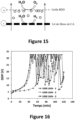
- the DDP remains overall at a very high level. As observed on the Figure 17 , increasing the filtration speed does not significantly resolve this problem. It should be noted that these results were not expected. Indeed, the size of these tight meshes still remains significantly greater than the size of the (micro)bubbles generated at the electrodes. However, the interactions of the bubbles with the surface of the material and the phenomena of bubble coalescence lead to this harmful effect for the process.
- the filtration speed (ie the flow) of the electrolytic solution is therefore a parameter key operating procedure, making it possible to avoid gas retention at the level of the bed of activated carbon fibers when it is located above a counter-electrode. This is explained by the increase in pressure at the filter, making it possible to encourage the passage of gas bubbles through the filter. Other parameters could affect this pressure at the filter, such as the thickness of the activated carbon bed, or the nature (in particular the porous structure) of the activated carbon bed. The porous structure of the activated carbon bed could also affect the pressure necessary to achieve to facilitate the passage of bubbles through.
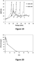
- the results of the Figure 20 And 21 show the evolution during regeneration of the concentration of phenol and total organic carbon, respectively.
- a filter of 10 layers of activated carbon fibers was used.
- a BDD grid type anode (large mesh size) is placed downstream of the filter, another upstream.
- the filtration surface is 19.6 cm 2 .
- a BDD anode and a stainless steel cathode are placed in the buffer volume for recirculation.
- the current intensity is 300 mA in the buffer volume, and 300 mA in the chamber.
- the filtration speed of the electrolytic solution is 5 m/h.
- the electrolyte solution contains 50 mM Na 2 SO 4 and its pH was adjusted to 13 with NaOH.
- the adsorption step was carried out with a phenol concentration of 10 mg/L and a flow rate of 2 L/h.
Landscapes
- Chemical & Material Sciences (AREA)
- Organic Chemistry (AREA)
- Chemical Kinetics & Catalysis (AREA)
- Engineering & Computer Science (AREA)
- Analytical Chemistry (AREA)
- Hydrology & Water Resources (AREA)
- Environmental & Geological Engineering (AREA)
- Water Supply & Treatment (AREA)
- Life Sciences & Earth Sciences (AREA)
- Electrochemistry (AREA)
- Materials Engineering (AREA)
- Metallurgy (AREA)
- Nanotechnology (AREA)
- Physics & Mathematics (AREA)
- Health & Medical Sciences (AREA)
- Electromagnetism (AREA)
- General Health & Medical Sciences (AREA)
- Toxicology (AREA)
- Inorganic Chemistry (AREA)
- General Chemical & Material Sciences (AREA)
- Water Treatment By Electricity Or Magnetism (AREA)
- Electrolytic Production Of Non-Metals, Compounds, Apparatuses Therefor (AREA)
Description
La présente invention concerne un réacteur permettant la filtration frontale en continu d'un fluide en écoulement pour l'adsorption de polluants sur un filtre, et une électrolyse pour la régénération électrochimique in situ du filtre et l'élimination des polluants organiques.The present invention relates to a reactor allowing continuous frontal filtration of a flowing fluid for the adsorption of pollutants on a filter, and electrolysis for the in situ electrochemical regeneration of the filter and the elimination of organic pollutants.
Le développement de systèmes de traitement de l'eau durables atteignant des taux élevés d'élimination des micropolluants est un défi important pour l'ingénierie environnementale. Le charbon actif (CA) est actuellement largement utilisé dans les usines de traitement de l'eau, car il s'est avéré être un adsorbant efficace pour l'élimination des composés organiques de l'eau. Ceci est dû à sa grande surface spécifique, à sa microporosité interne ainsi qu'à la présence de grandes quantités de divers groupes fonctionnels de surface. Ce matériau est aussi très utilisé en traitement de l'air.The development of sustainable water treatment systems achieving high rates of micropollutant removal is an important challenge for environmental engineering. Activated carbon (AC) is currently widely used in water treatment plants, as it has been shown to be an effective adsorbent for the removal of organic compounds from water. This is due to its large specific surface area, internal microporosity as well as the presence of large amounts of various surface functional groups. This material is also widely used in air treatment.
Cependant, le charbon actif permet seulement de séparer les polluants par adsorption des polluants à sa surface, mais il ne permet pas de les dégrader.However, activated carbon only allows pollutants to be separated by adsorption of pollutants on its surface, but it does not allow them to be degraded.
Le charbon actif est chargé/saturé en polluants organiques et devient un déchet, qui doit être traité. Dans l'idéal, le traitement doit conduire à la fois à la régénération/réutilisation du charbon actif en grains (afin d'améliorer la durabilité et la rentabilité du procédé), et à la dégradation des polluants organiques (afin d'éviter toute contamination de l'environnement).Activated carbon is loaded/saturated with organic pollutants and becomes waste, which must be treated. Ideally, treatment should lead to both the regeneration/reuse of granular activated carbon (in order to improve the sustainability and profitability of the process), and the degradation of organic pollutants (in order to avoid any contamination of the environment).
Alors que l'efficacité et les mécanismes d'adsorption d'une large gamme de composés organiques sur divers matériaux de charbon actif (grains, poudres, fibres) ont déjà été largement rapportés dans la littérature, il est toujours nécessaire de développer des procédés innovants et efficaces pour la régénération du charbon actif usé/saturé/chargé en polluants.While the efficiency and mechanisms of adsorption of a wide range of organic compounds onto various activated carbon materials (grains, powders, fibers) have already been widely reported in the literature, there is still a need to develop innovative processes and effective for the regeneration of spent/saturated/pollutant-laden activated carbon.
La régénération thermique est le procédé le plus largement utilisé. L'efficacité dépend étroitement de la nature des composés adsorbés et de la nature des interactions avec la surface du charbon actif. La régénération thermique avec une atmosphère inerte conduit souvent à une faible récupération de la capacité d'adsorption, en raison de l'élimination insuffisante des composés chimisorbés. De plus, un traitement supplémentaire est normalement nécessaire pour la dégradation des polluants désorbés. Des taux d'élimination plus élevés sont atteints pendant le traitement thermique dans des conditions oxydantes, mais la structure microporeuse du charbon actif est alors fortement affectée. De plus, les procédés thermiques sont coûteux. Ils nécessitent la mise en place d'unités centralisées de régénération, impliquant ainsi un transport du charbon actif depuis les unités de dépollution vers les unités de régénération du matériau.Thermal regeneration is the most widely used process. The effectiveness depends closely on the nature of the compounds adsorbed and the nature of the interactions with the surface of the activated carbon. Thermal regeneration with an inert atmosphere often leads to low recovery of adsorption capacity, due to insufficient removal of chemisorbed compounds. Additionally, additional treatment is normally required for the degradation of desorbed pollutants. Higher removal rates are achieved during heat treatment under oxidizing conditions, but the microporous structure of the activated carbon is then greatly affected. In addition, thermal processes are expensive. They require the installation of centralized regeneration units, thus involving transport of activated carbon from the depollution units to the material regeneration units.
Par ailleurs, les procédés d'électro-oxydation (oxydation anodique, électro-Fenton) permettent de leur côté de dégrader complètement les polluants organiques, jusqu'à la minéralisation complète. Mais leur inconvénient réside dans leur faible efficacité énergétique lorsqu'ils sont utilisés pour le traitement des effluents faiblement concentrés, tels que c'est le cas au niveau des stations de traitement des eaux usées et des usines d'eau potable.Furthermore, electro-oxidation processes (anodic oxidation, electro-Fenton) allow them to completely degrade the organic pollutants, until complete mineralization. But their disadvantage lies in their low energy efficiency when they are used for the treatment of weakly concentrated effluents, such as is the case at wastewater treatment plants and drinking water plants.
La régénération chimique par oxydation, en utilisant par exemple l'ozone ou la réaction de Fenton, peut également affecter fortement les caractéristiques chimiques et texturales du charbon actif. De plus, une faible efficacité de régénération est souvent observée pour les charbons actifs microporeux, et la régénération chimique est ainsi souvent appliquée uniquement aux matériaux mésoporeux ou non poreux.Chemical regeneration by oxidation, using for example ozone or the Fenton reaction, can also strongly affect the chemical and textural characteristics of activated carbon. Additionally, low regeneration efficiency is often observed for microporous activated carbons, and chemical regeneration is thus often applied only to mesoporous or non-porous materials.
Parmi les formes diverses du charbon actif, les fibres poreuses présentent des caractéristiques uniques par rapport au charbon actif granulaire ou en poudre. La forme en fibres fines et la porosité ouverte associée réduit la résistance à la diffusion intra-particulaire et confère à ce matériau des caractéristiques mécaniques et géométriques adaptées à la conception des réacteurs électrochimiques.Among the various forms of activated carbon, porous fibers have unique characteristics compared to granular or powdered activated carbon. The fine fiber shape and associated open porosity reduces the resistance to intraparticle diffusion and gives this material mechanical and geometric characteristics suitable for the design of electrochemical reactors.
Le charbon actif est un matériau efficace pour l'adsorption de composés organiques et il peut être polarisé en tant que cathode, notamment pour la génération électrochimique de H2O2 pendant le traitement de l'eau. Par rapport aux lits de grains de charbon actif, les fibres poreuses de charbon actif permettent d'assurer un meilleur niveau d'interconnexion au niveau de la microstructure, et ainsi de réduire les chutes ohmiques ainsi que les zones mortes (zones non-électro-actives) lors de leur utilisation en tant qu'électrode. Leur porosité ouverte permet aussi d'améliorer les cinétiques d'adsorption. Il est ainsi possible de mettre en place des lits de charbon actif présentant une épaisseur plus faible et/ou d'utiliser une vitesse de filtration plus élevée.Activated carbon is an effective material for the adsorption of organic compounds and it can be polarized as a cathode, especially for the electrochemical generation of H 2 O 2 during water treatment. Compared to beds of activated carbon grains, porous activated carbon fibers ensure a better level of interconnection at the microstructure level, and thus reduce ohmic drops as well as dead zones (non-electro-electrical zones). active) when used as an electrode. Their open porosity also makes it possible to improve adsorption kinetics. It is thus possible to put in place activated carbon beds having a lower thickness and/or to use a higher filtration speed.
Le procédé de régénération est un procédé d'électrolyse, plus précisément d'électro-oxydation, pour lequel des applications en réacteur discontinu (batch) sont majoritairement connues. La possibilité de faire passer la solution à traiter au travers des matériaux anodique et cathodique en mode filtration frontale, au cours du procédé d'électro-oxydation, n'est pas décrite dans la littérature. En ce qui concerne les études de régénération électrochimique, peu d'études portent sur l'utilisation de fibres de charbon actif. Plusieurs études n'utilisent pas non plus le charbon actif comme électrode. Le charbon actif est alors souvent seulement placé dans la solution électrolytique. De plus, beaucoup d'études sur la régénération électrochimique ne mettent en place que des configurations n'impliquant pas de dégradation et de minéralisation des composés organiques qui étaient adsorbés par le filtre (seulement le phénomène de désorption est mis en place). Comme déjà indiqué précédemment, les études ne décrivent pas non plus des systèmes permettant à la solution électrolytique de passer successivement au travers du filtre (utilisé en tant que cathode) et de la contre-électrode (l'anode), lors de la régénération électrochimique. Les publications plus spécifiques relatives à la régénération par électro-oxydation de fibres de charbon actif ne rapportent que des résultats en réacteur discontinu (« batch »).The regeneration process is an electrolysis process, more precisely electro-oxidation, for which applications in batch reactors are mainly known. The possibility of passing the solution to be treated through the anodic and cathodic materials in frontal filtration mode, during the electro-oxidation process, is not described in the literature. Regarding electrochemical regeneration studies, few studies focus on the use of activated carbon fibers. Several studies also do not use activated carbon as an electrode. The activated carbon is then often only placed in the electrolytic solution. In addition, many studies on electrochemical regeneration only implement configurations that do not involve degradation and mineralization of the organic compounds that were adsorbed by the filter (only the desorption phenomenon is implemented). As already indicated previously, the studies do not describe systems allowing the electrolytic solution to pass successively through the filter (used as a cathode) and the counter electrode (the anode), during electrochemical regeneration. . More specific publications relating to the regeneration by electro-oxidation of activated carbon fibers only report results in a batch reactor.
Par exemple, le document de
Pour pallier les inconvénients de l'état de l'art, il a été développé un procédé de régénération de charbon actif permettant d'éliminer les polluants accumulés sur le charbon actif saturé, par un procédé d'électrolyse souvent appelé électro-oxydation ou oxydation anodique, en utilisant les fibres de charbon actif saturés en tant que cathode, et une anode en diamant dopé au bore ou en oxydes de titane sous-stoechiométriques, décrit pour un dispositif discontinu « batch », dans la demande de brevet
D'autres exemples se trouvent dans
Le défi majeur dans ce domaine est d'outrepasser les réacteurs batch, et de passer à un procédé pouvant être mis en place de manière continue dans un réacteur au sein duquel pourra se produire à la fois la filtration et, de manière ponctuelle, la régénération par électro-oxydation du filtre utilisé et l'élimination des polluants désorbés. Les défis à relever concernent notamment la mise en place du procédé de régénération à l'intérieur d'un réacteur qui doit être fermé et au sein duquel un écoulement est nécessaire au travers du filtre et des matériaux d'électrode utilisés pour la régénération / élimination des polluants.The major challenge in this area is to move beyond batch reactors, and to move to a process that can be implemented continuously in a reactor within which both filtration and, occasionally, regeneration can occur. by electro-oxidation of the filter used and the elimination of desorbed pollutants. The challenges to be met concern in particular the implementation of the regeneration process the interior of a reactor which must be closed and within which flow is required through the filter and electrode materials used for regeneration/removal of pollutants.
Un but de l'invention est de proposer un réacteur permettant de réaliser à la fois l'étape d'adsorption (filtration en continu) et l'étape de régénération et d'élimination des polluants désorbés, in situ, en réduisant au minimum l'intervention d'un opérateur et en éliminant le transport du filtre hors du réacteur pour le régénérer. Un tel réacteur a pour objectif de permettre non seulement une séparation des polluants lors de l'étape d'adsorption, mais aussi une élimination (dégradation et minéralisation) des polluants organiques lors de l'étape de régénération.An aim of the invention is to propose a reactor making it possible to carry out both the adsorption step (continuous filtration) and the step of regeneration and elimination of desorbed pollutants, in situ, by reducing to a minimum the intervention of an operator and eliminating the transport of the filter out of the reactor to regenerate it. The objective of such a reactor is to allow not only separation of pollutants during the adsorption stage, but also elimination (degradation and mineralization) of organic pollutants during the regeneration stage.
L'invention présente un réacteur selon la revendication 1.The invention presents a reactor according to
Dans divers aspects, il est possible de prévoir l'une ou la totalité des caractéristiques suivantes, prises seules ou en combinaison.In various aspects, it is possible to provide any or all of the following features, taken alone or in combination.
Avantageusement, l'anode présente un matériau percé ou une grille sur laquelle est déposé le matériau d'anode.Advantageously, the anode has a pierced material or a grid on which the anode material is deposited.
Avantageusement, lorsqu'une électrode placée en aval d'une autre par rapport au sens d'écoulement du fluide au cours de la régénération est :
- l'anode, comportant alors un matériau percé ou une grille avec ouvertures/mailles supérieures à 0,15 cm2 permettant le passage des bulles de gaz formées au cours de l'électrolyse ; ou
- le filtre utilisé en tant que cathode, alors les moyens d'entrainement du fluide sont configurés pour permettre d'exercer une pression sur cette électrode aval, de façon à réaliser le passage des bulles de gaz formées au cours de l'électrolyse, au travers de cette électrode aval.
- the anode, then comprising a pierced material or a grid with openings/meshes greater than 0.15 cm 2 allowing the passage of gas bubbles formed during electrolysis; Or
- the filter used as a cathode, then the fluid driving means are configured to allow pressure to be exerted on this downstream electrode, so as to achieve the passage of gas bubbles formed during electrolysis, through of this downstream electrode.
Avantageusement, le réacteur présente un matériau d'anode en diamant dopé au bore ou en oxyde de titane sous-stoechiométrique permettant l'élimination des composés organiques.Advantageously, the reactor has an anode material of diamond doped with boron or sub-stoichiometric titanium oxide allowing the elimination of organic compounds.
Avantageusement, la au moins une couche de charbon actif est formée de fibres de charbon actif.Advantageously, the at least one layer of activated carbon is formed of activated carbon fibers.
Avantageusement, la au moins une couche de charbon actif est formée de grains de charbon actif.Advantageously, the at least one layer of activated carbon is formed of grains of activated carbon.
Avantageusement, la chambre comprend plusieurs couples d'anode / filtre, montés en série, les deux faces d'une électrode pouvant être polarisées lors de l'électrolyse.Advantageously, the chamber comprises several anode/filter pairs, connected in series, the two faces of an electrode being able to be polarized during electrolysis.
Avantageusement, au moins une anode, au moins une cathode et des moyens d'alimentation en courant électrique sont comprises dans le volume tampon ouvert, afin de favoriser l'élimination des polluants au cours de l'électrolyse, telle qu'une anode comprenant au moins une couche de diamant dopé au bore ou en oxyde de titane sous-stoechiométrique.Advantageously, at least one anode, at least one cathode and means for supplying electric current are included in the open buffer volume, in order to promote the elimination of pollutants during the electrolysis, such as an anode comprising at least minus a layer of boron-doped diamond or sub-stoichiometric titanium oxide.
Avantageusement, le pH de la solution électrolytique est ajusté à un pH supérieur à 9, afin de favoriser la désorption des polluants au cours de l'électrolyse.Advantageously, the pH of the electrolytic solution is adjusted to a pH greater than 9, in order to promote the desorption of pollutants during electrolysis.
Selon l'invention, le réacteur comprend une unité de régulation reliée à des électrovannes des circuits de circulation et de recirculation, aux moyens d'entrainement du fluide et aux moyens d'alimentation en courant électrique, de façon à pouvoir mettre en place le mode de fonctionnement filtration ou électrolyse, par action de l'unité de régulation sur les circuits de circulation et de recirculation ainsi que sur les moyens d'entrainement du fluide et sur les moyens d'alimentation en courant électrique.According to the invention, the reactor comprises a regulation unit connected to solenoid valves of the circulation and recirculation circuits, to the fluid driving means and to the electric current supply means, so as to be able to set up the mode filtration or electrolysis operation, by action of the regulation unit on the circulation and recirculation circuits as well as on the fluid drive means and on the electric current supply means.
Avantageusement, les moyens d'entrainement du fluide sont configurés pour permettre au circuit de recirculation d'atteindre une vitesse de filtration du fluide au travers du filtre supérieure à 2 m/h.Advantageously, the fluid driving means are configured to allow the recirculation circuit to achieve a filtration speed of the fluid through the filter greater than 2 m/h.
Avantageusement, l'unité de régulation est apte à inverser le sens de la circulation de l'écoulement dans le réacteur entre le passage du fluide dans le réacteur en mode filtration, et le passage de la solution électrolytique en mode électrolyse.Advantageously, the regulation unit is able to reverse the direction of circulation of the flow in the reactor between the passage of the fluid in the reactor in filtration mode, and the passage of the electrolytic solution in electrolysis mode.
Avantageusement, l'unité de régulation est reliée à un capteur de mesure de la concentration en polluants au niveau de la sortie, le mode électrolyse étant mis en place lorsque la concentration en polluants passe au-dessus d'une valeur donnée, le mode filtration étant mis en place lorsque la concentration en polluants passe en-dessous d'une valeur donnée.Advantageously, the regulation unit is connected to a sensor for measuring the concentration of pollutants at the outlet, the electrolysis mode being implemented when the concentration of pollutants rises above a given value, the filtration mode being implemented when the concentration of pollutants falls below a given value.
Avantageusement, le fluide est un gaz ou un liquide tel qu'un liquide aqueux.Advantageously, the fluid is a gas or a liquid such as an aqueous liquid.
L'invention présente aussi un système comprenant plusieurs réacteurs décrit précédemment.The invention also presents a system comprising several reactors described previously.
Dans divers aspects, il est possible de prévoir l'une ou la totalité des caractéristiques suivantes, prises seules ou en combinaison.In various aspects, it is possible to provide any or all of the following features, taken alone or in combination.
Avantageusement, les circuits de recirculation du fluide des réacteurs sont reliés de façon à présenter un volume tampon ouvert commun.Advantageously, the reactor fluid recirculation circuits are connected so as to present a common open buffer volume.
Avantageusement, les réacteurs sont placés en série ou en parallèle par rapport à l'écoulement du fluide à traiter.Advantageously, the reactors are placed in series or in parallel with respect to the flow of the fluid to be treated.
D'autres objectifs, caractéristiques et avantages sortiront de la description détaillée qui suit, en référence aux dessins donnés à titre illustratif et non limitatif parmi lesquels :
- la
figure 1a représente un schéma d'une coupe transversale d'un réacteur utilisé en mode adsorption ; - la
figure 1b représente un schéma d'une coupe transversale d'un réacteur utilisé en mode régénération ; - la
figure 2 représente un montage expérimental du réacteur, vu du dessus ; - la
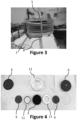
figure 3 représente un montage expérimental du réacteur, vu de côté ; - la
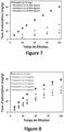
figure 4 représente le réacteur en pièces détachées, vu du dessus ; - la
figure 5 représente un schéma d'un système comprenant plusieurs réacteurs en parallèle, fonctionnant soit en adsorption, soit en régénération, de telle sorte que l'écoulement de l'eau soit continu ; - la
figure 6 représente un schéma d'un système comprenant plusieurs réacteurs en série, fonctionnant soit en adsorption, soit en régénération, de telle sorte que l'écoulement de l'eau soit continu et contrôlé par une unité de régulation au moyen de capteurs ; - la
figure 7 représente le taux d'adsorption d'un filtre vierge et de filtres non régénérés, en fonction du temps ; - la
figure 8 représente le taux d'adsorption d'un filtre vierge et de filtres régénérés, en fonction du temps ; - la
figure 9 représente un schéma de la désorption des polluants organiques et de leur dégradation ; - la
figure 10 représente des images effectuées au microscope électronique à balayage du tissu de charbon actif initial (A, E) et après 10 cycles de régénération (B, F). Les images C et D se concentrent sur la zone de rupture des fibres poreuses observées dans le matériau après 10 cycles de régénération ; - la
figure 11 représente une courbe de percée du filtre de fibres de charbon actif pour l'élimination de 50 mg/L d'acide clofibrique par une couche de fibres (résultats présentés par un triangle), 100 mg/L de phénolpar 8 couches de fibres (résultats présentés par un rond), 100 mg/L de phénolpar 10 couches de fibres (résultats présentés par un carré). Le ratio C / C0 représente le ratio entre la concentration à la sortie du filtre (C) et la concentration initiale de la solution (C0) ; - la
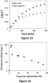
figure 12 représente l'évolution de la concentration en carbone organique total (COT) dans la solution, au cours des cycles de régénération entre chaque cycle d'adsorption ; - la
figure 13 représente l'évolution du taux d'adsorption de phénol (polluant modèle) sur les fibres de charbon actif (en g de phénol par g de fibres de charbon actif), en fonction du temps de filtration au cours de deux cycles d'adsorption de 290 min (test d'adsorption accéléré). Une étape de régénération électrochimique est réalisée in situ entre les 2 cycles ; - la
figure 14 représente l'évolution de la concentration en carbone organique total (COT) dans la solution, au cours du cycle de régénération ; - la
figure 15 représente un schéma explicatif de la problématique de rétention de gaz entre les électrodes au cours de l'électrolyse ; - la
figure 16 représente l'évolution de la différence de potentiel (DDP) de la cellule, dans une configuration lit de fibres charbon actif (cathode) / grille BDD serrée (anode). Le flux de la solution électrolytique au travers des électrodes est de 1000 L.m-2.h-2 (i.e. vitesse defiltration de 1 m.h-1) ; - la
figure 17 représente l'évolution de la différence de potentiel (DDP) de la cellule, dans une configuration lit de fibres charbon actif (cathode) / grille BDD serrée (anode). Le flux de la solution électrolytique au travers des électrodes est de 5000 L.m-2.h-2 (i.e. vitesse defiltration de 5 m.h-1) ; - la
figure 18 représente l'évolution de la différence de potentiel (DDP) de la cellule, dans une configuration lit de fibres charbon actif (cathode) / grille BDD serrée ou large (anode). Le flux de la solution électrolytique au travers des électrodes est de 1000 L.m-2.h-2 (i.e. vitesse defiltration de 1 m.h-1) ; - la
figure 19 représente l'évolution de la différence de potentiel (DDP) de la cellule, dans une configuration grille BDD serrée (anode) / lit de fibres charbon actif (cathode). Le flux de la solution électrolytique au travers des électrodes est de 1000 L.m-2.h-2 (i.e. vitesse defiltration de 1 m.h-1) ou de 5000 L.m-2.h-2 (i.e. vitesse defiltration de 5 m.h-1) ; - la
figure 20 représente l'évolution de la concentration en phénol lors de la régénération d'un filtre de 10 fibres de charbon actif (surface de 19,6 cm2) saturé par filtration d'une solution de 10 mg/L de phénol à 2 L/h. Une anode de type grille de BDD (taille de maille large) est placée en aval du filtre, une autre en amont. Une anode en BDD et une cathode en acier inoxydable sont placées dans le volume tampon pour la recirculation. L'intensité du courant est de 300 mA dans le volume tampon, et de 300 mA dans la chambre. La vitesse de filtration de la solution électrolytique est de 5 m/h. La solution électrolytique contient 50 mM de Na2SO4 et le pH est ajusté à 13 avec NaOH ; - la
figure 21 représente l'évolution de la concentration en carbone organique total (TOC) lors de la régénération d'un filtre de 10 fibres de charbon actif (surface de 19,6 cm2) saturé, par filtration d'une solution de 10 mg/L de phénol à 2 L/h. Une anode de type grille de BDD (taille de maille large) est placée en aval du filtre, une autre en amont. Une anode en BDD et une cathode en acier inoxydable sont placées dans le volume tampon pour la recirculation. L'intensité du courant est de 300 mA dans le volume tampon, et de 300 mA dans la chambre. La vitesse de filtration de la solution électrolytique est de 5 m/h. La solution électrolytique contient 50 mM de Na2SO4 et le pH est ajusté à 13 avec NaOH ; - la
figure 22 représente l'évolution de la courbe de percée de l'adsorption de 10 mg/L de phénol à un débit de 2 L/h sur un filtre de 10 fibres de charbon actif (surface de 19,6 cm2), sur le filtre neuf et après régénération. Les conditions opératoires de la régénération sont celles indiquées pour lesfigures 20 et21 .
- there
figure 1a represents a diagram of a cross section of a reactor used in adsorption mode; - there
figure 1b represents a diagram of a cross section of a reactor used in regeneration mode; - there
figure 2 represents an experimental setup of the reactor, seen from above; - there
Figure 3 represents an experimental setup of the reactor, seen from the side; - there
Figure 4 represents the reactor in separate parts, seen from above; - there
Figure 5 represents a diagram of a system comprising several reactors in parallel, operating either in adsorption or in regeneration, such that the flow of water is continuous; - there
Figure 6 represents a diagram of a system comprising several reactors in series, operating either in adsorption or in regeneration, such that the flow of water is continuous and controlled by a regulation unit using sensors; - there
Figure 7 represents the adsorption rate of a virgin filter and non-regenerated filters, as a function of time; - there
figure 8 represents the adsorption rate of a virgin filter and regenerated filters, as a function of time; - there
Figure 9 represents a diagram of the desorption of organic pollutants and their degradation; - there
Figure 10 represents scanning electron microscope images of the initial activated carbon tissue (A, E) and after 10 regeneration cycles (B, F). Images C and D focus on the breakage zone of the porous fibers observed in the material after 10 regeneration cycles; - there
Figure 11 represents a breakthrough curve of the activated carbon fiber filter for the removal of 50 mg/L of clofibric acid per one layer of fibers (results shown by a triangle), 100 mg/L of phenol per 8 layers of fibers ( results presented by a circle), 100 mg/L of phenol per 10 layers of fibers (results presented by a square). The ratio C / C 0 represents the ratio between the concentration at the filter outlet (C) and the initial concentration of the solution (C 0 ); - there
Figure 12 represents the evolution of the concentration of total organic carbon (TOC) in the solution, during the regeneration cycles between each adsorption cycle; - there
Figure 13 represents the evolution of the adsorption rate of phenol (model pollutant) on the activated carbon fibers (in g of phenol per g of activated carbon fibers), as a function of the filtration time during two adsorption cycles of 290 min (adsorption test accelerated). An electrochemical regeneration step is carried out in situ between the 2 cycles; - there
Figure 14 represents the evolution of the concentration of total organic carbon (TOC) in the solution, during the regeneration cycle; - there
Figure 15 represents an explanatory diagram of the problem of gas retention between the electrodes during electrolysis; - there
Figure 16 represents the evolution of the potential difference (DDP) of the cell, in an activated carbon fiber bed (cathode) / tight BDD grid (anode) configuration. The flow of the electrolytic solution through the electrodes is 1000 Lm -2 .h -2 (ie filtration speed of 1 mh -1 ); - there
Figure 17 represents the evolution of the potential difference (DDP) of the cell, in an activated carbon fiber bed (cathode) / tight BDD grid (anode) configuration. The flow of the electrolytic solution through the electrodes is 5000 Lm -2 .h -2 (ie filtration speed of 5 mh -1 ); - there
Figure 18 represents the evolution of the potential difference (DDP) of the cell, in an activated carbon fiber bed (cathode) / tight or wide BDD grid (anode) configuration. The flow of the electrolytic solution through the electrodes is 1000 Lm -2 .h -2 (ie filtration speed of 1 mh -1 ); - there
Figure 19 represents the evolution of the potential difference (DDP) of the cell, in a tight BDD grid (anode) / activated carbon fiber bed (cathode) configuration. The flow of the electrolytic solution through the electrodes is 1000 Lm -2 .h -2 (ie filtration speed of 1 mh -1 ) or 5000 Lm -2 .h -2 (ie filtration speed of 5 mh - 1 ); - there
Figure 20 represents the evolution of the phenol concentration during the regeneration of a filter of 10 activated carbon fibers (surface area of 19.6 cm 2 ) saturated by filtration of a solution of 10 mg/L of phenol at 2 L/ h. A BDD grid type anode (large mesh size) is placed downstream of the filter, another upstream. A BDD anode and a stainless steel cathode are placed in the buffer volume for recirculation. The current intensity is 300 mA in the buffer volume, and 300 mA in the chamber. The filtration speed of the electrolytic solution is 5 m/h. The electrolyte solution contains 50 mM Na 2 SO 4 and the pH is adjusted to 13 with NaOH; - there
Figure 21 represents the evolution of the concentration of total organic carbon (TOC) during the regeneration of a filter of 10 activated carbon fibers (surface area of 19.6 cm 2 ) saturated, by filtration of a solution of 10 mg/L of phenol at 2 L/h. A BDD grid type anode (large mesh size) is placed downstream of the filter, another upstream. A BDD anode and a stainless steel cathode are placed in the buffer volume for recirculation. The current intensity is 300 mA in the buffer volume, and 300 mA in the chamber. The filtration speed of the electrolytic solution is 5 m/h. The electrolyte solution contains 50 mM Na 2 SO 4 and the pH is adjusted to 13 with NaOH; - there
Figure 22 represents the evolution of the breakthrough curve for the adsorption of 10 mg/L of phenol at a flow rate of 2 L/h on a filter of 10 activated carbon fibers (surface area of 19.6 cm 2 ), on the filter new and after regeneration. The operating conditions for regeneration are those indicated for thefigures 20 And21 .
L'invention présente une première réalisation, un réacteur 1 permettant la filtration frontale en continu d'un fluide en écoulement pour l'adsorption de polluants sur un filtre 2, et une électrolyse pour la régénération du filtre 2 et l'élimination des polluants organiques,
le réacteur 1 comportant :
une chambre 3, avec au moins une entrée 4 délivrant un fluide dans la chambre 3 et au moins une sortie 5 permettant d'évacuer le fluide de la chambre 3 ;- des moyens d'alimentation en courant électrique ;
- un circuit de
circulation 8 d'un fluide à traiter par adsorption des polluants sur le filtre 2, permettant le passage du fluide à traiter au travers de la chambre 3 ; - un circuit de
recirculation 9 d'une solution électrolytique pour l'électrolyse, reliantla sortie 5 à l'entrée 4, et passant par unvolume tampon ouvert 9a permettant l'évacuation des bulles de gaz générées au cours de l'électrolyse ; - des moyens d'entrainement du fluide ;
- la totalité du fluide à traiter et de la solution électrolytique passant successivement au travers de l'ensemble des éléments de la chambre 3 qui comporte au moins :
un filtre 2 poreux, présentant au moins une couche de charbon actif permettant l'adsorption des polluants organiques lors de l'écoulement du fluide à traiter,
- la/les couches étant reliée(s) électriquement aux moyens d'alimentation en courant électrique, afin de polariser la/les couche(s) uniquement lors de l'électrolyse, le filtre 2 étant la cathode au cours de l'électrolyse et du passage de la solution électrolytique permettant la régénération du filtre et l'élimination des polluants organiques ;
une anode 6, en amont ou en aval du filtre 2, comprenant au moins une couche de matériau d'anode et des ouvertures permettant l'écoulement du fluide lors de la filtration et de la solution électrolytique lors de l'électrolyse,
- le matériau étant relié électriquement aux moyens d'alimentation du courant électrique, afin de le polariser en tant qu'anode au cours de l'électrolyse pour l'élimination des polluants organiques désorbés du filtre 2,
l'anode 6 et le filtre 2 sont placés horizontalement au sein de la chambre 3 placée verticalement, le circuit de recirculation 9 assurant un écoulement ascensionnel de la solution électrolytique au sein de la chambre 3, afin de favoriser l'évacuation des bulles de gaz formées au cours de l'électrolyse ;- le réacteur 1 fonctionnant suivant deux modes :
- en mode filtration continue d'un fluide par le circuit de
circulation 8 pour l'adsorption des polluants sur le filtre 2, sans alimentation électrique, sans recirculation de l'eau, - en mode électrolyse, pour la régénération du filtre 2 et l'élimination des polluants organiques, par application d'un courant électrique entre le filtre 2 utilisé en tant que cathode et
l'anode 6, avec recirculation continue de la solution électrolytique par le circuit derecirculation 9.
- en mode filtration continue d'un fluide par le circuit de
- a
chamber 3, with at least oneinlet 4 delivering a fluid into thechamber 3 and at least oneoutlet 5 allowing the fluid to be evacuated from thechamber 3; - electric current supply means;
- a
circulation circuit 8 of a fluid to be treated by adsorption of pollutants on thefilter 2, allowing the passage of the fluid to be treated through thechamber 3; - a
recirculation circuit 9 of an electrolytic solution for electrolysis, connectingoutlet 5 toinlet 4, and passing through anopen buffer volume 9a allowing the evacuation of gas bubbles generated during electrolysis; - means for driving the fluid;
- all of the fluid to be treated and the electrolytic solution passing successively through all of the elements of
chamber 3 which comprises at least:- a
porous filter 2, presenting at least one layer of activated carbon allowing the adsorption of organic pollutants during the flow of the fluid to be treated,
- a
- the layer(s) being electrically connected to the electric current supply means, in order to polarize the layer(s) only during electrolysis,
filter 2 being the cathode during electrolysis and the passage of the electrolytic solution allowing the regeneration of the filter and the elimination of organic pollutants;- an
anode 6, upstream or downstream of thefilter 2, comprising at least one layer of anode material and openings allowing the flow of the fluid during filtration and of the electrolytic solution during electrolysis,
- an
- the material being electrically connected to the electric current supply means, in order to polarize it as an anode during electrolysis for the elimination of organic pollutants desorbed from
filter 2, - the
anode 6 and thefilter 2 are placed horizontally within thechamber 3 placed vertically, therecirculation circuit 9 ensuring an upward flow of the electrolytic solution within thechamber 3, in order to promote the evacuation of the gas bubbles formed during electrolysis; - the
reactor 1 operating in two modes:- in continuous filtration mode of a fluid by the
circulation circuit 8 for the adsorption of pollutants on thefilter 2, without electrical power, without recirculation of the water, - in electrolysis mode, for the regeneration of
filter 2 and the elimination of organic pollutants, by application of an electric current between thefilter 2 used as cathode and theanode 6, with continuous recirculation of the electrolytic solution by thecircuit recirculation 9.
- in continuous filtration mode of a fluid by the
L'invention présente une deuxième réalisation, un réacteur 1 permettant la filtration en continu d'un fluide en écoulement pour l'adsorption de polluants sur un filtre 2, et la mise en place d'une électrolyse pour la régénération du filtre 2 et l'élimination des polluants organiques,
- le réacteur 1 comportant :
une chambre 3, avec au moins une entrée 4 délivrant un fluide dans la chambre 3 et au moins une sortie 5 permettant d'évacuer le fluide de la chambre 3 ;- des moyens d'alimentation en courant électrique d'au moins une anode 6 et au moins
un filtre 2 utilisé en tant que cathode ; - un circuit de
circulation 8 d'un fluide à traiter par adsorption des polluants sur le filtre 2, permettant le passage du fluide à traiter au travers de la chambre 3 ; - un circuit de
recirculation 9 d'une solution électrolytique pour l'électrolyse, reliantla sortie 5 à l'entrée 4, et passant par unvolume tampon ouvert 9a permettant l'évacuation des bulles générées au cours du procédé d'électrolyse,
- au sein duquel la totalité du fluide à traiter et/ou de la solution électrolytique passent successivement au travers de l'ensemble des éléments de la chambre 3 qui comporte au moins :
un filtre 2 comprenant au moins une couche de charbon actif, permettant l'écoulement d'un fluide liquide au travers, l'adsorption des polluants, le passage des bulles de gaz formées au cours de l'électrolyse, la/les couches étant reliée(s) électriquement aux moyens d'alimentation en courant électrique, afin de polariser la/les couche(s),le filtre 2 étant la cathode au cours de l'électrolyse permettant la régénération du filtre et l'élimination des polluants organiques.une anode 6 permettant l'écoulement d'un fluide liquide au travers, le passage des bulles de gaz formées au cours de l'électrolyse si elle est placée au-dessus du filtre 2, comprenant au moins une couche de matériau d'anode permettant de réaliser l'électrolyse de l'eau, le matériau étant relié électriquement aux moyens d'alimentation du courant électrique, afin de la polariser en tant qu'anode au cours de l'électrolyse pour l'élimination des polluants organiques désorbés du filtre 2,un élément séparateur 11, situé entre l'anode 6 et le filtre 2, permettant que le filtre 2 utilisé en tant que cathode et l'anode 6 soient reliées électriquement uniquement par la solution électrolytique au cours de l'électrolyse,
la chambre 3 fonctionnant suivant deux modes :- en mode filtration continue d'un fluide par le circuit de
circulation 8 pour l'adsorption des polluants sur le filtre 2, sans alimentation électrique, sans recirculation du fluide,l'anode 6 ne jouant alors aucun rôle, - en mode électrolyse, pour la régénération du filtre 2 et l'élimination des polluants organiques, par application d'un courant électrique entre le filtre 2 utilisé en tant que cathode et
l'anode 6, avec recirculation continue de la solution électrolytique par le circuit derecirculation 9.
- en mode filtration continue d'un fluide par le circuit de
-
reactor 1 comprising:- a
chamber 3, with at least oneinlet 4 delivering a fluid into thechamber 3 and at least oneoutlet 5 allowing the fluid to be evacuated from thechamber 3; - means for supplying electric current to at least one
anode 6 and at least onefilter 2 used as a cathode; - a
circulation circuit 8 of a fluid to be treated by adsorption of pollutants on thefilter 2, allowing the passage of the fluid to be treated through thechamber 3; - a
recirculation circuit 9 of an electrolytic solution for electrolysis, connectingoutlet 5 toinlet 4, and passing through anopen buffer volume 9a allowing the evacuation of bubbles generated during the electrolysis process,
- a
- in which all of the fluid to be treated and/or the electrolytic solution pass successively through all of the elements of
chamber 3 which comprises at least:- a
filter 2 comprising at least one layer of activated carbon, allowing the flow of a liquid fluid through, the adsorption of pollutants, the passage of gas bubbles formed during electrolysis, the layer(s) being connected (s) electrically to the electric current supply means, in order to polarize the layer(s), thefilter 2 being the cathode during the electrolysis allowing the regeneration of the filter and the elimination of organic pollutants. - an
anode 6 allowing the flow of a liquid fluid through, the passage of gas bubbles formed during electrolysis if it is placed above thefilter 2, comprising at least one layer of anode material allowing to carry out the electrolysis of water, the material being electrically connected to the means of supplying the electric current, in order to polarize it as an anode during the electrolysis for the elimination of organic pollutants desorbed from thefilter 2 , - a
separator element 11, located between theanode 6 and thefilter 2, allowing thefilter 2 used as cathode and theanode 6 to be electrically connected only by the electrolytic solution during electrolysis,
- a
-
chamber 3 operating in two modes:- in continuous filtration mode of a fluid by the
circulation circuit 8 for the adsorption of pollutants on thefilter 2, without electrical power, without recirculation of the fluid, theanode 6 then playing no role, - in electrolysis mode, for the regeneration of
filter 2 and the elimination of organic pollutants, by application of an electric current between thefilter 2 used as cathode and theanode 6, with continuous recirculation of the electrolytic solution by thecircuit recirculation 9.
- in continuous filtration mode of a fluid by the
L'invention présente une troisième réalisation, un réacteur 1 permettant la filtration en continu d'une eau en écoulement par adsorption de polluants organiques sur un filtre 2, et la régénération in-situ du filtre 2,
comportant :
une chambre 3 de filtration et de régénération, avec au moins une entrée 4 délivrant l'eau à traiter contenant des polluants organiques ou une solution électrolytique dans la chambre 3 de filtration et de régénération, et au moins une sortie 5 permettant d'évacuer l'eau filtrée de la chambre 3 de filtration et de régénération,- des moyens d'alimentation en courant électrique d'au moins une anode 6 et au moins une
cathode 7.
comprising:
- a filtration and
regeneration chamber 3, with at least oneinlet 4 delivering the water to be treated containing pollutants organic or an electrolytic solution in the filtration andregeneration chamber 3, and at least oneoutlet 5 making it possible to evacuate the filtered water from the filtration andregeneration chamber 3, - means for supplying electric current to at least one
anode 6 and at least onecathode 7.
Le réacteur 1 comporte également un circuit de circulation 8 de l'eau pour la filtration de l'eau à traiter, et un circuit de recirculation 9 d'une solution électrolytique pour la régénération du filtre, relié à un volume tampon ouvert 9a, utilisé pour l'évacuation des bulles générées lors de la régénération, reliant la sortie 5 à l'entrée 4.The
La chambre 3 de filtration et de régénération comporte :
un filtre 2 comprenant au moins une couche de fibres poreuses de charbon actif permettant la filtration de l'eau et l'adsorption des polluants organiques à leur surface,
et reliée(s) électriquement aux moyens d'alimentation en courant électrique, afin de polariser la/les couche(s),le filtre 2 étant lacathode 7 pour la régénération,l'anode 6 comprenant au moins une couche de matériau d'anode non-active pour réaliser une oxydation anodique des polluants organiques, un matériau d'anode non-actif étant défini comme ayant une surtension au dégagement d'oxygène supérieure à 0.4 V par rapport au potentiel thermodynamique d'évolution de l'oxygène,- le matériau étant relié électriquement aux moyens d'alimentation du courant électrique, afin de le polariser en tant qu'anode 6, pour la régénération,
- le matériau d'anode non-active étant configuré pour permettre l'écoulement de l'eau au travers,
- au moins un élément séparateur 11 situé entre l'anode 6 et la
cathode 7, permettant que lacathode 7et l'anode 6 soient reliées électriquement uniquement par la solution électrolytique
- a
filter 2 comprising at least one layer of porous activated carbon fibers allowing the filtration of water and the adsorption of organic pollutants on their surface,
and electrically connected to the electric current supply means, in order to polarize the layer(s), thefilter 2 being thecathode 7 for the regeneration, - the
anode 6 comprising at least one layer of non-active anode material to carry out anodic oxidation of organic pollutants, a non-active anode material being defined as having an overvoltage on the release of oxygen greater than 0.4 V per relation to the thermodynamic potential of evolution of oxygen,- the material being electrically connected to the means of supplying the electric current, in order to polarize it as an
anode 6, for regeneration, - the non-active anode material being configured to allow the flow of water therethrough,
- the material being electrically connected to the means of supplying the electric current, in order to polarize it as an
- at least one
separator element 11 located between theanode 6 and thecathode 7, allowing thecathode 7 and theanode 6 to be electrically connected only by the electrolytic solution
La chambre 3 de filtration et de régénération fonctionnant suivant deux modes :
- > en mode filtration continue de l'eau à traiter pour l'adsorption des polluants organiques de l'eau, sans courant électrique, sans recirculation de l'eau,
- > en mode régénération, par application d'un courant électrique entre la
cathode 7et l'anode 6, avec recirculation continue de la solution électrolytique,
- > in continuous filtration mode of the water to be treated for the adsorption of organic pollutants in the water, without electric current, without recirculation of the water,
- > in regeneration mode, by application of an electric current between the
cathode 7 and theanode 6, with continuous recirculation of the electrolytic solution,
L'invention montre pour la première fois un réacteur 1 continu capable de réaliser à la fois :
- une adsorption efficace en continu de polluants contenus dans l'eau grâce à l'utilisation d'un lit fixe de fibres de charbon actif,
- la régénération in situ dans le même réacteur de ces fibres de manière ponctuelle,
- l'élimination (dégradation / minéralisation) des polluants organiques accumulés à la surface des fibres de charbon actif, lors des étapes de régénération,
- continuous effective adsorption of pollutants contained in water thanks to the use of a fixed bed of activated carbon fibers,
- the in situ regeneration in the same reactor of these fibers on an ad hoc basis,
- the elimination (degradation/mineralization) of organic pollutants accumulated on the surface of the activated carbon fibers, during the regeneration stages,
Avantageusement, le fluide est un gaz ou un liquide tel qu'un liquide aqueux.Advantageously, the fluid is a gas or a liquid such as an aqueous liquid.
Plus avantageusement, le fluide est un liquide aqueux.More preferably, the fluid is an aqueous liquid.
Le réacteur 1 peut posséder une seule anode 6 en aval de la cathode 7 ou posséder deux anodes 6 : une première anode 6 se situant en amont de la cathode 7 et une seconde anode 6 se situant en aval de la cathode 7.The
Le réacteur 1 présente des parois d'extrémité de l'écoulement, avantageusement suffisamment éloignées de l'anode 6 et de la cathode 7, et/ou profilées en troncône (en tronc de cône, en entonnoir) : dans le but d'améliorer l'hydrodynamique et de favoriser l'évacuation des gaz et pouvant ainsi limiter la présence de bulles dans le réacteur.The
Les parois d'extrémité peuvent présenter un canal d'évacuation des gaz générés lors de l'oxydation anodique.The end walls may have a channel for evacuating gases generated during anodic oxidation.
Un réacteur présentant des parois d'extrémité de l'écoulement suffisamment éloignées de l'anode et de la cathode, et/ou profilées en troncône (tronc de cône) : pour favoriser l'hydrodynamique et l'évacuation des gaz.A reactor having end walls of the flow sufficiently distant from the anode and the cathode, and/or profiled in truncone (trunk of cone): to promote hydrodynamics and the evacuation of gases.
Avantageusement, le réacteur 1 présente un matériau d'anode 6, un circuit de recirculation 9 et une hydrodynamique permettant d'éviter la rétention des bulles de gaz générées au cours de l'électrolyse.Advantageously, the
Avantageusement, le réacteur 1 comprend :
le filtre 2 présentant des grains de charbon actif et/ou des fibres de charbon actif ;l'anode 6 présentant un matériau percé ou une grille sur laquelle est déposé le matériau d'anode.
- the
filter 2 having activated carbon grains and/or activated carbon fibers; - the
anode 6 having a pierced material or a grid on which the anode material is deposited.
Avantageusement, le réacteur 1 présentant un matériau d'anode 6, un filtre 2 en fibres de charbon actif et une composition de la solution électrolytique permettant d'améliorer la désorption des polluants et leur élimination au cours de l'électrolyse.Advantageously, the
Avantageusement, lorsqu'une électrode placée en aval d'une autre par rapport au sens d'écoulement du fluide au cours de la régénération est :
l'anode 6, comportant alors un matériau percé ou une grille avec ouvertures/mailles supérieures à 0,15 cm2 permettant le passage des bulles de gaz formées au cours de l'électrolyse ; oule filtre 2 utilisé en tant que cathode, alors les moyens d'entrainement du fluide sont configurés pour permettre d'exercer une pression sur cette électrode aval, de façon à réaliser le passage des bulles de gaz formées au cours de l'électrolyse, au travers de cette électrode aval.
- the
anode 6, then comprising a pierced material or a grid with openings/meshes greater than 0.15 cm 2 allowing the passage of gas bubbles formed during electrolysis; Or - the
filter 2 used as a cathode, then the fluid driving means are configured to allow pressure to be exerted on this downstream electrode, so as to achieve the passage of the gas bubbles formed during the electrolysis, through through this downstream electrode.
Avantageusement, la grille a des ouvertures/mailles supérieures à 0,20 cm2 ; 0,25 cm2 ; 0,30 cm2 ; 0,35 cm2 ; 0,40 cm2 ; 0,45 cm2 ; ou 0,50 cm2.Advantageously, the grid has openings/meshes greater than 0.20 cm 2 ; 0.25 cm 2 ; 0.30 cm 2 ; 0.35cm2 ; 0.40 cm 2 ; 0.45cm2 ; or 0.50 cm 2 .
Dans une autre incarnation, le réacteur 1 est un réacteur 1 colonne qui peut présenter des éléments séparateurs 11 entre l'anode 6 et la cathode 7, et dont l'écoulement présente un flux ascendant. Ces éléments séparateurs doivent permettre que l'anode et la cathode soient reliées électriquement uniquement par la solution électrolytique. Les moyens d'alimentation en courant électrique ne doivent pas affecter l'étanchéité du réacteur 1 fermé.In another incarnation, the
Avantageusement, la chambre 3 comprend plusieurs couples d'anode 6 / filtre 2, montés en série, les deux faces d'une électrode pouvant être polarisées lors de l'électrolyse.Advantageously, the
Avantageusement, au moins une anode, au moins une cathode et des moyens d'alimentation en courant électrique sont comprises dans le volume tampon ouvert 9a, afin de favoriser l'élimination des polluants au cours de l'électrolyse, telle qu'une anode comprenant au moins une couche de diamant dopé au bore ou en oxyde de titane sous-stoechiométrique.Advantageously, at least one anode, at least one cathode and means for supplying electric current are included in the
Avantageusement, des séparateurs en PMMA (polyméthacrylate de méthyle) ou en PTFE (polytétrafluoroéthylène) sont utilisés et des fils et/ou des feuilles de titane et/ou de platine sont utilisés pour l'alimentation électrique.Advantageously, separators made of PMMA (polymethyl methacrylate) or PTFE (polytetrafluoroethylene) are used and wires and/or sheets of titanium and/or platinum are used for the electrical power supply.
Avantageusement, des joints sont utilisés pour que l'ensemble des éléments présents dans le réacteur 1 permettent l'écoulement au travers des matériaux d'anode et de cathode, sans zone de court-circuit (exemple : effets de bords).Advantageously, seals are used so that all of the elements present in the
La couche anodique du réacteur 1 est avantageusement déposée sur un support avec des ouvertures, dont les ouvertures possèdent une dimension permettant l'écoulement de l'eau et l'évacuation des bulles de gaz générées au cours de l'électrolyse.The anodic layer of
La couche d'anode non-active est un matériau pouvant permettre l'écoulement de l'eau et l'évacuation des bulles de gaz générées au cours de l'électrolyse.The non-active anode layer is a material that can allow the flow of water and the evacuation of gas bubbles generated during electrolysis.
Avantageusement, la couche d'anode non-active et/ou le support sont poreux, l'anode 6 peut soit être un matériau non-actif à 100% soit être un dépôt sur un support.Advantageously, the non-active anode layer and/or the support are porous, the
Dans une incarnation possible, la couche d'anode non-active et/ou le support présente un quadrillage tel qu'une grille, et/ou est percé.In one possible embodiment, the non-active anode layer and/or the support has a grid such as a grid, and/or is pierced.
Dans une réalisation possible, le réacteur 1 possède une armature 12 pouvant contenir toutes les couches, le réacteur 1 pouvant se démonter, les couches à l'intérieur peuvent être changées pour remplacer les couches.In one possible embodiment, the
Avantageusement, les grilles sont choisies au lieu des anodes percées afin d'améliorer l'hydrodynamique au sein de la cellule.Advantageously, the grids are chosen instead of the drilled anodes in order to improve the hydrodynamics within the cell.
Avantageusement, la couche d'anode non active et/ou le support présente un espacement entre ses ouvertures configuré pour limiter la présence de bulles entre l'anode 6 et la cathode 7, et permettre notamment l'évacuation des gaz (H2, O2) formés lors de l'oxydation anodique.Advantageously, the non-active anode layer and/or the support has a spacing between its openings configured to limit the presence of bubbles between the
Par exemple, la surface du support (d'une grille) est de 20cm2.For example, the surface area of the support (of a grid) is 20cm 2 .
Avantageusement, la surface des trous est comprise entre 20 et 100 mm2, plus précisément entre 30 et 60 mm2.Advantageously, the surface of the holes is between 20 and 100 mm 2 , more precisely between 30 and 60 mm 2 .
Avantageusement, le support comporte entre 60 et 100 trous, plus précisément entre 70 et 90.Advantageously, the support has between 60 and 100 holes, more precisely between 70 and 90.
Dans une incarnation possible, la couche d'anode est un matériau poreux, pouvant être une mousse de TiOx ou une membrane en TiOx. La mousse pouvant avoir des pores avec une taille comprise entre 60 et 300 µm. La membrane pouvant avoir des pores avec une taille comprise entre 0,1 et 5 µm.In one possible incarnation, the anode layer is a porous material, which may be a TiOx foam or a TiOx membrane. The foam can have pores with a size between 60 and 300 µm. The membrane can have pores with a size between 0.1 and 5 µm.
Avantageusement, lorsque la couche d'anode est une mousse de TiOx ou une membrane en TiOx électrode placée en aval d'une autre électrode par rapport au sens d'écoulement du fluide au cours de la régénération, alors les moyens d'entrainement du fluide sont configurés pour permettre d'exercer une pression sur cette électrode aval de façon à réaliser le passage des bulles de gaz formées au cours de l'électrolyse, au travers de cette électrode aval.Advantageously, when the anode layer is a TiOx foam or a TiOx membrane electrode placed downstream of another electrode with respect to the direction of flow of the fluid during regeneration, then the means for driving the fluid are configured to allow pressure to be exerted on this downstream electrode so as to cause the gas bubbles formed during electrolysis to pass through this downstream electrode.
Dans un montage possible, le réacteur 1 présente dans un corps 12, montés en série :
- un élément d'entrée de l'eau,
- une première couche d'anode non active en appui sur un premier support,
- un premier élément séparateur 11 non conducteur, avec joint d'étanchéité en contact au moins sur une
cathode 7, - la cathode présentant plusieurs couches de fibres poreuses de charbon actif,
- un deuxième élément séparateur 11 non conducteur, avec joint d'étanchéité en contact au moins sur la
cathode 7, - une deuxième couche d'anode non active reposant sur un deuxième support,
- un élément de sortie de l'eau.
- a water inlet element,
- a first non-active anode layer resting on a first support,
- a first
non-conductive separator element 11, with seal in contact at least on onecathode 7, - the cathode having several layers of porous activated carbon fibers,
- a second
non-conductive separator element 11, with seal in contact at least on thecathode 7, - a second non-active anode layer resting on a second support,
- a water outlet element.
Selon l'invention, le réacteur comprend une unité de régulation 14 reliée à des électrovannes des circuits de circulation 8 et de recirculation 9, aux moyens d'entrainement du fluide et aux moyens d'alimentation en courant électrique, de façon à pouvoir mettre en place le mode de fonctionnement filtration ou électrolyse, par action de l'unité de régulation 14 sur les circuits de circulation 8 et de recirculation 9 ainsi que sur les moyens d'entrainement du fluide et sur les moyens d'alimentation en courant électrique.According to the invention, the reactor comprises a
Avantageusement, l'unité de régulation est apte à inverser le sens de la circulation de l'écoulement dans le réacteur entre le passage du fluide dans le réacteur en mode filtration, et le passage de la solution électrolytique en mode électrolyse.Advantageously, the regulation unit is able to reverse the direction of circulation of the flow in the reactor between the passage of the fluid in the reactor in filtration mode, and the passage of the electrolytic solution in electrolysis mode.
Avantageusement, l'unité de régulation est reliée à un capteur de mesure de la concentration en polluants au niveau de la sortie 5, le mode électrolyse étant mis en place lorsque la concentration en polluants passe au-dessus d'une valeur donnée, le mode filtration étant mis en place lorsque la concentration en polluants passe en-dessous d'une valeur donnée.Advantageously, the regulation unit is connected to a sensor for measuring the concentration of pollutants at
Avantageusement, les moyens d'entrainement du fluide sont configurés pour permettre au circuit de recirculation 9 d'atteindre une vitesse de filtration du fluide au travers du filtre 2 supérieure à 2 m/h.Advantageously, the fluid driving means are configured to allow the
Avantageusement, la vitesse de filtration du fluide est supérieure à 3m/h ; 4m/h ; 5m/h ; 6m/h ; 7m/h ; 8m/h ; 9m/h ; ou 10m/h.Advantageously, the filtration speed of the fluid is greater than 3 m/h; 4m/h; 5m/h; 6m/h; 7m/h; 8m/h; 9m/h; or 10m/h.
Le réacteur 1 possède deux modes d'utilisations, avantageusement son utilisation la plus commune est le mode filtration.The
Par rapport à une solution technique d'électro-oxydation conventionnelle (traitement en continu d'un effluent), l'invention présente les avantages suivants :
- préconcentration des polluants sur les fibres de charbon actif avant application ponctuelle de l'électro-oxydation ; cette étape permet d'améliorer l'efficacité énergétique du procédé et donc de réduire la consommation énergétique ;
- possibilité de contrôler la composition de la solution électrolytique afin de réduire la production de sous-produits toxiques (exemple : sous-produits chlorés lors de l'utilisation d'une solution conventionnelle d'électro-oxydation d'un effluent contenant des ions chlorures) ;
- possibilité de réduire la consommation d'électrolyte nécessaire au passage du courant, grâce à la mise en place de l'électro-oxydation uniquement de manière ponctuelle
- preconcentration of pollutants on activated carbon fibers before occasional application of electro-oxidation; this step makes it possible to improve the energy efficiency of the process and therefore to reduce energy consumption;
- possibility of controlling the composition of the electrolytic solution in order to reduce the production of toxic by-products (example: chlorinated by-products when using a conventional solution for the electro-oxidation of an effluent containing chloride ions);
- possibility of reducing the consumption of electrolyte necessary for the passage of current, thanks to the implementation of electro-oxidation only occasionally
L'utilisation d'un lit de fibres de charbon actif permet d'assurer une filtration efficace de l'eau, tout en maintenant une faible épaisseur du lit de filtration.The use of a bed of activated carbon fibers ensures effective water filtration, while maintaining a low thickness of the filtration bed.
Des exemples de résultats sont présentés dans la
Dans une réalisation possible, la au moins une couche de charbon actif est formée de fibres de charbon actif.In one possible embodiment, the at least one layer of activated carbon is formed of activated carbon fibers.
Dans une autre réalisation possible, la au moins une couche de charbon actif est formée de grains de charbon actif.In another possible embodiment, the at least one layer of activated carbon is formed of grains of activated carbon.
Par rapport à une solution technique d'adsorption sur charbon actif conventionnelle, l'invention présente les avantages suivants :
- possibilité de bénéficier des caractéristiques des fibres de charbon actif (afin de pallier les limitations du grain et de la poudre) et de mettre en place des réacteurs compacts (faible épaisseur des lits de filtration) ;
- possibilité de réduire la quantité de matériau adsorbant utilisée (grâce à la régénération).
- possibility of benefiting from the characteristics of activated carbon fibers (in order to overcome the limitations of grain and powder) and of setting up compact reactors (low thickness of the filtration beds);
- possibility of reducing the quantity of adsorbent material used (thanks to regeneration).
Le réacteur 1 peut présenter plusieurs couches de fibres de charbon actif superposées.
Avantageusement, les fibres poreuses se présentent sous forme de feutre ou de tissu.Advantageously, the porous fibers are in the form of felt or fabric.
Avantageusement, la au moins une couche de charbon actif présente une surface spécifique supérieure à 600 m2.g-1 et les fibres poreuses présentent une porosité de sorte que plus de 30% du volume poreux de chacune des fibres poreuses est constitué par des pores de taille inférieure à 2 nm.Advantageously, the at least one layer of activated carbon has a specific surface area greater than 600 m2.g-1 and the porous fibers have a porosity such that more than 30% of the pore volume of each of the porous fibers is constituted by pores of size less than 2 nm.
La couche de fibres de charbon actif possède une épaisseur pouvant être comprise entre 0,3 et 20 cm (l'épaisseur de cette couche dépend du nombre de sous couche de fibres de charbons utilisées).

Avantageusement, la vitesse de filtration (ratio entre le débit d'eau et la surface du filtre 2) est comprise entre 0,2 m/h et 5 m/h, en mode filtration, et entre 2 et 20 m/h en mode régénération.Advantageously, the filtration speed (ratio between the water flow and the surface of the filter 2) is between 0.2 m/h and 5 m/h, in filtration mode, and between 2 and 20 m/h in mode regeneration.
Dans une incarnation possible, la sortie 5 possède une forme conique (pointe en aval du courant), pour faciliter l'évacuation des gaz.In a possible incarnation,
Dans une incarnation possible, l'entrée 4 possède une forme conique (pointe en amont du courant), pour répartir l'eau sur la surface de la/ des couche(s) de fibres de charbon actifs.In a possible incarnation, the
Dans une autre réalisation, le réacteur 1 possède une nouvelle sortie 5 située entre l'anode 6 et la cathode 7, avantageusement utilisée lors de la régénération. Dans cette incarnation, la solution électrolytique s'écoule de l'entrée 4 vers la nouvelle sortie 5, et de l'ancienne sortie 5 (devenant une nouvelle entrée 4) vers la nouvelle sortie 5.In another embodiment, the
Dans une autre réalisation, un capteur 13 est ajouté, pour permettre de mesurer la quantité de polluants organiques à l'entrée 4 et à la sortie 5, afin d'établir un pourcentage d'efficacité de filtration.In another embodiment, a
Avantageusement, le réacteur 1 passe en mode régénération quand le pourcentage d'efficacité de filtration atteint de préférence moins de 95%.Advantageously, the
Avantageusement, le seuil, permettant un changement automatique de mode d'utilisation, est modulable.Advantageously, the threshold, allowing an automatic change of mode of use, is adjustable.
Dans ce mode d'utilisation, la circulation d'eau entrante (à filtrer) est coupée, afin d'utiliser une solution électrolytique recirculée en continu. La solution électrolytique provient d'un volume tampon ouvert.In this mode of use, the circulation of incoming water (to be filtered) is cut off, in order to use a continuously recirculated electrolytic solution. The electrolyte solution comes from an open buffer volume.
Afin de procéder à la régénération du filtre 2 (couches de charbons actifs), un courant électrique passe dans la au moins une couche de charbon actif et dans la couche de matériau anodique, formant respectivement une cathode 7 et une anode 6.In order to regenerate the filter 2 (layers of activated carbon), an electric current passes through the at least one layer of activated carbon and into the layer of anodic material, respectively forming a
Grâce à ce mode de régénération et à l'invention :
- possibilité de régénérer plusieurs fois de manière in situ les fibres de charbon actif, afin de recouvrer la capacité d'adsorption initiale, comme le démontre la
figure 8 ; - minimisation de la manutention et élimination du transport du matériau adsorbant usagé ;
- possibilité d'éliminer complètement les polluants (minéralisation) ;
- application ponctuelle du procédé d'électro-oxydation (après l'adsorption) ; cela permet de fortement réduire la consommation d'électrolyte (sels pouvant être ajoutés pour augmenter la conductivité de l'eau et réduire la consommation énergétique), par rapport à une application en continu du procédé d'électro-oxydation. La forte concentration en polluant sur les fibres de charbon actif améliore aussi l'efficacité énergétique du procédé d'électro-oxydation, par rapport à une application conventionnelle en continu sur l'eau à traiter moins concentrée. La composition de l'électrolyte peut-être choisie afin de sélectionner les espèces oxydantes qui seront formées, et éviter la formation de composés toxiques.
- possibility of regenerating the activated carbon fibers several times in situ, in order to recover the initial adsorption capacity, as demonstrated by
figure 8 ; - minimization of handling and elimination of transport of used adsorbent material;
- possibility of completely eliminating pollutants (mineralization);
- one-off application of the electro-oxidation process (after adsorption); this makes it possible to significantly reduce the consumption of electrolyte (salts that can be added to increase the conductivity of the water and reduce energy consumption), compared to a continuous application of the electro-oxidation process. The high concentration of pollutant on the activated carbon fibers also improves the energy efficiency of the electro-oxidation process, compared to a conventional continuous application on the less concentrated water to be treated. The composition of the electrolyte can be chosen in order to select the oxidizing species that will be formed, and avoid the formation of toxic compounds.
La régénération fonctionne par différents mécanismes :
- désorption des polluants de la
cathode 7, cette désorption est accélérée par la polarisation en tant quecathode 7 du matériau et le pH local élevé au niveau de la cathode 7 (interactions électrostatiques) ; - formation d'espèces oxydantes, principalement à l'anode 6 (principalement radicaux hydroxyles, persulfates, radicaux sulfates), mais aussi à la cathode (peroxyde d'hydrogène, radicaux sulfates), pour la dégradation et la minéralisation des polluants désorbés, comme le démontre la
figure 9 ; - dégradation et minéralisation dans la solution des polluants désorbés permettant un décalage continu de l'équilibre de sorption, et donc la désorption continue des composés adsorbés ;
- oxydation directe des composés adsorbés par les espèces oxydantes formées électrochimiquement.
- desorption of pollutants from
cathode 7, this desorption is accelerated by the polarization ascathode 7 of the material and the high local pH at the level of cathode 7 (electrostatic interactions); - formation of oxidizing species, mainly at anode 6 (mainly hydroxyl radicals, persulfates, sulfate radicals), but also at the cathode (hydrogen peroxide, sulfate radicals), for the degradation and mineralization of desorbed pollutants, such as demonstrates the
Figure 9 ; - degradation and mineralization in the solution of the desorbed pollutants allowing a continuous shift in the sorption equilibrium, and therefore the continuous desorption of the adsorbed compounds;
- direct oxidation of adsorbed compounds by electrochemically formed oxidizing species.
Pour effectuer la régénération, une solution électrolytique circule dans la chambre 3 de filtration. La solution électrolytique circule dans le circuit de recirculation 9, la solution n'est pas jetée, elle est réutilisée et tourne en boucle dans le circuit de recirculation 9 et dans la chambre 3, jusqu'à que le filtre 2 ne possède plus qu'une quantité limitée de polluants organiques.To carry out the regeneration, an electrolytic solution circulates in the
Dans une incarnation possible, le circuit de recirculation 9 possède un récipient comprenant un volume tampon ouvert 9a de la solution électrolytique. Lors de la régénération du filtre, le récipient fournit la solution électrolytique du volume tampon 9a qui circule de l'entrée 4 de la chambre de filtration 3, et le récipient reçoit la solution électrolytique par la sortie 5 de la chambre 3 de filtration. Les bulles formées lors de la régénération sont transportées par la solution électrolytique lors de son écoulement dans le circuit de recirculation 9. Les bulles sont évacuées dans le volume tampon 9a, avec un moyen de renouvellement de l'air ou par contact direct avec l'air.In a possible incarnation, the
Dans une incarnation possible, le volume tampon 9a possède une anode 6 et une cathode 7, participant à l'élimination par électro-oxydation des composés désorbés (les polluants organiques) lors de la régénération, permettant de réduire le temps de régénération. Différents matériaux d'électrodes peuvent être utilisés, selon la nature des composés désorbés à éliminer.In a possible incarnation, the
Dans un exemple d'utilisation, un capteur 13 permet de suivre la minéralisation des polluants désorbés, au cours des cycles de régénération, la
Avantageusement, le capteur 13 mesure l'absorbance UV de l'eau à l'entrée 4 et à la sortie 5.Advantageously, the
Dans une autre incarnation possible, le capteur 13 mesure la concentration en Carbone Organique Total (COT) de l'eau.In another possible incarnation, the
Avantageusement, la solution électrolytique est une solution de sulfate de sodium à 50 mM. Cette solution permet d'éviter la formation de sous-produits toxiques, tel que c'est le cas en présence de chlorures.Advantageously, the electrolyte solution is a 50 mM sodium sulfate solution. This solution makes it possible to avoid the formation of toxic by-products, as is the case in the presence of chlorides.
Avantageusement, la solution électrolytique contient uniquement du sulfate de sodium.Advantageously, the electrolyte solution contains only sodium sulfate.
Plus avantageusement, la solution électrolytique est sans fer et/ou sans oxygène.More advantageously, the electrolyte solution is iron-free and/or oxygen-free.
Avantageusement, le pH de la solution électrolytique est ajusté, pour améliorer la désorption des polluants.Advantageously, the pH of the electrolytic solution is adjusted to improve the desorption of pollutants.
Avantageusement, le pH de la solution électrolytique est ajusté, pour améliorer la désorption des polluants à un pH supérieur à 8 ; 9 ; 10 ; 11 ; 12 ; 13.Advantageously, the pH of the electrolytic solution is adjusted to improve the desorption of pollutants at a pH greater than 8; 9; 10; 11; 12; 13.
Avantageusement, des ions peroxymonosulfate et/ou peroxodisulfate sont produits à l'anode, par oxydation des ions sulfates, pour favoriser la régénération du filtre et/ou l'élimination des polluants organiques.Advantageously, peroxymonosulfate and/or peroxodisulfate ions are produced at the anode, by oxidation of the sulfate ions, to promote the regeneration of the filter and/or the elimination of organic pollutants.
Avantageusement, des ions peroxymonosulfate et/ou peroxodisulfate sont activés au niveau du filtre en charbon actif utilisé en tant que cathode, pour former des espèces oxydantes permettant de favoriser la régénération du filtre et/ou l'élimination des polluants organiques.Advantageously, peroxymonosulfate and/or peroxodisulfate ions are activated at the activated carbon filter used as cathode, to form oxidizing species making it possible to promote the regeneration of the filter and/or the elimination of organic pollutants.
Avantageusement, des ions peroxymonosulfate et/ou peroxodisulfate sont ajoutés dans la solution électrolytique, pour favoriser la régénération du filtre et/ou l'élimination des polluants organiques.Advantageously, peroxymonosulfate and/or peroxodisulfate ions are added to the electrolytic solution, to promote the regeneration of the filter and/or the elimination of organic pollutants.
Dans une autre incarnation, la solution électrolytique contient source de fer et de l'air barboté afin de promouvoir, en plus de l'oxydation anodique, le procédé électro-Fenton (formation d'H2O2 et de Fe2+ à la cathode permettant la formation de radicaux hydroxyles par la réaction de Fenton).In another incarnation, the electrolytic solution contains iron source and bubbled air in order to promote, in addition to anodic oxidation, the electro-Fenton process (formation of H 2 O 2 and Fe 2+ at the cathode allowing the formation of hydroxyl radicals by the Fenton reaction).
L'invention possède des avantages, notamment une grande efficacité du procédé attribuée à
- (i) l'oxydation directe du phénol (PH) adsorbé par les radicaux hydroxyles générés,
- (ii) le déplacement continu de l'équilibre d'adsorption dû à l'oxydation des composés organiques dans la solution et à la réaction à l'anode et
- (iii) l'augmentation locale du pH au niveau de la
cathode 7 conduisant à des interactions électrostatiques répulsives.
- (i) the direct oxidation of phenol (PH) adsorbed by the hydroxyl radicals generated,
- (ii) the continuous shift of the adsorption equilibrium due to the oxidation of organic compounds in the solution and the reaction at the anode and
- (iii) the local increase in pH at
cathode 7 leading to repulsive electrostatic interactions.
Un exemple de possible constitution du réacteur 1 est un empilement d'une anode 6, comme illustré
Un exemple possible d'une configuration est constitué d'un élément de polyméthacrylate de méthyle non conducteur, d'une grille de Nb recouverte de diamant dopé au bore, puis d'une couche en téflon non conducteur, une couche de fibres de charbon actif, une couche en téflon non conducteur, une grille de Nb recouverte de diamant dopé au bore, enfin un élément de polyméthacrylate de méthyle non conducteur, le tout entouré par un carter en polyméthacrylate de méthyle.A possible example of a configuration consists of a non-conductive polymethyl methacrylate element, a Nb grid covered with boron-doped diamond, then a non-conductive Teflon layer, a layer of activated carbon fibers , a non-conductive Teflon layer, a Nb grid covered with boron-doped diamond, finally a non-conductive polymethyl methacrylate element, all surrounded by a polymethyl methacrylate casing.
Un exemple de conditions opératoires du réacteur 1 au cours de la régénération :
- utilisation d'une configuration « sandwich », avec deux électrodes planes percées en diamant dopé au bore de chaque côté du tissu de charbon actif à régénérer ;
- conditions opératoires : I = 750 mA ; débit = 0.9 L/h ; volume de la solution utilisée et continuellement recirculée = 150 mL ; pH = 3 ; [Na2SO4] = 50 mM ; [Fe] = 0.15 mM ; barbotage continu d'air dans la solution ; temps de traitement de 3 h.
- use of a “sandwich” configuration, with two flat drilled boron-doped diamond electrodes on each side of the activated carbon fabric to be regenerated;
- operating conditions: I = 750 mA; flow = 0.9 L/h; volume of the solution used and continuously recirculated = 150 mL; pH = 3; [Na2SO4] = 50 mM; [Fe] = 0.15 mM; continuous bubbling of air into the solution; processing time of 3 hours.
Conditions opératoires au cours de la filtration : 1 seule couche de fibres de charbon actif (diamètre = 5,5 cm) ; débit = 0.9 L/h ; concentration en acide clofibrique = 55 mg/L.Operating conditions during filtration: 1 single layer of activated carbon fibers (diameter = 5.5 cm); flow = 0.9 L/h; clofibric acid concentration = 55 mg/L.
Un autre exemple de conditions opératoires au cours de la régénération :
- utilisation d'une configuration « sandwich », avec deux électrodes de type grille en diamant dopé au bore de chaque côté du lit de fibres de charbon actif à régénérer (10 couches), séparés par des couches de téflon non conducteur ;
- conditions opératoires : I = 600 mA ; débit = 4.0 L/h ; volume de la solution utilisée et continuellement recirculée = 400 mL ; pH naturel ; [Na2SO4] = 50 mM ; [Fe] = 0 mM ; pas de barbotage ; temps de traitement 36 h.
- use of a “sandwich” configuration, with two boron-doped diamond grid-type electrodes on each side of the bed of activated carbon fibers to be regenerated (10 layers), separated by layers of non-conductive Teflon;
- operating conditions: I = 600 mA; flow = 4.0 L/h; volume of the solution used and continuously recirculated = 400 mL; natural pH; [Na2SO4] = 50 mM; [Fe] = 0 mM; no splashing; processing time 36 hours.
Conditions opératoires au cours de la filtration : 10 couches de fibres de charbon actif (diamètre = 5,5 cm) ; débit = 2.0 L/h ; concentration en phénol = 100 mg/L.Operating conditions during filtration: 10 layers of activated carbon fibers (diameter = 5.5 cm); flow = 2.0 L/h; phenol concentration = 100 mg/L.
Un autre exemple de conditions opératoires au cours de la régénération :
- utilisation d'une configuration « sandwich », avec deux électrodes de type grille en diamant dopé au bore (BDD diamètre 5 cm, mailles larges) de chaque côté du lit de fibres de charbon actif à régénérer (10 couches, diamètre 5 cm), séparés par des couches de polyméthacrylate de méthylenon conducteur ;
- une anode en diamant dopé au bore et une cathode en acier inoxydable sont placées dans le volume tampon pour la recirculation. L'intensité du courant est de 300 mA dans le volume tampon et de 300 mA dans la chambre. La vitesse de filtration de la solution électrolytique est de 5 m/h. La solution électrolytique contient 50 mM de Na2SO4 et le pH est ajusté à 13 avec NaOH.
- conditions opératoires : I = 300 mA dans la chambre et 1 = 300 mA dans le volume tampon pour la recirculation; débit = 10.0 L/h ; volume de la solution utilisée et continuellement recirculée = 2 L ;
pH 13 ; [Na2SO4] = 50 mM ; [Fe] = 0 mM ; pas de barbotage. - conditions opératoires au cours de la filtration : 10 couches de fibres de charbon actif (diamètre = 5 cm) ; débit = 2.0 L/h ; concentration en phénol = 10 mg/L.
- use of a “sandwich” configuration, with two boron-doped diamond grid-type electrodes (
BDD diameter 5 cm, large mesh) on each side of the bed of activated carbon fibers to be regenerated (10 layers,diameter 5 cm), separated by layers of non-conductive polymethylene methacrylate; - a boron-doped diamond anode and a stainless steel cathode are placed in the buffer volume for recirculation. The intensity of current is 300 mA in the buffer volume and 300 mA in the chamber. The filtration speed of the electrolytic solution is 5 m/h. The electrolyte solution contains 50 mM Na 2 SO 4 and the pH is adjusted to 13 with NaOH.
- operating conditions: I = 300 mA in the chamber and 1 = 300 mA in the buffer volume for recirculation; flow = 10.0 L/h; volume of the solution used and continuously recirculated = 2 L;
pH 13; [Na2SO4] = 50 mM; [Fe] = 0 mM; no splashing. - operating conditions during filtration: 10 layers of activated carbon fibers (diameter = 5 cm); flow = 2.0 L/h; phenol concentration = 10 mg/L.
Lors d'études avec des conditions opératoires possibles de l'invention, les résultats présentés sur la
Le réacteur 1 décrit dans l'invention peut être utilisé dans un système 10 permettant la filtration de l'eau comprenant au moins un réacteur 1, et des moyens d'écoulement de l'eau reliés à l'entrée 4 et à la sortie 5.The
Avantageusement, les circuits de recirculation 9 du fluide des réacteurs 1 sont reliés, de façon à présenter un volume tampon ouvert 9a commun.Advantageously, the
Avantageusement, les réacteurs 1 sont placés en série ou en parallèle, par rapport à l'écoulement du fluide à traiter.Advantageously, the
Les moyens d'écoulement peuvent être configurés, et/ou le réacteur 1 est pivoté de 180 degrés, pour que l'écoulement soit inversé entre le mode adsorption et le mode régénération.The flow means can be configured, and/or the
Avantageusement, les moyens d'écoulement sont configurés pour que la vitesse de filtration (ratio entre le débit d'eau et la surface du filtre 2) soit comprise entre 0,2 m/h et 5 m/h, en mode filtration, et entre 0,2 et 20 m/h en mode régénération.Advantageously, the flow means are configured so that the filtration speed (ratio between the water flow and the surface of the filter 2) is between 0.2 m/h and 5 m/h, in filtration mode, and between 0.2 and 20 m/h in regeneration mode.
Dans une incarnation possible, plusieurs réacteurs 1 colonnes sont disposés de façon à pouvoir être en mode régénération dans au moins un réacteur 1, pendant que les autres réacteurs 1 sont en mode adsorption.In one possible incarnation, several 1-column reactors are arranged so as to be able to be in regeneration mode in at least one
Les réacteurs 1 peuvent être mis en parallèle (
Avantageusement, c'est la qualité de l'eau globale en sortie qui est mesurée, pour pouvoir mesurer la quantité de polluants organiques en sortie. Avantageusement, lorsque la qualité de l'eau en sortie baisse, on réactive un filtre propre/régénéré (qui était jusqu'alors plus utilisé pour l'adsorption), et on passe en régénération un filtre sale.Advantageously, it is the quality of the overall water at the outlet which is measured, in order to be able to measure the quantity of organic pollutants at the outlet. Advantageously, when the quality of the water at the outlet drops, we reactivates a clean/regenerated filter (which was previously more used for adsorption), and a dirty filter is regenerated.
Avantageusement, le système 10 possède plusieurs capteurs 13. Le système 10 peut avoir un capteur 13 à l'entrée 4 du système 10 et un second capteur 13 à la sortie 5 du système 10.Advantageously, the
Dans une autre incarnation, le système 10 possède un capteur 13 à chaque entrée 4 et à chaque sortie 5 des réacteurs 1 présents dans le système 10.In another incarnation, the
Avantageusement, toutes les entrées 4 et toutes les sorties 5 des réacteurs 1 présents dans le système 10, sont reliées au volume tampon 9a, formant ainsi le circuit de recirculation.Advantageously, all the
Avantageusement, tous les capteurs 13 du système 10 sont reliés à une unité de régulation 14, permettant de modifier la circulation de l'eau à filtrer dans le système 10, au moyen de vannes, pour permettre à certains réacteurs d'être en mode régénération, en fonction de la quantité de polluant organiques sortant. L'unité de régulation 14 contrôle le circuit de l'eau, permettant que la solution électrolytique contenue dans le volume tampon 9a ne soit mélangée avec l'eau à filtrer. L'unité de régulation 14 contrôle les moyens d'alimentation en courant électrique des anodes 6 et des cathodes 7.Advantageously, all the
Avantageusement, l'unité de régulation 14 récupère les informations suivantes : la qualité eau à traiter, la qualité eau traitée, la qualité électrolyte (par exemple avec des capteurs 13 d'absorbance UV), et l'unité de régulation 14 actionne les vannes (circuit hydraulique), régule l'intensité du courant pour la régénération et contrôle l'alimentation électrique.Advantageously, the
Les réacteurs 1 colonnes peuvent passer en mode régénération, lorsque les filtres 2 laissent passer au moins 5% des polluants organiques.The 1 column reactors can switch to regeneration mode, when the
Avantageusement, le système 10 de filtration / régénération est capable de traiter au moins une dizaine de litres par heure.Advantageously, the filtration/
La problématique de rétention de gaz dans l'espace inter-électrode au cours de l'électrolyse provient de la génération de bulles d'O2 et de bulles d' H2 lors de l'oxydation de l'eau à l'anode et de sa réduction à la cathode, respectivement. Selon les conditions hydrodynamiques et la nature des matériaux d'électrodes utilisés, les bulles de gaz formées au niveau des électrodes peuvent ne pas être capable de passer au travers de l'électrode située au-dessus de l'endroit où elles sont produites. Cela peut amener à une accumulation de gaz au niveau de l'électrode supérieure. Un gaz étant un isolant électrique, ces bulles constituent une forte résistance au passage du courant. Cette accumulation de gaz va réduire la surface électro-active de l'électrode (seule la partie de l'électrode à la surface de laquelle il n'y a pas d'accumulation de gaz va être active), et augmenter fortement la différence de potentiel (DDP) entre les deux électrodes. Cette problématique est représentée schématiquement sur la
Une première série de tests a consisté à suivre la différence de potentiel au niveau du réacteur, lors du procédé d'électrolyse. La première configuration testée consistait à un empilement d'un lit de fibres de charbon actifs (en-dessous) et d'une grille de BDD avec des mailles serrées (au-dessus), comme sur la
La
Afin de résoudre ce problème, il a été testé l'utilisation d'une grille de BDD avec des mailles plus larges, sur la
Une autre série de tests a concerné une autre configuration, consistant en un empilement d'une grille de BDD avec des mailles serrées (en-dessous) et d'un lit de fibres de charbon actif (au-dessus). Dans ce cas, la problématique majeure est l'accumulation des bulles (formées à la grille de BDD), au niveau du lit de fibre de charbon actif. Dans ce cas, il n'est pas possible de jouer fortement sur la nature du lit de fibres de charbon actif, et notamment sa porosité, car cela constitue l'élément clé pour l'étape d'adsorption. Dans ce cas où l'on ne peut pas jouer sur la nature du matériau, il a donc été recherché une solution au niveau des conditions opératoires du procédé. Il s'est avéré qu'en augmentant le flux de la solution électrolytique au travers du filtre, il était alors possible d'éviter une trop forte accumulation de bulles au niveau des fibres, et donc une trop forte augmentation de la DDP. Ces résultats sont montrés à la
Des tests ont montré que l'ajustement du pH de la solution pourrait fortement améliorer l'efficacité du procédé.Tests have shown that adjusting the pH of the solution could greatly improve the efficiency of the process.
L'idée est de favoriser la désorption des composés adsorbés au niveau de la cathode, par répulsion électrostatique au cours de l'électrolyse. En effet, à pH basique, les polluants vont se retrouver sous forme déprotonée (chargés négativement), ce qui va favoriser les phénomènes de répulsion électrostatique lorsque l'on polarise le filtre de charbon actif en tant que cathode (potentiel négatif). En favorisant la désorption, on favorise aussi l'élimination des composés, car le procédé d'électro-oxydation est plus efficace énergétiquement lorsque l'on atteint des concentrations plus élevées en composés organiques dans la solution (moins de limitation par le transport de matière).The idea is to promote the desorption of compounds adsorbed at the cathode, by electrostatic repulsion during electrolysis. Indeed, at basic pH, the pollutants will be found in deprotonated form (negatively charged), which will promote electrostatic repulsion phenomena when the active carbon filter is polarized as a cathode (negative potential). By promoting desorption, we also promote the elimination of compounds, because the electro-oxidation process is more energy efficient when we reach higher concentrations of organic compounds in the solution (less limitation by material transport).
Les résultats de la
On observe une augmentation des concentrations en phénol et en carbone organique, lorsque les phénomènes de désorption sont prédominants, puis une diminution grâce à la dégradation et la minéralisation dans la solution des composés désorbés. Les résultats de la
Claims (16)
- A reactor (1) for continuously frontally filtering a flowing fluid by adsorption of pollutants on a filter (2), then electrolysis for regeneration of the filter (2) and degradation and mineralisation of organic pollutants, the reactor (1) including:- a chamber (3), with at least one inlet (4) delivering a fluid into the chamber (3) and at least one outlet (5) for discharging the fluid from the chamber (3);- electric current supply means;- a circuit (8) for circulating a fluid to be treated by adsorption of pollutants on the filter (2), for passing the fluid to be treated through the chamber (3);- a circuit (9) for recirculating an electrolyte solution for electrolysis, connecting the outlet (5) to the inlet (4), and passing through an open buffer volume (9a) for discharging gas bubbles generated during the electrolysis;- fluid drive means;- wherein the entire fluid to be treated during filtration, and the electrolyte solution and organic pollutants desorbed during electrolysis, successively pass through all of the elements of the chamber (3) which includes at least:- a porous filter (2) having at least one activated carbon layer for adsorbing organic pollutants when the fluid to be treated is flowing, the layer(s) being electrically connected to the electric current supply means, in order to polarise the layer(s) only during electrolysis, the filter (2) being the cathode during the electrolysis and passage of the electrolyte solution and desorbed organic pollutants for regenerating the filter and removing the organic pollutants;- an anode (6), upstream or downstream of the filter (2), comprising at least one layer of anode material and openings for flowing the fluid during filtration and the electrolyte solution during electrolysis, the material being electrically connected to the electric current supply means, in order to polarise it as an anode during electrolysis for the degradation and mineralisation of the organic pollutants desorbed from the filter (2), the anode (6) and the filter (2) are placed horizontally within the vertically placed chamber (3) of the reactor, wherein the recirculation circuit (9) ensures ascending flow of the electrolyte solution and the desorbed organic pollutants within the chamber (3) which comprises the anode (6) and the filter (2), in order to promote discharge of gas bubbles formed during the electrolysis into the buffer volume (9a) of the recirculation circuit (9); the reactor (1) comprising a regulation unit (14) connected to solenoid valves of the circulation (8) and recirculation (9) circuits, the fluid drive means and the electric current supply means so as to be able to set up a filtration or electrolysis operating mode, by action of the regulation unit (14) on the circulation (8) and recirculation (9) circuits as well as on the fluid drive means and on the electric current supply means, to operate according to two modes:- in continuous filtration mode of the fluid which displaces in the circulation circuit (8) for the adsorption of organic pollutants on the filter (2), without electric power supply, without recirculation of the fluid, or- in electrolysis mode, for regeneration of the filter (2) and degradation and mineralisation of organic pollutants, by applying an electric current between the filter (2) used as a cathode and the anode (6), with continuously recirculating the electrolyte solution and the desorbed organic pollutants through the filter (2) and the anode (6) of the chamber and then into the recirculation circuit (9).
- The reactor (1) according to claim 1, wherein the anode (6) has a perforated material or a grid onto which the anode material is deposited.
- The reactor (1) according to claim 1 or 2, wherein when an electrode placed downstream of another one with respect to the flow direction of the fluid during regeneration is:- the anode (6), then the anode (6) includes a perforated material or a grid with openings/meshes greater than 0.15 cm2 for passing gas bubbles formed during the electrolysis; or- the filter (2) used as a cathode, then the fluid drive means are configured to allow exerting a pressure on this downstream electrode so as to achieve passage of gas bubbles formed during the electrolysis, through this downstream electrode.
- The reactor (1) according to any of claims 1 to 3, wherein the reactor has a sub-stoichiometric boron-doped diamond or titanium oxide anode material for degrading and mineralising organic compounds.
- The reactor (1) according to any of claims 1 to 4, wherein the at least one activated carbon layer is formed of activated carbon fibres.
- The reactor (1) according to any of claims 1 to 4, wherein the at least one activated carbon layer is formed of activated carbon grains.
- The reactor (1) according to any of claims 1 to 6, wherein the chamber (3) comprises several anode (6)/filter (2) pairs, mounted in series, the two faces of an electrode being able to be polarised during electrolysis.
- The reactor (1) according to any of claims 1 to 7, wherein at least one anode, at least one cathode and electric current supply means are included in the open buffer volume (9a) in order to promote degradation and mineralisation of pollutants during electrolysis, such as an anode comprising at least one layer of sub-stoichiometric boron doped diamond or titanium oxide.
- The reactor (1) according to any of claims 1 to 8, wherein the fluid drive means are configured to allow the recirculation circuit (9) to achieve a filtration rate of the electrolyte solution through the filter (2) greater than 2 m/h during the electrolysis.
- The reactor (1) according to any of claims 1 to 9, wherein the regulation unit is able to reverse the circulation direction of the flow in the reactor between shifting the fluid in the reactor into filtration mode, and shifting the electrolyte solution into electrolysis mode.
- The reactor (1) according to any of claims 1 to 10, wherein the regulation unit is connected to a pollutant concentration measurement sensor at the outlet (5), the electrolysis mode being set up when the pollutant concentration goes above a given value, the filtration mode being set up when the pollutant concentration goes below a given value.
- The reactor (1) according to any of claims 1 to 11, wherein the fluid is a gas or a liquid such as an aqueous liquid.
- The reactor (1) according to any of claims 1 to 12, wherein the reactor (1) has in a body (12), being mounted in series:- a water inlet element,- a first non-active anode layer bearing on a first support,- a first non-conductive separator element (11), with a seal in contact at least on a cathode (7), the cathode having several layers of porous activated carbon fibres, a second non-conductive separator element (11), with a seal in contact at least on the cathode (7),- a second non-active anode layer resting on a second support,- a water outlet element.
- A system (10) comprising a plurality of reactors (1) according to any of claims 1 to 13.
- The system (10) according to claim 14, wherein the circuits (9) for recirculating the fluid of the reactors (1) are connected so as to have a common open buffer volume (9a).
- The system (10) according to one of claims 14 or 15, wherein the reactors (1) are placed in series or in parallel with respect to the flow of the fluid to be treated.
Applications Claiming Priority (1)
| Application Number | Priority Date | Filing Date | Title |
|---|---|---|---|
| FR2101151 | 2021-02-05 |
Publications (3)
| Publication Number | Publication Date |
|---|---|
| EP4039655A1 EP4039655A1 (en) | 2022-08-10 |
| EP4039655C0 EP4039655C0 (en) | 2024-07-03 |
| EP4039655B1 true EP4039655B1 (en) | 2024-07-03 |
Family
ID=75108576
Family Applications (1)
| Application Number | Title | Priority Date | Filing Date |
|---|---|---|---|
| EP22154591.6A Active EP4039655B1 (en) | 2021-02-05 | 2022-02-01 | Reactor allowing the continuous filtering of a fluid flowing through a filter and with an on-site electrochemical regeneration of the filter |
Country Status (3)
| Country | Link |
|---|---|
| US (1) | US20220250942A1 (en) |
| EP (1) | EP4039655B1 (en) |
| ES (1) | ES2991693T3 (en) |
Families Citing this family (4)
| Publication number | Priority date | Publication date | Assignee | Title |
|---|---|---|---|---|
| FR3078899B1 (en) * | 2018-03-14 | 2021-03-05 | Univ Paris Est Marne La Vallee | ACTIVATED CARBON REGENERATION PROCESS BY ELECTRO-FENTON PROCESS |
| WO2024097681A1 (en) * | 2022-10-31 | 2024-05-10 | Zaiput Flow Technologies LLC | Flow reactors and related systems and methods |
| CN117945511B (en) * | 2023-12-27 | 2026-02-13 | 湖南新锋科技有限公司 | Spiral Internal Circulation Electrochemical Wastewater Treatment Equipment and Its Operation Method |
| CN119161064B (en) * | 2024-11-12 | 2025-04-01 | 安徽永恒动力科技有限公司 | Quantitative monitoring treatment device and method for production wastewater of storage battery |
Family Cites Families (22)
| Publication number | Priority date | Publication date | Assignee | Title |
|---|---|---|---|---|
| EP0141780A1 (en) * | 1983-10-11 | 1985-05-15 | Battelle Memorial Institute | Electrochemical water purification method |
| US6309532B1 (en) * | 1994-05-20 | 2001-10-30 | Regents Of The University Of California | Method and apparatus for capacitive deionization and electrochemical purification and regeneration of electrodes |
| US6346187B1 (en) * | 1999-01-21 | 2002-02-12 | The Regents Of The University Of California | Alternating-polarity operation for complete regeneration of electrochemical deionization system |
| RU2171139C1 (en) * | 2000-01-05 | 2001-07-27 | Общество с ограниченной ответственностью "Аквафор" | Suitable for regeneration composite adsorption carbon material and method of regeneration thereof |
| WO2003027029A1 (en) * | 2001-09-19 | 2003-04-03 | Fluid Dynamics International Ltd. | Method and apparatus for the destruction of dyes and other organic molecules |
| NO321256B1 (en) * | 2002-08-26 | 2006-04-10 | Oro As | Electrode designs and their use |
| JP4384444B2 (en) * | 2003-05-29 | 2009-12-16 | 株式会社荏原製作所 | Electric demineralizer and electrodialyzer |
| CN105540763A (en) * | 2005-10-06 | 2016-05-04 | 派克逖克斯公司 | Electrochemical ion exchange treatment of fluids |
| US20080073288A1 (en) * | 2006-04-21 | 2008-03-27 | Qinbai Fan | Multifunctional filtration and water purification systems |
| GB2438850B (en) * | 2006-04-28 | 2010-04-21 | Univ Manchester | Liquid treatment apparatus |
| KR100716206B1 (en) * | 2006-12-27 | 2007-05-10 | 주식회사 루미웰엔지니어링 | Polar material separator |
| KR101082017B1 (en) * | 2009-05-21 | 2011-11-10 | 최장수 | Electrolysis Device Including Function Of Strainer/Filter And Liquid Flowing System Using The Same |
| DE102010034081A1 (en) * | 2010-08-12 | 2012-02-16 | Li-Tec Battery Gmbh | Envelope for an electrochemical cell |
| KR20120104719A (en) * | 2011-03-14 | 2012-09-24 | 삼성전자주식회사 | Regenerable filter unit, regenerable filter system including the same and method of operating regenerable filter system |
| KR20120107308A (en) * | 2011-03-21 | 2012-10-02 | 삼성전자주식회사 | Regenerable filter unit for metal, regenerable filter system including same and method of operating regenerable filter system |
| US10266429B2 (en) * | 2012-12-03 | 2019-04-23 | Axine Water Technologies Inc. | Efficient treatment of wastewater using electrochemical cell |
| US20150329364A1 (en) * | 2014-05-13 | 2015-11-19 | Georgia-Pacific Chemicals Llc | Activated carbon products and methods for making and using same |
| WO2016166168A1 (en) * | 2015-04-14 | 2016-10-20 | Koninklijke Philips N.V. | Electrosorption purification system with recirculation |
| US10696570B2 (en) * | 2016-01-15 | 2020-06-30 | Axine Water Technologies Inc. | Electrochemical cell for wastewater treatment with increased removal rates of pollutants |
| CA3033532A1 (en) * | 2016-08-19 | 2018-02-22 | University Of Georgia Research Foundation, Inc. | Methods and systems for electrochemical oxidation of polyfluoroalkyl and perfluoroalkyl contaminants |
| CN110290866B9 (en) * | 2017-02-09 | 2023-04-04 | 加州理工学院 | Water purification using porous carbon electrodes |
| FR3078899B1 (en) | 2018-03-14 | 2021-03-05 | Univ Paris Est Marne La Vallee | ACTIVATED CARBON REGENERATION PROCESS BY ELECTRO-FENTON PROCESS |
-
2022
- 2022-02-01 EP EP22154591.6A patent/EP4039655B1/en active Active
- 2022-02-01 ES ES22154591T patent/ES2991693T3/en active Active
- 2022-02-04 US US17/592,692 patent/US20220250942A1/en active Pending
Also Published As
| Publication number | Publication date |
|---|---|
| US20220250942A1 (en) | 2022-08-11 |
| EP4039655C0 (en) | 2024-07-03 |
| EP4039655A1 (en) | 2022-08-10 |
| ES2991693T3 (en) | 2024-12-04 |
Similar Documents
| Publication | Publication Date | Title |
|---|---|---|
| EP4039655B1 (en) | Reactor allowing the continuous filtering of a fluid flowing through a filter and with an on-site electrochemical regeneration of the filter | |
| EP3765186B1 (en) | Device for the regeneration of active carbon | |
| JP6214064B2 (en) | Efficient treatment of wastewater using electrochemical cells | |
| Li et al. | Electrosynthesis of> 20 g/L H2O2 from Air | |
| US6274028B1 (en) | Electrolytic wastewater treatment method and apparatus | |
| EP3850127B1 (en) | Bioelectrochemical reactor with double bioanode, method for anodic regeneration and use of the reactor for microbial electrosynthesis | |
| Kim et al. | Electrochemical degradation of organic dyes with a porous gold electrode | |
| EP0141780A1 (en) | Electrochemical water purification method | |
| JP2010064045A (en) | Hybrid type water purifying apparatus and water purifying method using the same | |
| CN106986482A (en) | A kind of photoelectrochemical degradation waste plant | |
| FR2784979A1 (en) | Long term electrochemical disinfection of water or waste water is effected by anodic oxidation combined with cathodic peroxidation | |
| KR101352939B1 (en) | Apparatus of purifying water | |
| CN110730763A (en) | Apparatus and method for water-soluble organic waste treatment | |
| JP5812874B2 (en) | Microbial fuel cell system | |
| CN113003877B (en) | Treatment device and method for refractory organic wastewater | |
| EP0253749B1 (en) | Continuous electrophoresis separation process and electro-osmosis of electrically charged pulverized solids | |
| WO2012168447A1 (en) | Method for the treatment, by percolation, of a felt element by means of electrodeposition | |
| Chou et al. | Removal of color and COD from dyeing wastewater by paired electrochemical oxidation | |
| WO2021260020A1 (en) | Electrolyzing vane device for the electrochemical treatment of effluents | |
| EP0183602A1 (en) | Process and apparatus for recovering silver from fixing baths | |
| BE1032331B1 (en) | DEVICE AND METHOD FOR TREATING WASTEWATER | |
| CN114180729B (en) | Device and method for efficiently treating mineral tailings leaching solution wastewater | |
| KR102766275B1 (en) | Desalination Device and Desalination Method Using a Net Flow in a Constant Direction | |
| WO2020053528A1 (en) | Method for in situ regeneration of a bio-anode of a bio-electrochemical synthesis device | |
| CN116615393B (en) | Method and system for wastewater treatment by membrane filtration and electrochemical oxidation |
Legal Events
| Date | Code | Title | Description |
|---|---|---|---|
| PUAI | Public reference made under article 153(3) epc to a published international application that has entered the european phase |
Free format text: ORIGINAL CODE: 0009012 |
|
| STAA | Information on the status of an ep patent application or granted ep patent |
Free format text: STATUS: THE APPLICATION HAS BEEN PUBLISHED |
|
| AK | Designated contracting states |
Kind code of ref document: A1 Designated state(s): AL AT BE BG CH CY CZ DE DK EE ES FI FR GB GR HR HU IE IS IT LI LT LU LV MC MK MT NL NO PL PT RO RS SE SI SK SM TR |
|
| STAA | Information on the status of an ep patent application or granted ep patent |
Free format text: STATUS: REQUEST FOR EXAMINATION WAS MADE |
|
| 17P | Request for examination filed |
Effective date: 20230209 |
|
| RBV | Designated contracting states (corrected) |
Designated state(s): AL AT BE BG CH CY CZ DE DK EE ES FI FR GB GR HR HU IE IS IT LI LT LU LV MC MK MT NL NO PL PT RO RS SE SI SK SM TR |
|
| GRAP | Despatch of communication of intention to grant a patent |
Free format text: ORIGINAL CODE: EPIDOSNIGR1 |
|
| STAA | Information on the status of an ep patent application or granted ep patent |
Free format text: STATUS: GRANT OF PATENT IS INTENDED |
|
| RIC1 | Information provided on ipc code assigned before grant |
Ipc: C02F 101/30 20060101ALN20240212BHEP Ipc: C02F 1/461 20060101ALN20240212BHEP Ipc: B01J 20/34 20060101ALI20240212BHEP Ipc: B01J 20/28 20060101ALI20240212BHEP Ipc: B01J 20/20 20060101ALI20240212BHEP Ipc: C02F 1/467 20060101ALI20240212BHEP Ipc: C02F 1/28 20060101AFI20240212BHEP |
|
| INTG | Intention to grant announced |
Effective date: 20240228 |
|
| GRAS | Grant fee paid |
Free format text: ORIGINAL CODE: EPIDOSNIGR3 |
|
| GRAA | (expected) grant |
Free format text: ORIGINAL CODE: 0009210 |
|
| STAA | Information on the status of an ep patent application or granted ep patent |
Free format text: STATUS: THE PATENT HAS BEEN GRANTED |
|
| AK | Designated contracting states |
Kind code of ref document: B1 Designated state(s): AL AT BE BG CH CY CZ DE DK EE ES FI FR GB GR HR HU IE IS IT LI LT LU LV MC MK MT NL NO PL PT RO RS SE SI SK SM TR |
|
| REG | Reference to a national code |
Ref country code: CH Ref legal event code: EP |
|
| REG | Reference to a national code |
Ref country code: DE Ref legal event code: R096 Ref document number: 602022004205 Country of ref document: DE |
|
| U01 | Request for unitary effect filed |
Effective date: 20240802 |
|
| U07 | Unitary effect registered |
Designated state(s): AT BE BG DE DK EE FI FR IT LT LU LV MT NL PT RO SE SI Effective date: 20240902 |
|
| REG | Reference to a national code |
Ref country code: ES Ref legal event code: FG2A Ref document number: 2991693 Country of ref document: ES Kind code of ref document: T3 Effective date: 20241204 |
|
| PG25 | Lapsed in a contracting state [announced via postgrant information from national office to epo] |
Ref country code: NO Free format text: LAPSE BECAUSE OF FAILURE TO SUBMIT A TRANSLATION OF THE DESCRIPTION OR TO PAY THE FEE WITHIN THE PRESCRIBED TIME-LIMIT Effective date: 20241003 |
|
| PG25 | Lapsed in a contracting state [announced via postgrant information from national office to epo] |
Ref country code: PL Free format text: LAPSE BECAUSE OF FAILURE TO SUBMIT A TRANSLATION OF THE DESCRIPTION OR TO PAY THE FEE WITHIN THE PRESCRIBED TIME-LIMIT Effective date: 20240703 Ref country code: GR Free format text: LAPSE BECAUSE OF FAILURE TO SUBMIT A TRANSLATION OF THE DESCRIPTION OR TO PAY THE FEE WITHIN THE PRESCRIBED TIME-LIMIT Effective date: 20241004 |
|
| PG25 | Lapsed in a contracting state [announced via postgrant information from national office to epo] |
Ref country code: IS Free format text: LAPSE BECAUSE OF FAILURE TO SUBMIT A TRANSLATION OF THE DESCRIPTION OR TO PAY THE FEE WITHIN THE PRESCRIBED TIME-LIMIT Effective date: 20241103 |
|
| PG25 | Lapsed in a contracting state [announced via postgrant information from national office to epo] |
Ref country code: HR Free format text: LAPSE BECAUSE OF FAILURE TO SUBMIT A TRANSLATION OF THE DESCRIPTION OR TO PAY THE FEE WITHIN THE PRESCRIBED TIME-LIMIT Effective date: 20240703 Ref country code: CZ Free format text: LAPSE BECAUSE OF FAILURE TO SUBMIT A TRANSLATION OF THE DESCRIPTION OR TO PAY THE FEE WITHIN THE PRESCRIBED TIME-LIMIT Effective date: 20240703 |
|
| PG25 | Lapsed in a contracting state [announced via postgrant information from national office to epo] |
Ref country code: RS Free format text: LAPSE BECAUSE OF FAILURE TO SUBMIT A TRANSLATION OF THE DESCRIPTION OR TO PAY THE FEE WITHIN THE PRESCRIBED TIME-LIMIT Effective date: 20241003 |
|
| PG25 | Lapsed in a contracting state [announced via postgrant information from national office to epo] |
Ref country code: RS Free format text: LAPSE BECAUSE OF FAILURE TO SUBMIT A TRANSLATION OF THE DESCRIPTION OR TO PAY THE FEE WITHIN THE PRESCRIBED TIME-LIMIT Effective date: 20241003 Ref country code: PL Free format text: LAPSE BECAUSE OF FAILURE TO SUBMIT A TRANSLATION OF THE DESCRIPTION OR TO PAY THE FEE WITHIN THE PRESCRIBED TIME-LIMIT Effective date: 20240703 Ref country code: NO Free format text: LAPSE BECAUSE OF FAILURE TO SUBMIT A TRANSLATION OF THE DESCRIPTION OR TO PAY THE FEE WITHIN THE PRESCRIBED TIME-LIMIT Effective date: 20241003 Ref country code: IS Free format text: LAPSE BECAUSE OF FAILURE TO SUBMIT A TRANSLATION OF THE DESCRIPTION OR TO PAY THE FEE WITHIN THE PRESCRIBED TIME-LIMIT Effective date: 20241103 Ref country code: HR Free format text: LAPSE BECAUSE OF FAILURE TO SUBMIT A TRANSLATION OF THE DESCRIPTION OR TO PAY THE FEE WITHIN THE PRESCRIBED TIME-LIMIT Effective date: 20240703 Ref country code: GR Free format text: LAPSE BECAUSE OF FAILURE TO SUBMIT A TRANSLATION OF THE DESCRIPTION OR TO PAY THE FEE WITHIN THE PRESCRIBED TIME-LIMIT Effective date: 20241004 Ref country code: CZ Free format text: LAPSE BECAUSE OF FAILURE TO SUBMIT A TRANSLATION OF THE DESCRIPTION OR TO PAY THE FEE WITHIN THE PRESCRIBED TIME-LIMIT Effective date: 20240703 |
|
| U20 | Renewal fee for the european patent with unitary effect paid |
Year of fee payment: 4 Effective date: 20250129 |
|
| PG25 | Lapsed in a contracting state [announced via postgrant information from national office to epo] |
Ref country code: SM Free format text: LAPSE BECAUSE OF FAILURE TO SUBMIT A TRANSLATION OF THE DESCRIPTION OR TO PAY THE FEE WITHIN THE PRESCRIBED TIME-LIMIT Effective date: 20240703 |
|
| PGFP | Annual fee paid to national office [announced via postgrant information from national office to epo] |
Ref country code: ES Payment date: 20250317 Year of fee payment: 4 |
|
| PG25 | Lapsed in a contracting state [announced via postgrant information from national office to epo] |
Ref country code: SK Free format text: LAPSE BECAUSE OF FAILURE TO SUBMIT A TRANSLATION OF THE DESCRIPTION OR TO PAY THE FEE WITHIN THE PRESCRIBED TIME-LIMIT Effective date: 20240703 |
|
| PLBE | No opposition filed within time limit |
Free format text: ORIGINAL CODE: 0009261 |
|
| STAA | Information on the status of an ep patent application or granted ep patent |
Free format text: STATUS: NO OPPOSITION FILED WITHIN TIME LIMIT |
|
| 26N | No opposition filed |
Effective date: 20250404 |
|
| PG25 | Lapsed in a contracting state [announced via postgrant information from national office to epo] |
Ref country code: MC Free format text: LAPSE BECAUSE OF FAILURE TO SUBMIT A TRANSLATION OF THE DESCRIPTION OR TO PAY THE FEE WITHIN THE PRESCRIBED TIME-LIMIT Effective date: 20240703 |
|
| REG | Reference to a national code |
Ref country code: CH Ref legal event code: PL |
|
| PG25 | Lapsed in a contracting state [announced via postgrant information from national office to epo] |
Ref country code: CH Free format text: LAPSE BECAUSE OF NON-PAYMENT OF DUE FEES Effective date: 20250228 |
|
| PG25 | Lapsed in a contracting state [announced via postgrant information from national office to epo] |
Ref country code: IE Free format text: LAPSE BECAUSE OF NON-PAYMENT OF DUE FEES Effective date: 20250201 |
|
| U20 | Renewal fee for the european patent with unitary effect paid |
Year of fee payment: 5 Effective date: 20260121 |