EP4038233B1 - Anlage und verfahren zur aufbringung von leim auf einen faserstoff - Google Patents
Anlage und verfahren zur aufbringung von leim auf einen faserstoff Download PDFInfo
- Publication number
- EP4038233B1 EP4038233B1 EP20754172.3A EP20754172A EP4038233B1 EP 4038233 B1 EP4038233 B1 EP 4038233B1 EP 20754172 A EP20754172 A EP 20754172A EP 4038233 B1 EP4038233 B1 EP 4038233B1
- Authority
- EP
- European Patent Office
- Prior art keywords
- nozzle
- cyclone
- cone
- glue
- gluing device
- Prior art date
- Legal status (The legal status is an assumption and is not a legal conclusion. Google has not performed a legal analysis and makes no representation as to the accuracy of the status listed.)
- Active
Links
Images


Classifications
-
- D—TEXTILES; PAPER
- D21—PAPER-MAKING; PRODUCTION OF CELLULOSE
- D21B—FIBROUS RAW MATERIALS OR THEIR MECHANICAL TREATMENT
- D21B1/00—Fibrous raw materials or their mechanical treatment
- D21B1/04—Fibrous raw materials or their mechanical treatment by dividing raw materials into small particles, e.g. fibres
- D21B1/06—Fibrous raw materials or their mechanical treatment by dividing raw materials into small particles, e.g. fibres by dry methods
-
- B—PERFORMING OPERATIONS; TRANSPORTING
- B27—WORKING OR PRESERVING WOOD OR SIMILAR MATERIAL; NAILING OR STAPLING MACHINES IN GENERAL
- B27N—MANUFACTURE BY DRY PROCESSES OF ARTICLES, WITH OR WITHOUT ORGANIC BINDING AGENTS, MADE FROM PARTICLES OR FIBRES CONSISTING OF WOOD OR OTHER LIGNOCELLULOSIC OR LIKE ORGANIC MATERIAL
- B27N1/00—Pretreatment of moulding material
- B27N1/02—Mixing the material with binding agent
- B27N1/0263—Mixing the material with binding agent by spraying the agent on the falling material, e.g. with the material sliding along an inclined surface, using rotating elements or nozzles
-
- B—PERFORMING OPERATIONS; TRANSPORTING
- B27—WORKING OR PRESERVING WOOD OR SIMILAR MATERIAL; NAILING OR STAPLING MACHINES IN GENERAL
- B27N—MANUFACTURE BY DRY PROCESSES OF ARTICLES, WITH OR WITHOUT ORGANIC BINDING AGENTS, MADE FROM PARTICLES OR FIBRES CONSISTING OF WOOD OR OTHER LIGNOCELLULOSIC OR LIKE ORGANIC MATERIAL
- B27N1/00—Pretreatment of moulding material
- B27N1/02—Mixing the material with binding agent
-
- B—PERFORMING OPERATIONS; TRANSPORTING
- B01—PHYSICAL OR CHEMICAL PROCESSES OR APPARATUS IN GENERAL
- B01F—MIXING, e.g. DISSOLVING, EMULSIFYING OR DISPERSING
- B01F25/00—Flow mixers; Mixers for falling materials, e.g. solid particles
- B01F25/70—Spray-mixers, e.g. for mixing intersecting sheets of material
- B01F25/72—Spray-mixers, e.g. for mixing intersecting sheets of material with nozzles
- B01F25/721—Spray-mixers, e.g. for mixing intersecting sheets of material with nozzles for spraying a fluid on falling particles or on a liquid curtain
-
- B—PERFORMING OPERATIONS; TRANSPORTING
- B04—CENTRIFUGAL APPARATUS OR MACHINES FOR CARRYING-OUT PHYSICAL OR CHEMICAL PROCESSES
- B04C—APPARATUS USING FREE VORTEX FLOW, e.g. CYCLONES
- B04C5/00—Apparatus in which the axial direction of the vortex is reversed
- B04C5/22—Apparatus in which the axial direction of the vortex is reversed with cleaning means
-
- B—PERFORMING OPERATIONS; TRANSPORTING
- B04—CENTRIFUGAL APPARATUS OR MACHINES FOR CARRYING-OUT PHYSICAL OR CHEMICAL PROCESSES
- B04C—APPARATUS USING FREE VORTEX FLOW, e.g. CYCLONES
- B04C9/00—Combinations with other devices, e.g. fans, expansion chambers, diffusors, water locks
-
- B—PERFORMING OPERATIONS; TRANSPORTING
- B08—CLEANING
- B08B—CLEANING IN GENERAL; PREVENTION OF FOULING IN GENERAL
- B08B9/00—Cleaning hollow articles by methods or apparatus specially adapted thereto
-
- B—PERFORMING OPERATIONS; TRANSPORTING
- B08—CLEANING
- B08B—CLEANING IN GENERAL; PREVENTION OF FOULING IN GENERAL
- B08B9/00—Cleaning hollow articles by methods or apparatus specially adapted thereto
- B08B9/08—Cleaning containers, e.g. tanks
- B08B9/0804—Cleaning containers having tubular shape, e.g. casks, barrels, drums
- B08B9/0808—Cleaning containers having tubular shape, e.g. casks, barrels, drums by methods involving the use of tools, e.g. by brushes, scrapers
-
- B—PERFORMING OPERATIONS; TRANSPORTING
- B27—WORKING OR PRESERVING WOOD OR SIMILAR MATERIAL; NAILING OR STAPLING MACHINES IN GENERAL
- B27N—MANUFACTURE BY DRY PROCESSES OF ARTICLES, WITH OR WITHOUT ORGANIC BINDING AGENTS, MADE FROM PARTICLES OR FIBRES CONSISTING OF WOOD OR OTHER LIGNOCELLULOSIC OR LIKE ORGANIC MATERIAL
- B27N1/00—Pretreatment of moulding material
- B27N1/02—Mixing the material with binding agent
- B27N1/029—Feeding; Proportioning; Controlling
-
- D—TEXTILES; PAPER
- D21—PAPER-MAKING; PRODUCTION OF CELLULOSE
- D21B—FIBROUS RAW MATERIALS OR THEIR MECHANICAL TREATMENT
- D21B1/00—Fibrous raw materials or their mechanical treatment
- D21B1/02—Pretreatment of the raw materials by chemical or physical means
- D21B1/023—Cleaning wood chips or other raw materials
-
- B—PERFORMING OPERATIONS; TRANSPORTING
- B04—CENTRIFUGAL APPARATUS OR MACHINES FOR CARRYING-OUT PHYSICAL OR CHEMICAL PROCESSES
- B04C—APPARATUS USING FREE VORTEX FLOW, e.g. CYCLONES
- B04C9/00—Combinations with other devices, e.g. fans, expansion chambers, diffusors, water locks
- B04C2009/008—Combinations with other devices, e.g. fans, expansion chambers, diffusors, water locks with injection or suction of gas or liquid into the cyclone
Definitions
- the invention relates to a method for applying glue to a fibrous material, in which a raw material to be processed, e.g. wood chips, is fed in a fibrous material-steam mixture via a blow line from a refiner to a gluing device and further to a dryer.
- the invention also relates to a plant for processing fibrous materials with a refiner which is connected to a dryer via a blow line, with a gluing device being arranged in the blow line.
- the production of fiber materials typically includes the work steps of producing the fiber material, gluing, drying and finally shaping or pressing.
- the raw material eg wood chips
- the raw material eg wood chips
- a pre-steamer e.g. a pre-steamer
- acetic acids and small amounts of acetic anhydride can form.
- the wood chips are then defibrated in a refiner, for example a disc refiner, and then fed to a dryer via a blow line, in which the gluing takes place by spraying in the adhesive.
- a plurality of gluing nozzles are arranged in a ring around the blow line.
- Urea-formaldehyde resins which can be reinforced with melamine and/or phenol, or methylenediphynyldiisocyanates (MDI), for example, are used as adhesives.
- the EP 2 179 826 B1 discloses a system or method, in which lignocellulose-containing comminution products are fed to a gluing device downstream of the dryer. In order to prevent products from sticking in the lines, there is a twist flap in the pipeline to ensure a rotating air flow in the gluing zone, with the gluing zone opening concentrically into a transport pipeline and another air flow being introduced through the annular gap formed in this way.
- the AT 514 329 B1 describes a plant and a method for processing fibrous materials with a refiner, which is connected via a blow line with a dryer, characterized in that in the blow line a device for Discharging part of the steam is arranged.
- the object of this invention is to prevent clumping of the fibers, which is solved by the open connection of the refiner and the dryer through the blow line.
- a device for gluing the fibrous material-steam mixture is arranged in the blow line upstream of the dryer.
- the JPH04148904A discloses a coating granulator.
- a dispersion nozzle is attached to a granulation chamber.
- a powder is fed through a nozzle of the dispersion nozzle.
- a gap is formed between the nozzle and the dispersion nozzle, through which the high-pressure mixed gas, consisting of coating material and binder, is fed from the surrounding gas box to the dispersion nozzle.
- Binding agent and coating material are evenly distributed on the surface of the powder in the gas box or in the area of the gap between the nozzle and the dispersion nozzle.
- the gas then flows into the granulation chamber.
- the granulation chamber is fed with gas tangentially via a blower - to form a rotating flow in the granulation chamber.
- the powder follows the rotating flow in the granulation chamber, causing agglomeration.
- the DE1 9930800 A1 discloses a process for the production of fibreboards, in which fibers are conveyed with steam pressure through a blow-line into a tube dryer and the end section of the tube dryer is designed as a glue-wetting zone.
- the transport speed of the fiber mixture is reduced by increasing the flow cross-section of the tube dryer and a turbulent flow is generated, and the turbulence is further increased by injecting additional air.
- the EP2431144 A1 describes a method and a device for the wet gluing of wood fibers, the wood fibers being transported into the gluing zone in a conveying pipe in a stream of saturated steam.
- the aim of the invention is a system and a method that allows an efficient distribution of the glue on the pulp in a pulp-steam mixture.
- the best possible use of chemicals or glue should be achieved, with little contamination of the inner wall of the gluing device, with a minimal energy loss, ie a minimal pressure drop in the gluing device.
- the fibrous material-steam mixture is fed to the gluing device in a circumferential direction and the fibrous material-steam mixture in the gluing device forms a swirling flow around and along an axis of the gluing device.
- the gluing device typically has an essentially rotationally symmetrical inner contour around the axis of the gluing device, with the axis of rotational symmetry defining the axis of the gluing device.
- the fibrous material-steam mixture is fed to the circumference in the circumferential direction of the gluing device and carried out in the direction of the axis of the gluing device.
- the fibrous material-steam mixture forms a swirling flow around and along an axis of the gluing device.
- a swirl flow is imposed in an energy-efficient manner, i.e. with a low pressure loss, and is advantageous compared to prior-art solutions, such as a swirl flap.
- the glue is applied to the fibrous material in a gluing device designed as a cyclone, with the cyclone comprising an entry area, a cone and a cone exit area.
- the cyclone is a favorable embodiment of a gluing device which has an essentially rotationally symmetrical inner contour around the axis of the gluing device.
- the cyclone allows for a low pressure loss and an energy-efficient swirl flow in the gluing device.
- the cyclone comprises a dip tube, with part of the vapor of the fibrous material-steam mixture being able to be discharged from the cyclone via the dip tube.
- steam with a high energy content can be discharged from the gluing device or the cyclone via the immersion tube and used efficiently in the system, in particular in the pre-steamer and/or in the boiler, and allows energy recovery.
- the pulp is typically fed through a pre-steamer, a digester and a refiner connected to the dryer via a blow line.
- the cyclone can also be designed without a dip tube.
- a favorable embodiment of the method is characterized in that the glue is supplied to at least one nozzle via a nozzle pipe, the nozzle pipe being in the vicinity of and in the direction of an axis of symmetry of the cyclone and preferably is formed along the axis of symmetry of the cyclone and the at least one nozzle is arranged in a low-fiber area, preferably in the cone outlet area.
- the glue is supplied to at least one nozzle via a nozzle pipe, the nozzle pipe being in the vicinity of and in the direction of an axis of symmetry of the cyclone and preferably is formed along the axis of symmetry of the cyclone and the at least one nozzle is arranged in a low-fiber area, preferably in the cone outlet area.
- there is a fully developed swirl flow in the cone area and in particular in the cone outlet area with the fibrous material of the fibrous material-steam mixture being concentrated on or near the inner wall of the gluing device or the cyclone and correspondingly forming a fiber ring on
- the glue can be applied to the fibrous material or the fiber ring from the inside and advantageously allows efficient distribution or Application of the glue with the best possible use of chemicals and glue and a low level of soiling of the inner wall of the gluing device.
- the glue can be sprayed in the direction of the axis of the gluing device and/or in the direction of an inner wall of the gluing device, ie from the inside radially outwards in the direction of the fiber ring.
- nozzles are arranged in an area low in fibrous matter. Due to this arrangement outside of the fibrous ring, the nozzles are exposed to far less abrasion from the fibrous material.
- nozzles are subject to abrasion by the fibrous material and must be protected by appropriate measures, for example the nozzles not protruding or protruding into the flow space when the nozzles are arranged in the wall region of the gluing device.
- the glue is fed to the nozzle or nozzles via a nozzle tube, which can be guided through the immersion tube if there is an immersion tube, whereby this allows minimal influencing or disruption of the swirl flow within the gluing device or the cyclone.
- a favorable embodiment of the method is characterized in that live steam is also supplied to the at least one nozzle.
- live steam is advantageously used as the propellant.
- pollutants such as VOC (volatile organic compounds), among other things, can be released from the pulp or pass into the vapor phase in the refiner. This leads to a pollutant load in the Vapor phase, which is separated from the material to be processed in the dryer and requires environmentally friendly processing or cleaning.
- live steam is used as the propellant of the two-component nozzle, as a result of which unloaded live steam is supplied to the gluing device or the cyclone in the cone outlet area.
- contaminated steam from the fibrous material-steam mixture can be carried out through the dip tube from the gluing device or the cyclone and can be used in the system, in particular in the pre-steamer and/or the digester.
- the dryer can be supplied with a fibrous material-steam mixture that has a lower pollutant load than the fibrous material-steam mixture that is fed to the gluing device.
- a further advantageous embodiment of the method is characterized in that the glue is supplied to at least one nozzle in the area of the cone, preferably in the cone outlet area, with the nozzle being arranged in the cone.
- the at least one nozzle is arranged in the wall of the cone and the glue is applied to the fibrous material or to the fiber ring, with the glue advantageously being distributed or applied efficiently.
- the aim of the invention is also a plant for the efficient processing of fibrous material with a refiner, which is connected to a dryer via a blow line, with a gluing device being arranged in the blow line.
- the gluing device comprises an entry area on the periphery of the gluing device and an exit area formed in the axial direction of the gluing device.
- this allows the glue to be distributed efficiently over the fibrous material, with the best possible use of chemicals and glue being achieved, since the fibrous material-steam mixture fed into the entry area on the circumference and in the circumferential direction of the gluing device has a twisting flow around and along an axis in the gluing device of the gluing device, the fibrous material-steam mixture leaving the gluing device in the axial direction through the outlet area.
- the gluing device is a cyclone, with the cyclone comprising the inlet area, a cone and an outlet area designed as a cone outlet area.
- the cyclone has an im substantially rotationally symmetrical inner contour, the axis of rotational symmetry defining the axis of the gluing device or of the cyclone.
- the fibrous material-steam mixture fed to the periphery in the circumferential direction of the gluing device via the inlet area forms a swirling flow around and along the axis of the gluing device and is discharged in the direction of the axis of the gluing device via the cone outlet area. This is done in an energy-efficient manner, ie with a low pressure drop.
- the cyclone is designed with a dip tube, part of the vapor of the fibrous material-steam mixture can also be discharged from the cyclone via the dip tube. In this way, steam with a high energy content can be discharged from the gluing device or the cyclone via the dip pipe and used efficiently in the system, in particular in the pre-steamer and/or the boiler.
- the cyclone can also be designed without a dip tube.
- the cyclone comprises a nozzle tube and the nozzle tube is formed near and in the direction of an axis of symmetry of the cyclone, the nozzle tube preferably being formed along the axis of symmetry of the cyclone (6).
- the glue can be applied efficiently from the inside to the fibrous material or the surrounding fiber ring, with only a minimal influence on the swirl flow .
- the nozzle tube extends into the cone, preferably into the cone outlet area, and has at least one nozzle for applying glue.
- the glue can be applied from the inside to the fibrous material or to the fiber ring and minimizes soiling of the inner wall of the gluing device .
- the nozzles are also subject to far less abrasion from the pulp.
- the glue is fed to the nozzle or nozzles via a nozzle tube that is routed through the optional dip tube of the cyclone, which allows minimal influencing or disruption of the swirl flow within the gluing device or the cyclone.
- An equally advantageous embodiment of the system is characterized in that at least one nozzle for applying glue is arranged in the area of the cone, preferably in the cone outlet area, with the nozzle being arranged in the wall of the cone.
- the at least one nozzle is arranged in the wall of the cone and the glue is applied to the fibrous material or to the fiber ring, with the glue being injected from the outside inwards or radially inwards.
- a favorable configuration of the system is characterized in that a helical scraper for cleaning the inner wall of the cyclone is arranged in the cyclone so that it can rotate about an axis. Any caking or deposits on the inner wall of the cyclone can be scraped off continuously or periodically.
- this enables longer, continuous operation and reduces the need for cleaning.
- FIG. 1 shows in detail 1 a plant according to the prior art with a pre-steamer 15, a digester 16 and a refiner 2, which is connected to the dryer 4 via a blow line 1, with a cyclone 6 being arranged between the dryer 4 and the refiner 2.
- the blow line 1 between the cyclone 6 and the dryer 4 has a blow valve 17 and a pressure measuring device 19 upstream of a gluing device 3 .
- the cyclone 6 is designed with a cone 8 and a dip tube 7 .
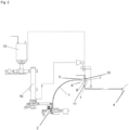
- FIG. 2 shows a system according to the invention with a pre-steamer 15, a digester 16 and a refiner 2, which is connected to the dryer 4 via a blow line 1, with a gluing device 3 being arranged between the dryer 4 and the refiner 2 is.
- the gluing device 3 is advantageously designed as a cyclone 6 and is designed with a cone 8 and an optional immersion tube 7 .
- the nozzle tube 10 is guided through the optional immersion tube 7, with at least one nozzle 11 being arranged at the end of the nozzle tube 10.
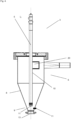
- the 3 shows a gluing device 3 according to the invention in detail, which is advantageously designed as a cyclone 6 .
- the cyclone 6 comprises an entry area 20, a cone 8, an exit area 13 designed as a cone exit area 9, and an optional immersion tube 7.
- the fibrous material-steam mixture is fed to the gluing device 3 in the circumferential direction through the entry area 20, as a result of which the fibrous material Steam mixture in the cyclone 6 forms a swirl flow around and along the axis 5 of the cyclone 6.
- a nozzle tube 10 is arranged inside the optional immersion tube 7, with the nozzle tube 10 being able to extend into the cone 8, preferably into the cone outlet region 9, and the glue being supplied to the at least one nozzle 11 through the nozzle tube 10.
- the nozzle 11 arranged in the interior of the swirl flow applies the glue to the fibrous material, with the glue flowing in the direction of the axis 5 and/or in the direction of the inner wall of the gluing device 3 and in particular from the inside radially outwards in the direction of the inner wall of the Cone 8 forming fiber ring is sprayed.
- the at least one nozzle 11 can alternatively or additionally also be arranged in the area of the wall of the cone 8 , preferably in the cone outlet area 9 . In this way, the glue can be applied to the fibrous material, with the glue then being injected from the outside inwards or radially inwards.
- the vapor of the fibrous material-vapour mixture which may contain pollutants, can be continuously discharged from the gluing device 3 through the optional immersion tube 7 and can be used in the system, in particular in the pre-steamer 15 and/or the boiler 16 .
- live steam is used as a propellant in a nozzle 11 designed, for example, as a two-component nozzle, and live steam is thus introduced into the cyclone 6, the fibrous material-steam mixture then fed to the dryer 4 having a lower pollutant load than the fibrous material-steam mixture fed to the cyclone 6.
- a helical scraper 14 for cleaning the inner wall of the cyclone 6 can be arranged in the cyclone 6 so as to be rotatable about the axis 5 .
- the cyclone 6 comprises an inlet area 20, a cone 8, an outlet area 13 configured as a cone outlet area 9.
- the fibrous material-steam mixture is fed to the gluing device 3 in the circumferential direction through the entry area 20, whereby the fibrous material-steam mixture then flows in the cyclone 6 forms a swirl flow around and along the axis 5 of the cyclone 6 .
- the nozzle tube 10 extends into the cone 8 , preferably into the cone outlet region 9 , and the glue is supplied to the at least one nozzle 11 through the nozzle tube 10 .
- the present invention offers numerous advantages over the prior art. It allows the glue to be distributed efficiently, with minimal use of chemicals or glue leading to an optimal result. In addition, according to the invention, there is only minimal contamination of the inner wall of the gluing device or cyclone by glue. The invention also allows a high thermal efficiency of the system, since steam can be discharged from the gluing device for further use. The gluing device according to the invention also allows any pollutant load present in the fibrous material-steam mixture to be reduced before it is introduced into the dryer. In addition, the swirl flow in the gluing device is set with a minimum pressure loss. Finally, the invention allows for an optimal arrangement of the nozzles, with the nozzles only being subjected to minimal abrasion by the fibrous material to be glued.
Landscapes
- Engineering & Computer Science (AREA)
- Life Sciences & Earth Sciences (AREA)
- Wood Science & Technology (AREA)
- Mechanical Engineering (AREA)
- Manufacturing & Machinery (AREA)
- Forests & Forestry (AREA)
- Chemical & Material Sciences (AREA)
- Chemical Kinetics & Catalysis (AREA)
- Paper (AREA)
- Dry Formation Of Fiberboard And The Like (AREA)
- Application Of Or Painting With Fluid Materials (AREA)
Applications Claiming Priority (2)
| Application Number | Priority Date | Filing Date | Title |
|---|---|---|---|
| ATA50828/2019A AT522983B1 (de) | 2019-09-30 | 2019-09-30 | Anlage und verfahren zur aufbringung von leim auf einen faserstoff |
| PCT/EP2020/068602 WO2021063555A1 (de) | 2019-09-30 | 2020-07-02 | Anlage und verfahren zur aufbringung von leim auf einen faserstoff |
Publications (3)
| Publication Number | Publication Date |
|---|---|
| EP4038233A1 EP4038233A1 (de) | 2022-08-10 |
| EP4038233B1 true EP4038233B1 (de) | 2023-08-30 |
| EP4038233C0 EP4038233C0 (de) | 2023-08-30 |
Family
ID=72046843
Family Applications (1)
| Application Number | Title | Priority Date | Filing Date |
|---|---|---|---|
| EP20754172.3A Active EP4038233B1 (de) | 2019-09-30 | 2020-07-02 | Anlage und verfahren zur aufbringung von leim auf einen faserstoff |
Country Status (5)
| Country | Link |
|---|---|
| EP (1) | EP4038233B1 (pl) |
| CN (1) | CN114514101B (pl) |
| AT (1) | AT522983B1 (pl) |
| PL (1) | PL4038233T3 (pl) |
| WO (1) | WO2021063555A1 (pl) |
Families Citing this family (1)
| Publication number | Priority date | Publication date | Assignee | Title |
|---|---|---|---|---|
| PL4122662T3 (pl) * | 2021-07-23 | 2024-07-15 | Fiberboard Gmbh | Sposób wytwarzania płyt pilśniowych o zmniejszonej emisji voc |
Family Cites Families (12)
| Publication number | Priority date | Publication date | Assignee | Title |
|---|---|---|---|---|
| JP2958572B2 (ja) * | 1990-10-12 | 1999-10-06 | 三井鉱山株式会社 | コーティング造粒装置 |
| SE508492C2 (sv) * | 1996-01-11 | 1998-10-12 | Sunds Defibrator Ind Ab | Anläggning för torkning och belimning av fibermateral |
| CN1308572A (zh) * | 1998-08-05 | 2001-08-15 | 弗劳恩霍弗应用技术研究院 | 制备中密度纤维板的方法 |
| DE10104047B4 (de) * | 2001-01-31 | 2005-12-01 | Johann Leonhartsberger | Vorrichtung zur Trockenbeleimung von Teilchen in Form von Fasern und Spänen |
| DE102006013567B4 (de) * | 2006-03-24 | 2013-09-26 | Glunz Ag | Verfahren und Vorrichtung zum Aufbringen von Bindemittel auf Partikel, insbesondere Fasern, die durch einen Blasgang gefördert werden |
| DE102006026124A1 (de) * | 2006-06-03 | 2007-12-06 | Glunz Ag | Verfahren und Vorrichtung zur Beleimung von Partikeln im Bereich eines Blasrohrs |
| DE102008052961B4 (de) * | 2008-10-23 | 2016-07-28 | SWISS KRONO Tec AG | Verfahren zum Herstellen von Holzwerkstoffen |
| PT2431144E (pt) * | 2010-09-15 | 2013-01-08 | Kronotec Ag | Método e dispositivo para a colagem húmida de fibras de madeira |
| CN102001121B (zh) * | 2010-10-20 | 2012-08-22 | 饶显生 | 树皮混合中密度纤维板的生产方法 |
| AT514329B1 (de) | 2013-08-01 | 2014-12-15 | Andritz Ag Maschf | Anlage und Verfahren zum Verarbeiten von Faserstoffen |
| ES2623824T3 (es) | 2014-05-02 | 2017-07-12 | SWISS KRONO Tec AG | Procedimiento e instalación para fabricar un panel de fibras de madera |
| WO2018215486A1 (de) * | 2017-05-22 | 2018-11-29 | Dieffenbacher GmbH Maschinen- und Anlagenbau | Beleimungseinrichtung zum beleimen von partikeln, vorrichtung einer oder für eine anlage zur herstellung von pressplatten, verfahren zur verhinderung von ablagerung von leim und/oder partikeln und verfahren zum beleimen von partikeln |
-
2019
- 2019-09-30 AT ATA50828/2019A patent/AT522983B1/de active
-
2020
- 2020-07-02 PL PL20754172.3T patent/PL4038233T3/pl unknown
- 2020-07-02 CN CN202080067789.6A patent/CN114514101B/zh active Active
- 2020-07-02 WO PCT/EP2020/068602 patent/WO2021063555A1/de not_active Ceased
- 2020-07-02 EP EP20754172.3A patent/EP4038233B1/de active Active
Also Published As
| Publication number | Publication date |
|---|---|
| EP4038233A1 (de) | 2022-08-10 |
| WO2021063555A1 (de) | 2021-04-08 |
| CN114514101B (zh) | 2023-03-28 |
| BR112022001634A2 (pt) | 2022-06-21 |
| EP4038233C0 (de) | 2023-08-30 |
| AT522983A1 (de) | 2021-04-15 |
| AT522983B1 (de) | 2022-12-15 |
| CN114514101A (zh) | 2022-05-17 |
| PL4038233T3 (pl) | 2024-03-04 |
Similar Documents
| Publication | Publication Date | Title |
|---|---|---|
| DE10153593B4 (de) | Vorrichtung und Verfahren zum Benetzen von Holzfasern mit einem Bindemittelfluid | |
| DE19740676C2 (de) | Verfahren zum Beleimen von Fasern | |
| US6409834B1 (en) | Gluing apparatus for wood fiber panel production plants | |
| EP2431144B1 (de) | Verfahren und Einrichtung zur Nassbeleimung von Holzfasern | |
| WO2015056174A2 (en) | Process and device for gluing fibers for the production of fiberboards | |
| AT522983B1 (de) | Anlage und verfahren zur aufbringung von leim auf einen faserstoff | |
| DE3143895C2 (de) | Verfahren und Vorrichtung zum Beleimen von teilchenförmigem Gut in Form von Spänen, Fasern o.dgl. | |
| EP3027806B1 (de) | Anlage und verfahren zum verarbeiten von faserstoffen | |
| CA2176616A1 (en) | Gluing machine for wood fibreboard panel, production plants, and a plant using the gluing machine | |
| WO2000007785A1 (de) | Verfahren zur herstellung von mdf-platten | |
| EP1337384B1 (de) | Anlage zur faseraufbereitung | |
| EP1670623B1 (de) | Verfahren zur herstellung von faserplatten aus holzfasern | |
| DE10104047B4 (de) | Vorrichtung zur Trockenbeleimung von Teilchen in Form von Fasern und Spänen | |
| AT527210B1 (de) | Anlage und verfahren zur herstellung einer faserplatte | |
| BR112022001634B1 (pt) | Método para aplicação de cola em um material fibroso e instalação para processar materiais fibrosos com um refinador | |
| DE3043730A1 (de) | Zentrifugalstromtrockner | |
| DE1442501A1 (de) | Verfahren zum Ausscheiden von Fremdkoerpern aus einem fliessfaehigen Medium mittels eines Zyklons und Zyklon zur Ausuebung des Verfahrens | |
| DE102006024895A1 (de) | Verfahren und Vorrichtung zum Beleimen von Fasern | |
| WO2025114464A1 (en) | A system for mixing lignocellulosic fibers and a binding agent to be pressed into a fiberboard | |
| EP2179826B1 (de) | Anlage zum Herstellen von Holzwerkstoffen | |
| WO2026059511A2 (en) | A nozzle | |
| AT395735B (de) | Vorrichtung zur herstellung von refinerstoff aus lignozellulosematerial | |
| DE202015102402U1 (de) | Vorrichtung zum Beleimen von Fasern oder faserähnlichem Material | |
| DE102015107318A1 (de) | Verfahren und Vorrichtung zum Beleimen von Fasern oder faserähnlichem Material | |
| DE2057594A1 (de) | Verfahren und Vorrichtung zum kontinuierlichen Mischen von Stoffen mit Zusatzkomponenten |
Legal Events
| Date | Code | Title | Description |
|---|---|---|---|
| STAA | Information on the status of an ep patent application or granted ep patent |
Free format text: STATUS: UNKNOWN |
|
| STAA | Information on the status of an ep patent application or granted ep patent |
Free format text: STATUS: THE INTERNATIONAL PUBLICATION HAS BEEN MADE |
|
| PUAI | Public reference made under article 153(3) epc to a published international application that has entered the european phase |
Free format text: ORIGINAL CODE: 0009012 |
|
| STAA | Information on the status of an ep patent application or granted ep patent |
Free format text: STATUS: REQUEST FOR EXAMINATION WAS MADE |
|
| 17P | Request for examination filed |
Effective date: 20220128 |
|
| AK | Designated contracting states |
Kind code of ref document: A1 Designated state(s): AL AT BE BG CH CY CZ DE DK EE ES FI FR GB GR HR HU IE IS IT LI LT LU LV MC MK MT NL NO PL PT RO RS SE SI SK SM TR |
|
| DAV | Request for validation of the european patent (deleted) | ||
| DAX | Request for extension of the european patent (deleted) | ||
| REG | Reference to a national code |
Ref country code: DE Ref legal event code: R079 Free format text: PREVIOUS MAIN CLASS: D21B0001020000 Ipc: B01F0025721000 Ref document number: 502020005019 Country of ref document: DE |
|
| GRAP | Despatch of communication of intention to grant a patent |
Free format text: ORIGINAL CODE: EPIDOSNIGR1 |
|
| STAA | Information on the status of an ep patent application or granted ep patent |
Free format text: STATUS: GRANT OF PATENT IS INTENDED |
|
| INTG | Intention to grant announced |
Effective date: 20230224 |
|
| RIC1 | Information provided on ipc code assigned before grant |
Ipc: D21B 1/06 20060101ALI20230213BHEP Ipc: B27N 1/02 20060101ALI20230213BHEP Ipc: D21B 1/02 20060101ALI20230213BHEP Ipc: B08B 9/08 20060101ALI20230213BHEP Ipc: B08B 9/00 20060101ALI20230213BHEP Ipc: B04C 9/00 20060101ALI20230213BHEP Ipc: B04C 5/22 20060101ALI20230213BHEP Ipc: B01F 25/721 20220101AFI20230213BHEP |
|
| GRAS | Grant fee paid |
Free format text: ORIGINAL CODE: EPIDOSNIGR3 |
|
| GRAA | (expected) grant |
Free format text: ORIGINAL CODE: 0009210 |
|
| STAA | Information on the status of an ep patent application or granted ep patent |
Free format text: STATUS: THE PATENT HAS BEEN GRANTED |
|
| AK | Designated contracting states |
Kind code of ref document: B1 Designated state(s): AL AT BE BG CH CY CZ DE DK EE ES FI FR GB GR HR HU IE IS IT LI LT LU LV MC MK MT NL NO PL PT RO RS SE SI SK SM TR |
|
| REG | Reference to a national code |
Ref country code: GB Ref legal event code: FG4D Free format text: NOT ENGLISH |
|
| REG | Reference to a national code |
Ref country code: CH Ref legal event code: EP |
|
| REG | Reference to a national code |
Ref country code: DE Ref legal event code: R096 Ref document number: 502020005019 Country of ref document: DE |
|
| REG | Reference to a national code |
Ref country code: IE Ref legal event code: FG4D Free format text: LANGUAGE OF EP DOCUMENT: GERMAN |
|
| U01 | Request for unitary effect filed |
Effective date: 20230830 |
|
| U07 | Unitary effect registered |
Designated state(s): AT BE BG DE DK EE FI FR IT LT LU LV MT NL PT SE SI Effective date: 20230905 |
|
| PG25 | Lapsed in a contracting state [announced via postgrant information from national office to epo] |
Ref country code: GR Free format text: LAPSE BECAUSE OF FAILURE TO SUBMIT A TRANSLATION OF THE DESCRIPTION OR TO PAY THE FEE WITHIN THE PRESCRIBED TIME-LIMIT Effective date: 20231201 |
|
| PG25 | Lapsed in a contracting state [announced via postgrant information from national office to epo] |
Ref country code: IS Free format text: LAPSE BECAUSE OF FAILURE TO SUBMIT A TRANSLATION OF THE DESCRIPTION OR TO PAY THE FEE WITHIN THE PRESCRIBED TIME-LIMIT Effective date: 20231230 |
|
| PG25 | Lapsed in a contracting state [announced via postgrant information from national office to epo] |
Ref country code: RS Free format text: LAPSE BECAUSE OF FAILURE TO SUBMIT A TRANSLATION OF THE DESCRIPTION OR TO PAY THE FEE WITHIN THE PRESCRIBED TIME-LIMIT Effective date: 20230830 Ref country code: NO Free format text: LAPSE BECAUSE OF FAILURE TO SUBMIT A TRANSLATION OF THE DESCRIPTION OR TO PAY THE FEE WITHIN THE PRESCRIBED TIME-LIMIT Effective date: 20231130 Ref country code: IS Free format text: LAPSE BECAUSE OF FAILURE TO SUBMIT A TRANSLATION OF THE DESCRIPTION OR TO PAY THE FEE WITHIN THE PRESCRIBED TIME-LIMIT Effective date: 20231230 Ref country code: HR Free format text: LAPSE BECAUSE OF FAILURE TO SUBMIT A TRANSLATION OF THE DESCRIPTION OR TO PAY THE FEE WITHIN THE PRESCRIBED TIME-LIMIT Effective date: 20230830 Ref country code: GR Free format text: LAPSE BECAUSE OF FAILURE TO SUBMIT A TRANSLATION OF THE DESCRIPTION OR TO PAY THE FEE WITHIN THE PRESCRIBED TIME-LIMIT Effective date: 20231201 |
|
| PG25 | Lapsed in a contracting state [announced via postgrant information from national office to epo] |
Ref country code: ES Free format text: LAPSE BECAUSE OF FAILURE TO SUBMIT A TRANSLATION OF THE DESCRIPTION OR TO PAY THE FEE WITHIN THE PRESCRIBED TIME-LIMIT Effective date: 20230830 |
|
| PG25 | Lapsed in a contracting state [announced via postgrant information from national office to epo] |
Ref country code: SM Free format text: LAPSE BECAUSE OF FAILURE TO SUBMIT A TRANSLATION OF THE DESCRIPTION OR TO PAY THE FEE WITHIN THE PRESCRIBED TIME-LIMIT Effective date: 20230830 Ref country code: RO Free format text: LAPSE BECAUSE OF FAILURE TO SUBMIT A TRANSLATION OF THE DESCRIPTION OR TO PAY THE FEE WITHIN THE PRESCRIBED TIME-LIMIT Effective date: 20230830 Ref country code: ES Free format text: LAPSE BECAUSE OF FAILURE TO SUBMIT A TRANSLATION OF THE DESCRIPTION OR TO PAY THE FEE WITHIN THE PRESCRIBED TIME-LIMIT Effective date: 20230830 Ref country code: CZ Free format text: LAPSE BECAUSE OF FAILURE TO SUBMIT A TRANSLATION OF THE DESCRIPTION OR TO PAY THE FEE WITHIN THE PRESCRIBED TIME-LIMIT Effective date: 20230830 Ref country code: SK Free format text: LAPSE BECAUSE OF FAILURE TO SUBMIT A TRANSLATION OF THE DESCRIPTION OR TO PAY THE FEE WITHIN THE PRESCRIBED TIME-LIMIT Effective date: 20230830 |
|
| REG | Reference to a national code |
Ref country code: DE Ref legal event code: R097 Ref document number: 502020005019 Country of ref document: DE |
|
| PLBE | No opposition filed within time limit |
Free format text: ORIGINAL CODE: 0009261 |
|
| STAA | Information on the status of an ep patent application or granted ep patent |
Free format text: STATUS: NO OPPOSITION FILED WITHIN TIME LIMIT |
|
| 26N | No opposition filed |
Effective date: 20240603 |
|
| U20 | Renewal fee for the european patent with unitary effect paid |
Year of fee payment: 5 Effective date: 20240724 |
|
| PG25 | Lapsed in a contracting state [announced via postgrant information from national office to epo] |
Ref country code: MC Free format text: LAPSE BECAUSE OF FAILURE TO SUBMIT A TRANSLATION OF THE DESCRIPTION OR TO PAY THE FEE WITHIN THE PRESCRIBED TIME-LIMIT Effective date: 20230830 |
|
| REG | Reference to a national code |
Ref country code: CH Ref legal event code: PL |
|
| GBPC | Gb: european patent ceased through non-payment of renewal fee |
Effective date: 20240702 |
|
| PG25 | Lapsed in a contracting state [announced via postgrant information from national office to epo] |
Ref country code: CH Free format text: LAPSE BECAUSE OF NON-PAYMENT OF DUE FEES Effective date: 20240731 |
|
| PG25 | Lapsed in a contracting state [announced via postgrant information from national office to epo] |
Ref country code: GB Free format text: LAPSE BECAUSE OF NON-PAYMENT OF DUE FEES Effective date: 20240702 |
|
| PGFP | Annual fee paid to national office [announced via postgrant information from national office to epo] |
Ref country code: PL Payment date: 20250624 Year of fee payment: 6 |
|
| PGFP | Annual fee paid to national office [announced via postgrant information from national office to epo] |
Ref country code: TR Payment date: 20250624 Year of fee payment: 6 |
|
| PG25 | Lapsed in a contracting state [announced via postgrant information from national office to epo] |
Ref country code: IE Free format text: LAPSE BECAUSE OF NON-PAYMENT OF DUE FEES Effective date: 20240702 |
|
| U20 | Renewal fee for the european patent with unitary effect paid |
Year of fee payment: 6 Effective date: 20250728 |
|
| PG25 | Lapsed in a contracting state [announced via postgrant information from national office to epo] |
Ref country code: CY Free format text: LAPSE BECAUSE OF FAILURE TO SUBMIT A TRANSLATION OF THE DESCRIPTION OR TO PAY THE FEE WITHIN THE PRESCRIBED TIME-LIMIT; INVALID AB INITIO Effective date: 20200702 |
|
| PG25 | Lapsed in a contracting state [announced via postgrant information from national office to epo] |
Ref country code: HU Free format text: LAPSE BECAUSE OF FAILURE TO SUBMIT A TRANSLATION OF THE DESCRIPTION OR TO PAY THE FEE WITHIN THE PRESCRIBED TIME-LIMIT; INVALID AB INITIO Effective date: 20200702 |