EP4037560B1 - Nicht-invasive bestimmung von glukose - Google Patents
Nicht-invasive bestimmung von glukose Download PDFInfo
- Publication number
- EP4037560B1 EP4037560B1 EP20771873.5A EP20771873A EP4037560B1 EP 4037560 B1 EP4037560 B1 EP 4037560B1 EP 20771873 A EP20771873 A EP 20771873A EP 4037560 B1 EP4037560 B1 EP 4037560B1
- Authority
- EP
- European Patent Office
- Prior art keywords
- radiation
- terahertz
- unit
- wavelength
- region
- Prior art date
- Legal status (The legal status is an assumption and is not a legal conclusion. Google has not performed a legal analysis and makes no representation as to the accuracy of the status listed.)
- Active
Links
Images





Classifications
-
- A—HUMAN NECESSITIES
- A61—MEDICAL OR VETERINARY SCIENCE; HYGIENE
- A61B—DIAGNOSIS; SURGERY; IDENTIFICATION
- A61B5/00—Measuring for diagnostic purposes; Identification of persons
- A61B5/145—Measuring characteristics of blood in vivo, e.g. gas concentration or pH-value ; Measuring characteristics of body fluids or tissues, e.g. interstitial fluid or cerebral tissue
- A61B5/14532—Measuring characteristics of blood in vivo, e.g. gas concentration or pH-value ; Measuring characteristics of body fluids or tissues, e.g. interstitial fluid or cerebral tissue for measuring glucose, e.g. by tissue impedance measurement
-
- A—HUMAN NECESSITIES
- A61—MEDICAL OR VETERINARY SCIENCE; HYGIENE
- A61B—DIAGNOSIS; SURGERY; IDENTIFICATION
- A61B5/00—Measuring for diagnostic purposes; Identification of persons
- A61B5/01—Measuring temperature of body parts ; Diagnostic temperature sensing, e.g. for malignant or inflamed tissue
- A61B5/015—By temperature mapping of body part
-
- A—HUMAN NECESSITIES
- A61—MEDICAL OR VETERINARY SCIENCE; HYGIENE
- A61B—DIAGNOSIS; SURGERY; IDENTIFICATION
- A61B5/00—Measuring for diagnostic purposes; Identification of persons
- A61B5/05—Detecting, measuring or recording for diagnosis by means of electric currents or magnetic fields; Measuring using microwaves or radio waves
- A61B5/0507—Detecting, measuring or recording for diagnosis by means of electric currents or magnetic fields; Measuring using microwaves or radio waves using microwaves or terahertz waves
-
- A—HUMAN NECESSITIES
- A61—MEDICAL OR VETERINARY SCIENCE; HYGIENE
- A61B—DIAGNOSIS; SURGERY; IDENTIFICATION
- A61B5/00—Measuring for diagnostic purposes; Identification of persons
- A61B5/145—Measuring characteristics of blood in vivo, e.g. gas concentration or pH-value ; Measuring characteristics of body fluids or tissues, e.g. interstitial fluid or cerebral tissue
- A61B5/1455—Measuring characteristics of blood in vivo, e.g. gas concentration or pH-value ; Measuring characteristics of body fluids or tissues, e.g. interstitial fluid or cerebral tissue using optical sensors, e.g. spectral photometrical oximeters
-
- A—HUMAN NECESSITIES
- A61—MEDICAL OR VETERINARY SCIENCE; HYGIENE
- A61B—DIAGNOSIS; SURGERY; IDENTIFICATION
- A61B5/00—Measuring for diagnostic purposes; Identification of persons
- A61B5/68—Arrangements of detecting, measuring or recording means, e.g. sensors, in relation to patient
- A61B5/6801—Arrangements of detecting, measuring or recording means, e.g. sensors, in relation to patient specially adapted to be attached to or worn on the body surface
- A61B5/6813—Specially adapted to be attached to a specific body part
- A61B5/6825—Hand
- A61B5/6826—Finger
-
- A—HUMAN NECESSITIES
- A61—MEDICAL OR VETERINARY SCIENCE; HYGIENE
- A61B—DIAGNOSIS; SURGERY; IDENTIFICATION
- A61B5/00—Measuring for diagnostic purposes; Identification of persons
- A61B5/68—Arrangements of detecting, measuring or recording means, e.g. sensors, in relation to patient
- A61B5/6801—Arrangements of detecting, measuring or recording means, e.g. sensors, in relation to patient specially adapted to be attached to or worn on the body surface
- A61B5/6843—Monitoring or controlling sensor contact pressure
-
- G—PHYSICS
- G01—MEASURING; TESTING
- G01N—INVESTIGATING OR ANALYSING MATERIALS BY DETERMINING THEIR CHEMICAL OR PHYSICAL PROPERTIES
- G01N21/00—Investigating or analysing materials by the use of optical means, i.e. using sub-millimetre waves, infrared, visible or ultraviolet light
- G01N21/17—Systems in which incident light is modified in accordance with the properties of the material investigated
- G01N21/25—Colour; Spectral properties, i.e. comparison of effect of material on the light at two or more different wavelengths or wavelength bands
- G01N21/31—Investigating relative effect of material at wavelengths characteristic of specific elements or molecules, e.g. atomic absorption spectrometry
- G01N21/35—Investigating relative effect of material at wavelengths characteristic of specific elements or molecules, e.g. atomic absorption spectrometry using infrared light
- G01N21/3581—Investigating relative effect of material at wavelengths characteristic of specific elements or molecules, e.g. atomic absorption spectrometry using infrared light using far infrared light; using Terahertz radiation
-
- G—PHYSICS
- G01—MEASURING; TESTING
- G01N—INVESTIGATING OR ANALYSING MATERIALS BY DETERMINING THEIR CHEMICAL OR PHYSICAL PROPERTIES
- G01N33/00—Investigating or analysing materials by specific methods not covered by groups G01N1/00 - G01N31/00
- G01N33/48—Biological material, e.g. blood, urine; Haemocytometers
- G01N33/483—Physical analysis of biological material
- G01N33/487—Physical analysis of biological material of liquid biological material
- G01N33/49—Blood
Definitions
- the present invention relates to the non-invasive determination of glucose in blood by detecting and evaluating radiation from the terahertz range and the IR range, in particular the non-invasive determination of glucose in capillary blood.
- WO 2014/0206549 describes a device for measuring raw data For the non-invasive determination of a blood parameter, such as glucose concentration, infrared (IR) radiation from an external radiation source is coupled into the patient's body surface at multiple measuring points, and the IR radiation generated in the body surface is detected by a sensor device at multiple measuring points.
- IR infrared
- WO 2018/122 relates to a device and a method for the non-invasive quantitative determination of an analyte in blood, in particular for the non-invasive quantitative determination of glucose in capillary blood.
- a selected body area is irradiated with IR radiation in the region of preferably 8-12 ⁇ m. Subsequently, a selective evaluation of the reflected IR radiation from near-surface blood vessels of the irradiated body area is performed.
- WO 2019/034722 also relates to a device and a method for the non-invasive quantitative determination of an analyte in blood, in particular for the non-invasive quantitative determination of glucose in capillary blood.
- the IR radiation emitted by the body is evaluated, preferably in a wavelength range of 8-12 ⁇ m, without the use of external radiation sources.
- Another device for determining glucose is from the US 2016/080665 known.
- the present invention provides a method for the non-invasive determination of glucose in a body fluid and the use of a device in this method, with which the disadvantages of the prior art can be at least partially avoided.
- the invention is based on the discovery that a simple, rapid, and sufficiently accurate quantitative determination of glucose in the blood of a test subject is possible using non-invasive methods.
- the present invention is based on the detection of radiation from the body region of a test subject to be examined in two different wavelength ranges and the combined evaluation of the resulting measurement signals. This involves irradiating a predetermined body region of the test subject, e.g., a fingertip, with terahertz radiation, and detecting the reflected terahertz radiation in a terahertz wavelength range in which the intensity of the reflected terahertz radiation changes depending on the glucose concentration.
- endogenous IR radiation originating from a predetermined body region of the test subject is separately detected at at least two different wavelengths or wavelength ranges in the wavelength range from approximately 8 ⁇ m to approximately 12 ⁇ m. Detection occurs at a first wavelength or a first wavelength range, where the intensity of the reflected IR radiation is essentially independent of the glucose concentration, and independently of this at a second wavelength or a second wavelength range, where the intensity of the reflected IR radiation changes depending on the glucose concentration.
- the glucose concentration can be determined by differential evaluation of the measurement signals from both IR wavelengths or IR wavelength ranges in combination with an evaluation of the measurement signals in the terahertz range.
- a non-invasive Determining glucose in blood through combined detection and analysis of radiation from two different spectral ranges improves the accuracy of analyte determination and reduces the susceptibility to errors.
- this method can reduce the influence of interfering substances, since such interfering substances typically exhibit absorption behavior that interferes with glucose only in one of the two spectral ranges.
- suitable algorithms it is possible to quantitatively determine the contribution of the respective interfering substance to the measurement signal, allowing for precise correction.
- the contribution of an interfering substance in the IR measurement signal is quantitatively determined by the combined determination in the terahertz and IR ranges by evaluating the terahertz signal, whereby a corrected IR measurement signal is obtained from which the contribution of the interfering substance is at least largely or completely eliminated.
- the contribution of an interfering substance in the terahertz measurement signal is quantitatively determined by the combined determination in the terahertz and IR ranges by evaluating the IR signal, whereby a corrected terahertz measurement signal is obtained from which the contribution of the interfering substance is at least largely or completely eliminated.
- the combined determination in the terahertz and IR range quantitatively determines the contribution of a first interfering substance in the terahertz measurement signal by evaluating the IR signal and the contribution of a second interfering substance in the IR measurement signal by evaluating the terahertz signal, whereby corrected terahertz and IR measurement signals are obtained from which the contributions of the first and second interfering substances are at least largely or completely eliminated.
- terahertz range in the context of the present invention, unless otherwise stated, refers to a frequency range from about 60 gigahertz (GHz) to about 3 terahertz (THz), corresponding to a wavelength range or region of about 5 mm to about 0.1 mm, or a subrange thereof.
- the frequency range may extend from about 0.3 THz to about 3 THz (corresponding to a wavelength range or region of about 1 mm to about 0.1 mm) or from about 60 GHz to about 2.5 THz (corresponding to a wavelength range or region of about 5 mm to about 0.12 mm).
- IR range in the context of the present invention refers, unless otherwise stated, to a wavelength range or region from about 1 ⁇ m to about 20 ⁇ m, or a subrange thereof.
- the wavelength range or region can range from about 5 ⁇ m to about 15 ⁇ m, and in particular from about 8 ⁇ m to about 12 ⁇ m.
- the temperature of the body area to be examined e.g. a fingertip
- the temperature of the sensors used to detect terahertz radiation and IR radiation are also measured, whereby the temperature of the sensors is set to a value which is lower than the temperature of the body region to be examined.
- the temperature of the sensors is set to a predetermined value, e.g. in the range from 10 °C to 25 °C, e.g. by embedding them in a metal block whose temperature is regulated by a temperature setting element, e.g. a Peltier element, and determined precisely with a temperature measuring element, e.g. with a precision of maximum ⁇ 0.1 °C or maximum ⁇ 0.01 °C.
- the temperature of the body region to be examined can - depending on the test subject and the external conditions - assume a variable value, which is determined according to the invention precisely with a temperature measuring element, e.g. with a precision of maximum ⁇ 0.1 °C or maximum ⁇ 0.01 °C.
- the evaluation of the measurement signal includes temperature compensation of the obtained measurement signals, taking into account the temperature value of the body region to be examined and the temperature value of the sensor unit, and in particular the resulting temperature difference. Consequently, the present invention relates to the non-invasive determination of glucose by jointly evaluating terahertz radiation and the body's own IR radiation with temperature compensation.
- a selective evaluation of endogenous IR radiation in the region of approximately 8 ⁇ m to approximately 12 ⁇ m from near-surface blood vessels of the examined body region can be carried out, in particular a selective evaluation of endogenous IR radiation from the capillary blood vessels of the dermis.
- endogenous IR radiation is composed of several components that can be analyzed separately.
- the component of the endogenous IR radiation originating from near-surface blood vessels exhibits a temporal variation dependent on the arterial pulse rate of the test subject. Due to this variation, a Discrimination between signals that change with the pulse rate and signals that are independent of the pulse rate can be carried out during the evaluation.
- the present invention allows an accurate and reproducible determination of glucose in blood, e.g. with an accuracy of ⁇ 2.5% compared to a reference measurement using an X-ray diffractometer.
- a first aspect of the present invention thus relates to the use of a device for the non-invasive determination of glucose in the blood of a test subject, as defined in claim 1.
- the device contains a radiation source (b) for generating Terahertz radiation, in particular terahertz radiation in a wavelength range from approximately 0.1 mm to approximately 5 mm, from approximately 0.12 mm to approximately 5 mm, or from approximately 0.1 mm to approximately 1 mm, for irradiating the body region to be examined. After irradiation of the body region to be examined, which has been introduced into the recording unit (a), the terahertz radiation is reflected.
- the device further includes a unit (c) (ii) for detecting terahertz radiation.
- the device does not necessarily contain an external IR radiation source, as it is designed to detect and evaluate the body's own IR radiation. Preferably, no external IR radiation source is present.
- the body's own IR radiation is emitted by the body region to be examined, which is introduced into the recording unit (a).
- the device contains a unit (c) (ii) for detecting the body's own IR radiation.
- the temperature, in particular the core temperature, of the body region to be examined, which is introduced into the recording unit, is precisely determined by a temperature measuring element (d) (i), e.g., a temperature sensor.
- a temperature measuring element (d) (i) e.g., a temperature sensor.
- an element (d) (ii) for adjusting the body temperature of the body region to be examined can be provided in the recording unit (a), i.e., a heating and/or cooling element, e.g., a Peltier element.
- the device further comprises means (e) (i) for determining the temperature in the unit for detecting reflected terahertz radiation (c) (i) and/or the unit for detecting endogenous IR radiation (c) (ii), e.g. a temperature sensor, and means (e) (ii) for maintaining the temperature in the unit for detecting reflected terahertz radiation (c) (i) and/or the unit for detecting endogenous IR radiation (c) (ii) at a substantially equal and preferably constant temperature level.
- the element (e) (ii) is for the precise Adjustment of the temperature of the radiation detection unit (c) (i) and/or (c) (ii) to a value lower than the body temperature is provided.
- the element (e) (ii) comprises a body made of thermally conductive material, e.g., a metal block, and means for supplying and/or dissipating heat, e.g., a heating and/or cooling element, such as a Peltier element.
- a heating and/or cooling element such as a Peltier element.
- the device is intended for recording a body region of a test subject, in particular for recording a body region of a human test subject, e.g., a fingertip, an earlobe, or a heel, or parts thereof, in order to determine the endogenous IR radiation emitted therefrom.
- a body region to be examined is a fingertip.
- the device contains a unit (a) for receiving the body region to be irradiated, which may, for example, comprise a support element for the relevant body region, e.g., the fingertip.
- a support element for the relevant body region e.g., the fingertip.
- the shape of the support element is adapted to the body region on which the determination is being performed.
- a substantially planar support element may be provided.
- the support element (a) is partially thermally insulated from the radiation detection unit (c) (i) and/or (c) (ii), e.g. by being formed at least partially from thermally insulating material, e.g. a plastic such as a polyurethane foam.
- the support element contains one or more regions that are transparent to terahertz radiation in the region of preferably about 0.1 mm to about 5 mm or from about 0.1 mm to about 1 mm and to IR radiation in the region of preferably about 8 ⁇ m to about 12 ⁇ m, in order to enable unhindered penetration of the terahertz and IR radiation emitted by the body region to be examined.
- the transparent region of the support element can, for example, have an area of about 0.5 cm2 to approximately 1.5 cm2 and be circular, for example.
- suitable materials in the transparent region of the support element are silicon, germanium, or organic terahertz- and IR-transparent polymers.
- the support element can be formed in any suitable shape, for example, as a disc.
- an element (d) (i) for measuring the temperature in the body region to be examined comprises a temperature sensor, e.g., a bolometer or thermopile.
- a temperature adjustment element (d) (ii) can be provided, e.g., a heating and/or cooling element, in particular a Peltier element, to enable precise adjustment of the temperature of the body region to be examined, e.g., with a precision of a maximum of ⁇ 0.1 °C or a maximum of ⁇ 0.01 °C.
- the temperature adjustment element can be configured to set a temperature of the body region of 25 °C or more, e.g., approximately 28-38 °C.
- an element for measuring the pigmentation of the body region to be determined (d) (iii) e.g., a colorimetric sensor, can be provided.
- the support element preferably comprises means, e.g., sensors, for detecting and/or monitoring the support position and/or the support pressure for the body region to be examined.
- the support position and/or the support pressure can be detected individually for each body region and adapted if necessary.
- the individual adaptation can, for example, comprise a one-time or repeated comparison of the measurement signal originating from the non-invasive device with a reference signal obtained conventionally, e.g., via an invasive determination using a conventional test strip or a sensor inserted into the body. This comparison can be performed during the initial use of the device and, if necessary, at intervals, e.g., daily, every other day, weekly, etc. repeated.
- the calibration comprises an adjustment of the support position and/or support pressure for the body region to be examined in order to obtain a stable, reproducible measurement signal that corresponds as closely as possible to the reference signal.
- the device can contain sensors for detecting and/or monitoring the support position of the body region to be irradiated, e.g. with regard to the x, y and z coordinates with respect to the support element, and/or for detecting and/or monitoring the support pressure, e.g. in a range of approximately 0.5-100 N, preferably in the range of approximately 10-50 N and particularly preferably approximately 20 N.
- a sensor for detecting and/or monitoring the support pressure can, for example, contain a load cell.
- a sensor for detecting and/or monitoring the support position can contain a camera, e.g. a CCD camera and/or a pulse sensor.
- the settings for support position and/or support pressure determined through adaptation are preferably registered and stored by the device. During subsequent use of the device, the correct support position or support pressure can then be indicated by a signal, e.g., a visual and/or acoustic signal. Glucose measurement will only start once the specified correct settings have been verified.
- the device contains a radiation source (b) for generating terahertz radiation.
- This radiation source can be designed to generate coherent terahertz radiation.
- terahertz radiation can be generated by frequency multiplication or difference frequency formation of several laser signals, e.g., distributed feedback lasers, quantum cascade lasers, molecular gas lasers, free-electron lasers, optical parametric oscillators, and backward wave oscillators.
- photodiodes can be used, which convert the difference frequency of two lasers into alternating current, which is emitted by a suitable photoconductive antenna in the form of terahertz radiation.
- terahertz radiation can be converted into terahertz radiation by a pulsed laser, e.g., with a wavelength in the range of 500-2,000 nm, e.g., 800 nm, using a suitable terahertz antenna.
- the power of such a laser is typically about 1 mW to about 1 W.
- a terahertz transmit/receive chip can also be used.
- a transmit/receive chip can be made of silicon- and/or germanium-based materials.
- the chip contains one or more amplifiers, e.g., low-noise amplifiers (LNAs), one or more quadrature mixers, one or more polyphase filters, one or more frequency dividers, and/or an oscillator with at least one tuning input for generating terahertz radiation.
- LNAs low-noise amplifiers
- quadrature mixers e.g., one or more quadrature mixers
- polyphase filters e.g., one or more polyphase filters
- frequency dividers e.g., one or more frequency dividers
- an oscillator with at least one tuning input for generating terahertz radiation.
- several, e.g., 2, 3, or 4 tuning inputs are present to vary the bandwidth of the terahertz radiation as needed.
- the power of such a chip can range from approximately 0.01 mW to approximately 100 mW, in particular from approximately 0.1 mW to approximately 1 mW.
- the chip may have a power of approximately 1 mW.
- the size of such a chip may be in the range of up to approximately 100 mm 2 , advantageously approximately 10 mm 2 to approximately 50 mm 2 , for example, approximately 25 mm 2 .
- Such terahertz chips are available, for example, from Silicon Radar GmbH.
- a terahertz antenna is present, e.g. a patch antenna or a dipole antenna.
- the effective power of the terahertz radiation source ie the power radiated onto the body area to be examined, is preferably about 1 mW to about 100 mW, with the radiation being continuous or pulsed. can be submitted.
- the device contains a unit (c) for detecting radiation, namely a unit for detecting terahertz radiation (c) (i) and a unit for detecting IR radiation (c) (ii).
- the detection unit (c) (i) for detecting terahertz radiation contains one or more sensors or detectors which are provided for detecting terahertz radiation, in particular terahertz radiation in the frequency range from approximately 60 gigahertz (GHz) to approximately 3 terahertz (THz) corresponding to a wavelength range or a wavelength region of approximately 0.1 mm to approximately 5 mm or in a sub-range thereof, e.g. in the range from approximately 0.12 mm to approximately 5 mm, from approximately 0.1 mm to approximately 1 mm or in a sub-range thereof.
- GHz gigahertz
- THz terahertz
- At least one focusing lens is present in the beam path between the terahertz radiation source and the body region to be examined and/or in the beam path between the body region to be examined and the terahertz detection unit (c) (i), e.g., a spherical lens, an aspherical lens, or a Fresnel lens made of a material that is essentially transparent to terahertz radiation, such as polypropylene or HD polyethylene.
- the lens serves to focus the terahertz radiation radiated into the body region to be examined from the terahertz radiation source to a predetermined penetration depth into the body region, e.g., of approximately 3-4 mm, and/or to focus the terahertz radiation reflected from the body region to be examined onto the terahertz detection unit.
- the terahertz radiation reflected from the body can be amplified in one or more steps before being directed to the detection unit (c) (i).
- the amplification takes place in a first step by an LNA.
- the reflected terahertz radiation can then be directed to a mixer and mixed (multiplied) with the transmitted signal.
- the mixing result can then be further amplified.
- amplification can occur by a factor of 10 3 or higher, 10 4 or higher, and up to 10 6 or 10 7 .
- the signal can be amplified in several steps, e.g., in two steps, with each step providing a signal amplification by a factor of 10 2 to 10 3 .
- the unit for detecting terahertz radiation is configured to detect terahertz radiation in a wavelength range in which the intensity of the reflected terahertz radiation changes depending on the glucose concentration.
- the unit (c) (i) is configured to detect a broadband spectrum in the terahertz range, in particular comprising a frequency range from approximately 60 gigahertz (GHz) to approximately 3 terahertz (THz) corresponding to a wavelength range or a wavelength region of approximately 0.1 mm to approximately 5 mm, e.g., a wavelength range from approximately 0.1 mm to approximately 0.25 mm (corresponding to a wavenumber range of approximately 100 cm -1 to approximately 40 cm -1 or in a subrange thereof).
- GHz gigahertz
- THz terahertz
- the result of the terahertz measurement can be displayed separately or combined with the result of the IR measurement on a display.
- the device contains a unit (c) (ii) for detecting endogenous IR radiation from the examined body region, which is configured for the separate detection of IR radiation at at least two different wavelengths or wavelength ranges, preferably in the region of approximately 8 ⁇ m to approximately 12 ⁇ m.
- this unit is configured for the separate detection of IR radiation at at least two different wavelengths or wavelength ranges in the region of approximately 8-10 ⁇ m.
- a third IR sensor without a filter can be used for comparison measurements as a reference temperature.
- the detection unit (c) (ii) for detecting IR radiation contains one or more sensors designed to detect IR radiation.
- the detection unit (c) (ii) contains a plurality of sensors designed for the separate detection of IR radiation with at least two different wavelengths or wavelength ranges.
- the device may in turn contain a sensor designed for the time-dependent, separate detection of IR radiation with at least two different wavelengths or wavelength ranges.
- the detection unit (c) (ii) is configured for the separate detection of IR radiation at at least a first wavelength or a first wavelength range and at at least a second wavelength or at least a second wavelength range.
- the first wavelength or the first wavelength range preferably lies in the region of an absorption minimum for glucose.
- the second wavelength or the second wavelength range preferably lies in the region of an absorption band of glucose, i.e., in a region in which glucose exhibits strong absorption, preferably an absorption maximum.
- the device contains at least one first sensor and at least one second sensor, each configured to separately detect IR radiation with different wavelengths or wavelength ranges in the region of approximately 8-12 ⁇ m.
- a first sensor is selected such that it is configured to detect IR radiation with a first wavelength or with a first wavelength range where the intensity of the body's own IR radiation is essentially independent of the glucose concentration.
- a second sensor is selected to detect IR radiation with a second wavelength or wavelength range, where the intensity of the body's own IR radiation changes depending on the glucose concentration.
- the device may each contain one or more first and second IR sensors.
- the device contains a first sensor configured to detect IR radiation whose intensity is independent of the glucose concentration and two or more second sensors configured to detect IR radiation whose intensity changes depending on the glucose concentration, wherein the two or more second sensors are configured to detect IR radiation with different wavelength ranges.
- the first and/or second IR sensors can be designed as wavelength-nonspecific radiation sensors, for example as bolometers or thermopiles, which are equipped with optical filter elements that are permeable to a particular wavelength or wavelength range to be detected, in order to thus enable wavelength- (range-)specific detection of the IR radiation.
- Suitable filter elements e.g., bandpass, highpass, or lowpass filter elements, or combinations of several such filter elements, can be used for this purpose.
- the optical filter elements are preferably arranged such that they rest directly on the sensors, i.e., without any gap.
- high-precision bolometers or thermopiles are used as the first and/or second sensor.
- the first and/or the second IR sensor can be connected to narrow Bandpass filter elements having a transmission width of, for example, up to 0.8 ⁇ m, up to 0.6 ⁇ m, up to 0.4 ⁇ m, up to 0.3 ⁇ m or up to 0.2 ⁇ m around the first or second measuring wavelength.
- the filter elements of the first and/or second IR sensor can comprise combinations of wide bandpass filter elements with a transmission width of, for example, 2-12 ⁇ m, preferably 3-8 ⁇ m, high-pass filter elements, and/or low-pass filter elements.
- a wide bandpass filter element can be provided that is permeable to IR radiation in a region covering the entire measurement wavelength range, for example, in a region of 8-10.5 ⁇ m or 7-14 ⁇ m.
- This bandpass filter element can be used in combination with low-pass and/or high-pass filter elements to enable separate detection of IR radiation of different wavelengths or wavelength ranges for the first and second sensors.
- One of the two sensors can contain a low-pass filter element that is permeable to IR radiation down to a cutoff wavelength that lies between the first wavelength or the first wavelength range and the second wavelength or the second wavelength range.
- the other of the two sensors may contain a high-pass filter element that is permeable to IR radiation up to a second cutoff wavelength, which also lies between the first measuring wavelength or the first measuring wavelength range and the second measuring wavelength or the second measuring wavelength range.
- one of the Both IR sensors contain a wide bandpass filter in combination with a low-pass filter, and the other of the first or second sensors contains a wide bandpass filter in combination with a high-pass filter.
- one of the first or second IR sensors can optionally contain only a wide bandpass filter, and the other of the first or second sensors can contain the combination of a bandpass filter with a low-pass filter, or alternatively the combination of a bandpass filter with a high-pass filter.
- the wavelength ranges detected by the first or second sensors overlap, so that this overlapping range must be subtracted during evaluation.
- the first IR sensors and/or the second IR sensors can also be designed as wavelength (range)-specific sensors, for example as quantum cascade sensors.
- the sensor intended for the time-dependent separate detection of radiation with different wavelengths or wavelength ranges can be designed as a Fabry-Perot interferometer, for example as a MEMS spectrometer for the MIR/TIR range of about 3-12 ⁇ m (see e.g. Tuohinieni et al., J. Micromech. Microeng. 22 (2012), 115004 ; Tuohinieni et al., J. Micromech. Microeng. 23 (2013), 075011 ).
- the detection unit (c) (ii) may optionally contain at least one further sensor, e.g., a bolometer or thermopile, which is configured for the non-specific detection of endogenous IR radiation from the irradiated body area of the test subject and can serve for referencing, e.g., for body temperature.
- This additional sensor can also perform the function of the temperature measuring element (d) (i).
- the size of the sensors in the detection units (c) (i) and/or (c) (ii) of the device can be selected as required. For example, they can have a cross-sectional area in the range of 0.5-10 mm2 .
- One or more sensors may optionally be in the form of an array of several individual sensor elements such as bolometers or thermopiles, such as with 4-100 individual elements in an arrangement of, for example, 2 ⁇ 2, 3 ⁇ 3, 4 ⁇ 4 or 8 ⁇ 8 individual elements, wherein the individual sensor elements within an array may be arranged directly adjacent to one another or separated from one another by gaps.
- individual sensor elements such as bolometers or thermopiles, such as with 4-100 individual elements in an arrangement of, for example, 2 ⁇ 2, 3 ⁇ 3, 4 ⁇ 4 or 8 ⁇ 8 individual elements, wherein the individual sensor elements within an array may be arranged directly adjacent to one another or separated from one another by gaps.
- the sensors of the device are advantageously in a state of thermal equilibration, i.e. they have a substantially identical temperature level.
- the sensors can be in contact with a common thermally conductive carrier such as a body, a block, a plate or a foil made of metal, e.g. copper or brass, e.g. by being embedded therein.
- the sensors can be arranged in recesses of a body or a block, wherein one sensor can be arranged in each recess or several sensors can be arranged in each recess.
- the carrier or block can in turn be in Connection to an element for supplying and/or dissipating heat, e.g. a heating and/or cooling element, such as a Peltier element.
- the sensors in particular the sensors of the detection units (c) (i) and (c) (ii) are embedded in a metal block, e.g. in a copper block, which is optionally coated with gold.
- a particularly preferred embodiment may contain 3 or 4 or more sensors, which are arranged, for example, together in a recess of a metal block, wherein each of these sensors can be designed as an array of several individual sensor elements, e.g., 8 ⁇ 8 individual elements.
- One of these sensors is provided for detecting IR radiation in the region of an absorption minimum of the analyte to be determined, and one or two of these sensors are provided for detecting IR radiation in the region of an absorption band of the analyte to be determined.
- a further sensor can be provided for referencing.
- the element for temperature measurement (d) (i) can be designed, for example, as a temperature sensor.
- an infrared calibrator or blackbody radiator can be used as the element for temperature measurement.
- the element for temperature adjustment (d) (ii) can be designed, for example, as a heating and/or cooling element, in particular as a Peltier element.
- the temperature adjustment element e.g., the Peltier element
- the temperature adjustment element is configured to provide a temperature value in the detection unit (c), and in particular in the area of the terahertz and IR sensors, that is lower than the temperature value, in particular the core temperature, of the body region to be examined, e.g., the fingertip.
- the temperature in the detection unit is set to a value in the range of 10°C to 25°C and determined using a temperature measurement element.
- Temperature adjustment and temperature measurement in the detection unit are advantageously carried out with a precision of a maximum of ⁇ 0.1°C or a maximum of ⁇ 0.01°C.
- the temperature of the body region to be examined is also advantageously measured with a precision of maximum ⁇ 0.1 °C or maximum ⁇ 0.01 °C.
- the temperature difference between the terahertz and IR sensors of the detection unit and the body region to be examined can therefore be determined with high precision, e.g., of maximum ⁇ 0.2 °C or maximum ⁇ 0.02 °C, and is advantageously 1 °C or more, e.g., 2 °C or more, 3 °C or more, 4 °C or more, 6 °C or more, 7 °C or more, or 8 °C or more.
- a temperature difference range of approximately 4 °C to approximately 40 °C is preferred, particularly preferably approximately 6 °C to approximately 35 °C.
- optical focusing elements e.g. lens elements
- optical focusing elements are arranged in the beam path between the body region to be examined and the detection unit (c) in order to focus the terahertz radiation radiated into the body region to be examined, the reflected terahertz radiation and/or the body's own IR radiation on the sensor or the sensors of the detection unit (c).
- the sensors of the detection unit i.e., the IR and/or terahertz sensors, e.g., the first and/or second sensor
- the sensors of the detection unit can be equipped with optical focusing elements, e.g., plano-convex lenses or biconvex lenses, in particular spherical lenses, made of terahertz-transparent materials such as polypropylene or IR-transparent materials such as germanium or zinc selenide, with the lens diameter advantageously being adapted to the diameter of the sensor.
- optical focusing elements e.g., plano-convex lenses or biconvex lenses, in particular spherical lenses, made of terahertz-transparent materials such as polypropylene or IR-transparent materials such as germanium or zinc selenide
- the lens diameter advantageously being adapted to the diameter of the sensor.
- the device is used for the determination of glucose, which has characteristic absorption bands in the terahertz range, in particular in the aforementioned wavelength regions, e.g. in the regions from about 0.1 mm to about 5 mm, from about 0.12 to about 5 mm or from about 0.5 mm to about 1 mm, and in the IR range, in particular in the aforementioned wavelength regions, e.g. in the regions from about 8-12 ⁇ m.
- the device described above is designed for the non-invasive determination of glucose in blood, in particular in the capillary blood of the dermis.
- the invention thus relates to the use of the device for the non-invasive determination of glucose, in particular for the quantitative determination of glucose in the blood of a test object.
- the terahertz wavelength region particularly covers a range from about 0.1 mm to about 5 mm, from about 0.12 mm to about 5 mm or from about 0.5 to about 1 mm or a subrange thereof.
- glucose has several absorption bands, with three absorption bands at about 0.2 mm (corresponding to a wavenumber of 50 cm -1 ), at about 0.14-0.17 mm (corresponding to a wavenumber of 60-70 cm -1 ) and at about 0.13 mm (corresponding to a wavenumber of 80 cm -1 ).
- the determination of glucose involves the detection of a broadband spectrum comprising at least 2 and advantageously all 3 of the above-mentioned absorption bands.
- the determination of glucose comprises a first IR wavelength or a first IR wavelength range with an absorption minimum of glucose and a second wavelength or a second wavelength range with an absorption band of glucose or a portion thereof.
- the first wavelength can be in the region of 8.1 ⁇ 0.3 ⁇ m and/or 8.5 ⁇ 0.3 ⁇ m, of 8.1 ⁇ 0.2 ⁇ m and/or 8.5 ⁇ 0.2 ⁇ m, or of 8.1 ⁇ 0.1 ⁇ m and/or 8.5 ⁇ 0.1 ⁇ m, or at least one of these regions.
- Glucose has an absorption minimum in these wavelength regions.
- the second wavelength may be in the region of 9.1 ⁇ 0.3 ⁇ m, 9.3 ⁇ 0.3 ⁇ m, and/or 9.6 ⁇ 0.3 ⁇ m, or of 9.1 ⁇ 0.2 ⁇ m, 9.3 ⁇ 0.2 ⁇ m, and/or 9.6 ⁇ 0.2 ⁇ m, or of 9.1 ⁇ 0.1 ⁇ m, 9.3 ⁇ 0.1 ⁇ m, and/or 9.6 ⁇ 0.1 ⁇ m, or comprise at least one of these regions.
- glucose exhibits an absorption band with multiple absorption maxima.
- the absorption of glucose is measured at two different wavelengths or wavelength ranges comprising an absorption band of glucose or a part thereof, e.g. in the region of 9.3 ⁇ m and in the region of 9.6 ⁇ m.
- a further component of the device is a unit (f) for temperature-compensated evaluation of the data from the recording unit (c) (i) and (c) (ii) and to determine the concentration of the analyte based on the evaluated signals.
- a combined evaluation of the signals from the terahertz detection unit (c) (i) and the IR detection unit (c) (ii) is carried out.
- weak signals can be amplified, thereby reducing interference during the measurement and identifying and correcting any measurement inaccuracies.
- signals from interfering substances that have absorption bands in one of the two measuring ranges that overlap with those of the analyte can be identified and eliminated.
- the detection unit (c) is configured for sequential detection of terahertz radiation and IR radiation, wherein in particular, first the body's own IR radiation is detected without irradiating the body region to be examined, and then the body region to be examined is irradiated with terahertz radiation and the reflected terahertz radiation is detected.
- the evaluation of the terahertz signals is based on recording a broadband spectrum of glucose over a predetermined wavelength range in the terahertz region, in which at least one absorption band, preferably at least two or three absorption bands of glucose, is located.
- the intensity of this absorption band(s) depends on the glucose concentration in the test subject's blood.
- the width of the wavelength range is preferably at least 0.05 mm, or at least 0.1 mm, and up to 0.2 mm or more.
- the evaluation of the IR signals is based on the fact that the body's own IR radiation at a wavelength or wavelength range consists of an absorption minimum of glucose, independent of the glucose concentration in the blood of the patient.
- the body's own IR radiation with a wavelength or wavelength range from a glucose absorption band depends on the glucose concentration in the test subject's blood.
- a sufficiently accurate determination of the glucose concentration can be performed if the signals are evaluated with temperature compensation, in particular taking into account the temperature values measured and, if applicable, adjusted by elements (d) (i), (d) (ii), (e) (i), and/or (e) (ii) for the body region to be examined and for the sensors of the radiation detection unit (c).
- a selective evaluation of IR radiation originating from blood vessels e.g., from blood vessels of the dermis and/or subcutis, preferably from capillary blood vessels of the dermis, can also be performed.
- a casing or housing that provides thermal insulation from the environment.
- Suitable materials for this purpose are plastics that are thermally non-conductive or only slightly conductive.
- the casing or housing can be designed such that the body region to be examined, which is inserted into the recording unit (a), and/or the detection unit (c) are at least substantially electrically and/or thermally insulated from the environment, e.g., by providing an expandable sheath or membrane made of electrically and/or thermally non-conductive or only slightly conductive material.
- the inner surface of the measuring device may also be completely or partially coated or equipped with a material that does not reflect terahertz and/or IR radiation and/or absorbs terahertz and/or IR radiation.
- the method is preferably carried out by detecting endogenous IR radiation from a fingertip of the test subject and without the use of an external source of IR radiation, e.g., using the device described above.
- the features specifically disclosed in the context of the device also relate to the method.
- the device and method are intended for the determination of glucose in blood.
- Human skin consists of several layers, from the outside inward: the epidermis with its horny layer, keratinizing layer, and germinal layer; the dermis with its papillary layer and reticular layer; and the subcutaneous tissue (subcutis).
- the epidermis contains no blood vessels.
- the dermis contains fine capillary blood vessels that connect to larger blood vessels in the subcutis.
- An arterial pulse exists in the region of the dermis crisscrossed with capillaries, but not in overlying skin layers, such as the epidermis.
- terahertz radiation is reflected from the irradiated area of the body, originating at least partially from the dermis, which is traversed by capillaries.
- IR radiation emitted from the skin surface Particularly IR radiation in the wavelength range of 8-12 ⁇ m originates at least partially from the region of the dermis traversed by capillaries. Substances located in this region with absorption bands in the terahertz and IR regions can absorb radiation in the range of these absorption bands, with the extent of absorption correlating with the concentration of the substance in question.
- the reflected terahertz radiation and the body's own IR radiation originate from different regions of the body area under investigation, with radiation originating from the epidermis showing no dependence on the arterial pulse of the test subject. In contrast, radiation originating from the region of the dermis traversed by capillaries exhibits a signal dependent on the arterial pulse of the test subject.
- the radiation emitted by the body area being examined depends on the temperature, particularly the core temperature of the body area being examined.
- the radiation signal measured by a sensor therefore also depends on the temperature of the body area being examined, but also on the temperature of the sensor itself, and thus on the difference between the temperature, particularly the core temperature of the body area being examined, and the temperature of the sensor used to detect the radiation.
- a temperature-compensated evaluation of the measurement signal is performed, taking into account the temperature of the body region being examined, the temperature of the sensors used to detect the terahertz and IR radiation, and the difference between the two temperatures.
- the measurement is performed under conditions in which the temperature of the body region being examined is higher, for example, at least 1 °C and preferably at least 6 °C higher, than the temperature of the sensors used to detect the body's own terahertz and IR radiation.
- Figure 1 schematically shows the advantages of a combined evaluation of measurement signals from the terahertz range and the IR range, whereby the accuracy of the measurement can be increased by improved assignment of the measurement signals to a specific analyte.
- FIG. 1b An absorption spectrum in the terahertz wavelength range of 400 ⁇ m to 100 ⁇ m (corresponding to a frequency of 0.5 to 4.0 THz) of glucose (black), fructose (red; dotted), and the unknown substance (yellow) is shown.
- a reliable differentiation between glucose and fructose is possible, whereas the absorption spectra of glucose and the unknown substance overlap.
- Combining the absorption spectra in the IR and terahertz ranges allows for improved differentiation of the individual substances, thereby increasing measurement accuracy.
- FIG. 2 shows a schematic representation of an embodiment of the device.
- the device contains a source of terahertz radiation (100), e.g. a femtosecond laser with a wavelength of 800 nm, whose radiation is first passed through a semipermeable beam splitter (102) and split there into partial beams (104a) and (104b).
- Partial beam (104a) is converted in a mixer (106), e.g. a gallium arsenide crystal, into terahertz radiation (108), which is passed through an optical device (110), e.g. a prism, onto a body region (112) to be examined, e.g. a fingertip.
- a source of terahertz radiation 100
- a source of terahertz radiation e.g. a femtosecond laser with a wavelength of 800 nm
- Partial beam (104a) is converted in a mixer (106), e.g. a gallium arsen
- the Radiation reflected from the body region is guided via the optical element (110), a further mixer (114), e.g. a gallium arsenide crystal, and optionally a further semi-permeable beam splitter (116) into a terahertz sensor (118), e.g. a photodiode, which is designed to detect a spectrum in the terahertz range.
- the partial beam (104b) from the beam splitter (102) can be guided for referencing, optionally via a delay element (120), into the mixer (114) and from there into the photodiode (118).
- the device contains an IR detection unit (120) with one or more IR sensors that are designed to detect endogenous IR radiation from the body region (112) to be examined.
- the measurement signal from the IR sensor (120) is fed to an evaluation unit (124), e.g. a CPU.
- the evaluation takes place in unit (124) in combination with the measurement signal from the terahertz sensor (118), possibly after a fast Fourier transformation in unit (128).
- a value (126) for the concentration of the analyte, e.g., glucose is determined from the combined terahertz and IR measurement signals. This value can then be displayed in a suitable manner, e.g., using a display (not shown).
- the device also includes a support element (130), e.g., a metal support such as copper, which is provided for accommodating at least the IR detection unit (120) and, if appropriate, further elements such as the optical device (110) and/or the terahertz sensor (118).
- the temperature of the support element (130) can be stabilized by suitable means to enable temperature-compensated measurement of the IR signal and, if appropriate, the terahertz signal.
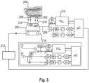
- FIG. 3 shows a further embodiment of the device.
- the device contains a terahertz transmitter-receiver chip (200) that emits terahertz radiation (202) into the body region (204) to be examined, e.g., a fingertip, and for detecting the terahertz radiation (206) reflected therefrom.
- the measurement signal from the chip (200) is passed via a fast Fourier transformation unit (210) to the evaluation unit (212), e.g., a CPU.
- the device contains at least one IR sensor (214) for detecting endogenous IR radiation (216) from the body region (204) to be examined.
- the measurement signal detected by the at least one IR sensor (214) is passed to the evaluation unit (212), where it is evaluated in combination with the terahertz measurement signal.
- FIG. 4 The detailed representation of an embodiment of the IR detection unit is shown in Figure 4 shown.
- a body region (14) of a test subject to be examined is introduced into the device.
- a body region with good blood circulation such as a fingertip, is preferably selected.
- the body region (14) rests on a support element (16) that is thermally insulated and contains a region (16a) that is at least partially optically transparent to the IR radiation (20) originating from the body region (14), i.e., at least in the range of the measuring wavelengths.
- the support element (16) contains means (16b) for determining the temperature of the body region to be examined, such as a fingertip (14), e.g., a temperature sensor.
- means, e.g., sensors, for detecting and/or monitoring the support position and/or the support pressure of the body region to be irradiated may be present (not shown).
- the support element may contain a temperature adjustment element (not shown).
- IR radiation (20) from the body region (14) to be examined originates at least partially from the near-surface blood capillaries in the dermis (18), which are located at a distance of approximately 2.5 to 3 mm from the body surface.
- An analyte located in the blood capillaries or, where appropriate, in the adjacent tissue will absorb the radiation within its specific absorption band, with the extent of absorption correlating with the analyte concentration.
- the device further includes a first sensor (22a) and a second sensor (22b) for separately detecting the body's own IR radiation at different wavelengths or wavelength ranges (20) in the region of preferably 8-12 ⁇ m.
- the first and second sensors can be designed as bolometers or thermopiles.
- the first and second sensors can also consist of arrays of individual sensor elements, e.g., 8 ⁇ 8 individual sensor elements.
- the first sensor (22a) is configured to selectively detect endogenous radiation with a first wavelength or a first wavelength range from an absorption minimum of glucose, wherein a first filter element (24a) is provided, which is selectively permeable to radiation with the first wavelength or with the first wavelength range. This means that the signal measured by the first sensor is essentially independent of the glucose concentration.
- the second sensor (22b) is in turn configured to selectively detect endogenous radiation (20) with a second wavelength or a second wavelength range from an absorption band, preferably in the region of an absorption maximum of glucose, wherein a second filter element (24b) is provided, which is selectively permeable to radiation with the second wavelength or with the second wavelength range. This means that the signal detected by the second sensor is dependent on the glucose concentration.
- two or more second sensors can be present, which can detect radiation with different wavelengths or wavelength ranges.
- two second sensors can be used, each separately detecting IR radiation in the range of 9.1 ⁇ m and 9.6 ⁇ m.
- the filter elements (24a, 24b) are advantageously arranged so that they rest directly on the respective sensors (22a, 22b).
- the device further comprises a third sensor (22c) which is configured for the non-specific detection of the body's own IR radiation (20) and serves for referencing, e.g. for referencing the body temperature in the body region (14) to be examined.
- a third sensor (22c) which is configured for the non-specific detection of the body's own IR radiation (20) and serves for referencing, e.g. for referencing the body temperature in the body region (14) to be examined.
- the sensors (22a, 22b, and optionally 22c) are in thermal equilibration by being in contact with a block (32) made of conductive material, e.g., metal, or embedded therein, e.g., by being arranged in a recess of the block.
- a block (32) made of conductive material, e.g., metal, or embedded therein, e.g., by being arranged in a recess of the block.
- the thermally conductive material can also be formed as a plate or foil.
- means (26) for determining the temperature of the block (24) containing the sensors (22a, 22b and optionally 22c), e.g. a temperature sensor, and means (28) for adjusting the temperature of the block (24) containing the sensors (22a, 22b and optionally 22c), e.g. cooling and/or heating elements, are provided.
- the signals from the sensors (22a, 22b and optionally 22c) as well as the temperatures determined by the elements (16b) and (26) are transmitted to a CPU unit (30), where, if necessary, the temperature for the sensors (22a, 22b and 22c) is adjusted to a value lower than the temperature of the body region to be examined, and a temperature-compensated evaluation of the signals is performed. Based on this evaluation, the glucose concentration is determined. The result can then be shown on a display. (32) are displayed.
- the inner side (34) of the measuring system can be completely or partially coated or equipped with a surface made of a material which does not reflect the IR radiation (20) originating from the body region (14) and/or absorbs the IR radiation (20) originating from the body region (14).
- the measuring system may further comprise a casing or housing that provides electrical and/or thermal insulation from the environment.
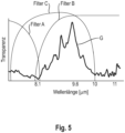
- FIG. 5 An alternative embodiment for the separate detection of the body’s own IR radiation at different wavelengths is described in Figure 5 shown.
- the absorption curve of glucose in the region between 8 and 14 ⁇ m is depicted as a bold line (G).
- two sensors are used, each comprising different combinations of bandpass, highpass, and/or lowpass filter elements.
- both sensors contain a wide bandpass filter (C) with a transmittance in the region between 8 and 14 ⁇ m.
- filter (C) is combined with a highpass filter (A) that is transparent to IR radiation with a wavelength of approximately 8.5 ⁇ m or less.
- a sensor equipped with filters (A) and (C) will therefore detect a signal from the 8-8.5 ⁇ m region that is essentially independent of the glucose concentration.
- the second sensor is equipped with a combination of a bandpass filter (C) and a lowpass filter (B), which is permeable to IR radiation with a wavelength of 8.5 ⁇ m or higher.
- the signal detected by this sensor comprises a glucose absorption band located in the region of approximately 9-10 ⁇ m and is therefore dependent on the glucose concentration.
- a first sensor can be equipped with the bandpass filter (C) and the highpass filter (A), while a second sensor is equipped only with the bandpass filter (C).
- the signal detected by the first sensor is independent of the glucose concentration, while the signal detected by the second sensor changes with the glucose concentration.
- Figure 6 shows a schematic cross-sectional view of another embodiment of the device's IR detection unit.
- the test subject's body region to be examined (not shown) is arranged on a thermally insulating support element (66) which contains a region (66a) that is at least partially optically transparent to IR radiation.
- the optically transparent region (66a) is a Si or Ge disk.
- the support element (66) is provided with a temperature sensor (66b) and, if appropriate, with a temperature adjustment element (not shown), which preferably comprises a Peltier element.
- the temperature of the body region can, for example, be adjusted to a range of approximately 28-38°C.
- the support element (66) contains means, e.g., sensors (68), for detecting and/or monitoring the contact pressure, such as a load cell, and, if appropriate, sensors for detecting and/or monitoring the contact position, such as a camera and/or a pulse sensor. It is advisable to set a contact pressure of approximately 1-50 N, e.g. approximately 20 N.
- the device further includes a first IR sensor (70a) and a second IR sensor (70b) for detecting the body's own IR radiation (72) with different wavelengths in the range of 0.7-20 ⁇ m, preferably 3-20 ⁇ m, from the examined body region.
- the first and second sensors can each be designed as bolometers or thermopiles. If necessary, the first and second sensors can also consist of arrays of individual sensor elements.
- the first sensor (70a) can be configured to selectively detect endogenous IR radiation at a first wavelength from an absorption minimum of the analyte, for example, wherein a first filter element (74a), e.g., a bandpass filter with narrow transmission, is provided, which is selectively permeable to radiation at the first wavelength, at which the signal is essentially independent of the concentration of the analyte to be determined.
- a first filter element (74a) e.g., a bandpass filter with narrow transmission
- the first wavelength is, for example, 8.1 ⁇ 0.3 ⁇ m and/or 8.5 ⁇ 0.3 ⁇ m, preferably 8.1 ⁇ 0.2 ⁇ m and/or 8.5 ⁇ 0.2 ⁇ m, particularly preferably 8.1 ⁇ 0.2 ⁇ m and/or 8.5 ⁇ 0.1 ⁇ m.
- the second sensor (74b) is in turn configured for selectively detecting endogenous IR radiation (72) having a second wavelength from an absorption band, preferably in the region of an absorption maximum of the analyte to be determined, wherein a second filter element (74b), e.g. a bandpass filter with narrow transmission, is provided, which is selectively permeable to radiation having the second wavelength.
- a second filter element (74b) e.g. a bandpass filter with narrow transmission
- the second wavelength is, for example, 9.1 ⁇ 0.3 ⁇ m, 9.3 ⁇ 0.3 ⁇ m, and/or 9.6 ⁇ 0.3 ⁇ m, preferably 9.1 ⁇ 0.2 ⁇ m, 9.3 ⁇ 0.2 ⁇ m, and/or 9.6 ⁇ 0.2 ⁇ m, particularly preferably in the range of 9.1 ⁇ 0.1 ⁇ m, 9.3 ⁇ 0.1 ⁇ m, and/or 9.6 ⁇ 0.1 ⁇ m.
- two or more second sensors can be present that can detect radiation with different wavelengths or wavelength ranges.
- two second sensors can be used, each of which separately detects IR radiation in the range of 9.1 ⁇ m or 9.3 ⁇ m and 9.6 ⁇ m.
- the filter elements (74a, 74b) are advantageously in direct contact with the sensors (70a, 70b).
- Optical focusing elements e.g., lens elements
- the sensors (70a, 70b) can optionally be equipped with optical lens elements, e.g., biconvex lenses, particularly spherical lenses, to enable focusing of the incident body's own IR radiation.
- the device further includes a third sensor (70c) configured for the non-specific detection of endogenous IR radiation (72) and for referencing, e.g., for the reference of the body temperature of the body region to be examined.
- the third sensor (70c) can be designed as a bolometer or thermopile.
- an intermediate wall (78) may be arranged between the first sensor (70a) and the second sensor (70b).
- the sensors (70a, 70b and optionally 70c) are in thermal equilibration by being in contact with thermally conductive material, e.g. a block (76), a plate or a foil made of metal.
- an element (80) for determining the temperature of the block (76) containing the sensors (70a, 70b, and 70c) is provided, e.g., a temperature sensor.
- an element (82) for adjusting the temperature of the block (76) containing the sensors (70a, 70b, and 70c) is provided, e.g., a cooling and/or heating element.
- the signals from the sensors (70a, 70b, and optionally 70c) as well as the temperatures determined by the elements (66b) and (80) are transmitted to a CPU unit (84) for temperature-compensated signal evaluation. Based on this evaluation, the analyte concentration is determined, and the result can then be shown on a display (86).
- the CPU unit can also be used to control the elements (68, 82).
- the inner surface of the measuring system can be coated with a material that does not reflect IR radiation and/or absorbs IR radiation. Furthermore, the measuring system can be thermally insulated from the environment.
- FIG. 7 A particularly preferred arrangement of sensors in the IR detection unit is shown in Figure 7 shown.
- Four IR sensors (90a, 90b, 90c, and 90d) are provided, which are arranged together in a recess of a metal block (not shown) and thus thermally equilibrated.
- each of the sensors consists of an array of several, e.g., 8 ⁇ 8, individual sensor elements.
- the sensors (90a, 90b) are intended for the selective detection of IR radiation with a wavelength from an absorption band of the analytes to be determined and are therefore equipped with corresponding filter elements.
- the senor (90a) can be provided for the selective detection of IR radiation with a wavelength of approximately 9.6 ⁇ m, e.g., 9.6 ⁇ 0.1 ⁇ m, and the sensor (90b) for the selective detection of IR radiation with a wavelength of approximately 9.1 ⁇ m, e.g., 9.1 ⁇ 0.1 ⁇ m, or approximately 9.3 ⁇ m, e.g., 9.3 ⁇ 0.1 ⁇ m.
- the sensor (90c) is provided for the selective detection of IR radiation with a wavelength from an absorption minimum of the analytes to be determined and are therefore equipped with corresponding filter elements.
- the senor (90c) can be provided for the selective detection of IR radiation with a wavelength of approximately 8.5 ⁇ m, e.g., 8.5 ⁇ 0.1 ⁇ m.
- the sensor (90d) does not contain a filter element and is used for referencing.
- a terahertz transmit/receive element (100) includes a terahertz radiation source (102), e.g., an antenna, and a terahertz detection unit (104).
- a terahertz radiation source 102
- a terahertz detection unit 104
- Terahertz radiation (106) emitted by the radiation source (102) is directed through a focusing lens (108), e.g., a spherical lens.
- the lens is made of a material transparent to terahertz radiation, such as polypropylene.
- the radiation (106) is focused by the lens (108) onto a predetermined zone (112) of the body region (110) to be examined, e.g., a finger (capillary blood area or saturated tissue).
- a predetermined zone (112) of the body region (110) to be examined e.g., a finger (capillary blood area or saturated tissue).
- the focusing occurs at a predetermined penetration depth, e.g., a penetration depth of 3-4 mm.
- the radiation (114) reflected by the focusing zone (112) is in turn guided through the lens (108), where it is focused onto the terahertz detection unit (104).
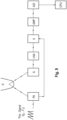
- a particularly preferred embodiment for evaluating a terahertz measurement signal is shown.
- a terahertz signal is frequency modulated over a range (f0...f1) containing an absorption band of glucose, the analyte to be determined.
- the modulation can be continuous, e.g., by changing the voltage with a voltage-controlled oscillator (VCO), or discontinuous.
- VCO voltage-controlled oscillator
- the frequency-modulated terahertz signal is transmitted to an antenna, e.g. a patch antenna (PA), and is then radiated to the body area (K) to be examined, e.g. a finger. This can be done via a lens (see e.g. Figure 8 ) or a waveguide. There, the terahertz radiation is reflected and reaches a sensor (S), e.g., a patch antenna or a dipole, and from there to a preamplifier, e.g., an LNA.
- a sensor e.g., a patch antenna or a dipole
- One or more phases of the signal are sent to an A/D converter and evaluated by a CPU.
- the evaluation preferably includes a continuously performed Fast Fourier Transformation (FFT) to filter out unwanted interference signals.
- FFT Fast Fourier Transformation
- the terahertz signal can also be used as A pulse-modulated signal is radiated onto the body area to be examined, with signal pulses, in particular discrete signal pulses each with a different frequency, being radiated at predetermined time intervals.
Landscapes
- Health & Medical Sciences (AREA)
- Life Sciences & Earth Sciences (AREA)
- Physics & Mathematics (AREA)
- Engineering & Computer Science (AREA)
- Biomedical Technology (AREA)
- General Health & Medical Sciences (AREA)
- Pathology (AREA)
- Molecular Biology (AREA)
- Biophysics (AREA)
- Heart & Thoracic Surgery (AREA)
- Medical Informatics (AREA)
- Surgery (AREA)
- Animal Behavior & Ethology (AREA)
- Public Health (AREA)
- Veterinary Medicine (AREA)
- Chemical & Material Sciences (AREA)
- Spectroscopy & Molecular Physics (AREA)
- Optics & Photonics (AREA)
- Analytical Chemistry (AREA)
- Biochemistry (AREA)
- General Physics & Mathematics (AREA)
- Immunology (AREA)
- Hematology (AREA)
- Emergency Medicine (AREA)
- Nuclear Medicine, Radiotherapy & Molecular Imaging (AREA)
- Radiology & Medical Imaging (AREA)
- Toxicology (AREA)
- Ecology (AREA)
- Urology & Nephrology (AREA)
- Food Science & Technology (AREA)
- Medicinal Chemistry (AREA)
- Investigating Or Analysing Materials By Optical Means (AREA)
- Measurement Of The Respiration, Hearing Ability, Form, And Blood Characteristics Of Living Organisms (AREA)
- Investigating Or Analysing Biological Materials (AREA)
- Radiation Pyrometers (AREA)
Applications Claiming Priority (2)
| Application Number | Priority Date | Filing Date | Title |
|---|---|---|---|
| EP19200618 | 2019-09-30 | ||
| PCT/EP2020/076023 WO2021063696A1 (de) | 2019-09-30 | 2020-09-17 | Nicht-invasive bestimmung von glucose |
Publications (3)
| Publication Number | Publication Date |
|---|---|
| EP4037560A1 EP4037560A1 (de) | 2022-08-10 |
| EP4037560B1 true EP4037560B1 (de) | 2025-03-26 |
| EP4037560C0 EP4037560C0 (de) | 2025-03-26 |
Family
ID=68424561
Family Applications (2)
| Application Number | Title | Priority Date | Filing Date |
|---|---|---|---|
| EP20771873.5A Active EP4037560B1 (de) | 2019-09-30 | 2020-09-17 | Nicht-invasive bestimmung von glukose |
| EP20771872.7A Active EP4037559B1 (de) | 2019-09-30 | 2020-09-17 | Vorrichtung und verfahren zur nicht-invasiven bestimmung von analyten |
Family Applications After (1)
| Application Number | Title | Priority Date | Filing Date |
|---|---|---|---|
| EP20771872.7A Active EP4037559B1 (de) | 2019-09-30 | 2020-09-17 | Vorrichtung und verfahren zur nicht-invasiven bestimmung von analyten |
Country Status (9)
| Country | Link |
|---|---|
| US (2) | US20220338765A1 (https=) |
| EP (2) | EP4037560B1 (https=) |
| JP (2) | JP7608445B2 (https=) |
| CN (2) | CN114727775A (https=) |
| AU (2) | AU2020360444B2 (https=) |
| BR (2) | BR112022005823A2 (https=) |
| CA (2) | CA3156102A1 (https=) |
| MX (2) | MX2022003811A (https=) |
| WO (2) | WO2021063696A1 (https=) |
Families Citing this family (4)
| Publication number | Priority date | Publication date | Assignee | Title |
|---|---|---|---|---|
| US12344406B1 (en) * | 2021-08-17 | 2025-07-01 | Hrl Laboratories, Llc | High temperature RF surface aperture |
| KR102681358B1 (ko) * | 2023-01-17 | 2024-07-04 | 주식회사 뷰텔 | 온도를 반영하여 포도당을 보정하는 비침습 포도당 측정 장치 및 방법 |
| GB2629609A (en) * | 2023-05-03 | 2024-11-06 | Univ Warwick | Terahertz scanning system |
| EP4725412A1 (en) | 2024-10-12 | 2026-04-15 | Walletmed Limited | Implant and method of metabolite measurement |
Family Cites Families (58)
| Publication number | Priority date | Publication date | Assignee | Title |
|---|---|---|---|---|
| US5615672A (en) * | 1993-01-28 | 1997-04-01 | Optiscan, Inc. | Self-emission noninvasive infrared spectrophotometer with body temperature compensation |
| US5515847A (en) * | 1993-01-28 | 1996-05-14 | Optiscan, Inc. | Self-emission noninvasive infrared spectrophotometer |
| US8019400B2 (en) * | 1994-10-07 | 2011-09-13 | Masimo Corporation | Signal processing apparatus |
| JP4212007B2 (ja) * | 1996-11-26 | 2009-01-21 | パナソニック電工株式会社 | 血液成分濃度の分析装置 |
| GB2329015B (en) * | 1997-09-05 | 2002-02-13 | Samsung Electronics Co Ltd | Method and device for noninvasive measurement of concentrations of blood components |
| FR2810108B1 (fr) * | 2000-06-09 | 2004-04-02 | France Telecom | Ellipsometre spectroscopique a faible bruit |
| GB2396695B (en) * | 2001-01-16 | 2005-05-04 | Teraview Ltd | Apparatus and method for investigating a sample |
| WO2003017745A2 (en) * | 2001-08-23 | 2003-03-06 | Sciperio, Inc. | Architecture tool and methods of use |
| DE102004035635A1 (de) * | 2004-07-22 | 2006-04-06 | Philipps-Universität Marburg | Erfindung betreffend Emitterelemente elektromagnetischer Strahlung sowie Verfahren zur Erzeugung von Besetzungsinversionen in solchen Emitterelementen |
| CN101184440A (zh) * | 2005-06-07 | 2008-05-21 | 欧姆龙健康医疗事业株式会社 | 生物体信息计测传感器 |
| US7378658B2 (en) * | 2005-09-20 | 2008-05-27 | Coherent, Inc. | Security portal with THz trans-receiver |
| KR20070034169A (ko) * | 2005-09-23 | 2007-03-28 | 삼성전자주식회사 | 테라헤르츠파를 이용한 혈중 성분 농도 측정 장치 및 방법 |
| WO2007071092A1 (en) * | 2005-12-21 | 2007-06-28 | Etech Ag | Blood glucose sensor based on reflection or transmission spectroscopy at frequencies in the terahertz region and above the terahertz region |
| US8135450B2 (en) * | 2006-01-20 | 2012-03-13 | Esenaliev Rinat O | Noninvasive glucose sensing methods and systems |
| US7729734B2 (en) * | 2006-03-07 | 2010-06-01 | Andreas Mandelis | Non-invasive biothermophotonic sensor for blood glucose monitoring |
| JP5132146B2 (ja) * | 2006-03-17 | 2013-01-30 | キヤノン株式会社 | 分析方法、分析装置、及び検体保持部材 |
| JP4861220B2 (ja) * | 2006-08-28 | 2012-01-25 | キヤノン株式会社 | 電磁波を用いた検査装置 |
| CN1996029A (zh) * | 2006-12-25 | 2007-07-11 | 欧阳征标 | THz信号高灵敏度探测器与摄像头 |
| US7795582B2 (en) * | 2007-10-19 | 2010-09-14 | Honeywell International Inc. | System and method of monitoring with temperature stabilization |
| US8611975B2 (en) * | 2009-10-28 | 2013-12-17 | Gluco Vista, Inc. | Apparatus and method for non-invasive measurement of a substance within a body |
| US8401604B2 (en) * | 2008-04-11 | 2013-03-19 | Glucovista, Llc | Apparatus and methods for non-invasive measurement of a substance within a body |
| US9117133B2 (en) * | 2008-06-18 | 2015-08-25 | Spectral Image, Inc. | Systems and methods for hyperspectral imaging |
| JP5353121B2 (ja) * | 2008-08-26 | 2013-11-27 | アイシン精機株式会社 | テラヘルツ波発生装置およびテラヘルツ波発生方法 |
| NZ600888A (en) * | 2010-02-12 | 2014-04-30 | Advanced Fusion Systems Llc | Method and system for detecting materials |
| US10188325B2 (en) | 2012-03-09 | 2019-01-29 | Rinat O. Esenaliev | Wearable, noninvasive glucose sensing methods and systems |
| US10607507B2 (en) * | 2015-11-24 | 2020-03-31 | Medibotics | Arcuate wearable device with a circumferential or annular array of spectroscopic sensors for measuring hydration level |
| US20170164878A1 (en) * | 2012-06-14 | 2017-06-15 | Medibotics Llc | Wearable Technology for Non-Invasive Glucose Monitoring |
| EP2879577A1 (en) | 2012-08-01 | 2015-06-10 | California Institute of Technology | Cardiac microwave signal determination of cardiovascular diseases |
| US9658155B2 (en) * | 2012-12-17 | 2017-05-23 | Patrick K Brady | System and method for identifying materials using a THz spectral fingerprint in a media with high water content |
| US9494464B2 (en) * | 2013-02-20 | 2016-11-15 | Battelle Energy Alliance, Llc | Terahertz imaging devices and systems, and related methods, for detection of materials |
| DE102013010611A1 (de) | 2013-06-25 | 2015-01-08 | Sms Swiss Medical Sensor Ag | Messvorrichtung und Messverfahren zum Messen von Rohdaten zur Bestimmung eines Blutparameters, insbesondere zur nichtinvasiven Bestimmung der D-Glucose-Konzentration |
| US20150112170A1 (en) * | 2013-10-17 | 2015-04-23 | Amerson, Llc | Device and method for non-invasive glucose monitoring |
| GB201318493D0 (en) * | 2013-10-18 | 2013-12-04 | Cambridge Entpr Ltd | Method and apparatus for characterising amorphous mateials |
| US11229383B2 (en) * | 2014-08-25 | 2022-01-25 | California Institute Of Technology | Methods and systems for non-invasive measurement of blood glucose concentration by transmission of millimeter waves through human skin |
| US9618824B2 (en) * | 2014-09-27 | 2017-04-11 | Intel Corporation | Integrated Terahertz sensor |
| US10092209B2 (en) * | 2014-10-03 | 2018-10-09 | Advantest Corporation | Non-invasive in situ glucose level sensing using electromagnetic radiation |
| EP3244793A1 (de) | 2015-02-11 | 2017-11-22 | Siemens Aktiengesellschaft | Anordnung und verfahren zur nicht-invasiven untersuchung von zumindest teilen der blutbestandteile und verwendung der anordnung |
| WO2016139155A1 (de) * | 2015-03-03 | 2016-09-09 | Sikora Ag | Vorrichtung und verfahren zum messen des durchmessers und/oder der wanddicke eines strangs |
| JP6389135B2 (ja) * | 2015-03-30 | 2018-09-12 | 日本電信電話株式会社 | 成分濃度分析装置および成分濃度分析方法 |
| CN205251548U (zh) | 2015-05-15 | 2016-05-25 | 深圳市一体太糖科技有限公司 | 一种太赫兹血糖测量装置 |
| US11653862B2 (en) * | 2015-05-22 | 2023-05-23 | Cercacor Laboratories, Inc. | Non-invasive optical physiological differential pathlength sensor |
| US10321860B2 (en) * | 2015-07-19 | 2019-06-18 | Sanmina Corporation | System and method for glucose monitoring |
| US11419543B1 (en) * | 2016-03-03 | 2022-08-23 | Gholam A. Peyman | Early disease detection and therapy |
| WO2018000122A1 (zh) | 2016-06-27 | 2018-01-04 | 祁家亮 | 自拍装置 |
| US20190183398A1 (en) * | 2016-08-19 | 2019-06-20 | Eccrine Systems, Inc. | Biofluid sensing devices with temperature regulation |
| JP6696691B2 (ja) * | 2016-09-05 | 2020-05-20 | 株式会社東芝 | テラヘルツ量子カスケードレーザ装置 |
| WO2018122319A1 (de) | 2016-12-30 | 2018-07-05 | Swiss Spectral Ag | Vorrichtung und verfahren zur nicht-invasiven bestimmung von analyten |
| WO2018207815A1 (ja) * | 2017-05-09 | 2018-11-15 | 国立大学法人東京工業大学 | テラヘルツ波検出装置およびテラヘルツ波検出システム |
| EP3443887A1 (de) | 2017-08-18 | 2019-02-20 | Swiss Spectral AG | Vorrichtung und verfahren zur nicht-invasiven bestimmung von analyten ohne externe strahlungsquelle |
| US20200221969A1 (en) * | 2017-09-05 | 2020-07-16 | Epitronic Holdings Pte. Ltd. | Microelectronic sensors for sensing electrical signals from a human body in a sub-terahertz range |
| US10935368B2 (en) * | 2018-03-14 | 2021-03-02 | Honeywell Limited | Scanning caliper and basis weight sensor for sheet products using terahertz |
| TWI673554B (zh) * | 2018-08-22 | 2019-10-01 | 國立清華大學 | 液晶光電裝置及光學影像處理系統 |
| US10871444B2 (en) * | 2018-08-30 | 2020-12-22 | Saudi Arabian Oil Company | Inspection and failure detection of corrosion under fireproofing insulation using a hybrid sensory system |
| DE102018124175A1 (de) * | 2018-10-01 | 2020-04-02 | Sikora Ag | Verfahren und Vorrichtung zum Steuern einer Produktionsanlage für plattenförmige oder strangförmige Körper |
| WO2020131349A1 (en) * | 2018-12-18 | 2020-06-25 | Analog Devices, Inc. | Cloud-based portable system for non-invasive real-time urinalysis |
| CN110141248A (zh) * | 2019-05-21 | 2019-08-20 | 上海理工大学 | 基于衰减全反射太赫兹介电谱标定血糖浓度的装置及方法 |
| US11555792B2 (en) | 2019-08-08 | 2023-01-17 | Apple Inc. | Terahertz spectroscopy and imaging in dynamic environments with performance enhancements using ambient sensors |
| AU2020331683B2 (en) * | 2019-08-16 | 2025-08-14 | Glucomat Gmbh | Active miniaturized sensing system and method |
-
2020
- 2020-09-17 EP EP20771873.5A patent/EP4037560B1/de active Active
- 2020-09-17 AU AU2020360444A patent/AU2020360444B2/en not_active Expired - Fee Related
- 2020-09-17 US US17/764,920 patent/US20220338765A1/en active Pending
- 2020-09-17 MX MX2022003811A patent/MX2022003811A/es unknown
- 2020-09-17 CA CA3156102A patent/CA3156102A1/en active Pending
- 2020-09-17 CA CA3156108A patent/CA3156108A1/en active Pending
- 2020-09-17 WO PCT/EP2020/076023 patent/WO2021063696A1/de not_active Ceased
- 2020-09-17 AU AU2020360024A patent/AU2020360024B2/en not_active Expired - Fee Related
- 2020-09-17 EP EP20771872.7A patent/EP4037559B1/de active Active
- 2020-09-17 JP JP2022520012A patent/JP7608445B2/ja active Active
- 2020-09-17 JP JP2022520011A patent/JP7524314B2/ja active Active
- 2020-09-17 WO PCT/EP2020/076022 patent/WO2021063695A1/de not_active Ceased
- 2020-09-17 BR BR112022005823A patent/BR112022005823A2/pt not_active Application Discontinuation
- 2020-09-17 MX MX2022003812A patent/MX2022003812A/es unknown
- 2020-09-17 BR BR112022006013A patent/BR112022006013A2/pt not_active Application Discontinuation
- 2020-09-17 US US17/764,715 patent/US12458255B2/en active Active
- 2020-09-17 CN CN202080078370.0A patent/CN114727775A/zh active Pending
- 2020-09-17 CN CN202080080946.7A patent/CN114727776A/zh active Pending
Also Published As
| Publication number | Publication date |
|---|---|
| CN114727776A (zh) | 2022-07-08 |
| JP7524314B2 (ja) | 2024-07-29 |
| CA3156108A1 (en) | 2021-04-08 |
| WO2021063695A1 (de) | 2021-04-08 |
| BR112022005823A2 (pt) | 2022-06-21 |
| WO2021063696A1 (de) | 2021-04-08 |
| CA3156102A1 (en) | 2021-04-08 |
| MX2022003811A (es) | 2022-07-11 |
| JP2022549958A (ja) | 2022-11-29 |
| EP4037559A1 (de) | 2022-08-10 |
| CN114727775A (zh) | 2022-07-08 |
| AU2020360444B2 (en) | 2025-10-02 |
| US20220409105A1 (en) | 2022-12-29 |
| EP4037560C0 (de) | 2025-03-26 |
| US12458255B2 (en) | 2025-11-04 |
| EP4037560A1 (de) | 2022-08-10 |
| JP7608445B2 (ja) | 2025-01-06 |
| EP4037559B1 (de) | 2025-03-26 |
| AU2020360024A1 (en) | 2022-05-19 |
| AU2020360024B2 (en) | 2025-08-28 |
| US20220338765A1 (en) | 2022-10-27 |
| EP4037559C0 (de) | 2025-03-26 |
| BR112022006013A2 (pt) | 2022-07-12 |
| AU2020360444A1 (en) | 2022-05-19 |
| JP2022549959A (ja) | 2022-11-29 |
| MX2022003812A (es) | 2022-07-11 |
Similar Documents
| Publication | Publication Date | Title |
|---|---|---|
| EP4037560B1 (de) | Nicht-invasive bestimmung von glukose | |
| EP3495800B1 (de) | Vorrichtung und verfahren zum analysieren eines stoffs | |
| EP3721225B1 (de) | Vorrichtung und verfahren zum analysieren eines stoffs | |
| DE68902738T2 (de) | Verfahren zur bestimmung mittels strahlungsabsorption von substanzen in absorbierenden und streuenden matrixmaterialien. | |
| EP0726729B1 (de) | Verfahren und vorrichtung zur analyse von glucose in einer biologischen matrix | |
| CN100406872C (zh) | 复合光谱测量方法及其光谱检测仪器 | |
| EP0760091B1 (de) | Verfahren und vorrichtung zur bestimmung eines analyten in einer biologischen probe | |
| HK1055552A1 (en) | Method and device for detecting substances in body fluids by raman spectroscopy | |
| EP0707826A1 (de) | Verfahren und Vorrichtung zur Analyse von Glukose in einer biologischen Matrix | |
| DE102017126712B4 (de) | Radarspektroskopie-basierter gassensor | |
| WO2018122319A1 (de) | Vorrichtung und verfahren zur nicht-invasiven bestimmung von analyten | |
| WO2019034722A1 (de) | Vorrichtung und verfahren zur nicht-invasiven bestimmung von analyten ohne externe strahlungsquelle | |
| DE60301764T2 (de) | Gerät und Verfahren zum Nachweis von Zirkulardichroismus im Infrarotbereich | |
| WO2011015298A1 (de) | Thz-spektroskop und verfahren zur bestimmung der spektralen frequenz- und / oder phasenantwort einer probe | |
| Golparvar et al. | Single-Band Raman shift detection for Spectroscopy-Less optical biosensors | |
| Youcef-Toumi et al. | Noninvasive blood glucose analysis using near infrared absorption spectroscopy | |
| JP2003149145A (ja) | 血糖値の無侵襲測定装置 | |
| DE60126600T2 (de) | Analyseverfahren für stoffmischungen | |
| DE102007005642A1 (de) | Vorrichtung und Verfahren zur spektralen Diagnostik von Substanzen und/oder Oberflächen | |
| EP4693771A1 (de) | Anregungsquelle zur einstrahlung von anregungsstrahlung in ein volumen sowie vorrichtung zum nachweis eines stoffes mit einer solchen anregungsquelle | |
| EP4692762A1 (de) | Verfahren und vorrichtung zum nachweis eines stoffs in einer probe, die infrarotstrahlung absorbiert hat, unter berücksichtigung ihrer absorptionscharakteristik | |
| EP4691346A1 (de) | Vorrichtung zur erfassung einer stoffkonzentration | |
| DE102012219674B4 (de) | Verfahren zur berührungslosen Teilchengrößenanalyse eines Granulats sowie Messvorrichtung zur berührungslosen Teilchengrößenanalyse | |
| Kaur et al. | Design and Realization of NIR Optical Spectroscopy Systems | |
| DE102005039021A1 (de) | Nicht-invasives quantitatives Blutinhaltsstoffanalysegerät |
Legal Events
| Date | Code | Title | Description |
|---|---|---|---|
| STAA | Information on the status of an ep patent application or granted ep patent |
Free format text: STATUS: UNKNOWN |
|
| STAA | Information on the status of an ep patent application or granted ep patent |
Free format text: STATUS: THE INTERNATIONAL PUBLICATION HAS BEEN MADE |
|
| PUAI | Public reference made under article 153(3) epc to a published international application that has entered the european phase |
Free format text: ORIGINAL CODE: 0009012 |
|
| STAA | Information on the status of an ep patent application or granted ep patent |
Free format text: STATUS: REQUEST FOR EXAMINATION WAS MADE |
|
| 17P | Request for examination filed |
Effective date: 20220330 |
|
| AK | Designated contracting states |
Kind code of ref document: A1 Designated state(s): AL AT BE BG CH CY CZ DE DK EE ES FI FR GB GR HR HU IE IS IT LI LT LU LV MC MK MT NL NO PL PT RO RS SE SI SK SM TR |
|
| DAV | Request for validation of the european patent (deleted) | ||
| DAX | Request for extension of the european patent (deleted) | ||
| STAA | Information on the status of an ep patent application or granted ep patent |
Free format text: STATUS: EXAMINATION IS IN PROGRESS |
|
| 17Q | First examination report despatched |
Effective date: 20230327 |
|
| GRAP | Despatch of communication of intention to grant a patent |
Free format text: ORIGINAL CODE: EPIDOSNIGR1 |
|
| STAA | Information on the status of an ep patent application or granted ep patent |
Free format text: STATUS: GRANT OF PATENT IS INTENDED |
|
| INTG | Intention to grant announced |
Effective date: 20241016 |
|
| GRAS | Grant fee paid |
Free format text: ORIGINAL CODE: EPIDOSNIGR3 |
|
| GRAA | (expected) grant |
Free format text: ORIGINAL CODE: 0009210 |
|
| STAA | Information on the status of an ep patent application or granted ep patent |
Free format text: STATUS: THE PATENT HAS BEEN GRANTED |
|
| AK | Designated contracting states |
Kind code of ref document: B1 Designated state(s): AL AT BE BG CH CY CZ DE DK EE ES FI FR GB GR HR HU IE IS IT LI LT LU LV MC MK MT NL NO PL PT RO RS SE SI SK SM TR |
|
| REG | Reference to a national code |
Ref country code: GB Ref legal event code: FG4D Free format text: NOT ENGLISH |
|
| REG | Reference to a national code |
Ref country code: CH Ref legal event code: EP |
|
| REG | Reference to a national code |
Ref country code: DE Ref legal event code: R096 Ref document number: 502020010702 Country of ref document: DE |
|
| REG | Reference to a national code |
Ref country code: IE Ref legal event code: FG4D Free format text: LANGUAGE OF EP DOCUMENT: GERMAN |
|
| U01 | Request for unitary effect filed |
Effective date: 20250417 |
|
| U07 | Unitary effect registered |
Designated state(s): AT BE BG DE DK EE FI FR IT LT LU LV MT NL PT RO SE SI Effective date: 20250425 |
|
| PG25 | Lapsed in a contracting state [announced via postgrant information from national office to epo] |
Ref country code: RS Free format text: LAPSE BECAUSE OF FAILURE TO SUBMIT A TRANSLATION OF THE DESCRIPTION OR TO PAY THE FEE WITHIN THE PRESCRIBED TIME-LIMIT Effective date: 20250626 |
|
| PG25 | Lapsed in a contracting state [announced via postgrant information from national office to epo] |
Ref country code: NO Free format text: LAPSE BECAUSE OF FAILURE TO SUBMIT A TRANSLATION OF THE DESCRIPTION OR TO PAY THE FEE WITHIN THE PRESCRIBED TIME-LIMIT Effective date: 20250626 |
|
| PG25 | Lapsed in a contracting state [announced via postgrant information from national office to epo] |
Ref country code: HR Free format text: LAPSE BECAUSE OF FAILURE TO SUBMIT A TRANSLATION OF THE DESCRIPTION OR TO PAY THE FEE WITHIN THE PRESCRIBED TIME-LIMIT Effective date: 20250326 |
|
| PG25 | Lapsed in a contracting state [announced via postgrant information from national office to epo] |
Ref country code: GR Free format text: LAPSE BECAUSE OF FAILURE TO SUBMIT A TRANSLATION OF THE DESCRIPTION OR TO PAY THE FEE WITHIN THE PRESCRIBED TIME-LIMIT Effective date: 20250627 |
|
| U20 | Renewal fee for the european patent with unitary effect paid |
Year of fee payment: 6 Effective date: 20250821 |
|
| REG | Reference to a national code |
Ref country code: CH Ref legal event code: U11 Free format text: ST27 STATUS EVENT CODE: U-0-0-U10-U11 (AS PROVIDED BY THE NATIONAL OFFICE) Effective date: 20251001 |
|
| PG25 | Lapsed in a contracting state [announced via postgrant information from national office to epo] |
Ref country code: SM Free format text: LAPSE BECAUSE OF FAILURE TO SUBMIT A TRANSLATION OF THE DESCRIPTION OR TO PAY THE FEE WITHIN THE PRESCRIBED TIME-LIMIT Effective date: 20250326 |
|
| PG25 | Lapsed in a contracting state [announced via postgrant information from national office to epo] |
Ref country code: ES Free format text: LAPSE BECAUSE OF FAILURE TO SUBMIT A TRANSLATION OF THE DESCRIPTION OR TO PAY THE FEE WITHIN THE PRESCRIBED TIME-LIMIT Effective date: 20250326 |
|
| PG25 | Lapsed in a contracting state [announced via postgrant information from national office to epo] |
Ref country code: PL Free format text: LAPSE BECAUSE OF FAILURE TO SUBMIT A TRANSLATION OF THE DESCRIPTION OR TO PAY THE FEE WITHIN THE PRESCRIBED TIME-LIMIT Effective date: 20250326 |
|
| PGFP | Annual fee paid to national office [announced via postgrant information from national office to epo] |
Ref country code: GB Payment date: 20250919 Year of fee payment: 6 |
|
| PG25 | Lapsed in a contracting state [announced via postgrant information from national office to epo] |
Ref country code: SK Free format text: LAPSE BECAUSE OF FAILURE TO SUBMIT A TRANSLATION OF THE DESCRIPTION OR TO PAY THE FEE WITHIN THE PRESCRIBED TIME-LIMIT Effective date: 20250326 |
|
| PG25 | Lapsed in a contracting state [announced via postgrant information from national office to epo] |
Ref country code: IS Free format text: LAPSE BECAUSE OF FAILURE TO SUBMIT A TRANSLATION OF THE DESCRIPTION OR TO PAY THE FEE WITHIN THE PRESCRIBED TIME-LIMIT Effective date: 20250726 |
|
| PGFP | Annual fee paid to national office [announced via postgrant information from national office to epo] |
Ref country code: CH Payment date: 20251001 Year of fee payment: 6 |
|
| PG25 | Lapsed in a contracting state [announced via postgrant information from national office to epo] |
Ref country code: CZ Free format text: LAPSE BECAUSE OF FAILURE TO SUBMIT A TRANSLATION OF THE DESCRIPTION OR TO PAY THE FEE WITHIN THE PRESCRIBED TIME-LIMIT Effective date: 20250326 |
|
| PLBE | No opposition filed within time limit |
Free format text: ORIGINAL CODE: 0009261 |
|
| STAA | Information on the status of an ep patent application or granted ep patent |
Free format text: STATUS: NO OPPOSITION FILED WITHIN TIME LIMIT |
|
| REG | Reference to a national code |
Ref country code: CH Ref legal event code: L10 Free format text: ST27 STATUS EVENT CODE: U-0-0-L10-L00 (AS PROVIDED BY THE NATIONAL OFFICE) Effective date: 20260211 |
|
| 26N | No opposition filed |
Effective date: 20260105 |