EP4037447B1 - Peripherieüberwachungsvorrichtung - Google Patents
Peripherieüberwachungsvorrichtung Download PDFInfo
- Publication number
- EP4037447B1 EP4037447B1 EP19946278.9A EP19946278A EP4037447B1 EP 4037447 B1 EP4037447 B1 EP 4037447B1 EP 19946278 A EP19946278 A EP 19946278A EP 4037447 B1 EP4037447 B1 EP 4037447B1
- Authority
- EP
- European Patent Office
- Prior art keywords
- monitoring area
- monitoring
- feeder
- automatic exchange
- moving body
- Prior art date
- Legal status (The legal status is an assumption and is not a legal conclusion. Google has not performed a legal analysis and makes no representation as to the accuracy of the status listed.)
- Active
Links
Images


Classifications
-
- H—ELECTRICITY
- H05—ELECTRIC TECHNIQUES NOT OTHERWISE PROVIDED FOR
- H05K—PRINTED CIRCUITS; CASINGS OR CONSTRUCTIONAL DETAILS OF ELECTRIC APPARATUS; MANUFACTURE OF ASSEMBLAGES OF ELECTRICAL COMPONENTS
- H05K13/00—Apparatus or processes specially adapted for manufacturing or adjusting assemblages of electric components
- H05K13/08—Monitoring manufacture of assemblages
- H05K13/0888—Ergonomics; Operator safety; Training; Failsafe systems
-
- H—ELECTRICITY
- H05—ELECTRIC TECHNIQUES NOT OTHERWISE PROVIDED FOR
- H05K—PRINTED CIRCUITS; CASINGS OR CONSTRUCTIONAL DETAILS OF ELECTRIC APPARATUS; MANUFACTURE OF ASSEMBLAGES OF ELECTRICAL COMPONENTS
- H05K13/00—Apparatus or processes specially adapted for manufacturing or adjusting assemblages of electric components
- H05K13/08—Monitoring manufacture of assemblages
- H05K13/081—Integration of optical monitoring devices in assembly lines; Processes using optical monitoring devices specially adapted for controlling devices or machines in assembly lines
-
- B—PERFORMING OPERATIONS; TRANSPORTING
- B25—HAND TOOLS; PORTABLE POWER-DRIVEN TOOLS; MANIPULATORS
- B25J—MANIPULATORS; CHAMBERS PROVIDED WITH MANIPULATION DEVICES
- B25J13/00—Controls for manipulators
- B25J13/08—Controls for manipulators by means of sensing devices, e.g. viewing or touching devices
-
- B—PERFORMING OPERATIONS; TRANSPORTING
- B25—HAND TOOLS; PORTABLE POWER-DRIVEN TOOLS; MANIPULATORS
- B25J—MANIPULATORS; CHAMBERS PROVIDED WITH MANIPULATION DEVICES
- B25J9/00—Programme-controlled manipulators
- B25J9/16—Programme controls
- B25J9/1674—Programme controls characterised by safety, monitoring, diagnostic
- B25J9/1676—Avoiding collision or forbidden zones
-
- H—ELECTRICITY
- H05—ELECTRIC TECHNIQUES NOT OTHERWISE PROVIDED FOR
- H05K—PRINTED CIRCUITS; CASINGS OR CONSTRUCTIONAL DETAILS OF ELECTRIC APPARATUS; MANUFACTURE OF ASSEMBLAGES OF ELECTRICAL COMPONENTS
- H05K13/00—Apparatus or processes specially adapted for manufacturing or adjusting assemblages of electric components
- H05K13/02—Feeding of components
Definitions
- the present specification relates to a technology regarding a periphery monitoring device for monitoring at least three directions of a moving body.
- Patent Literature 1 International Publication No. WO2019/087392
- a feeder automatic exchange robot has been movably provided in a moving lane provided along an array of multiple component mounters constituting a component mounting line, the feeder automatic exchange robot has been moved to a front side of a component mounter for which an automatic exchange request was generated, so that the feeder is automatically exchanged with respect to a feeder setting base of the component mounter.
- US 2018/111269 A1 is known from US 2018/111269 A1 .
- Patent Literature 1 International Publication No. WO2019/087392
- a monitoring area monitored by a safety laser scanner provided in a corner portion of a lower portion of a front surface of a feeder automatic exchange robot is a horizontal plane-like monitoring area which is two-dimensionally monitored in a horizontal direction along a floor surface.
- the conventional monitoring area is set so as to detect the foot of the operator, if the foot of the operator is outside the monitoring area, it is impossible to perform the detection even if the fingertip of the operator extends toward the feeder automatic exchange robot above the monitoring area. Therefore, in order to ensure security, it is necessary to set a large monitoring area in consideration of a range in which the fingertip of the operator extends.
- the larger the monitoring area the greater the frequency at which the operator inadvertently intrudes and is detected in the monitoring area is, thereby increasing the frequency at which the operation of the feeder automatic exchange robot is stopped in an emergency manner, and reducing the productivity.
- the larger the monitoring area the narrower a work area in which the operator can safely operate, so that the efficiency is also reduced.
- Component mounting line 10 is configured by arranging multiple component mounters 12 in a row along a conveyance direction (X-direction) of circuit board 11, and a solder printer (not illustrated) for printing solder on circuit board 11, feeder storage device 19 for storing cassette-type feeders 14, and the like are installed on a board loading side of component mounting line 10.
- each component mounter 12 is provided with two conveyors 13 for conveying circuit board 11, feeder setting base 24 (see Fig. 1 ) for exchangeably setting multiple cassette-type feeders 14, mounting head 15 for holding a suction nozzle (not illustrated) for picking up a component supplied from cassette-type feeder 14 set on feeder setting base 24 and mounting the same on circuit board 11, head moving device 16 for moving mounting head 15 in XY-directions (left-right and front-rear directions), component imaging camera 17 (see Fig. 5 ) for imaging the component picked up by the suction nozzle from below, and the like.
- Mark imaging camera 18 (see Fig. 5 ) for imaging a reference mark (not illustrated) of circuit board 11 is attached to head moving device 16 so as to move integrally with mounting head 15 in XY-directions.
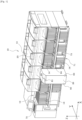
- Feeder automatic exchange robot 26 moves to the front side of component mounter 12 for which an automatic exchange request has generated when the automatic exchange request for feeder 14 generates in any of multiple component mounters 12 constituting component mounting line 10, takes out feeder 14 of an exchange target from feeder setting base 24 of component mounter 12, collects feeder 14 in stock section 71, and takes out necessary feeder 14 from stock section 71 to set feeder 14 in feeder setting base 24.
- Feeder automatic exchange robot 26 may perform only an operation of collecting feeder 14 taken out from feeder setting base 24 into stock section 71 in response to the automatic exchange request, or conversely, may perform only an operation of setting feeder 14 taken out from stock section 71 in an empty slot of feeder setting base 24.
- guide rail 75 for moving feeder automatic exchange robot 26 (moving body) in X-direction (right-left direction) along the array of component mounters 12 is provided so as to extend in X-direction over entire component mounting line 10.
- a board loading side of guide rail 75 extends to feeder storage device 19, so that feeder automatic exchange robot 26 moves to the front side of feeder storage device 19 so that feeder automatic exchange robot 26 takes out feeder 14 necessary for the automatic exchange from feeder storage device 19 or returns used feeder 14 into feeder storage device 19.
- Feeder automatic exchange robot 26 is provided with position detection device 34 (see Fig. 5 ) for detecting the position of feeder automatic exchange robot 26 with respect to component mounting line 10.
- position detection device 34 for detecting the position of feeder automatic exchange robot 26 with respect to component mounting line 10.
- Production management computer 70 also serves as a control device for controlling the movement of feeder automatic exchange robot 26 in cooperation with control device 90 of feeder automatic exchange robot 26, monitors whether the automatic exchange request has generated in any of multiple component mounters 12 constituting component mounting line 10 during production, and transmits the information to control device 90 of feeder automatic exchange robot 26 when an automatic exchange request has generated in any of component mounters 12, thereby moving feeder automatic exchange robot 26 to the front side of component mounter 12 for which the automatic exchange request has generated.
- control device 90 of feeder automatic exchange robot 26 may directly acquire the information of component mounter 12 for which the automatic exchange request has been generated from component mounter 12 via a network, so that feeder automatic exchange robot 26 moves to the front side of component mounter 12.
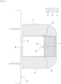
- feeder automatic exchange robot 26 is provided with periphery monitoring device 80 that monitors three directions around feeder automatic exchange robot 26.
- periphery monitoring device 80 monitoring areas A, B, and C (refer to Figs. 3 and 4 ) are set in three directions around feeder automatic exchange robot 26, and safety laser scanners 81, 82, and 83 are mounted for monitoring areas A, B, and C, respectively.
- Each of safety laser scanners 81, 82, and 83 is a safety sensor that changes an irradiating angle of the laser light with which monitoring areas A, B, and C are irradiated, scans an inside of each of monitoring areas A, B, and C with the laser light, and receives the laser light reflected upon hitting the detection target to detect a detection target that has intruded into each of monitoring areas A, B, and C.
- a width and a shape of each of monitoring areas A, B, and C, which is a detection area of each of safety laser scanners 81, 82, and 83, can be arbitrarily changed by a user.
- a safety distance which is a horizontal distance from a danger source (portion where feeder 14 is inserted and removed) on the front surface of component mounter 12, may be calculated by the following equation, and the inclination angle of three-dimensional monitoring area A may be determined such that the horizontal distance from the danger source to three-dimensional monitoring area A is equal to the safety distance.
- Safety distance Vmax ⁇ T1 + S1 + ⁇ S + Vman ⁇ T2 + S2
- Vmax is a maximum speed of feeder automatic exchange robot 26
- T1 is a time from the time when an object enters the danger area to the time when feeder automatic exchange robot 26 starts to apply the brake
- S1 is a braking distance of feeder automatic exchange robot 26
- ⁇ S is a measurement error of safety laser scanner 81
- Vman is an intrusion speed of a person
- T2 is a time from the time when the object enters the danger area to the time when feeder automatic exchange robot 26 stops
- S2 is a distance when a part of the body approaches the danger area before the person intrudes the danger area.
- monitoring areas B and C regions indicated by left hatched lines and right hatched lines in Fig. 4 ) for monitoring the right-left direction, which is the movement direction (X-direction and the opposite direction thereto) of feeder automatic exchange robot 26, are horizontal monitoring areas B and C for two-dimensionally monitoring in the horizontal direction.
- Safety laser scanners 82 and 83 for monitoring horizontal monitoring areas B and C in the right-left direction are mounted to the lower portion of feeder automatic exchange robot 26, so that horizontal monitoring areas B and C in the right-left direction are configured to form a horizontal plane-like monitoring area along floor surface 27 from the lower portion of feeder automatic exchange robot 26.
- Monitoring areas A, B, and C in individual directions are areas for cutting off a power source that is a power source of a driving system of feeder automatic exchange robot 26 in order to avoid collision between a person or an object intruding the area and feeder automatic exchange robot 26, thereby stopping feeder automatic exchange robot 26 in an emergency manner.
- a power source that is a power source of a driving system of feeder automatic exchange robot 26 in order to avoid collision between a person or an object intruding the area and feeder automatic exchange robot 26, thereby stopping feeder automatic exchange robot 26 in an emergency manner.
- a control power source that is a power source of the control system of periphery monitoring device 80 and feeder automatic exchange robot 26 is maintained, so that periphery monitoring device 80 monitors the presence or absence of the intrusion of the person or the object into monitoring areas A, B, and C in individual directions, and when the person or the object that has intruded into monitoring areas A, B, and C comes out of monitoring areas A, B, and C, the power source of feeder automatic exchange robot 26 is immediately restored to restart the movement control of feeder automatic exchange robot 26.
- monitoring areas A, B, and C are set in three directions around feeder automatic exchange robot 26.
- Monitoring area A for monitoring the front of feeder automatic exchange robot 26 in a direction different from the movement direction (X-direction and the opposite direction thereto) of feeder automatic exchange robot 26 is three-dimensional monitoring area A for three-dimensionally monitoring.
- Three-dimensional monitoring area A is configured to form the inclined plane-like monitoring area in which the interval from the front surface of feeder automatic exchange robot 26 gradually increases from the upper portion to the lower portion of feeder automatic exchange robot 26. Therefore, it is possible to detect a flying object, a rod-shaped object, or the like intruding the front surface of feeder automatic exchange robot 26, so that safety can be secured against the flying object, the rod-shaped object, or the like.
- three-dimensional monitoring area A since the detection can be performed as long as the fingertip of the operator approaches the front side of feeder automatic exchange robot 26, it is not necessary to set the horizontal distance of three-dimensional monitoring area A to be large in consideration of the range in which the fingertip of the operator extends. Therefore, it is possible to make the horizontal distance of three-dimensional monitoring area A be shorter than the horizontal distance of the conventional monitoring area. Therefore, it is possible to reduce the frequency at which the operator inadvertently intrudes three-dimensional monitoring area A and is detected compared to the conventional art, to reduce the frequency at which the operation of feeder automatic exchange robot 26 is stopped in an emergency manner, and also to secure productivity. In addition, it is possible to reduce the area where the work area in which the operator can safely work is narrowed by three-dimensional monitoring area A as compared with the conventional art, so that the efficiency can be secured.
- monitoring areas B and C for monitoring the movement direction (X-direction and the opposite direction thereto) of feeder automatic exchange robot 26 are horizontal monitoring areas B and C for two-dimensionally monitoring the horizontal direction from the lower portion of feeder automatic exchange robot 26.
- a part of horizontal monitoring areas B and C in the right-left direction is configured to cover the entire gap between the lower portion of three-dimensional monitoring area A and the lower portion of the front surface of feeder automatic exchange robot 26, it is sufficient if a part of horizontal monitoring areas B and C in the right-left direction protrudes to a position overlapping the lower portion of three-dimensional monitoring area A, and there may be some gap between horizontal monitoring areas B and C in the right-left direction inside three-dimensional monitoring area A. Even with this configuration, it is possible to obtain substantially the same advantages as those in the present embodiment.
- the present embodiment is an embodiment in which the present invention is applied to feeder automatic exchange robot 26, it may be applied to various types of moving bodies such as an autonomous running robot or an unmanned conveyance vehicle other than feeder automatic exchange robot 26.
- the monitoring area may be set in four directions of the moving body, or the monitoring area in two directions in the movement direction of the moving body or the orthogonal direction may be set as the three-dimensional monitoring area, and the monitoring area in the other two directions may be set as the horizontal monitoring area.
- whether the monitoring area in each direction around the moving body is to be the three-dimensional monitoring area or the horizontal monitoring area may be determined, for example, in consideration of the type of the moving body, a positional relationship between a traveling path of the moving body and the work area, the movement direction of the moving body, and the like.
Landscapes
- Engineering & Computer Science (AREA)
- Manufacturing & Machinery (AREA)
- Microelectronics & Electronic Packaging (AREA)
- Robotics (AREA)
- Mechanical Engineering (AREA)
- Operations Research (AREA)
- Human Computer Interaction (AREA)
- Manipulator (AREA)
- Supply And Installment Of Electrical Components (AREA)
Claims (6)
- Eine Peripherieüberwachungsvorrichtung (80), die konfiguriert ist, Licht in Überwachungsbereiche in mindestens drei Richtungen eines sich bewegenden Körpers (26) zu emittieren, wobei die Peripherieüberwachungsvorrichtung (80) den sich bewegenden Körper (26) und einen ersten und zweiten Sicherheitslaserscanner umfasst, wobeider erste und der zweite Sicherheitslaserscanner (81, 82, 83) für jeden der Überwachungsbereiche in den Richtungen an dem beweglichen Körper (26) angebracht sind,dadurch gekennzeichnet, dassein Überwachungsbereich (A) in mindestens einer Richtung ein dreidimensionaler Überwachungsbereich (A) ist, der dreidimensional zu überwachen ist, und ein Überwachungsbereich (B, C) in der anderen Richtung ein horizontaler Überwachungsbereich (B, C) ist, der zweidimensional in einer horizontalen Richtung zu überwachen ist,der erste Sicherheitslaserscanner (81), der konfiguriert ist, den dreidimensionalen Überwachungsbereich (A) zu überwachen, an einem oberen Abschnitt des sich bewegenden Körpers (26) angebracht ist, wobei der dreidimensionale Überwachungsbereich (A) einen schiefen, ebenenartigen Überwachungsbereich (A) bildet, in dem ein Abstand von dem sich bewegenden Körper (26) allmählich von dem oberen Abschnitt zu einem unteren Abschnitt des sich bewegenden Körpers (26) zunimmt, undder zweite Sicherheitslaserscanner (82, 83), der zum Überwachen des horizontalen Überwachungsbereichs (B, C) konfiguriert ist, an dem unteren Abschnitt des sich bewegenden Körpers (26) angebracht ist, wobei der horizontale Überwachungsbereich (8, C) einen horizontalen ebenenartigen Überwachungsbereich (B, C) von dem unteren Abschnitt des sich bewegenden Körpers (26) bildet.
- Die Peripherieüberwachungsvorrichtung (80) gemäß Anspruch 1, wobei
der dreidimensionale Überwachungsbereich (A) so eingestellt ist, dass er eine Richtung dreidimensional überwacht, die sich von einer Bewegungsrichtung des beweglichen Körpers (26) unterscheidet. - Die Peripherieüberwachungsvorrichtung (80) gemäß Anspruch 1 oder 2, wobeihorizontale Überwachungsbereiche (8, C) auf beiden Seiten des dreidimensionalen Überwachungsbereichs (A) angeordnet sind, undein Teil der horizontalen Überwachungsbereiche (B, C) bis zu einer Position vorsteht, die einen unteren Abschnitt des dreidimensionalen Überwachungsbereichs (A) überlappt.
- Die Peripherieüberwachungsvorrichtung (80) gemäß Anspruch 3, wobeider Sicherheitslaserscanner (82, 83), der zum Überwachen des horizontalen Überwachungsbereichs (B, C) konfiguriert ist, an einem Eckabschnitt des unteren Abschnitts des beweglichen Körpers (26) auf einer Seite des dreidimensionalen Überwachungsbereichs angebracht ist, undein Teil der horizontalen Überwachungsbereiche (B, C), die auf beiden Seiten der dreidimensionalen Überwachungsbereiche (A) angeordnet sind, vorsteht, um einen gesamten Spalt zwischen dem unteren Abschnitt des dreidimensionalen Überwachungsbereichs (A) und dem unteren Abschnitt des beweglichen Körpers (26) abzudecken.
- Die Peripherieüberwachungsvorrichtung (80) gemäß einem der Ansprüche 1 bis 4, wobei der bewegliche Körper (26) ein autonomer Laufroboter (26) ist.
- Die Peripherieüberwachungsvorrichtung (80) gemäß Anspruch 5, wobei
der autonome Laufroboter (26) ein automatischer Zuführwechselroboter (26) ist, der sich entlang einer Anordnung von mehreren Komponentenmontierern (12) bewegt, die eine Komponentenmontagelinie (10) bilden, um automatisch eine Zuführung zwischen dem automatischen Zuführwechselroboter (26) und jedem Komponentenmontierer (12) auszutauschen.
Applications Claiming Priority (1)
| Application Number | Priority Date | Filing Date | Title |
|---|---|---|---|
| PCT/JP2019/037151 WO2021059317A1 (ja) | 2019-09-23 | 2019-09-23 | 周辺監視装置 |
Publications (3)
| Publication Number | Publication Date |
|---|---|
| EP4037447A1 EP4037447A1 (de) | 2022-08-03 |
| EP4037447A4 EP4037447A4 (de) | 2022-09-21 |
| EP4037447B1 true EP4037447B1 (de) | 2024-08-07 |
Family
ID=75165190
Family Applications (1)
| Application Number | Title | Priority Date | Filing Date |
|---|---|---|---|
| EP19946278.9A Active EP4037447B1 (de) | 2019-09-23 | 2019-09-23 | Peripherieüberwachungsvorrichtung |
Country Status (5)
| Country | Link |
|---|---|
| US (1) | US12120825B2 (de) |
| EP (1) | EP4037447B1 (de) |
| JP (1) | JP7194288B2 (de) |
| CN (1) | CN114271042B (de) |
| WO (1) | WO2021059317A1 (de) |
Family Cites Families (32)
| Publication number | Priority date | Publication date | Assignee | Title |
|---|---|---|---|---|
| DE3423536C2 (de) * | 1984-06-26 | 1986-09-11 | Erwin Sick Gmbh Optik-Elektronik, 7808 Waldkirch | Lichtelektrische Schutzzonenvorrichtung an einem Fahrzeug |
| JPH01222889A (ja) * | 1988-02-26 | 1989-09-06 | Murata Mach Ltd | 自走式ロボットの安全装置 |
| JPH1188870A (ja) * | 1997-09-05 | 1999-03-30 | Tokai Rika Co Ltd | 監視システム |
| JP4006577B2 (ja) * | 2002-03-13 | 2007-11-14 | オムロン株式会社 | 監視装置 |
| JP3704706B2 (ja) * | 2002-03-13 | 2005-10-12 | オムロン株式会社 | 三次元監視装置 |
| JP3948381B2 (ja) * | 2002-09-30 | 2007-07-25 | 石川島播磨重工業株式会社 | 直方体計測方法及び直方体計測装置 |
| US20120123563A1 (en) * | 2010-11-17 | 2012-05-17 | Omron Scientific Technologies, Inc. | Method and Apparatus for Monitoring Zones |
| DE112011104645T5 (de) * | 2010-12-30 | 2013-10-10 | Irobot Corp. | Mobiler Mensch-Schnittstellen-Roboter |
| JP5906878B2 (ja) * | 2012-03-27 | 2016-04-20 | 富士ゼロックス株式会社 | 電力供給制御装置、画像処理装置、電力供給制御プログラム |
| JP2015170284A (ja) * | 2014-03-10 | 2015-09-28 | 株式会社日立製作所 | フォークリフト型無人搬送車、その制御方法および制御装置 |
| DE202014105727U1 (de) * | 2014-11-27 | 2016-03-01 | Sick Ag | Sensorsystem |
| JP6034892B2 (ja) * | 2015-01-27 | 2016-11-30 | ファナック株式会社 | ロボットの設置台の輝度が変化するロボットシステム |
| CN107430405B (zh) * | 2015-03-23 | 2020-10-02 | 株式会社富士 | 移动体 |
| WO2017116585A1 (en) * | 2015-12-30 | 2017-07-06 | Faro Technologies, Inc. | Registration of three-dimensional coordinates measured on interior and exterior portions of an object |
| JP2017122634A (ja) * | 2016-01-07 | 2017-07-13 | シャープ株式会社 | 検知装置および移動体 |
| JP6762097B2 (ja) * | 2016-01-22 | 2020-09-30 | 株式会社Fuji | フィーダ自動交換システム |
| US10945361B2 (en) * | 2016-02-17 | 2021-03-09 | Fuji Corporation | Production line safety system |
| JP6780901B2 (ja) * | 2016-08-26 | 2020-11-04 | 株式会社Fuji | 移動体 |
| CN206536514U (zh) * | 2017-01-16 | 2017-10-03 | 山东华力机电有限公司 | 搬运机器人安全保护装置 |
| US12287628B2 (en) * | 2017-01-20 | 2025-04-29 | Follow Inspiration, S.A. | Method and system to improve autonomous robotic systems responsive behavior |
| JP6490121B2 (ja) * | 2017-02-17 | 2019-03-27 | ファナック株式会社 | ロボットシステム |
| US10545222B2 (en) * | 2017-05-08 | 2020-01-28 | Velodyne Lidar, Inc. | LIDAR data acquisition and control |
| JP6416980B1 (ja) * | 2017-05-17 | 2018-10-31 | ファナック株式会社 | 監視領域を分割した空間領域を監視する監視装置 |
| JP2019010704A (ja) * | 2017-06-30 | 2019-01-24 | Idec株式会社 | 照光表示装置 |
| JP7179051B2 (ja) * | 2017-08-28 | 2022-11-28 | トリナミクス ゲゼルシャフト ミット ベシュレンクテル ハフツング | 少なくとも1つの物体の位置を決定するための検出器 |
| US11125860B2 (en) * | 2017-09-29 | 2021-09-21 | Rockwell Automation Technologies, Inc. | Triangulation applied as a safety scanner |
| WO2019087392A1 (ja) | 2017-11-06 | 2019-05-09 | 株式会社Fuji | 部品実装ライン |
| US10394234B2 (en) * | 2017-12-18 | 2019-08-27 | The Boeing Company | Multi-sensor safe path system for autonomous vehicles |
| JP7052343B2 (ja) * | 2017-12-26 | 2022-04-12 | トヨタ自動車株式会社 | 自律移動体および情報収集システム |
| US10712434B2 (en) * | 2018-09-18 | 2020-07-14 | Velodyne Lidar, Inc. | Multi-channel LIDAR illumination driver |
| GB2584914A (en) * | 2019-06-28 | 2020-12-23 | Airbus Operations Ltd | Autonomous mobile aircraft inspection system |
| WO2021053832A1 (ja) | 2019-09-20 | 2021-03-25 | 株式会社Fuji | 生産ラインの自動交換システム |
-
2019
- 2019-09-23 EP EP19946278.9A patent/EP4037447B1/de active Active
- 2019-09-23 US US17/635,618 patent/US12120825B2/en active Active
- 2019-09-23 JP JP2021547991A patent/JP7194288B2/ja active Active
- 2019-09-23 WO PCT/JP2019/037151 patent/WO2021059317A1/ja not_active Ceased
- 2019-09-23 CN CN201980099645.6A patent/CN114271042B/zh active Active
Also Published As
| Publication number | Publication date |
|---|---|
| WO2021059317A1 (ja) | 2021-04-01 |
| CN114271042B (zh) | 2024-03-08 |
| JP7194288B2 (ja) | 2022-12-21 |
| CN114271042A (zh) | 2022-04-01 |
| US12120825B2 (en) | 2024-10-15 |
| EP4037447A4 (de) | 2022-09-21 |
| EP4037447A1 (de) | 2022-08-03 |
| JPWO2021059317A1 (de) | 2021-04-01 |
| US20220295680A1 (en) | 2022-09-15 |
Similar Documents
| Publication | Publication Date | Title |
|---|---|---|
| EP3276442B1 (de) | Beweglicher körper | |
| JP6831925B2 (ja) | 部品実装ライン | |
| EP3657282B1 (de) | Arbeitssystem | |
| EP3764763B1 (de) | Komponentenmontagesystem | |
| JP2008311516A (ja) | 実装機およびフィーダ異常検出装置 | |
| US11943870B2 (en) | Component mounting line | |
| EP4135501B1 (de) | Produktionsanlage | |
| EP4037447B1 (de) | Peripherieüberwachungsvorrichtung | |
| EP4037451B1 (de) | Automatisiertes ersatzsystem für produktionslinie | |
| JP2025168490A (ja) | 作業装置 | |
| US20250296782A1 (en) | Article conveyance system and article conveyance method | |
| US20210094136A1 (en) | Detection system for detecting workpiece | |
| JP7700252B2 (ja) | 作業装置および実装システム | |
| JP6964742B2 (ja) | 作業システム | |
| JP2025169280A (ja) | オペレータ検出システム |
Legal Events
| Date | Code | Title | Description |
|---|---|---|---|
| STAA | Information on the status of an ep patent application or granted ep patent |
Free format text: STATUS: THE INTERNATIONAL PUBLICATION HAS BEEN MADE |
|
| PUAI | Public reference made under article 153(3) epc to a published international application that has entered the european phase |
Free format text: ORIGINAL CODE: 0009012 |
|
| STAA | Information on the status of an ep patent application or granted ep patent |
Free format text: STATUS: REQUEST FOR EXAMINATION WAS MADE |
|
| 17P | Request for examination filed |
Effective date: 20220210 |
|
| AK | Designated contracting states |
Kind code of ref document: A1 Designated state(s): AL AT BE BG CH CY CZ DE DK EE ES FI FR GB GR HR HU IE IS IT LI LT LU LV MC MK MT NL NO PL PT RO RS SE SI SK SM TR |
|
| A4 | Supplementary search report drawn up and despatched |
Effective date: 20220824 |
|
| RIC1 | Information provided on ipc code assigned before grant |
Ipc: H05K 13/08 20060101ALI20220818BHEP Ipc: H05K 13/02 20060101ALI20220818BHEP Ipc: H05K 13/00 20060101AFI20220818BHEP |
|
| DAV | Request for validation of the european patent (deleted) | ||
| DAX | Request for extension of the european patent (deleted) | ||
| P01 | Opt-out of the competence of the unified patent court (upc) registered |
Effective date: 20230328 |
|
| GRAP | Despatch of communication of intention to grant a patent |
Free format text: ORIGINAL CODE: EPIDOSNIGR1 |
|
| STAA | Information on the status of an ep patent application or granted ep patent |
Free format text: STATUS: GRANT OF PATENT IS INTENDED |
|
| INTG | Intention to grant announced |
Effective date: 20240502 |
|
| GRAS | Grant fee paid |
Free format text: ORIGINAL CODE: EPIDOSNIGR3 |
|
| GRAA | (expected) grant |
Free format text: ORIGINAL CODE: 0009210 |
|
| STAA | Information on the status of an ep patent application or granted ep patent |
Free format text: STATUS: THE PATENT HAS BEEN GRANTED |
|
| AK | Designated contracting states |
Kind code of ref document: B1 Designated state(s): AL AT BE BG CH CY CZ DE DK EE ES FI FR GB GR HR HU IE IS IT LI LT LU LV MC MK MT NL NO PL PT RO RS SE SI SK SM TR |
|
| REG | Reference to a national code |
Ref country code: GB Ref legal event code: FG4D |
|
| REG | Reference to a national code |
Ref country code: CH Ref legal event code: EP |
|
| REG | Reference to a national code |
Ref country code: IE Ref legal event code: FG4D |
|
| REG | Reference to a national code |
Ref country code: DE Ref legal event code: R096 Ref document number: 602019056842 Country of ref document: DE |
|
| REG | Reference to a national code |
Ref country code: LT Ref legal event code: MG9D |
|
| REG | Reference to a national code |
Ref country code: NL Ref legal event code: MP Effective date: 20240807 |
|
| PG25 | Lapsed in a contracting state [announced via postgrant information from national office to epo] |
Ref country code: NO Free format text: LAPSE BECAUSE OF FAILURE TO SUBMIT A TRANSLATION OF THE DESCRIPTION OR TO PAY THE FEE WITHIN THE PRESCRIBED TIME-LIMIT Effective date: 20241107 |
|
| REG | Reference to a national code |
Ref country code: AT Ref legal event code: MK05 Ref document number: 1712327 Country of ref document: AT Kind code of ref document: T Effective date: 20240807 |
|
| PG25 | Lapsed in a contracting state [announced via postgrant information from national office to epo] |
Ref country code: PT Free format text: LAPSE BECAUSE OF FAILURE TO SUBMIT A TRANSLATION OF THE DESCRIPTION OR TO PAY THE FEE WITHIN THE PRESCRIBED TIME-LIMIT Effective date: 20241209 Ref country code: NL Free format text: LAPSE BECAUSE OF FAILURE TO SUBMIT A TRANSLATION OF THE DESCRIPTION OR TO PAY THE FEE WITHIN THE PRESCRIBED TIME-LIMIT Effective date: 20240807 Ref country code: FI Free format text: LAPSE BECAUSE OF FAILURE TO SUBMIT A TRANSLATION OF THE DESCRIPTION OR TO PAY THE FEE WITHIN THE PRESCRIBED TIME-LIMIT Effective date: 20240807 Ref country code: PL Free format text: LAPSE BECAUSE OF FAILURE TO SUBMIT A TRANSLATION OF THE DESCRIPTION OR TO PAY THE FEE WITHIN THE PRESCRIBED TIME-LIMIT Effective date: 20240807 Ref country code: GR Free format text: LAPSE BECAUSE OF FAILURE TO SUBMIT A TRANSLATION OF THE DESCRIPTION OR TO PAY THE FEE WITHIN THE PRESCRIBED TIME-LIMIT Effective date: 20241108 |
|
| PG25 | Lapsed in a contracting state [announced via postgrant information from national office to epo] |
Ref country code: BG Free format text: LAPSE BECAUSE OF FAILURE TO SUBMIT A TRANSLATION OF THE DESCRIPTION OR TO PAY THE FEE WITHIN THE PRESCRIBED TIME-LIMIT Effective date: 20240807 |
|
| PG25 | Lapsed in a contracting state [announced via postgrant information from national office to epo] |
Ref country code: LV Free format text: LAPSE BECAUSE OF FAILURE TO SUBMIT A TRANSLATION OF THE DESCRIPTION OR TO PAY THE FEE WITHIN THE PRESCRIBED TIME-LIMIT Effective date: 20240807 |
|
| PG25 | Lapsed in a contracting state [announced via postgrant information from national office to epo] |
Ref country code: AT Free format text: LAPSE BECAUSE OF FAILURE TO SUBMIT A TRANSLATION OF THE DESCRIPTION OR TO PAY THE FEE WITHIN THE PRESCRIBED TIME-LIMIT Effective date: 20240807 Ref country code: IS Free format text: LAPSE BECAUSE OF FAILURE TO SUBMIT A TRANSLATION OF THE DESCRIPTION OR TO PAY THE FEE WITHIN THE PRESCRIBED TIME-LIMIT Effective date: 20241207 |
|
| PG25 | Lapsed in a contracting state [announced via postgrant information from national office to epo] |
Ref country code: HR Free format text: LAPSE BECAUSE OF FAILURE TO SUBMIT A TRANSLATION OF THE DESCRIPTION OR TO PAY THE FEE WITHIN THE PRESCRIBED TIME-LIMIT Effective date: 20240807 |
|
| PG25 | Lapsed in a contracting state [announced via postgrant information from national office to epo] |
Ref country code: ES Free format text: LAPSE BECAUSE OF FAILURE TO SUBMIT A TRANSLATION OF THE DESCRIPTION OR TO PAY THE FEE WITHIN THE PRESCRIBED TIME-LIMIT Effective date: 20240807 Ref country code: RS Free format text: LAPSE BECAUSE OF FAILURE TO SUBMIT A TRANSLATION OF THE DESCRIPTION OR TO PAY THE FEE WITHIN THE PRESCRIBED TIME-LIMIT Effective date: 20241107 |
|
| PG25 | Lapsed in a contracting state [announced via postgrant information from national office to epo] |
Ref country code: RS Free format text: LAPSE BECAUSE OF FAILURE TO SUBMIT A TRANSLATION OF THE DESCRIPTION OR TO PAY THE FEE WITHIN THE PRESCRIBED TIME-LIMIT Effective date: 20241107 Ref country code: PT Free format text: LAPSE BECAUSE OF FAILURE TO SUBMIT A TRANSLATION OF THE DESCRIPTION OR TO PAY THE FEE WITHIN THE PRESCRIBED TIME-LIMIT Effective date: 20241209 Ref country code: PL Free format text: LAPSE BECAUSE OF FAILURE TO SUBMIT A TRANSLATION OF THE DESCRIPTION OR TO PAY THE FEE WITHIN THE PRESCRIBED TIME-LIMIT Effective date: 20240807 Ref country code: NO Free format text: LAPSE BECAUSE OF FAILURE TO SUBMIT A TRANSLATION OF THE DESCRIPTION OR TO PAY THE FEE WITHIN THE PRESCRIBED TIME-LIMIT Effective date: 20241107 Ref country code: NL Free format text: LAPSE BECAUSE OF FAILURE TO SUBMIT A TRANSLATION OF THE DESCRIPTION OR TO PAY THE FEE WITHIN THE PRESCRIBED TIME-LIMIT Effective date: 20240807 Ref country code: LV Free format text: LAPSE BECAUSE OF FAILURE TO SUBMIT A TRANSLATION OF THE DESCRIPTION OR TO PAY THE FEE WITHIN THE PRESCRIBED TIME-LIMIT Effective date: 20240807 Ref country code: IS Free format text: LAPSE BECAUSE OF FAILURE TO SUBMIT A TRANSLATION OF THE DESCRIPTION OR TO PAY THE FEE WITHIN THE PRESCRIBED TIME-LIMIT Effective date: 20241207 Ref country code: HR Free format text: LAPSE BECAUSE OF FAILURE TO SUBMIT A TRANSLATION OF THE DESCRIPTION OR TO PAY THE FEE WITHIN THE PRESCRIBED TIME-LIMIT Effective date: 20240807 Ref country code: GR Free format text: LAPSE BECAUSE OF FAILURE TO SUBMIT A TRANSLATION OF THE DESCRIPTION OR TO PAY THE FEE WITHIN THE PRESCRIBED TIME-LIMIT Effective date: 20241108 Ref country code: FI Free format text: LAPSE BECAUSE OF FAILURE TO SUBMIT A TRANSLATION OF THE DESCRIPTION OR TO PAY THE FEE WITHIN THE PRESCRIBED TIME-LIMIT Effective date: 20240807 Ref country code: ES Free format text: LAPSE BECAUSE OF FAILURE TO SUBMIT A TRANSLATION OF THE DESCRIPTION OR TO PAY THE FEE WITHIN THE PRESCRIBED TIME-LIMIT Effective date: 20240807 Ref country code: BG Free format text: LAPSE BECAUSE OF FAILURE TO SUBMIT A TRANSLATION OF THE DESCRIPTION OR TO PAY THE FEE WITHIN THE PRESCRIBED TIME-LIMIT Effective date: 20240807 Ref country code: AT Free format text: LAPSE BECAUSE OF FAILURE TO SUBMIT A TRANSLATION OF THE DESCRIPTION OR TO PAY THE FEE WITHIN THE PRESCRIBED TIME-LIMIT Effective date: 20240807 |
|
| PG25 | Lapsed in a contracting state [announced via postgrant information from national office to epo] |
Ref country code: SM Free format text: LAPSE BECAUSE OF FAILURE TO SUBMIT A TRANSLATION OF THE DESCRIPTION OR TO PAY THE FEE WITHIN THE PRESCRIBED TIME-LIMIT Effective date: 20240807 Ref country code: DK Free format text: LAPSE BECAUSE OF FAILURE TO SUBMIT A TRANSLATION OF THE DESCRIPTION OR TO PAY THE FEE WITHIN THE PRESCRIBED TIME-LIMIT Effective date: 20240807 |
|
| PG25 | Lapsed in a contracting state [announced via postgrant information from national office to epo] |
Ref country code: EE Free format text: LAPSE BECAUSE OF FAILURE TO SUBMIT A TRANSLATION OF THE DESCRIPTION OR TO PAY THE FEE WITHIN THE PRESCRIBED TIME-LIMIT Effective date: 20240807 |
|
| PG25 | Lapsed in a contracting state [announced via postgrant information from national office to epo] |
Ref country code: CZ Free format text: LAPSE BECAUSE OF FAILURE TO SUBMIT A TRANSLATION OF THE DESCRIPTION OR TO PAY THE FEE WITHIN THE PRESCRIBED TIME-LIMIT Effective date: 20240807 |
|
| PG25 | Lapsed in a contracting state [announced via postgrant information from national office to epo] |
Ref country code: SK Free format text: LAPSE BECAUSE OF FAILURE TO SUBMIT A TRANSLATION OF THE DESCRIPTION OR TO PAY THE FEE WITHIN THE PRESCRIBED TIME-LIMIT Effective date: 20240807 |
|
| REG | Reference to a national code |
Ref country code: CH Ref legal event code: PL |
|
| REG | Reference to a national code |
Ref country code: DE Ref legal event code: R097 Ref document number: 602019056842 Country of ref document: DE |
|
| PG25 | Lapsed in a contracting state [announced via postgrant information from national office to epo] |
Ref country code: LU Free format text: LAPSE BECAUSE OF NON-PAYMENT OF DUE FEES Effective date: 20240923 |
|
| PLBE | No opposition filed within time limit |
Free format text: ORIGINAL CODE: 0009261 |
|
| STAA | Information on the status of an ep patent application or granted ep patent |
Free format text: STATUS: NO OPPOSITION FILED WITHIN TIME LIMIT |
|
| PG25 | Lapsed in a contracting state [announced via postgrant information from national office to epo] |
Ref country code: MC Free format text: LAPSE BECAUSE OF FAILURE TO SUBMIT A TRANSLATION OF THE DESCRIPTION OR TO PAY THE FEE WITHIN THE PRESCRIBED TIME-LIMIT Effective date: 20240807 |
|
| REG | Reference to a national code |
Ref country code: BE Ref legal event code: MM Effective date: 20240930 |
|
| PG25 | Lapsed in a contracting state [announced via postgrant information from national office to epo] |
Ref country code: BE Free format text: LAPSE BECAUSE OF NON-PAYMENT OF DUE FEES Effective date: 20240930 |
|
| 26N | No opposition filed |
Effective date: 20250508 |
|
| PG25 | Lapsed in a contracting state [announced via postgrant information from national office to epo] |
Ref country code: FR Free format text: LAPSE BECAUSE OF NON-PAYMENT OF DUE FEES Effective date: 20241007 |
|
| GBPC | Gb: european patent ceased through non-payment of renewal fee |
Effective date: 20241107 |
|
| PG25 | Lapsed in a contracting state [announced via postgrant information from national office to epo] |
Ref country code: CH Free format text: LAPSE BECAUSE OF NON-PAYMENT OF DUE FEES Effective date: 20240930 |
|
| PG25 | Lapsed in a contracting state [announced via postgrant information from national office to epo] |
Ref country code: IE Free format text: LAPSE BECAUSE OF NON-PAYMENT OF DUE FEES Effective date: 20240923 |
|
| PG25 | Lapsed in a contracting state [announced via postgrant information from national office to epo] |
Ref country code: SE Free format text: LAPSE BECAUSE OF FAILURE TO SUBMIT A TRANSLATION OF THE DESCRIPTION OR TO PAY THE FEE WITHIN THE PRESCRIBED TIME-LIMIT Effective date: 20240807 |
|
| PGFP | Annual fee paid to national office [announced via postgrant information from national office to epo] |
Ref country code: DE Payment date: 20250730 Year of fee payment: 7 |
|
| PG25 | Lapsed in a contracting state [announced via postgrant information from national office to epo] |
Ref country code: GB Free format text: LAPSE BECAUSE OF NON-PAYMENT OF DUE FEES Effective date: 20241107 |
|
| PG25 | Lapsed in a contracting state [announced via postgrant information from national office to epo] |
Ref country code: RO Free format text: LAPSE BECAUSE OF FAILURE TO SUBMIT A TRANSLATION OF THE DESCRIPTION OR TO PAY THE FEE WITHIN THE PRESCRIBED TIME-LIMIT Effective date: 20240807 |
|
| PG25 | Lapsed in a contracting state [announced via postgrant information from national office to epo] |
Ref country code: CY Free format text: LAPSE BECAUSE OF FAILURE TO SUBMIT A TRANSLATION OF THE DESCRIPTION OR TO PAY THE FEE WITHIN THE PRESCRIBED TIME-LIMIT; INVALID AB INITIO Effective date: 20190923 Ref country code: IT Free format text: LAPSE BECAUSE OF FAILURE TO SUBMIT A TRANSLATION OF THE DESCRIPTION OR TO PAY THE FEE WITHIN THE PRESCRIBED TIME-LIMIT Effective date: 20240807 |