EP4037105A1 - Leiteranschlussklemme, prüfanordnung und prüfverfahren - Google Patents
Leiteranschlussklemme, prüfanordnung und prüfverfahren Download PDFInfo
- Publication number
- EP4037105A1 EP4037105A1 EP22153970.3A EP22153970A EP4037105A1 EP 4037105 A1 EP4037105 A1 EP 4037105A1 EP 22153970 A EP22153970 A EP 22153970A EP 4037105 A1 EP4037105 A1 EP 4037105A1
- Authority
- EP
- European Patent Office
- Prior art keywords
- housing
- conductor
- light
- connection terminal
- spring
- Prior art date
- Legal status (The legal status is an assumption and is not a legal conclusion. Google has not performed a legal analysis and makes no representation as to the accuracy of the status listed.)
- Granted
Links
Images

Classifications
-
- H—ELECTRICITY
- H01—ELECTRIC ELEMENTS
- H01R—ELECTRICALLY-CONDUCTIVE CONNECTIONS; STRUCTURAL ASSOCIATIONS OF A PLURALITY OF MUTUALLY-INSULATED ELECTRICAL CONNECTING ELEMENTS; COUPLING DEVICES; CURRENT COLLECTORS
- H01R4/00—Electrically-conductive connections between two or more conductive members in direct contact, i.e. touching one another; Means for effecting or maintaining such contact; Electrically-conductive connections having two or more spaced connecting locations for conductors and using contact members penetrating insulation
- H01R4/28—Clamped connections, spring connections
- H01R4/48—Clamped connections, spring connections utilising a spring, clip, or other resilient member
-
- G—PHYSICS
- G01—MEASURING; TESTING
- G01M—TESTING STATIC OR DYNAMIC BALANCE OF MACHINES OR STRUCTURES; TESTING OF STRUCTURES OR APPARATUS, NOT OTHERWISE PROVIDED FOR
- G01M11/00—Testing of optical apparatus; Testing structures by optical methods not otherwise provided for
- G01M11/02—Testing optical properties
-
- G—PHYSICS
- G02—OPTICS
- G02B—OPTICAL ELEMENTS, SYSTEMS OR APPARATUS
- G02B6/00—Light guides; Structural details of arrangements comprising light guides and other optical elements, e.g. couplings
- G02B6/0001—Light guides; Structural details of arrangements comprising light guides and other optical elements, e.g. couplings specially adapted for lighting devices or systems
-
- H—ELECTRICITY
- H01—ELECTRIC ELEMENTS
- H01R—ELECTRICALLY-CONDUCTIVE CONNECTIONS; STRUCTURAL ASSOCIATIONS OF A PLURALITY OF MUTUALLY-INSULATED ELECTRICAL CONNECTING ELEMENTS; COUPLING DEVICES; CURRENT COLLECTORS
- H01R4/00—Electrically-conductive connections between two or more conductive members in direct contact, i.e. touching one another; Means for effecting or maintaining such contact; Electrically-conductive connections having two or more spaced connecting locations for conductors and using contact members penetrating insulation
- H01R4/28—Clamped connections, spring connections
- H01R4/48—Clamped connections, spring connections utilising a spring, clip, or other resilient member
- H01R4/4809—Clamped connections, spring connections utilising a spring, clip, or other resilient member using a leaf spring to bias the conductor toward the busbar
- H01R4/484—Spring housing details
-
- H—ELECTRICITY
- H01—ELECTRIC ELEMENTS
- H01R—ELECTRICALLY-CONDUCTIVE CONNECTIONS; STRUCTURAL ASSOCIATIONS OF A PLURALITY OF MUTUALLY-INSULATED ELECTRICAL CONNECTING ELEMENTS; COUPLING DEVICES; CURRENT COLLECTORS
- H01R13/00—Details of coupling devices of the kinds covered by groups H01R12/70 or H01R24/00 - H01R33/00
- H01R13/66—Structural association with built-in electrical component
- H01R13/717—Structural association with built-in electrical component with built-in light source
- H01R13/7172—Conduits for light transmission
-
- H—ELECTRICITY
- H01—ELECTRIC ELEMENTS
- H01R—ELECTRICALLY-CONDUCTIVE CONNECTIONS; STRUCTURAL ASSOCIATIONS OF A PLURALITY OF MUTUALLY-INSULATED ELECTRICAL CONNECTING ELEMENTS; COUPLING DEVICES; CURRENT COLLECTORS
- H01R2201/00—Connectors or connections adapted for particular applications
- H01R2201/20—Connectors or connections adapted for particular applications for testing or measuring purposes
-
- H—ELECTRICITY
- H01—ELECTRIC ELEMENTS
- H01R—ELECTRICALLY-CONDUCTIVE CONNECTIONS; STRUCTURAL ASSOCIATIONS OF A PLURALITY OF MUTUALLY-INSULATED ELECTRICAL CONNECTING ELEMENTS; COUPLING DEVICES; CURRENT COLLECTORS
- H01R4/00—Electrically-conductive connections between two or more conductive members in direct contact, i.e. touching one another; Means for effecting or maintaining such contact; Electrically-conductive connections having two or more spaced connecting locations for conductors and using contact members penetrating insulation
- H01R4/28—Clamped connections, spring connections
- H01R4/48—Clamped connections, spring connections utilising a spring, clip, or other resilient member
- H01R4/4809—Clamped connections, spring connections utilising a spring, clip, or other resilient member using a leaf spring to bias the conductor toward the busbar
- H01R4/48185—Clamped connections, spring connections utilising a spring, clip, or other resilient member using a leaf spring to bias the conductor toward the busbar adapted for axial insertion of a wire end
- H01R4/4819—Clamped connections, spring connections utilising a spring, clip, or other resilient member using a leaf spring to bias the conductor toward the busbar adapted for axial insertion of a wire end the spring shape allowing insertion of the conductor end when the spring is unbiased
- H01R4/4821—Single-blade spring
-
- H—ELECTRICITY
- H01—ELECTRIC ELEMENTS
- H01R—ELECTRICALLY-CONDUCTIVE CONNECTIONS; STRUCTURAL ASSOCIATIONS OF A PLURALITY OF MUTUALLY-INSULATED ELECTRICAL CONNECTING ELEMENTS; COUPLING DEVICES; CURRENT COLLECTORS
- H01R4/00—Electrically-conductive connections between two or more conductive members in direct contact, i.e. touching one another; Means for effecting or maintaining such contact; Electrically-conductive connections having two or more spaced connecting locations for conductors and using contact members penetrating insulation
- H01R4/28—Clamped connections, spring connections
- H01R4/48—Clamped connections, spring connections utilising a spring, clip, or other resilient member
- H01R4/4809—Clamped connections, spring connections utilising a spring, clip, or other resilient member using a leaf spring to bias the conductor toward the busbar
- H01R4/4828—Spring-activating arrangements mounted on or integrally formed with the spring housing
- H01R4/483—Pivoting arrangements, e.g. lever pushing on the spring
-
- H—ELECTRICITY
- H01—ELECTRIC ELEMENTS
- H01R—ELECTRICALLY-CONDUCTIVE CONNECTIONS; STRUCTURAL ASSOCIATIONS OF A PLURALITY OF MUTUALLY-INSULATED ELECTRICAL CONNECTING ELEMENTS; COUPLING DEVICES; CURRENT COLLECTORS
- H01R4/00—Electrically-conductive connections between two or more conductive members in direct contact, i.e. touching one another; Means for effecting or maintaining such contact; Electrically-conductive connections having two or more spaced connecting locations for conductors and using contact members penetrating insulation
- H01R4/28—Clamped connections, spring connections
- H01R4/48—Clamped connections, spring connections utilising a spring, clip, or other resilient member
- H01R4/4809—Clamped connections, spring connections utilising a spring, clip, or other resilient member using a leaf spring to bias the conductor toward the busbar
- H01R4/4846—Busbar details
- H01R4/485—Single busbar common to multiple springs
Definitions
- the invention relates to a conductor terminal with a housing and at least one spring-cage terminal arranged in the housing for clamping an electrical conductor by means of spring force, wherein at least a portion of the housing is formed from optically transparent material.
- the invention also relates to a test arrangement for testing the functionality of such a conductor terminal and a method for testing the functionality.
- Conductor connection terminals of the type mentioned are known, e.g. through the 221 series of the applicant. Such conductor connection terminals are sometimes offered with transparent housings, so that the correct insertion of an electrical conductor can be visually checked by the user.
- the invention is based on the object of specifying a conductor terminal with further improved testing options which, in particular, also allow the functional capability of the conductor terminal to be tested.
- the conductor connection terminal has at least one light-conducting element inside the housing, through which light radiated from the outside through the optically transparent partial area of the housing can be guided and/or guided into the housing to a predetermined position in the housing can be deflected into a predetermined emission direction in the housing, which is different from the direction of incidence of the light.
- the invention has the advantage that the conductor connection terminal enables improved and, in particular, simplified automatic testing by an optical testing arrangement.
- the at least one light guide element arranged in the housing, which makes it possible for light to shine into the housing from the outside through the optically transparent partial area of the housing and to check by visual inspection at a different position in the housing or outside the housing whether at least part of the incident light can be seen there.
- the at least one light guide element can also be formed from optically transparent material, for example from the same material as the optically transparent partial area of the housing or another corresponding material.
- the housing can also be formed entirely of optically transparent material.
- optically transparent is understood to mean, in particular, a material or an element that is permeable to light in the wavelength range that can be perceived by humans (380-750 nm).
- the optically transparent material can, in particular, be colorless and transparent (clear).
- the conductor connection terminal can in particular be designed without its own light source.
- the at least one light-guiding element is therefore not used to guide light out of the housing, but rather to forward light radiated into the housing.
- the conductor connection terminal can be designed as a passive component overall, e.g. as an electromechanical component without electronic components.
- the at least one light guide element is designed as a housing wall arranged inside the housing.
- the light guide element can in particular be formed integrally (in one piece) with the housing.
- the at least one light guide element extends orthogonally from an outer wall of the housing into the interior of the housing. This has the advantage that the light to be radiated into the housing can be emitted through the outer wall by means of a light source in a simple manner, namely in a direction orthogonal to the outer wall. In this way, in particular, a simple check of the functionality of the conductor connection terminal can be carried out automatically using a test arrangement.
- the at least one light guide element can extend from the outer wall of the housing to an opposite outer wall of the housing, or end in front of the opposite outer wall and accordingly be designed as a stub-like housing wall.
- the at least one light-guiding element forms a conductor stop for limiting the insertion depth of an electrical conductor to be clamped to the spring-loaded terminal connection.
- the conductor connection terminal has at least one conductor insertion opening, through which an electrical conductor to be connected to the spring-loaded terminal connection can be inserted into the housing in a conductor insertion direction, with the at least one light-guiding element for deflecting the optically transparent partial area of the housing into the case of irradiated light is arranged toward the conductor insertion opening.
- the at least one light guide element is set up to deflect the light radiated into the housing through the optically transparent partial area of the housing at an angle of 60 to 120 degrees, in particular 90 degrees.
- the at least one light-guiding element is designed as an optically transparent plastic part that has at least one light-emitting surface for emitting the light radiated into the housing through the optically transparent partial area of the housing, the at least one light-emitting surface has a frosted surface.
- This has the advantage that the incident light can be deflected using simple means which, in particular, can be easily implemented in terms of manufacturing technology in the case of a conductor connection terminal.
- the light guide element can be produced directly in the plastic injection molding process during the production of the housing. Due to the fact that the light-emitting surface is only frosted, there are also no problems when demolding the housing with the light-guiding element.
- the matted surface can be realized, for example, by creating a corresponding roughened surface, e.g. with an eroded structure, at the desired point in the injection mold, which is then shaped in the injection molding process.
- the matt surface can have a surface roughness of Ra 0.4 to Ra 18.
- surface classes 12 to 45, in particular 21 to 24, according to VDI 3400 can be implemented.
- the light emission surface can also be structured in a different way, e.g. with microprisms.
- the light-guiding element can be designed, for example, as a substantially cuboid plastic component with side walls that are parallel to one another.
- the light guide element can also be designed as a plastic component tapering towards the free end, for example with a conical cross section.
- the at least one light-emitting surface is arranged at an angle or at right angles to the conductor insertion direction. In this way, a clear deflection of the light around a considerable angle is possible, which in turn simplifies the automatic testing of the conductor connection terminal. If the light-emitting surface is arranged at an angle to the conductor insertion direction, the angle between the conductor insertion direction and the light-emitting surface can be in the range of 70 to 110 degrees, for example.
- the conductor connection terminal is designed as a connection terminal that has at least two spring-loaded terminal connections that are galvanically connected to one another, to each of which an electrical conductor can be clamped by means of spring force, with each of the spring-loaded terminal connections being assigned a conductor insertion opening in the housing, with the Conductor insertion openings are arranged on opposite sides of the housing.
- a connecting clamp is particularly suitable for connecting electrical lines that run towards one another from opposite directions, or for repairing broken electrical lines.
- the at least one light-guiding element is arranged between the at least two spring-loaded terminal connections that are galvanically connected to one another.
- the light-guiding element can, for example, be arranged centrally in relation to the longitudinal direction of the conductor connection terminal.
- the at least two galvanically connected spring clamp terminals are connected to one another by a continuous busbar.
- the spring-loaded terminal connection or both spring-loaded terminal connections galvanically connected to one another each have a clamping spring and a busbar piece connected to the clamping spring, the clamping spring having at least one clamping leg whose free end is aligned with the busbar.
- the clamping leg can have a clamping edge at the free end.
- a clamping point for clamping the electrical conductor is formed between the free end of the clamping leg and the busbar piece.
- the clamping leg can be placed on the busbar piece assigned to it, the clamping leg being arranged in the light beam path from the at least one light-conducting element to the conductor insertion opening when it is in contact with the busbar piece assigned to it.
- the conductor connection terminal has at least one actuating element for actuating the at least one spring-loaded terminal connection, wherein a clamping point formed on the spring-loaded terminal connection for connecting the electrical conductor can be opened by manual operation of the actuating element.
- the actuating element can be designed, for example, as a pivotable actuating lever.
- such an actuation lever can have a U-shape in cross section, in which case the actuation lever can have side cheeks projecting to the left and right of a manual actuation section.
- An intermediate space is then formed between the side walls, through which the electrical conductor can be guided to the clamping point. The actuating lever thus engages over the clamped-on electrical conductor through its side cheeks.
- test arrangement for testing the functionality of a conductor connection terminal of the type explained above, the test arrangement having at least one light source directed at the optically transparent partial area of the housing and one directed at another optically transparent partial area of the housing or at the conductor insertion opening camera has.
- This has the advantage that the functionality of the conductor connection terminal can be checked using simple means, in particular in an automated test.
- the test can be carried out with visible light.
- the indefinite term “a” is not to be understood as a numeral. If, for example, a component is mentioned, this is to be interpreted in the sense of "at least one component”. If angles are specified in degrees, these refer to a circular measurement of 360 degrees (360°).
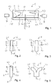
- the figure 1 shows a highly schematic conductor terminal 1 in the form of a connecting terminal.
- the conductor terminal 1 has a housing 2 which has a conductor insertion opening 20 for inserting an electrical conductor on the housing sides facing away from one another.
- a contact insert which has a busbar 3 and clamping springs 4 .
- a clamping spring 4 shown on the left is assigned to the left conductor insertion opening 20 and forms a terminal point with a section of the busbar 3 .
- the right-hand clamping spring 4 is assigned to the right-hand conductor entry opening 20 and forms a clamping point for an electrical conductor with another section of the busbar 3 . If an electrical conductor is clamped to each of the two clamping points, these electrical conductors are electrically connected to one another by the conductor rail 3 .
- the clamping springs 4 can be deflected by an actuating element of the conductor terminal 1 in such a way that a respective clamping leg 43 of the clamping spring 4 is moved away from the busbar 3 in order to open the clamping point. If the clamping point is closed, the clamping leg 43 rests either on the conductor rail 3 if no electrical conductor is plugged in, or on the electrical conductor. In the figure 1 the left spring clamp connection is shown in the closed state, the right spring clamp connection in the open state.
- a light guide element 6 is located in the housing 2 at a position between the spring-loaded terminal connections or the clamping springs 4 .
- the figure 1 also shows a test arrangement for testing the functionality of the conductor connection terminal.
- the test arrangement has a light source 7 and respective cameras 9 placed in front of the conductor insertion openings 20 .
- the light source 7 emits light 8, which is irradiated through a transparent partial area of the housing 2 and forwarded by the light-conducting element 6 and, in particular, is redirected into a light emission direction that is essentially orthogonal to the irradiation direction of the light 8.
- the light 10 emitted to the right reaches the camera 9 because the clamping point is open.
- the light 10 emitted to the left is interrupted or at least significantly reduced by the clamping leg 43 due to the closed clamping point.
- the Figures 2 to 5 show various advantageous embodiments of the light-guiding element 6.
- the light-guiding element 6 is shown in such a way that it emits the incident light 8 in two directions, ie from a right-hand light-emitting surface 60 and a left-hand light-emitting surface 61.
- the light-guiding element 6 does not necessarily have to be in two emit light in different directions.
- the light-guiding element 6 can also be designed in such a way that it only emits light in one direction, ie that, for example, only one light-emitting surface 60 or the other light-emitting surface 61 is present.
- the light-guiding element 6 has corresponding structures 62 for deflecting the incident light 8 in the light emission direction 10 in the volume of the material of the light-guiding element 6 or on the outer surface of the light-emitting surfaces 60, 61, for example in the form of microprisms.
- the figure 3 shows an embodiment in which the deflection of the light 8 in the light emission direction 10 is realized by frosted surfaces 63 of the light emission surfaces 60, 61.
- FIG. 1 shows an embodiment in which the light is deflected by a prism 64 molded into the material of the light-guiding element 6.
- the figure 5 shows an embodiment of the light-guiding element 6, in which the light-guiding element 6 divides upwards from a lower root area into one light-guiding arm 65 bent to the left and one to the right.
- the respective light-emitting surface 60, 61 is formed on the free ends of the light-guiding arms 65.
- the figure 6 shows a conductor terminal 1 with further details.
- the housing 2 is formed in at least two parts with a lower housing part 22 and an upper housing part 23 .
- the upper housing part 23 is connected to the lower housing part 22, for example by a latch.
- On the lower part of the housing 22 is the already mentioned outer wall 21, from which the light guide element 6 extends in the form of an inner housing wall of the lower housing part 22 into the interior of the housing 2.
- the busbar 3 has a busbar section 31 facing the left-hand clamping spring 4 and a busbar section 32 facing the right-hand clamping spring 4.
- the busbar 3 extends upwards via a rear section 33, which is angled in relation to the busbar sections 31, 32, to an upper section 34 of the busbar 3 , which is used to fix the clamping springs 4.
- a recess 30 into which the light guide element 6 extends at least partially.
- the clamping springs 4 each have a contact leg 41 , a spring bow 42 adjoining the contact leg 41 and a clamping leg 43 adjoining the spring bow 42 .
- the clamping point is formed between the clamping leg 43 and the respective busbar section 31, 32.
- the clamping springs are attached to the upper area 34 of the conductor rail 3 via their contact legs 41 by means of end-side curved holding elements 40, e.g. suspended in corresponding recesses of this upper area 34.
- each spring force terminal connection has an actuating element 5 in the form of a pivotable actuating lever.
- the actuating element 5 has a manual grip area 50 protruding from the housing 2 . From the manual grip area 50, a side cheek 51 of the actuating element 5 extends laterally next to the clamping spring 4, which has a part-circular contour and thereby deflects the clamping leg 43 in the manner of a cam when the actuating element 5 is pivoted and accordingly from the associated conductor rail piece 31, 32 can move.
- the clamping point can be opened or closed at will by the user with the respective actuating element 5 .
- This can also be done in accordance with a test procedure using the test arrangement figure 1 for the automatic testing of the conductor connection terminal be used.
- the actuating elements 5 can be automatically pivoted into the different positions, for example by a testing mechanism, for example a mechanical actuator.
Landscapes
- Physics & Mathematics (AREA)
- General Physics & Mathematics (AREA)
- Optics & Photonics (AREA)
- Chemical & Material Sciences (AREA)
- Analytical Chemistry (AREA)
- Measuring Leads Or Probes (AREA)
- Connections Arranged To Contact A Plurality Of Conductors (AREA)
Abstract
Description
- Die Erfindung betrifft eine Leiteranschlussklemme mit einem Gehäuse und wenigstens einem in dem Gehäuse angeordneten Federkraftklemmanschluss zum Anklemmen eines elektrischen Leiters mittels Federkraft, wobei wenigstens ein Teilbereich des Gehäuses aus optisch transparentem Material gebildet ist. Die Erfindung betrifft außerdem eine Prüfanordnung zum Prüfen der Funktionsfähigkeit einer solchen Leiteranschlussklemme und ein Verfahren zum Prüfen der Funktionsfähigkeit.
- Leiteranschlussklemmen der eingangs genannten Art sind bekannt, z.B. durch die 221-Serie der Anmelderin. Solche Leiteranschlussklemmen werden teilweise mit transparenten Gehäusen angeboten, sodass das korrekte Einstecken eines elektrischen Leiters vom Anwender visuell geprüft werden kann.
- Der Erfindung liegt die Aufgabe zugrunde, eine Leiteranschlussklemme mit weiter verbesserten Prüfmöglichkeiten anzugeben, die insbesondere auch eine Prüfung der Funktionsfähigkeit der Leiteranschlussklemme ermöglichen.
- Diese Aufgabe wird bei einer Leiteranschlussklemme der eingangs genannten Art dadurch gelöst, dass die Leiteranschlussklemme innerhalb des Gehäuses wenigstens ein Lichtleitelement hat, durch das von außen durch den optisch transparenten Teilbereich des Gehäuses in das Gehäuse eingestrahltes Licht zu einer vorbestimmten Position im Gehäuse leitbar und/oder in eine vorbestimmte Abstrahlrichtung in dem Gehäuse umlenkbar ist, die von der Einstrahlrichtung des Lichts verschieden ist. Die Erfindung hat den Vorteil, dass die Leiteranschlussklemme eine verbesserte und insbesondere auch eine vereinfachte automatische Prüfung durch eine optische Prüfanordnung ermöglicht. Dies wird durch das wenigstens eine im Gehäuse angeordnete Lichtleitelement gefördert, das es ermöglicht, von außen durch den optisch transparenten Teilbereich des Gehäuses Licht in das Gehäuse einzustrahlen und durch optische Prüfung an einer anderen Position im Gehäuse oder außerhalb des Gehäuses zu kontrollieren, ob zumindest ein Teil des eingestrahlten Lichts dort erkennbar ist. Das wenigstens eine Lichtleitelement kann ebenfalls aus optisch transparentem Material gebildet sein, z.B. aus dem gleichen Material wie der optisch transparente Teilbereich des Gehäuses oder einem anderen entsprechenden Material. Das Gehäuse kann auch insgesamt aus optisch transparentem Material ausgebildet sein.
- Als optisch transparent wird im Rahmen dieser Anmeldung insbesondere ein Material oder ein Element verstanden, das durchlässig ist für Licht im vom Menschen wahrnehmbaren Wellenlängenbereich (380-750 nm). Das optisch transparente Material kann insbesondere farblos transparent ausgebildet sein (klar).
- Die Leiteranschlussklemme kann insbesondere ohne eigene Lichtquelle ausgebildet sein. Das wenigstens eine Lichtleitelement dient daher nicht zum Leiten von Licht aus dem Gehäuse heraus, sondern zum Weiterleiten von in das Gehäuse eingestrahltem Licht. Die Leiteranschlussklemme kann insgesamt als passives Bauteil ausgebildet sein, z.B. als ein elektromechanisches Bauteil ohne Elektronik-Komponenten.
- Gemäß einer vorteilhaften Ausgestaltung der Erfindung ist vorgesehen, dass das wenigstens eine Lichtleitelement als innerhalb des Gehäuses angeordnete Gehäusewand ausgebildet ist. Dies hat den Vorteil, dass z.B. eine ohnehin im Gehäuse angeordnete Gehäusewand als Lichtleitelement genutzt werden kann. Dementsprechend ist nicht unbedingt ein zusätzliches Bauteil für das Lichtleitelement erforderlich. Das Lichtleitelement kann insbesondere integral (einstückig) mit dem Gehäuse ausgeformt sein.
- Gemäß einer vorteilhaften Ausgestaltung der Erfindung ist vorgesehen, dass sich das wenigstens eine Lichtleitelement orthogonal von einer Außenwand des Gehäuses aus in das Innere des Gehäuses erstreckt. Dies hat den Vorteil, dass durch die Außenwand mittels einer Lichtquelle auf einfache Weise, nämlich in orthogonaler Richtung zur Außenwand, das in das Gehäuse einzustrahlende Licht abgegeben werden kann. Auf diese Weise kann insbesondere eine einfache Prüfung der Funktionsfähigkeit der Leiteranschlussklemme mittels einer Prüfanordnung automatisiert erfolgen. Das wenigstens eine Lichtleitelement kann sich von der Außenwand des Gehäuses aus bis zu einer gegenüberliegenden Außenwand des Gehäuses erstrecken, oder bereits vor der gegenüberliegenden Außenwand enden und dementsprechend als stummelartige Gehäusewand ausgebildet sein.
- Gemäß einer vorteilhaften Ausgestaltung der Erfindung ist vorgesehen, dass das wenigstens eine Lichtleitelement einen Leiteranschlag zur Begrenzung der Einstecktiefe eines am Federkraftklemmanschluss anzuklemmenden elektrischen Leiters bildet. Dies hat den Vorteil, dass das Lichtleitelement noch eine weitere Funktion, neben der Lichtleitung, übernehmen kann. Hierdurch kann die Leiteranschlussklemme kompakt gestaltet werden, da nicht unbedingt ein weiteres Bauteil für die Begrenzung der Einstecktiefe des elektrischen Leiters erforderlich ist.
- Gemäß einer vorteilhaften Ausgestaltung der Erfindung ist vorgesehen, dass die Leiteranschlussklemme wenigstens eine Leitereinführöffnung hat, durch die ein am Federkraftklemmanschluss anzuklemmender elektrischer Leiter in einer Leitereinführrichtung in das Gehäuse einführbar ist, wobei das wenigstens eine Lichtleitelement zur Umlenkung des durch den optisch transparenten Teilbereich des Gehäuses in das Gehäuse eingestrahlten Lichts zur Leitereinführöffnung hin eingerichtet ist. Dies hat den Vorteil, dass durch die Leitereinführöffnung somit eine optische Prüfung des in das Gehäuse eingestrahlten Lichts durchgeführt werden kann. Beispielsweise wird das Licht in einer orthogonalen Richtung zur Leitereinführrichtung in das Gehäuse eingestrahlt und kann dennoch durch die Leitereinführöffnung geprüft werden.
- Gemäß einer vorteilhaften Ausgestaltung der Erfindung ist vorgesehen, dass das wenigstens eine Lichtleitelement zur Umlenkung des durch den optisch transparenten Teilbereich des Gehäuses in das Gehäuse eingestrahlten Lichts in einem Winkel von 60 bis 120 Grad, insbesondere 90 Grad, eingerichtet ist. Dies hat den Vorteil, dass die Prüfanordnung für eine automatische Prüfung der Leiteranschlussklemme mittels des eingestrahlten Lichts einfach gestaltet werden kann und eine schnelle automatisierte Prüfung möglich ist.
- Gemäß einer vorteilhaften Ausgestaltung der Erfindung ist vorgesehen, dass das wenigstens eine Lichtleitelement als optisch transparentes Kunststoffteil ausgebildet ist, das wenigstens eine Lichtabstrahlfläche zur Abstrahlung des durch den optisch transparenten Teilbereich des Gehäuses in das Gehäuse eingestrahlten Lichts in das Gehäuse hat, wobei die wenigstens eine Lichtabstrahlfläche eine mattierte Oberfläche hat. Dies hat den Vorteil, dass die Umlenkung des eingestrahlten Lichts mit einfachen Mitteln erfolgen kann, die insbesondere fertigungstechnisch bei einer Leiteranschlussklemme leicht realisierbar sind. So kann das Lichtleitelement beispielsweise direkt im Kunststoff-Spritzgießprozess bei der Herstellung des Gehäuses integral mit erzeugt werden. Dadurch, dass die Lichtabstrahlfläche lediglich mattiert ist, ergeben sich auch keine Probleme bei der Entformung des Gehäuses mit dem Lichtleitelement. Die mattierte Oberfläche kann z.B. dadurch realisiert werden, dass eine entsprechende aufgeraute Oberfläche, z.B. mit erodierter Struktur, im Spritzgießwerkzeug an der gewünschten Stelle erzeugt wird, die dann im Spritzgießprozess abgeformt wird. Die mattierte Oberfläche kann z.B. eine Oberflächenrauigkeit von Ra 0,4 bis Ra 18 haben. Es können z.B. die Oberflächen-Klassen 12 bis 45, insbesondere 21 bis 24, gemäß VDI 3400 realisiert sein.
- Alternativ oder zusätzlich zur mattierten Oberfläche kann die Lichtabstrahlfläche auch in anderer Weise strukturiert sein, z.B. mit Mikroprismen. Das Lichtleitelement kann z.B. als im Wesentlichen quaderförmiges Kunststoffbauteil mit zueinander parallelen Seitenwänden ausgebildet sein. Das Lichtleitelement kann auch als sich zum freien Ende hin verjüngendes Kunststoffbauteil ausgebildet sein, beispielsweise mit konischem Querschnitt.
- Gemäß einer vorteilhaften Ausgestaltung der Erfindung ist vorgesehen, dass die wenigstens eine Lichtabstrahlfläche schräg oder rechtwinklig zur Leitereinführrichtung angeordnet ist. Auf diese Weise ist eine deutliche Lichtumlenkung um einen erheblichen Winkel möglich, was wiederum die automatische Prüfung der Leiteranschlussklemme vereinfacht. Ist die Lichtabstrahlfläche schräg zur Leitereinführrichtung angeordnet, so kann der Winkel zwischen der Leitereinführrichtung und der Lichtabstrahlfläche beispielsweise im Bereich von 70 bis 110 Grad liegen.
- Gemäß einer vorteilhaften Ausgestaltung der Erfindung ist vorgesehen, dass die Leiteranschlussklemme als Verbindungsklemme ausgebildet ist, die wenigstens zwei galvanisch miteinander verbundene Federkraftklemmanschlüsse hat, an denen jeweils ein elektrischer Leiter mittels Federkraft anklemmbar ist, wobei jedem der Federkraftklemmanschlüsse eine Leitereinführöffnung im Gehäuse zugeordnet ist, wobei die Leitereinführöffnungen auf voneinander abgewandten Seiten des Gehäuses angeordnet sind. Eine solche Verbindungsklemme eignet sich besonders gut zum Verbinden elektrischer Leitungen, die aus entgegengesetzten Richtungen aufeinander zu laufen, oder zum Reparieren von unterbrochenen elektrischen Leitungen.
- Gemäß einer vorteilhaften Ausgestaltung der Erfindung ist vorgesehen, dass das wenigstens eine Lichtleitelement zwischen den wenigstens zwei galvanisch miteinander verbundenen Federkraftklemmanschlüssen angeordnet ist. Das Lichtleitelement kann z.B. in Bezug auf die Längsrichtung der Leiteranschlussklemme mittig darin angeordnet sein.
- Gemäß einer vorteilhaften Ausgestaltung der Erfindung ist vorgesehen, dass die wenigstens zwei galvanisch miteinander verbundenen Federkraftklemmanschlüsse durch eine durchgehende Stromschiene miteinander verbunden sind.
- Gemäß einer vorteilhaften Ausgestaltung der Erfindung ist vorgesehen, dass der Federkraftklemmanschluss oder beide galvanisch miteinander verbundenen Federkraftklemmanschlüsse jeweils eine Klemmfeder und ein mit der Klemmfeder verbundenes Stromschienenstück aufweisen, wobei die Klemmfeder wenigstens einen Klemmschenkel hat, dessen freies Ende zur Stromschiene ausgerichtet ist. Der Klemmschenkel kann am freien Ende eine Klemmkante haben. Zwischen dem freien Ende des Klemmschenkels und dem Stromschienenstück wird eine Klemmstelle zum Anklemmen des elektrischen Leiters gebildet.
- Gemäß einer vorteilhaften Ausgestaltung der Erfindung ist vorgesehen, dass der Klemmschenkel an dem ihm zugeordneten Stromschienenstück anlegbar ist, wobei der Klemmschenkel im Lichtstrahlenweg von dem wenigstens einen Lichtleitelement zur Leitereinführöffnung angeordnet ist, wenn er an dem ihm zugeordneten Stromschienenstück anliegt. Dies hat den Vorteil, dass durch den Klemmschenkel der durch die Leitereinführungsöffnung sichtbare Anteil des eingestrahlten Lichts unterbrechbar oder zumindest verringerbar ist, wenn die Klemmstelle geschlossen ist. Bei geöffneter Klemmstelle lässt der Klemmschenkel das Licht durch, sodass mittels einer optischen Prüfung auf einfache Weise die Funktion der Betätigung des Klemmschenkels und dessen Anliegen am Stromschienenstück geprüft werden kann.
- Gemäß einer vorteilhaften Ausgestaltung der Erfindung ist vorgesehen, dass die Leiteranschlussklemme wenigstens ein Betätigungselement zur Betätigung des wenigstens einen Federkraftklemmanschlusses hat, wobei durch manuelle Betätigung des Betätigungselements eine am Federkraftklemmanschluss gebildete Klemmstelle zum Anklemmen des elektrischen Leiters geöffnet werden kann. Das Betätigungselement kann z.B. als verschwenkbarer Betätigungshebel ausgebildet sein. Insbesondere kann ein solcher Betätigungshebel im Querschnitt eine U-Form haben, wobei der Betätigungshebel jeweils links und rechts von einem manuellen Betätigungsabschnitt abragende Seitenwangen haben kann. Zwischen den Seitenwangen ist dann ein Zwischenraum gebildet, durch den der elektrische Leiter zur Klemmstelle geführt werden kann. Der Betätigungshebel übergreift somit durch seine Seitenwangen den angeklemmten elektrischen Leiter.
- Die eingangs genannte Aufgabe wird außerdem gelöst durch eine Prüfanordnung zum Prüfen der Funktionsfähigkeit einer Leiteranschlussklemme der zuvor erläuterten Art, wobei die Prüfanordnung wenigstens eine auf den optisch transparenten Teilbereich des Gehäuses gerichtete Lichtquelle und eine auf einen anderen optisch transparenten Teilbereich des Gehäuses oder auf die Leitereinführöffnung gerichtete Kamera hat. Dies hat den Vorteil, dass die Funktionsfähigkeit der Leiteranschlussklemme mit einfachen Mitteln geprüft werden kann, insbesondere in einer automatisierten Prüfung. Die Prüfung kann mit sichtbarem Licht erfolgen.
- Vorteilhafter Weise kann dabei das folgende Verfahren zum Prüfen der Funktionsfähigkeit der Leiteranschlussklemme durchgeführt werden:
- a) Anordnen der Leiteranschlussklemme an einer Prüfanordnung der zuvor erläuterten Art,
- b) Einstrahlen von Licht in das Gehäuse der Leiteranschlussklemme durch den optisch transparenten Teilbereich des Gehäuses mittels der Lichtquelle,
- c) Aufnehmen wenigstens eines ersten Bilds mit der Kamera, wenn die Klemmstelle der Leiteranschlussklemme geöffnet ist,
- d) Aufnehmen wenigstens eines zweiten Bilds mit der Kamera, wenn die Klemmstelle der Leiteranschlussklemme geschlossen ist,
- e) Prüfen, ob in dem wenigstens einen ersten Bild das vom Lichtleitelement abgestrahlte Licht im Wesentlichen vollständig erkennbar ist,
- f) Prüfen, ob in dem wenigstens einen zweiten Bild das vom Lichtleitelement abgestrahlte Licht im Wesentlichen nicht erkennbar ist,
- g) Feststellen, dass die Leiteranschlussklemme funktionsfähig ist, wenn beide Prüfungen in den Merkmalen e) und f) positive Ergebnisse zeigen,
- h) andernfalls feststellen, dass die Leiteranschlussklemme nicht funktionsfähig ist.
- Im Sinne der vorliegenden Erfindung ist unter dem unbestimmten Begriff "ein" kein Zahlwort zu verstehen. Wenn also z.B. von einem Bauteil die Rede ist, so ist dies im Sinne von "mindestens einem Bauteil" zu interpretieren. Soweit Winkelangaben in Grad gemacht werden, beziehen sich diese auf ein Kreismaß von 360 Grad (360°).
- Die Erfindung wird nachfolgend anhand von Ausführungsbeispielen unter Verwendung von Zeichnungen näher erläutert.
- Es zeigen
- Figur 1
- eine Leiteranschlussklemme in seitlicher Schnittdarstellung mit einer Prüfanordnung,
- Figuren 2 bis 5
- verschiedene Ausführungsformen eines Lichtleitelementes,
- Figur 6
- eine Leiteranschlussklemme in seitlicher Schnittdarstellung mit weiteren Details.
- Die
Figur 1 zeigt stark schematisiert eine Leiteranschlussklemme 1 in Form einer Verbindungsklemme. Die Leiteranschlussklemme 1 weist ein Gehäuse 2 auf, das an voneinander abgewandten Gehäuseseiten jeweils eine Leitereinführungsöffnung 20 zum Einführen eines elektrischen Leiters hat. In dem Gehäuse 2 befindet sich ein Kontakteinsatz, der eine Stromschiene 3 und Klemmfedern 4 aufweist. Eine links dargestellte Klemmfeder 4 ist der linken Leitereinführungsöffnung 20 zugeordnet und bildet mit einem Abschnitt der Stromschiene 3 eine Klemmstelle. Die rechte Klemmfeder 4 ist der rechten Leitereinführungsöffnung 20 zugeordnet und bildet mit einem weiteren Abschnitt der Stromschiene 3 eine Klemmstelle für einen elektrischen Leiter. Wird an beiden Klemmstellen jeweils ein elektrischer Leiter angeklemmt, so sind diese elektrischen Leiter durch die Stromschiene 3 miteinander galvanisch verbunden. - Die Klemmfedern 4 können durch ein Betätigungselement der Leiteranschlussklemme 1 ausgelenkt werden, derart, dass ein jeweiliger Klemmschenkel 43 der Klemmfeder 4 von der Stromschiene 3 fortbewegt wird, um die Klemmstelle zu öffnen. Wird die Klemmstelle geschlossen, liegt der Klemmschenkel 43 entweder an der Stromschiene 3 an, wenn kein elektrischer Leiter eingesteckt ist, oder an dem elektrischen Leiter an. In der
Figur 1 ist der linke Federkraftklemmanschluss im geschlossenen Zustand dargestellt, der rechte Federkraftklemmanschluss im geöffneten Zustand. - In dem Gehäuse 2 befindet sich ein Lichtleitelement 6 an einer Position zwischen den Federkraftklemmanschlüssen bzw. den Klemmfedern 4. Das Lichtleitelement 6 ist als im Wesentlichen orthogonal zu einer unteren Außenwand 21 des Gehäuses 2 abragender Wandabschnitt ausgebildet.
- Die
Figur 1 zeigt zudem eine Prüfanordnung zum Prüfen der Funktionsfähigkeit der Leiteranschlussklemme. Die Prüfanordnung weist eine Lichtquelle 7 und jeweilige vor den Leitereinführungsöffnungen 20 platzierte Kameras 9 auf. Bei einem Prüfvorgang gibt die Lichtquelle 7 Licht 8 ab, das durch einen transparenten Teilbereich des Gehäuses 2 eingestrahlt wird und durch das Lichtleitelement 6 weitergeleitet und insbesondere in eine Lichtabstrahlrichtung umgeleitet wird, die im Wesentlichen orthogonal zur Einstrahlrichtung des Lichts 8 ist. Man erkennt in derFigur 1 , dass von dem Lichtleitelement 6 das Licht sowohl zur rechten Leitereinführöffnung 20 als auch zur linken Leitereinführöffnung 20 als Lichtstrahlen 10 abgestrahlt wird. Das nach rechts abgestrahlte Licht 10 erreicht, weil die Klemmstelle geöffnet ist, die Kamera 9. Das nach links abgestrahlte Licht 10 wird durch den Klemmschenkel 43 aufgrund der geschlossenen Klemmstelle unterbrochen oder zumindest deutlich vermindert. Durch Auswertung der Bilder der Kameras 9 kann geprüft werden, ob eine Klemmstelle wie gewünscht geöffnet oder geschlossen ist. Aufgrund dessen kann auf die Funktionsfähigkeit der Betätigungsmechanik sowie die korrekte Anordnung der Klemmfedern geschlossen werden. Auf diese Weise kann eine automatische Prüfung der Funktionsfähigkeit der Leiteranschlussklemme 1 durchgeführt werden. - Die
Figuren 2 bis 5 zeigen verschiedene vorteilhafte Ausführungsformen des Lichtleitelementes 6. Das Lichtleitelement 6 ist in allen Ausführungsformen so dargestellt, dass es das eingestrahlte Licht 8 in zwei Richtungen abstrahlt, d.h. von einer rechten Lichtabstrahlfläche 60 und einer linken Lichtabstrahlfläche 61. Das Lichtleitelement 6 muss aber nicht unbedingt in zwei Richtungen Licht abstrahlen. Das Lichtleitelement 6 kann auch derart ausgebildet sein, dass es nur in eine Richtung Licht abstrahlt, d.h. das z.B. nur die eine Lichtabstrahlfläche 60 oder die andere Lichtabstrahlfläche 61 vorhanden ist. - In der Ausführungsform der
Figur 2 weist das Lichtleitelement 6 zur Umlenkung des eingestrahlten Lichts 8 in die Lichtabstrahlrichtung 10 im Volumen des Materials des Lichtleitelementes 6 oder an der Außenoberfläche der Lichtabstrahlflächen 60, 61 entsprechende Strukturierungen 62 auf, z.B. in Form von Mikroprismen. - Die
Figur 3 zeigt eine Ausführungsform, bei der die Umlenkung des Lichts 8 in die Lichtabstrahlrichtung 10 durch mattierte Oberflächen 63 der Lichtabstrahlflächen 60, 61 realisiert ist. - Die
Figur 4 zeigt eine Ausführungsform, bei der die Lichtumlenkung durch ein im Material des Lichtleitelementes 6 eingeformtes Prisma 64 erfolgt. - Die
Figur 5 zeigt eine Ausführungsform des Lichtleitelementes 6, bei dem sich das Lichtleitelement 6 vom einem unteren Wurzelbereich nach oben hin aufteilt in jeweils einen nach links und einen nach rechts gebogenen Lichtleitarm 65. An den freien Enden der Lichtleitarme 65 ist die jeweilige Lichtabstrahlfläche 60, 61 ausgebildet. - Die
Figur 6 zeigt eine Leiteranschlussklemme 1 mit weiteren Details. Man erkennt, dass das Gehäuse 2 zumindest zweiteilig mit einem unteren Gehäuseteil 22 und einem oberen Gehäuseteil 23 ausgebildet ist. Das obere Gehäuseteil 23 ist mit dem unteren Gehäuseteil 22 verbunden, z.B. durch eine Verrastung. Am unteren Gehäuseteil 22 befindet sich die bereits erwähnte Außenwand 21, von der aus sich das Lichtleitelement 6 in Form einer inneren Gehäusewand des unteren Gehäuseteils 22 in das Innere des Gehäuses 2 erstreckt. - In dem Gehäuse 2 befindet sich ein Kontakteinsatz, der wiederum eine Stromschiene 3 und die zwei Klemmfedern 4 aufweist. Die Stromschiene 3 hat einen zur linken Klemmfeder 4 gewandten Stromschienenabschnitt 31 und einen zur rechten Klemmfeder 4 gewandten Stromschienenabschnitt 32. Die Stromschiene 3 erstreckt sich über einen gegenüber den Stromschienenabschnitten 31, 32 abgewinkelten rückwärtigen Abschnitt 33 nach oben hin zu einem oberen Abschnitt 34 der Stromschiene 3, der zur Fixierung der Klemmfedern 4 dient. In dem rückwärtigen Abschnitt 33 ist eine Aussparung 30 vorhanden, in die sich das Lichtleitelement 6 zumindest teilweise hineinerstreckt.
- Die Klemmfedern 4 weisen jeweils einen Anlageschenkel 41, einen sich an den Anlageschenkel 41 anschließenden Federbogen 42 und einen sich an den Federbogen 42 anschließenden Klemmschenkel 43 auf. Zwischen dem Klemmschenkel 43 und dem jeweiligen Stromschienenabschnitt 31, 32 ist die Klemmstelle gebildet. Die Klemmfedern sind über ihre Anlageschenkel 41 mittels endseitigen gekrümmten Halteelementen 40 an dem oberen Bereich 34 der Stromschiene 3 befestigt, z.B. in entsprechenden Aussparungen dieses oberen Bereiches 34 eingehängt.
- Zur Betätigung der Klemmfedern 4 weist jeder Federkraftklemmanschluss ein Betätigungselement 5 in Form eines verschwenkbaren Betätigungshebels auf. Das Betätigungselement 5 weist einen aus dem Gehäuse 2 herausragenden manuellen Griffbereich 50 auf. Vom manuellen Griffbereich 50 erstreckt sich jeweils seitlich neben der Klemmfeder 4 entlang eine Seitenwange 51 des Betätigungselements 5, die eine teilkreisförmige Kontur hat und hierdurch in der Art eines Nockens bei einem Verschwenken des Betätigungselementes 5 den Klemmschenkel 43 auslenken und dementsprechend vom zugeordneten Stromschienenstück 31, 32 fortbewegen kann.
- Durch das jeweilige Betätigungselement 5 kann durch den Anwender willkürlich die Klemmstelle geöffnet oder geschlossen werden. Dies kann auch bei einem Prüfvorgang mittels der Prüfanordnung gemäß
Figur 1 für die automatische Prüfung der Leiteranschlussklemme genutzt werden. Bei der automatischen Prüfung der Leiteranschlussklemme können die Betätigungselemente 5 beispielsweise durch einen Prüfmechanismus, z.B. ein mechanisches Stellglied, automatisch in die unterschiedlichen Stellungen verschwenkt werden.
Claims (16)
- Leiteranschlussklemme (1) mit einem Gehäuse (2) und wenigstens einem in dem Gehäuse (2) angeordneten Federkraftklemmanschluss zum Anklemmen eines elektrischen Leiters mittels Federkraft, wobei wenigstens ein Teilbereich des Gehäuses (2) aus optisch transparentem Material gebildet ist, dadurch gekennzeichnet, dass die Leiteranschlussklemme (1) innerhalb des Gehäuses (2) wenigstens ein Lichtleitelement (6) hat, durch das von außen durch den optisch transparenten Teilbereich des Gehäuses (2) in das Gehäuse (2) eingestrahltes Licht (8) zu einer vorbestimmten Position im Gehäuse (2) leitbar und/oder in eine vorbestimmte Abstrahlrichtung in dem Gehäuse (2) umlenkbar ist, die von der Einstrahlrichtung des Lichts (8) verschieden ist.
- Leiteranschlussklemme nach Anspruch 1, dadurch gekennzeichnet, dass das wenigstens eine Lichtleitelement (6) als innerhalb des Gehäuses (2) angeordnete Gehäusewand ausgebildet ist.
- Leiteranschlussklemme nach einem der vorhergehenden Ansprüche, dadurch gekennzeichnet, dass sich das wenigstens eine Lichtleitelement (6) orthogonal von einer Außenwand (21) des Gehäuses (2) aus in das Innere des Gehäuses (2) erstreckt.
- Leiteranschlussklemme nach einem der vorhergehenden Ansprüche, dadurch gekennzeichnet, dass das wenigstens eine Lichtleitelement (6) einen Leiteranschlag zur Begrenzung der Einstecktiefe eines am Federkraftklemmanschluss anzuklemmenden elektrischen Leiters bildet.
- Leiteranschlussklemme nach einem der vorhergehenden Ansprüche, dadurch gekennzeichnet, dass die Leiteranschlussklemme (1) wenigstens eine Leitereinführöffnung (20) hat, durch die ein am Federkraftklemmanschluss anzuklemmender elektrischer Leiter in einer Leitereinführrichtung in das Gehäuse (2) einführbar ist, wobei das wenigstens eine Lichtleitelement (6) zur Umlenkung des durch den optisch transparenten Teilbereich des Gehäuses (2) in das Gehäuse (2) eingestrahlten Lichts (8) zur Leitereinführöffnung (20) hin eingerichtet ist.
- Leiteranschlussklemme nach einem der vorhergehenden Ansprüche, dadurch gekennzeichnet, dass das wenigstens eine Lichtleitelement (6) zur Umlenkung des durch den optisch transparenten Teilbereich des Gehäuses (2) in das Gehäuse (2) eingestrahlten Lichts (8) in einem Winkel von 60 bis 120 Grad, insbesondere 90 Grad, eingerichtet ist.
- Leiteranschlussklemme nach einem der vorhergehenden Ansprüche, dadurch gekennzeichnet, dass das wenigstens eine Lichtleitelement (6) als optisch transparentes Kunststoffteil ausgebildet ist, das wenigstens eine Lichtabstrahlfläche (60, 61) zur Abstrahlung des durch den optisch transparenten Teilbereich des Gehäuses (2) in das Gehäuse (2) eingestrahlten Lichts (8) in das Gehäuse (2) hat, wobei die wenigstens eine Lichtabstrahlfläche (60, 61) eine mattierte Oberfläche hat.
- Leiteranschlussklemme nach Anspruch 7, dadurch gekennzeichnet, dass die wenigstens eine Lichtabstrahlfläche (60, 61) schräg oder rechtwinklig zur Leitereinführrichtung angeordnet ist.
- Leiteranschlussklemme nach einem der vorhergehenden Ansprüche, dadurch gekennzeichnet, dass die Leiteranschlussklemme (1) als Verbindungsklemme ausgebildet ist, die wenigstens zwei galvanisch miteinander verbundene Federkraftklemmanschlüsse hat, an denen jeweils ein elektrischer Leiter mittels Federkraft anklemmbar ist, wobei jedem der Federkraftklemmanschlüsse eine Leitereinführöffnung (20) im Gehäuse (2) zugeordnet ist, wobei die Leitereinführöffnungen (20) auf voneinander abgewandten Seiten des Gehäuses (2) angeordnet sind.
- Leiteranschlussklemme nach Anspruch 9, dadurch gekennzeichnet, dass das wenigstens eine Lichtleitelement (6) zwischen den wenigstens zwei galvanisch miteinander verbundenen Federkraftklemmanschlüssen angeordnet ist.
- Leiteranschlussklemme nach einem der Ansprüche 9 bis 10, dadurch gekennzeichnet, dass die wenigstens zwei galvanisch miteinander verbundenen Federkraftklemmanschlüsse durch eine durchgehende Stromschiene (3) miteinander verbunden sind.
- Leiteranschlussklemme nach einem der vorhergehenden Ansprüche, dadurch gekennzeichnet, dass der Federkraftklemmanschluss oder beide galvanisch miteinander verbundenen Federkraftklemmanschlüsse jeweils eine Klemmfeder (4) und ein mit der Klemmfeder (4) verbundenes Stromschienenstück (31, 32) aufweisen, wobei die Klemmfeder (4) wenigstens einen Klemmschenkel (43) hat, dessen freies Ende zur Stromschiene (3) ausgerichtet ist.
- Leiteranschlussklemme nach Anspruch 12, dadurch gekennzeichnet, dass der Klemmschenkel (43) an dem ihm zugeordneten Stromschienenstück (31, 32) anlegbar ist, wobei der Klemmschenkel (43) im Lichtstrahlenweg von dem wenigstens einen Lichtleitelement (6) zur Leitereinführöffnung (20) angeordnet ist, wenn er an dem ihm zugeordneten Stromschienenstück (31, 32) anliegt.
- Leiteranschlussklemme nach einem der vorhergehenden Ansprüche, dadurch gekennzeichnet, dass die Leiteranschlussklemme (1) wenigstens ein Betätigungselement (5) zur Betätigung des wenigstens einen Federkraftklemmanschlusses hat, wobei durch manuelle Betätigung des Betätigungselements (5) eine am Federkraftklemmanschluss gebildete Klemmstelle zum Anklemmen des elektrischen Leiters geöffnet werden kann.
- Prüfanordnung zum Prüfen der Funktionsfähigkeit einer Leiteranschlussklemme (1) nach einem der vorhergehenden Ansprüche, wobei die Prüfanordnung wenigstens eine auf den optisch transparenten Teilbereich des Gehäuses (2) gerichtete Lichtquelle (7) und eine auf einen anderen optisch transparenten Teilbereich des Gehäuses (2) oder auf die Leitereinführöffnung (20) gerichtete Kamera (9) hat.
- Verfahren zum Prüfen der Funktionsfähigkeit einer Leiteranschlussklemme nach einem der Ansprüche 1 bis 14 mit folgenden Schritten:a) Anordnen der Leiteranschlussklemme (1) an einer Prüfanordnung nach Anspruch 15,b) Einstrahlen von Licht (8) in das Gehäuse (2) der Leiteranschlussklemme (1) durch den optisch transparenten Teilbereich des Gehäuses (2) mittels der Lichtquelle (7),c) Aufnehmen wenigstens eines ersten Bilds mit der Kamera (9), wenn die Klemmstelle der Leiteranschlussklemme (1) geöffnet ist,d) Aufnehmen wenigstens eines zweiten Bilds mit der Kamera (9), wenn die Klemmstelle der Leiteranschlussklemme (1) geschlossen ist,e) Prüfen, ob in dem wenigstens einen ersten Bild das vom Lichtleitelement (6) abgestrahlte Licht im Wesentlichen vollständig erkennbar ist,f) Prüfen, ob in dem wenigstens einen zweiten Bild das vom Lichtleitelement (6) abgestrahlte Licht im Wesentlichen nicht erkennbar ist,g) Feststellen, dass die Leiteranschlussklemme (1) funktionsfähig ist, wenn beide Prüfungen in den Merkmalen e) und f) positive Ergebnisse zeigen,h) andernfalls feststellen, dass die Leiteranschlussklemme (1) nicht funktionsfähig ist.
Applications Claiming Priority (1)
| Application Number | Priority Date | Filing Date | Title |
|---|---|---|---|
| DE102021102232.0A DE102021102232A1 (de) | 2021-02-01 | 2021-02-01 | Leiteranschlussklemme, Prüfanordnung und Prüfverfahren |
Publications (2)
| Publication Number | Publication Date |
|---|---|
| EP4037105A1 true EP4037105A1 (de) | 2022-08-03 |
| EP4037105B1 EP4037105B1 (de) | 2026-03-04 |
Family
ID=80122653
Family Applications (1)
| Application Number | Title | Priority Date | Filing Date |
|---|---|---|---|
| EP22153970.3A Active EP4037105B1 (de) | 2021-02-01 | 2022-01-28 | Leiteranschlussklemme, prüfanordnung und prüfverfahren |
Country Status (3)
| Country | Link |
|---|---|
| EP (1) | EP4037105B1 (de) |
| CN (1) | CN114843800A (de) |
| DE (1) | DE102021102232A1 (de) |
Cited By (1)
| Publication number | Priority date | Publication date | Assignee | Title |
|---|---|---|---|---|
| US20210387537A1 (en) * | 2019-02-28 | 2021-12-16 | Abb Schweiz Ag | Connector for electric vehicle supply equipment |
Citations (7)
| Publication number | Priority date | Publication date | Assignee | Title |
|---|---|---|---|---|
| DE19512915C1 (de) * | 1995-03-26 | 1996-08-29 | Pepperl & Fuchs | Vorrichtung zum Umlenken von Licht in Vorzugsrichtungen eines Licht aussendenden Leuchtkörpers und damit ausgerüstetes elektrisches Verbindungsteil, wie Stecker oder Buchse |
| EP1315240A1 (de) * | 2001-11-24 | 2003-05-28 | Murr-Elektronik Gesellschaft mit beschränkter Haftung | Kabelklemme mit optischer Anzeige |
| DE102014119421A1 (de) * | 2014-12-22 | 2016-06-23 | Wago Verwaltungsgesellschaft Mbh | Verbindungsklemme und Verfahren zur Montage einer Verbindungsklemme |
| DE202016101052U1 (de) * | 2016-02-29 | 2017-05-30 | Wago Verwaltungsgesellschaft Mbh | Anschlussklemme und Lichtleiter |
| US10490916B1 (en) * | 2018-11-13 | 2019-11-26 | Dinkle Enterprise Co., Ltd. | Light-emitting terminal block structure |
| DE102020107435A1 (de) * | 2019-03-29 | 2020-10-01 | Metzner Holding GmbH | Vorrichtung, Verfahren und System zur Konfektionierung eines elektrischen Kabels |
| CN110299621B (zh) * | 2018-03-23 | 2020-11-06 | 町洋企业股份有限公司 | 具有导光柱的端子台 |
Family Cites Families (5)
| Publication number | Priority date | Publication date | Assignee | Title |
|---|---|---|---|---|
| DE3784244D1 (de) * | 1987-11-07 | 1993-03-25 | Weidmueller Interface | Leiterplattenanschlusselement. |
| US7513793B2 (en) * | 2006-12-22 | 2009-04-07 | Tyco Electronics Corporation | Surface mount poke in connector |
| DE102013101830B4 (de) | 2013-01-08 | 2017-12-28 | Wago Verwaltungsgesellschaft Mbh | Elektrische Anschlussklemme und Verfahren zu dessen Montage |
| DE202016106294U1 (de) * | 2016-11-10 | 2018-02-14 | Weidmüller Interface GmbH & Co. KG | Anschlussvorrichtung mit einer Anschlussklemme für ein Leiterende |
| DE102019119725A1 (de) * | 2019-06-25 | 2020-12-31 | Metzner Maschinenbau Gmbh | Verfahren, Vorrichtung und System zur Konfektionierung eines elektrischen Kabels |
-
2021
- 2021-02-01 DE DE102021102232.0A patent/DE102021102232A1/de active Pending
-
2022
- 2022-01-28 EP EP22153970.3A patent/EP4037105B1/de active Active
- 2022-01-29 CN CN202210111372.6A patent/CN114843800A/zh active Pending
Patent Citations (7)
| Publication number | Priority date | Publication date | Assignee | Title |
|---|---|---|---|---|
| DE19512915C1 (de) * | 1995-03-26 | 1996-08-29 | Pepperl & Fuchs | Vorrichtung zum Umlenken von Licht in Vorzugsrichtungen eines Licht aussendenden Leuchtkörpers und damit ausgerüstetes elektrisches Verbindungsteil, wie Stecker oder Buchse |
| EP1315240A1 (de) * | 2001-11-24 | 2003-05-28 | Murr-Elektronik Gesellschaft mit beschränkter Haftung | Kabelklemme mit optischer Anzeige |
| DE102014119421A1 (de) * | 2014-12-22 | 2016-06-23 | Wago Verwaltungsgesellschaft Mbh | Verbindungsklemme und Verfahren zur Montage einer Verbindungsklemme |
| DE202016101052U1 (de) * | 2016-02-29 | 2017-05-30 | Wago Verwaltungsgesellschaft Mbh | Anschlussklemme und Lichtleiter |
| CN110299621B (zh) * | 2018-03-23 | 2020-11-06 | 町洋企业股份有限公司 | 具有导光柱的端子台 |
| US10490916B1 (en) * | 2018-11-13 | 2019-11-26 | Dinkle Enterprise Co., Ltd. | Light-emitting terminal block structure |
| DE102020107435A1 (de) * | 2019-03-29 | 2020-10-01 | Metzner Holding GmbH | Vorrichtung, Verfahren und System zur Konfektionierung eines elektrischen Kabels |
Cited By (2)
| Publication number | Priority date | Publication date | Assignee | Title |
|---|---|---|---|---|
| US20210387537A1 (en) * | 2019-02-28 | 2021-12-16 | Abb Schweiz Ag | Connector for electric vehicle supply equipment |
| US12083907B2 (en) * | 2019-02-28 | 2024-09-10 | ABB E-mobility B.V. | Connector for electric vehicle supply equipment |
Also Published As
| Publication number | Publication date |
|---|---|
| DE102021102232A1 (de) | 2022-08-04 |
| CN114843800A (zh) | 2022-08-02 |
| EP4037105B1 (de) | 2026-03-04 |
Similar Documents
| Publication | Publication Date | Title |
|---|---|---|
| DE60128235T2 (de) | Drahtverbinder | |
| DE102015119407B4 (de) | Anschlussklemme und Mehrfachklemme | |
| DE102016100755A1 (de) | Elektrischer Steckverbinder und Verfahren zu dessen Montage | |
| EP4037105B1 (de) | Leiteranschlussklemme, prüfanordnung und prüfverfahren | |
| EP3813203A1 (de) | Kabelprüfvorrichtung | |
| DE3641492C2 (de) | ||
| DE4429442C2 (de) | Prüfvorrichtung und Verfahren zur Prüfung von elektrischen Steckverbinder | |
| WO2012163692A1 (de) | Elektrische anschlussvorrichtung mit einem rückhaltemittel zur positionierung einer kontaktfeder in einem grundzustand | |
| DE202020100782U1 (de) | Leiteranschlussklemme | |
| DE202017100871U1 (de) | Anschlussvorrichtung für ein Leiterende | |
| DE102017125193A1 (de) | Prüfbarkeit der sekundären Verriegelungslasche in Endverraststellung | |
| EP4318812B1 (de) | Anordnung mit leitermarkierelement und verfahren zum kennzeichnen und anschliessen eines elektrischen leiters | |
| DE19709054C1 (de) | Prüfstecker mit Betätigungswerkzeug | |
| DE202018105829U1 (de) | Leiteranschlussklemme | |
| DE4307272C1 (de) | Optisches Verbindungskabel | |
| EP3326015B1 (de) | Optischer steckverbinder | |
| DE3781235T2 (de) | Schnellverbindungsvorrichtung eines roehrenfoermigen elements in einem geraetegehaeuse und verbindungsblock fuer optische fasern, ausgestattet mit solch einer vorrichtung. | |
| DE3815587A1 (de) | Vorrichtung zum aufsetzen und aufquetschen von anschlussstuecken auf elektrischen leitern | |
| WO2017081096A1 (de) | Kontaktstift mit lichtquelle und kontaktstiftanordnung mit lichtquelle | |
| DE10238480A1 (de) | Anschlussvorrichtung | |
| DE4425169C2 (de) | Prüfadapter | |
| DE102005019528B4 (de) | Elektrischer Verteileranschluss | |
| DE102025131006A1 (de) | Klemmfeder und Leiteranschlussklemme | |
| DE102007045567A1 (de) | Sonde und Vorrichtung zum optischen Prüfen von Oberflächen | |
| DE202023105990U1 (de) | Leiteranschlussklemme |
Legal Events
| Date | Code | Title | Description |
|---|---|---|---|
| PUAI | Public reference made under article 153(3) epc to a published international application that has entered the european phase |
Free format text: ORIGINAL CODE: 0009012 |
|
| STAA | Information on the status of an ep patent application or granted ep patent |
Free format text: STATUS: THE APPLICATION HAS BEEN PUBLISHED |
|
| AK | Designated contracting states |
Kind code of ref document: A1 Designated state(s): AL AT BE BG CH CY CZ DE DK EE ES FI FR GB GR HR HU IE IS IT LI LT LU LV MC MK MT NL NO PL PT RO RS SE SI SK SM TR |
|
| STAA | Information on the status of an ep patent application or granted ep patent |
Free format text: STATUS: REQUEST FOR EXAMINATION WAS MADE |
|
| 17P | Request for examination filed |
Effective date: 20221206 |
|
| RBV | Designated contracting states (corrected) |
Designated state(s): AL AT BE BG CH CY CZ DE DK EE ES FI FR GB GR HR HU IE IS IT LI LT LU LV MC MK MT NL NO PL PT RO RS SE SI SK SM TR |
|
| RAP3 | Party data changed (applicant data changed or rights of an application transferred) |
Owner name: WAGO VERWALTUNGSGESELLSCHAFT MBH |
|
| RAP3 | Party data changed (applicant data changed or rights of an application transferred) |
Owner name: WAGO VERWALTUNGSGESELLSCHAFT MBH |
|
| STAA | Information on the status of an ep patent application or granted ep patent |
Free format text: STATUS: EXAMINATION IS IN PROGRESS |
|
| 17Q | First examination report despatched |
Effective date: 20240517 |
|
| GRAP | Despatch of communication of intention to grant a patent |
Free format text: ORIGINAL CODE: EPIDOSNIGR1 |
|
| STAA | Information on the status of an ep patent application or granted ep patent |
Free format text: STATUS: GRANT OF PATENT IS INTENDED |
|
| RIC1 | Information provided on ipc code assigned before grant |
Ipc: H01R 4/48 20060101AFI20250925BHEP Ipc: G02B 6/00 20060101ALI20250925BHEP Ipc: H01R 13/717 20060101ALN20250925BHEP |
|
| RIC1 | Information provided on ipc code assigned before grant |
Ipc: H01R 4/48 20060101AFI20251002BHEP Ipc: G02B 6/00 20060101ALI20251002BHEP Ipc: H01R 13/717 20060101ALN20251002BHEP |
|
| INTG | Intention to grant announced |
Effective date: 20251010 |
|
| GRAJ | Information related to disapproval of communication of intention to grant by the applicant or resumption of examination proceedings by the epo deleted |
Free format text: ORIGINAL CODE: EPIDOSDIGR1 |
|
| STAA | Information on the status of an ep patent application or granted ep patent |
Free format text: STATUS: EXAMINATION IS IN PROGRESS |
|
| GRAS | Grant fee paid |
Free format text: ORIGINAL CODE: EPIDOSNIGR3 |
|
| STAA | Information on the status of an ep patent application or granted ep patent |
Free format text: STATUS: GRANT OF PATENT IS INTENDED |
|
| GRAP | Despatch of communication of intention to grant a patent |
Free format text: ORIGINAL CODE: EPIDOSNIGR1 |
|
| GRAA | (expected) grant |
Free format text: ORIGINAL CODE: 0009210 |
|
| STAA | Information on the status of an ep patent application or granted ep patent |
Free format text: STATUS: THE PATENT HAS BEEN GRANTED |
|
| INTC | Intention to grant announced (deleted) | ||
| INTG | Intention to grant announced |
Effective date: 20260126 |
|
| RIC1 | Information provided on ipc code assigned before grant |
Ipc: H01R 4/48 20060101AFI20260116BHEP Ipc: G02B 6/00 20060101ALI20260116BHEP Ipc: H01R 13/717 20060101ALN20260116BHEP |
|
| AK | Designated contracting states |
Kind code of ref document: B1 Designated state(s): AL AT BE BG CH CY CZ DE DK EE ES FI FR GB GR HR HU IE IS IT LI LT LU LV MC MK MT NL NO PL PT RO RS SE SI SK SM TR |
|
| REG | Reference to a national code |
Ref country code: CH Ref legal event code: F10 Free format text: ST27 STATUS EVENT CODE: U-0-0-F10-F00 (AS PROVIDED BY THE NATIONAL OFFICE) Effective date: 20260304 Ref country code: GB Ref legal event code: FG4D Free format text: NOT ENGLISH |
|
| REG | Reference to a national code |
Ref country code: DE Ref legal event code: R096 Ref document number: 502022007220 Country of ref document: DE |
|
| REG | Reference to a national code |
Ref country code: IE Ref legal event code: FG4D Free format text: LANGUAGE OF EP DOCUMENT: GERMAN |
|
| REG | Reference to a national code |
Ref country code: CH Ref legal event code: R17 Free format text: ST27 STATUS EVENT CODE: U-0-0-R10-R17 (AS PROVIDED BY THE NATIONAL OFFICE) Effective date: 20260427 |
|
| P01 | Opt-out of the competence of the unified patent court (upc) registered |
Free format text: CASE NUMBER: UPC_APP_0011105_4037105/2026 Effective date: 20260327 |
|
| REG | Reference to a national code |
Ref country code: NL Ref legal event code: FP |
|
| PG25 | Lapsed in a contracting state [announced via postgrant information from national office to epo] |
Ref country code: RS Free format text: LAPSE BECAUSE OF FAILURE TO SUBMIT A TRANSLATION OF THE DESCRIPTION OR TO PAY THE FEE WITHIN THE PRESCRIBED TIME-LIMIT Effective date: 20260604 |
|
| PG25 | Lapsed in a contracting state [announced via postgrant information from national office to epo] |
Ref country code: ES Free format text: LAPSE BECAUSE OF FAILURE TO SUBMIT A TRANSLATION OF THE DESCRIPTION OR TO PAY THE FEE WITHIN THE PRESCRIBED TIME-LIMIT Effective date: 20260304 |
|
| PG25 | Lapsed in a contracting state [announced via postgrant information from national office to epo] |
Ref country code: PL Free format text: LAPSE BECAUSE OF FAILURE TO SUBMIT A TRANSLATION OF THE DESCRIPTION OR TO PAY THE FEE WITHIN THE PRESCRIBED TIME-LIMIT Effective date: 20260304 |
|
| PG25 | Lapsed in a contracting state [announced via postgrant information from national office to epo] |
Ref country code: GR Free format text: LAPSE BECAUSE OF FAILURE TO SUBMIT A TRANSLATION OF THE DESCRIPTION OR TO PAY THE FEE WITHIN THE PRESCRIBED TIME-LIMIT Effective date: 20260605 |
|
| REG | Reference to a national code |
Ref country code: LT Ref legal event code: MG9D |
|
| PG25 | Lapsed in a contracting state [announced via postgrant information from national office to epo] |
Ref country code: LT Free format text: LAPSE BECAUSE OF FAILURE TO SUBMIT A TRANSLATION OF THE DESCRIPTION OR TO PAY THE FEE WITHIN THE PRESCRIBED TIME-LIMIT Effective date: 20260304 |
|
| PG25 | Lapsed in a contracting state [announced via postgrant information from national office to epo] |
Ref country code: NO Free format text: LAPSE BECAUSE OF FAILURE TO SUBMIT A TRANSLATION OF THE DESCRIPTION OR TO PAY THE FEE WITHIN THE PRESCRIBED TIME-LIMIT Effective date: 20260604 |
|
| PG25 | Lapsed in a contracting state [announced via postgrant information from national office to epo] |
Ref country code: FI Free format text: LAPSE BECAUSE OF FAILURE TO SUBMIT A TRANSLATION OF THE DESCRIPTION OR TO PAY THE FEE WITHIN THE PRESCRIBED TIME-LIMIT Effective date: 20260304 Ref country code: SE Free format text: LAPSE BECAUSE OF FAILURE TO SUBMIT A TRANSLATION OF THE DESCRIPTION OR TO PAY THE FEE WITHIN THE PRESCRIBED TIME-LIMIT Effective date: 20260304 |
|
| PG25 | Lapsed in a contracting state [announced via postgrant information from national office to epo] |
Ref country code: HR Free format text: LAPSE BECAUSE OF FAILURE TO SUBMIT A TRANSLATION OF THE DESCRIPTION OR TO PAY THE FEE WITHIN THE PRESCRIBED TIME-LIMIT Effective date: 20260304 |
|
| PG25 | Lapsed in a contracting state [announced via postgrant information from national office to epo] |
Ref country code: LV Free format text: LAPSE BECAUSE OF FAILURE TO SUBMIT A TRANSLATION OF THE DESCRIPTION OR TO PAY THE FEE WITHIN THE PRESCRIBED TIME-LIMIT Effective date: 20260304 |
|
| PG25 | Lapsed in a contracting state [announced via postgrant information from national office to epo] |
Ref country code: BG Free format text: LAPSE BECAUSE OF FAILURE TO SUBMIT A TRANSLATION OF THE DESCRIPTION OR TO PAY THE FEE WITHIN THE PRESCRIBED TIME-LIMIT Effective date: 20260304 |