EP4035900B1 - Druckvorrichtung und druckverfahren - Google Patents
Druckvorrichtung und druckverfahren Download PDFInfo
- Publication number
- EP4035900B1 EP4035900B1 EP20868474.6A EP20868474A EP4035900B1 EP 4035900 B1 EP4035900 B1 EP 4035900B1 EP 20868474 A EP20868474 A EP 20868474A EP 4035900 B1 EP4035900 B1 EP 4035900B1
- Authority
- EP
- European Patent Office
- Prior art keywords
- chart
- shift amount
- line segments
- amount detecting
- printing
- Prior art date
- Legal status (The legal status is an assumption and is not a legal conclusion. Google has not performed a legal analysis and makes no representation as to the accuracy of the status listed.)
- Active
Links
Images


Classifications
-
- B—PERFORMING OPERATIONS; TRANSPORTING
- B41—PRINTING; LINING MACHINES; TYPEWRITERS; STAMPS
- B41J—TYPEWRITERS; SELECTIVE PRINTING MECHANISMS, i.e. MECHANISMS PRINTING OTHERWISE THAN FROM A FORME; CORRECTION OF TYPOGRAPHICAL ERRORS
- B41J2/00—Typewriters or selective printing mechanisms characterised by the printing or marking process for which they are designed
- B41J2/005—Typewriters or selective printing mechanisms characterised by the printing or marking process for which they are designed characterised by bringing liquid or particles selectively into contact with a printing material
- B41J2/01—Ink jet
- B41J2/21—Ink jet for multi-colour printing
- B41J2/2132—Print quality control characterised by dot disposition, e.g. for reducing white stripes or banding
- B41J2/2146—Print quality control characterised by dot disposition, e.g. for reducing white stripes or banding for line print heads
-
- B—PERFORMING OPERATIONS; TRANSPORTING
- B41—PRINTING; LINING MACHINES; TYPEWRITERS; STAMPS
- B41J—TYPEWRITERS; SELECTIVE PRINTING MECHANISMS, i.e. MECHANISMS PRINTING OTHERWISE THAN FROM A FORME; CORRECTION OF TYPOGRAPHICAL ERRORS
- B41J11/00—Devices or arrangements of selective printing mechanisms, e.g. ink-jet printers or thermal printers, for supporting or handling copy material in sheet or web form
- B41J11/008—Controlling printhead for accurately positioning print image on printing material, e.g. with the intention to control the width of margins
-
- B—PERFORMING OPERATIONS; TRANSPORTING
- B41—PRINTING; LINING MACHINES; TYPEWRITERS; STAMPS
- B41J—TYPEWRITERS; SELECTIVE PRINTING MECHANISMS, i.e. MECHANISMS PRINTING OTHERWISE THAN FROM A FORME; CORRECTION OF TYPOGRAPHICAL ERRORS
- B41J2/00—Typewriters or selective printing mechanisms characterised by the printing or marking process for which they are designed
- B41J2/005—Typewriters or selective printing mechanisms characterised by the printing or marking process for which they are designed characterised by bringing liquid or particles selectively into contact with a printing material
- B41J2/01—Ink jet
- B41J2/015—Ink jet characterised by the jet generation process
- B41J2/04—Ink jet characterised by the jet generation process generating single droplets or particles on demand
- B41J2/045—Ink jet characterised by the jet generation process generating single droplets or particles on demand by pressure, e.g. electromechanical transducers
- B41J2/04501—Control methods or devices therefor, e.g. driver circuits, control circuits
- B41J2/04505—Control methods or devices therefor, e.g. driver circuits, control circuits aiming at correcting alignment
-
- B—PERFORMING OPERATIONS; TRANSPORTING
- B41—PRINTING; LINING MACHINES; TYPEWRITERS; STAMPS
- B41J—TYPEWRITERS; SELECTIVE PRINTING MECHANISMS, i.e. MECHANISMS PRINTING OTHERWISE THAN FROM A FORME; CORRECTION OF TYPOGRAPHICAL ERRORS
- B41J2/00—Typewriters or selective printing mechanisms characterised by the printing or marking process for which they are designed
- B41J2/005—Typewriters or selective printing mechanisms characterised by the printing or marking process for which they are designed characterised by bringing liquid or particles selectively into contact with a printing material
- B41J2/01—Ink jet
- B41J2/21—Ink jet for multi-colour printing
- B41J2/2132—Print quality control characterised by dot disposition, e.g. for reducing white stripes or banding
- B41J2/2135—Alignment of dots
-
- B—PERFORMING OPERATIONS; TRANSPORTING
- B41—PRINTING; LINING MACHINES; TYPEWRITERS; STAMPS
- B41J—TYPEWRITERS; SELECTIVE PRINTING MECHANISMS, i.e. MECHANISMS PRINTING OTHERWISE THAN FROM A FORME; CORRECTION OF TYPOGRAPHICAL ERRORS
- B41J2/00—Typewriters or selective printing mechanisms characterised by the printing or marking process for which they are designed
- B41J2/005—Typewriters or selective printing mechanisms characterised by the printing or marking process for which they are designed characterised by bringing liquid or particles selectively into contact with a printing material
- B41J2/01—Ink jet
- B41J2/21—Ink jet for multi-colour printing
- B41J2/2132—Print quality control characterised by dot disposition, e.g. for reducing white stripes or banding
-
- B—PERFORMING OPERATIONS; TRANSPORTING
- B41—PRINTING; LINING MACHINES; TYPEWRITERS; STAMPS
- B41J—TYPEWRITERS; SELECTIVE PRINTING MECHANISMS, i.e. MECHANISMS PRINTING OTHERWISE THAN FROM A FORME; CORRECTION OF TYPOGRAPHICAL ERRORS
- B41J2203/00—Embodiments of or processes related to the control of the printing process
- B41J2203/01—Inspecting a printed medium or a medium to be printed using a sensing device
Definitions
- This invention relates to a printing apparatus and a printing method for performing printing with a plurality of print heads arranged at intervals in a transport direction of a printing medium, and more particularly relates to a technique for correcting image shift amounts which are shifting (also called misregister) of images affecting printing quality.
- a known apparatus of this type includes four print heads, an image pickup unit, a printing controller, and a correcting unit (see Patent Document 1, for example).
- the four print heads are arranged separately in a transport direction of web paper.
- the image pickup unit photographs the web paper printed by the print heads.
- the printing controller while transporting the web paper in the transport direction of the web paper, operates each print head to print a shift amount detecting chart on the web paper. This is done by causing a print head acting as reference to form a plurality of first line segments at predetermined intervals in the transport direction, and causing a print head different from the reference print head to form a plurality of second line segments in the areas of the plurality of first line segments and at intervals varied toward upstream and downstream sides of the transport direction.
- the chart reflects density peak positions according to shift amounts of printing timing between the print head acting as reference and the objective print head.
- the correcting unit has the shift amount detecting chart photographed by the image pickup unit, determines shift amounts and based on density peak positions in the shift amount detecting chart, and corrects the printing timing between the print heads by the shift amounts.
- Patent Document 1 Unexamined Patent Publication No. 2019-69625 Further prior art is known from EP 2 944 474 A2 .
- the printing apparatus includes various types of drivers, movable components, and so on, and due to the various types of drivers, movable components, and so on, it is a general tendency of the apparatus to be subject to temporal variations regarding the transporting speed of web paper, printing timing, and so on. Therefore, even if correction is made only with the shift amount detecting chart reflecting the shift amounts at a certain point of time, the shifts cannot be corrected accurately, thus leaving a problem that printing quality cannot be improved. For example, where a shift amount has a certain time range of variations, and where a maximum shift amount in that range of variations is determined from the shift amount detecting chart, a correction made based on the shift amount will be an excessive correction, and thus no improvement in printing quality can be expected.
- This invention has been made having regard to the state of the art noted above, and its object is to provide a printing apparatus and a printing method which can improve printing quality by preventing an excessive correction even when temporal variations occur in shift amounts.
- this invention provides a printing apparatus according to claim 1.
- the shift amount detecting chart forming device forms a shift amount detecting chart on the printing medium transported by the transport device, and the image pickup device photographs the shift amount detecting chart.
- the shift amount detecting chart has density peak positions existing in the middle chart.
- the density peak positions existing in the middle chart are reflected in the one-side peripheral charts or the other side peripheral charts according to the shift amounts.
- the variations of shift amount are printed in the shift amount detecting chart as a trace of the density peak positions.
- the calculating device calculates correction values based on shift amounts smaller than a maximum shift amount in absolute values.
- the correcting device corrects the printing timing with these correction values. Consequently, even when temporal variations occur to the shift amounts within the predetermined length, since the correction values are taken from the shift amounts smaller than the maximum shift amount in absolute values, an excessive correction can be prevented, thereby to improve printing quality.
- the calculating device is configured to determine the correction values based on a frequency of occurrence of the shift amounts (claim 2).
- the apparatus can be less vulnerable to the influence of noise. Consequently, even in the presence of outliers, an excessive correction can be prevented, to realize calculation of more appropriate correction values.
- the calculating device is configured to determine the correction values in a way to minimize a sum total of the shift amounts after correction (claim 3).
- the printing apparatus further comprises an extracting device adapted to extract frequency versus intensity of the density peak positions in the predetermined length about the shift amount detecting chart; and an output device adapted to output information including peak positions of the frequency (claim 4).
- a printing apparatus includes a plurality of parts serving as factors that cause temporal variations in shift amounts.
- temporal variations occur by factors such as misalignment of drive rollers and the number of passages the rolling elements of the bearings of transport rollers.
- peak positions of frequency in frequency versus intensity of the density peak positions and the factors have a relatively strong correlation therebetween. It is therefore possible to guess to some extent the factors of temporal variations in shift amounts by extracting frequency versus intensity with the extracting device, and outputting information including the peak positions of frequency with the output device.
- countermeasures such as suppressing the temporal variations in shift amounts can be taken efficiently, thereby further improving printing quality.
- the predetermined length corresponds to one cycle of temporal variations of shift amounts measured beforehand (claim 5).
- the size and cycle of temporal variations of the shift amounts vary from each individual to another of the printing apparatus. Then, one cycle of temporal variations of the shift amounts may be measured beforehand, and the shift amount detecting chart may be formed on the printing medium covering the predetermined length which corresponds to the cycle. Thus, the correction values can be calculated appropriately.
- the invention also provides a printing method according to claim 6.
- the shift amount detecting chart forming step forms a shift amount detecting chart on the printing medium, and the image pickup step photographs the shift amount detecting chart.
- the shift amount detecting chart has density peak positions existing in the middle chart.
- the density peak positions existing in the middle chart are reflected in the one-side peripheral charts or the other side peripheral charts according to the shift amounts.
- the variations of shift amount are printed in the shift amount detecting chart as a trace of the density peak positions.
- the shift amount calculating step calculates correction values based on shift amounts smaller than a maximum shift amount in absolute values.
- the shift amount correcting step corrects the printing timing with these correction values. Consequently, even when temporal variations occur to the shift amounts within the predetermined length, since the correction values are taken from the shift amounts smaller than the maximum shift amount in absolute values, an excessive correction can be prevented, thereby to improve printing quality.
- the shift amount detecting chart forming device forms a shift amount detecting chart on the printing medium transported by the transport device, and the image pickup device photographs the shift amount detecting chart.
- the shift amount detecting chart has density peak positions existing in the middle chart.
- the density peak positions existing in the middle chart are reflected in the one-side peripheral charts or the other side peripheral charts according to the shift amounts.
- the variations of shift amount are printed in the shift amount detecting chart as a trace of the density peak positions.
- the calculating device calculates correction values based on shift amounts smaller than a maximum shift amount in absolute values.
- the correcting device corrects the printing timing with these correction values. Consequently, even when temporal variations occur to the shift amounts within the predetermined length, since the correction values are taken from the shift amounts smaller than the maximum shift amount in absolute values, an excessive correction can be prevented, thereby to improve printing quality.
- Fig. 1 is an outline schematic view showing an entire inkjet printing system according to the embodiment.
- Fig. 2 is a schematic view showing a positional relationship in plan view between each print head and web paper.
- the inkjet printing system includes a paper feeder 1, an inkjet printing apparatus 3 and a takeup roller 5.
- the paper feeder 1 holds long web paper WP in a roll form to be rotatable about a horizontal axis, and unwinds and feeds the web paper WP to the inkjet printing apparatus 3.
- the takeup roller 5 takes up on a horizontal axis the web paper WP printed in the inkjet printing apparatus 3. Referring to the side of feeding the web paper WP as upstream and that of discharging the web paper WP as downstream, the paper feeder 1 is located upstream of the inkjet printing apparatus 3, and the takeup roller 5 downstream of the inkjet printing apparatus 5.
- the inkjet printing apparatus 3 includes a drive roller 7 disposed in an upstream position for taking in the web paper WP from the paper feeder 1.
- a plurality of transport rollers 9 are arranged along a transport direction X downstream of the drive roller 7.
- the web paper WP unwound from the paper feeder 1 by the drive roller 7 is transported downstream along the plurality of transport rollers 9 toward the takeup roller 5.
- a drive roller 11 is disposed between the most downstream transport roller 9 and the takeup roller 5. The drive roller 11 transports in the transport direction X the web paper WP transported on the transport rollers 9 and feeds it forward toward the takeup roller 5.
- the above web paper WP corresponds to the "printing medium” in this invention.
- the drive rollers 9 and 11 and transport rollers 9 correspond to the "transport device” in this invention.
- the inkjet printing apparatus 3 corresponds to the "printing apparatus” in this invention.
- the inkjet printing apparatus 3 includes, between the drive roller 7 and drive roller 11, a printing unit 13, a dryer 15, and an image pickup unit 17 arranged in the stated order from upstream.
- the dryer 15 dries portions of the web paper WP printed by the printing unit 13.
- the image pickup unit 17 checks whether the portions of the web paper WP printed as products by the printing unit 13 have stains, omissions or other defects, photographs shift amount detecting charts described hereinafter, which are different from product prints, and acquires image data corresponding to the shift amount detecting charts.
- the printing unit 13 has a plurality of print heads 19 for dispensing ink droplets, which are arranged in the transport direction X as separated from one another by a known distance.
- This embodiment will be described taking a construction having four print heads 19, for example.
- the print heads 19 will be labeled print head 19a, print head 19b, print head 19c, and print head 19d in order from upstream.
- Each print head 19 has a plurality of head modules HM arranged linearly in a primary scanning direction Y perpendicular to the transport direction X. It is assumed here that each print head 19 has five head modules HM, for example.
- Each head module HM has a plurality of nozzles 21 formed in a surface thereof opposed to the web paper WP for dispensing ink droplets, respectively.
- each head module HM are formed in rows extending in the primary scanning direction Y, and each head module HM is constructed integrally with the plurality of nozzles 21.
- head modules HMa, HMb, HMc, HMd, and HMe in order from left in the plan view of Fig. 2 .
- the above four print heads 19a-19d dispense ink droplets in at least two colors, for example, to enable multicolor printing on the web paper WP.
- the print head 19a dispenses black (K) ink
- the print head 19b dispenses cyan (C) ink
- the print head 19c dispenses magenta (M) ink
- the print head 19d dispenses yellow (Y) ink.
- the above four print heads 19 correspond to the "plurality of print heads" in this invention.
- the inkjet printing apparatus 3 includes a controller 25, an image processor 27, an analysis unit 29, and a display unit 31.
- the controller 25 has a CPU and a memory not shown, and is constructed of a data processor 33, drive boards 35, and so on.
- the drive boards 35 are, for example, provided for the respective print heads 19a-19d, and thus the respective head modules HMa-HMe of the print heads 19.
- the drive boards 35 in response to given signals, control dispensation timing and dispensation amounts of ink droplets from the nozzles 21.
- the controller 25 receives print data from a host computer not shown, and controls creation of prints, for example.
- the data processor 33 processes the print data received according to the specifications of the printing unit 13 and drive boards 35. This process includes density adjustment and half-toning process, for example.
- the controller 25, when outputting signals to each drive board 35 according to data processed by the data processor 33, reads correction values from a correction value memory 37 included in the image processor 27, and corrects printing timing by adjusting the dispensation timing of ink droplets. Further, the controller 25 receives, as printing data, shift amount detecting charts described hereinafter from the host computer or other external source, and outputs signals to each drive board 35 based on the data of the shift amount detecting charts processed by the data processor 33.
- the controller 25 may also have shift amount detecting charts described hereinafter stored beforehand, and output signals to each drive board 35 based on the data of the shift amount detecting charts processed by the data processor 33.
- the controller 25 also controls rotation of the drive rollers 7 and 11.
- the image processor 27 performs image processing of the image data acquired by the image pickup unit 17 and corresponding to the shift amount detecting charts described hereinafter. Further, the image processor 27 determines a variation trace of the highest or lowest density peak position in the primary scanning direction Y within a predetermined length LN and, based on the variation trace, calculates shift amounts smaller than a maximum shift amount in the absolute values of the density peak position in the shift amount detecting chart. These shift amounts also include a shift amount ⁇ 0 for no shift. Then, the image processor 27 stores the calculated shift amounts as correction values in the correction value memory 37.
- the above predetermined length LN preferably is, for example, one cycle of temporal variations of the shift amount in this inkjet printing system.
- the predetermined length LN is determined based on the time for which variations occur to shift amount and for which measurement is carried out beforehand for each system.
- the predetermined length LN may be a maximum printing length of product prints, for example.
- the analysis unit 29 analyzes the variation trace of the density peak positions in the primary scanning direction Y within the predetermined length LN provided by the image processor 27, and extracts frequency versus intensity. Preferably, the analysis unit 29 extracts the frequency versus intensity, using FFT (Fast Fourier Transform), for example. This can extract the frequency versus intensity efficiently.
- FFT Fast Fourier Transform
- the display unit 31 displays information including the frequency's peak positions based on the frequency versus intensity extracted by the analysis unit 29.
- the display unit 31 is a liquid crystal display panel, or organic EL panel, for example, and may be any display device as long as it can display graphs of frequency versus intensity.
- the above-noted controller 25 corresponds to the "shift amount detecting chart forming device” and “correcting device” in this invention.
- the image pickup unit 17 corresponds to the “image pickup device” in this invention.
- the image processor 27 corresponds to the “calculating device” in this invention.
- the analysis unit 29 corresponds to the “extracting device” in this invention.
- the display unit 31 corresponds to the "display device” in this invention.
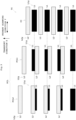
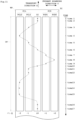
- Figs. 3 - 5 are schematic views showing a middle chart and part of one-side peripheral charts of a shift amount detecting chart.
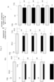
- Figs. 6 - 8 are schematic views showing the middle chart and part of other side peripheral charts of the shift amount detecting chart.
- a shift amount detecting chart TC includes a middle chart CC formed in a middle portion in the primary scanning direction Y
- One-side peripheral charts PCL are formed on a left side which is one side of the middle chart CC in the primary scanning direction Y
- Other side peripheral charts PCR are formed on a right side which is the other side of the middle chart CC in the primary scanning direction Y.
- two one-side peripheral charts PCL first one-side peripheral chart PCL1 and second one-side peripheral chart PCL2
- two other side peripheral charts PCR first other side peripheral chart PCR1 and second other side peripheral chart PCR2
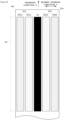
- the shift amount detecting chart TC is formed over the predetermined length LN in the transport direction X.
- the middle chart CC includes a first line segment group L1g having a plurality of first line segments L1 formed, and a second line segment group L2g having a plurality of second line segments L2 formed.
- the first line segment group L1g is formed by a print head 19 acting as printing reference, e.g. the print head 19a.
- the second line segment group L2g is printed by the print head 19b which is different from the print head 19a acting as reference.
- the first line segment group L1g of the middle chart CC has the first line segments L1 with long sides in the primary scanning direction Y and short sides in the transport direction X, which are formed at predetermined constant intervals in the transport direction X.
- the middle chart CC includes the second line segments L2 with long sides longer than the first line segments L1 and short sides slightly shorter than the short sides of the first line segments L1, which are formed and arranged in the middle between the first line segments L1 in the transport direction X.
- the above print head 19a corresponds to the "reference print head” in this invention.
- the print head 19b corresponds to the "objective print head” in this invention.
- the first one-side peripheral chart PCL1 and second one-side peripheral chart PCL2 are formed to be spaced leftward in the primary scanning direction Y from the middle chart CC, and also to be spaced from each other in the primary scanning direction Y.
- the first one-side peripheral chart PCL1 and second one-side peripheral chart PCL2 have first line segment groups L1g formed in the same positions in the transport direction X as the first line segment group L1g of the middle chart CC.
- the first one-side peripheral chart PCL1 and second one-side peripheral chart PCL2 have second line segment groups L2g which, however, are formed in positions different between the first one-side peripheral chart PCL1 and second one-side peripheral chart PCL2.
- the first one-side peripheral chart PCL1 close to the middle chart CC has the second line segments L2 formed at wider intervals downstream in the transport direction X from the first line segments L1 than the intervals between the first line segments L1 and second line segments L2 of the middle chart CC.
- the second one-side peripheral chart PCL2 far from the middle chart CC has the second line segments L2 formed at wider intervals downstream in the transport direction X from the first line segments L1 than the intervals between the first line segments L1 and second line segments L2 of the first one-side peripheral chart PCL1.
- the one-side peripheral charts PCL have the first line segments L1 and the second line segments L2 downstream thereof formed at intervals gradually widening, progressively toward an end of the one side in the primary scanning direction Y from the middle chart CC.
- the first other side peripheral chart PCR1 and second other side peripheral chart PCR2 are formed to be spaced rightward in the primary scanning direction Y from the middle chart CC, and also to be spaced from each other in the primary scanning direction Y.
- the first other side peripheral chart PCR1 and second other side peripheral chart PCR2 are different from the first one-side peripheral chart PCL1 and second one-side peripheral chart PCL2 in that second line segments L2 located downstream in the transport direction X from first line segments L1 have reduced intervals relative to the first line segments L1.
- the first other side peripheral chart PCR1 close to the middle chart CC has the second line segments L2 formed at narrower intervals downstream in the transport direction X from the first line segments L1 than the intervals between the first line segments L1 and second line segments L2 of the middle chart CC.
- the second other side peripheral chart PCR2 far from the middle chart CC has the second line segments L2 formed at narrower intervals downstream in the transport direction X from the first line segments L1 than the intervals between the first line segments L1 and second line segments L2 of the first other side peripheral chart PCR1.
- the other side peripheral charts PCR have the first line segments L1 and the second line segments L2 downstream thereof formed at intervals gradually narrowing, progressively toward an end of the other side in the primary scanning direction Y from the middle chart CC,
- Fig. 4 shows the middle chart CC, first one-side peripheral chart PCL1, and second one-side peripheral chart PCL2, which is a figure for particularly describing the first line segment groups L1g in detail.
- the first line segment group L1g of the middle chart CC consists of a plurality of first line segments L1. These first line segments L1 are formed by the head module HMc located in the middle in the primary scanning direction of the print head 19a which dispenses K color ink, The plurality of first line segments L1 of the middle chart CC are spaced from one another at uniform centerline intervals d1 in the transport direction X.
- the first line segment group L1g of the first one-side peripheral chart PCL1 consists of a plurality of first line segments L1. These first line segments L1 are formed by driving the head module HMb in the print head 19a which dispenses K color ink, with the same timing as the head module HMc.
- the plurality of first line segments L1 of the first one-side peripheral chart PCL1 are spaced from one another at uniform centerline intervals d1 in the transport direction X.
- the first line segment group L1g of the second one-side peripheral chart PCL2 consists of a plurality of first line segments L1. These first line segments L1 are formed by driving the head module HMa in the print head 19a which dispenses K color ink, with the same timing as the head modules HMc and HMb.
- the plurality of first line segments L1 of the second one-side peripheral chart PCL2 are spaced from one another at uniform centerline intervals d1 in the transport direction X.
- Fig. 5 shows the middle chart CC, first one-side peripheral chart PCL1, and second one-side peripheral chart PCL2, which is a figure for particularly describing the second line segment groups L2g in detail.
- the second line segment group L2g of the middle chart CC consists of a plurality of second line segments L2. These second line segments L2 are formed by the head module HMc located in the middle in the primary scanning direction of the print head 19c which dispenses C color ink, The plurality of second line segments L2 of the middle chart CC are spaced from one another at uniform centerline intervals d2 in the transport direction X. Note that the centerline intervals d2 of the second line segment group L2g are the same in length as the above-mentioned centerline intervals d1 of the first line segment group L1g.
- the second line segment group L2g of the first one-side peripheral chart PCL1 consists of a plurality of second line segments L2. These second line segments L2 are formed by the head module HMb in the print head 19c which dispenses C color ink.
- the plurality of second line segments L2 of the first one-side peripheral chart PCL1 are spaced from one another at uniform centerline intervals d2 in the transport direction X.
- the head module HMb of the print head 19c begins to be driven in advance by advance time t1 of the head module HMc of the print head 19c.
- the second line segment group L2g of the first one-side peripheral chart PCL1 is formed as shifted by distance ⁇ d1 downstream in the transport direction X from the second line segment group L2g of the middle chart CC.
- the second line segment group L2g of the second one-side peripheral chart PCL2 consists of a plurality of second line segments L2. These second line segments L2 are formed by the head module HMa in the print head 19c which dispenses C color ink.
- the plurality of second line segments L2 of the second one-side peripheral chart PCL2 are spaced from one another at uniform centerline intervals d2 in the transport direction X.
- the head module HMa of the print head 19c begins to be driven in advance by advance time t2 of the head module HMb of the print head 19c.
- the second line segment group L2g of the second one-side peripheral chart PCL2 is formed as shifted by distance ⁇ d2 downstream in the transport direction X from the second line segment group L2g of the first one-side peripheral chart PCL1.
- advance time t1 of the head module HMb relative to the head module HMc of the print head 19c is the same as advance time t2 of the head module HMa relative to the head module HMb of the print head 19c. Therefore, the above-mentioned distance ⁇ d1 and distance ⁇ d2 are the same in length.
- each first line segment L1 of the middle chart CC is located exactly in the middle between an adjacent pair of second line segments L2.
- each second line segment L2 of the first one-side peripheral chart PCL1 is formed as shifted by distance ⁇ d1 downstream in the transport direction X from the middle position of the second line segment L2 adjoining in the primary scanning direction Y
- each second line segment L2 of the second one-side peripheral chart PCL2 is formed as further shifted by distance ⁇ d2 downstream in the transport direction X from the middle position of the second line segment L2 adjoining in the primary scanning direction Y
- Fig. 7 shows the middle chart CC and first other side peripheral chart PCR1, and second other side peripheral chart PCR2, which is a figure for particularly describing the first line segment groups L1g in detail.
- the plurality of first line segments L1 constituting the first line segment group L1g of the middle chart CC are spaced from one another at uniform centerline intervals d1 in the transport direction X as described hereinbefore.
- the first line segment group L1g of the first other side peripheral chart PCR1 consists of a plurality of first line segments L1. These first line segments L1 are formed by driving the head module HMd in the print head 19a which dispenses K color ink, with the same timing as the head module HMc.
- the plurality of first line segments L1 of the first other side peripheral chart PCR1 are spaced from one another at uniform centerline intervals d1 in the transport direction X.
- the first line segment group L1g of the second other side chart PCR2 consists of a plurality of first line segments L1. These first line segments L1 are formed by driving the head module HMe in the print head 19a which dispenses K color ink, with the same timing as the head modules HMc and HMd.
- the plurality of first line segments L1 of the second other side chart PCR2 are spaced from one another at uniform centerline intervals d1 in the transport direction X.
- Fig. 8 shows the middle chart CC and first other side peripheral chart PCR1, and second other side peripheral chart PCR2, which is a figure for particularly describing the second line segment groups L2g in detail.
- the plurality of second line segments L2 of the middle chart CC are spaced from one another at uniform centerline intervals d2 in the transport direction X.
- the intervals d2 of the second line segment group L2g are the same in length as the intervals of the first line segment group L1g noted hereinbefore.
- the second line segment group L2g of the first other side peripheral chart PCR1 consists of a plurality of second line segments L2. These second line segments L2 are formed by the head module HMd in the print head 19c which dispenses C color ink.
- the plurality of second line segments L2 of the first other side chart PCR1 are spaced from one another at uniform centerline intervals d2 in the transport direction X.
- the head module HMd of the print head 19c begins to be driven later by delay time t3 than the head module HMc of the print head 19c.
- the second line segment group L2g of the first other side peripheral chart PCR1 is formed as shifted by distance ⁇ d3 upstream in the transport direction X from the second line segment group L2g of the middle chart CC.
- the second line segment group L2g of the second other side peripheral chart PCR2 consists of a plurality of second line segments L2. These second line segments L2 are formed by the head module HMe in the print head 19c which dispenses C color ink.
- the plurality of second line segments L2 of the second other side peripheral chart PCR2 are spaced from one another at uniform centerline intervals d2.
- the head module HMa of the print head 19c begins to be driven later by delay time t4 than the head module HMb of the print head 19c.
- the second line segment group L2g of the second other side peripheral chart PCR2 is formed as shifted by distance ⁇ d4 upstream in the transport direction X from the second line segment group L2g of the first other side peripheral chart PCR1.
- the delay time t3 of the head module HMd relative to the head module HMc of the print head 19c is the same as the delay time t4 of the head module HMe relative to the head module HMd of print head 19c. Therefore, distance ⁇ d3 and distance ⁇ d4 are the same in length.
- each second line segment L2 of the first other side peripheral chart PCR1 is formed as shifted by distance ⁇ d3 upstream in the transport direction X from the middle position of the second line segment L2 adjoining in the primary scanning direction Y
- each second line segment L2 of the second other side peripheral chart PCR2 is formed as further shifted by distance ⁇ d4 upstream in the transport direction X from the middle position of the second line segment L2 adjoining in the primary scanning direction Y.
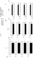
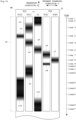
- Fig. 9 is a schematic view showing the shift amount detecting chart TC printed on the web paper WP in a state where ideal conditions continue.
- the results may be the shift amount detecting chart TC shown in Fig. 9 , for example. That is, the middle chart CC, since there is no overlap of the first line segments L1 and second line segments L2, has the color of the second line segments L2 in the densest color thereof, which is the color of cyan (C) in this example. Especially since the length of the long sides of the second line segments L2 is formed longer than the long sides of the first line segments L1, the density of cyan (C) can be formed in increased density.
- the first line segments L1 in black (K) overlap the second line segments L2 in cyan (C) in increasing degrees toward the peripheral areas in the primary scanning direction Y, and this reduces the color of cyan (C) and makes the color of black (K) densest.
- the middle chart CC is the smallest, the next are the first one-side peripheral chart PCL1 and first other side peripheral chart PCR1, and the second next are the second one-side peripheral chart PCL2 and second other side peripheral chart PCR2. Consequently, when seen macroscopically, the shift amount detecting chart TC printed under ideal conditions has the middle chart CC with the highest density, the first one-side peripheral chart PCL1 and first other side peripheral chart PCR1 with a density lower than that, and the second one-side peripheral chart PCL2 and second other side peripheral chart PCR2 with a still lower density.
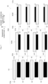
- the shift amount detecting chart TC becomes as shown in Fig. 10 , for example.
- Fig. 10 since cyan (C) cannot be expressed, the areas where cyan (C) becomes dense are expressed in black, and the areas where cyan (C) becomes pale are expressed in white. The density peak positions where cyan (C) becomes the densest are expressed in the densest black.
- the transporting speed may be changed by various causes.
- the transporting speed of the web paper WP deviating from the transporting speed in the ideal conditions may cause deteriorations in print quality (specifically, phenomena called level difference gap and color shift).
- It is necessary to alleviate the 18 variations of the transporting speed by correcting the dispensation timing of the objective print head (print head 19b) relative to the reference print head (print head 19a).
- a correction value for the print head 19b is calculated by reading the shift amount detecting chart TC as shown in Fig. 10 , and analyzing the read image.
- a plurality of high density areas r1-r11 have occurred in the shift amount detecting chart TC.
- a time axis TIME is added to the shift amount detecting chart TC to indicate approximate times at each the areas r1-r11 are printed. That is, area r1 is printed around times 1 and 2, area r2 around time 3, and area r3 around time 4.
- Area r4 is printed around time 5, area r5 around time 6, area r6 around time 7, area r7 around time 8, area r8 around times 9 and 10, area r9 around times 11 and 12, area r10 around times 13 to 15, and area r 11 around times 16 and 17.
- the variations in the transporting speed of the web paper WP can be guessed as follows by analyzing the shift amount detecting chart TC. For example, in a time section from time 1 to time 2, the density of area r1 of the middle chart CC is higher than the density of the one-side peripheral charts PCL1 and PCL2 and the other side peripheral charts PCR1 and PCR2. It is therefore thought that, in this time section, the web paper WP is transported at the transporting speed in the ideal conditions.
- the transporting speed of the web paper WP is considered to increase gradually from the ideal transporting speed. That is, when the transporting speed of the web paper WP gradually increases from the ideal transporting speed, the position of the first line segment group L1g relative to the second line segment group L2g shifts downstream in the transport direction X. As a result, the blank areas of the middle chart CC gradually increase (the density lowers), and the blank areas of the first one-side peripheral chart PCL1 gradually decrease (the density rises).
- the density of the second one-side peripheral chart PCL2 is the highest (area r3). It is thought that, in this state, the first line segment group L1g is located in substantially the middle of the blank areas of the second one-side peripheral chart PCL2.
- This embodiment assumes that the density peak position where cyan (C) is the densest moves from the middle chart CC to the one-side peripheral chart PCL1, one-side peripheral chart PCL2, one-side peripheral chart PCL1, middle chart CC, other side peripheral chart PCR1, other side peripheral chart PCR2, other side peripheral chart PCR1, one-side peripheral chart PCL1, one-side peripheral chart PCL2, and middle peripheral chart CC.
- Each of the shift amounts -1, -2, +1 and +2 is determined beforehand to correspond to a specific shift amount unit (e.g. 0.25 ⁇ m) for each inkjet printing apparatus 3.
- the image processor 27 carries out image processing of image data corresponding to the shift amount detecting chart TC of Fig. 10 .
- a variation trace of the density peak position where cyan (C) is the densest in the primary scanning direction Y within the predetermined length LN is determined.
- density peak positions in the transport direction X are in values as indicated by "x" marks in Fig. 11 , it is preferable, for example, to carry out a smoothing process of graphs on a polygonal line connecting the density peak positions to create a curved variation trace.
- the image processor 27 calculates a frequency distribution of shift amounts by dividing at predetermined intervals in the transport direction X, the curve showing the variation trace of the density peak positions as shown in Fig. 7 .
- the image processor 27 creates a frequency distribution table based on Fig. 11 . Assume, for example, that a frequency distribution table as shown in Fig. 12 is obtained. The frequency is the highest at the time of shift amount ⁇ 0, and then frequencies line up in the order of shift amounts -2, -1, +1, and +2. The image processor 27 can calculate correction values based on the frequency distribution table.
- a negative correction value is a correction value for adjusting (advancing) the ink dispensation timing of the print head 19b to move the density peak positions rightward in the primary scanning direction in the shift amount detecting chart TC.
- the positive correction values are correction values for adjusting (delaying) the ink dispensation timing of the print head 19b to move the density peak positions leftward in the primary scanning direction in the shift amount detecting chart TC.
- correction value +1 is determined to be the correction value applied to areas r1-r5.
- Fig. 13 is a graph showing frequency versus intensity in the graph of Fig. 11 .
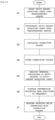
- Fig. 14 is a flow chart showing an example of processing sequence in the embodiment.
- the controller 25 operates the drive rollers 7 and 11, and drive boards 35 to print the shift amount detecting chart TC described above, with the print heads 19 over the predetermined length LN of the web paper WP.
- Step S2 (imaging step)
- the controller 25 operates the image pickup unit 17 to photograph the shift amount detecting chart TC printed on the web paper WP, and collect image data corresponding to the shift amount detecting chart TC.
- the image data corresponding to the shift amount detecting chart TC is given to the image processor 27.
- Step S3 correction value calculating step
- the image processor 27 determines a variation trace of density peak positions based on the image data corresponding to the shift amount detecting chart TC.
- the image processor 27 calculates correction values based on the techniques described above and based on the variation trace.
- Step S4 correction value storing step
- Step S5 extracting step
- Step S6 output step
- the analysis unit 29 outputs to and displays on the display unit 31 the information including the peak positions of the frequency in the frequency versus intensity extracted in step S5.
- the operator of the inkjet printing system may look at the display on the display unit 31, and take countermeasures to a cause of temporal variations of the shift amounts.
- the shift amount detecting chart TC is formed on the web paper WP transported by the drive rollers 9 and 11 and transport rollers 9, and the shift amount detecting chart TC is photographed by the image pickup unit 17.
- the size and cycle of temporal variations of the shift amounts vary from each individual to another of the inkjet printing apparatus 3. Then, one cycle of temporal variations of the shift amounts may be measured beforehand, and the shift amount detecting chart TC may be formed on the web paper WP covering the predetermined length LN which corresponds to the cycle. Thus, the correction values can be calculated appropriately.
- this invention is suitable for a printing apparatus and a printing method for performing printing with a plurality of print heads arranged at intervals in a transport direction of a printing medium.
Landscapes
- Engineering & Computer Science (AREA)
- Quality & Reliability (AREA)
- Ink Jet (AREA)
Claims (10)
- Druckvorrichtung (3) zum Drucken auf ein Druckmedium (WP), umfassend:eine Transporteinrichtung (9, 11), die eingerichtet ist, das Druckmedium in einer Transportrichtung (X) zu transportieren;eine Vielzahl von Druckköpfen (19), die getrennt in der Transportrichtung angeordnet sind und eingerichtet sind, das Druckmedium (WP) zu bedrucken;eine Verschiebungsbetragserfassungsdiagrammerzeugungseinrichtung (25), die eingerichtet ist, ein Verschiebungsbetragserfassungsdiagramm (TC) auf dem Druckmedium (WP) zu bilden, wobei das Verschiebungsbetragserfassungsdiagramm (TC) umfasst:• ein mittleres Diagramm (CC), das in einem mittleren Abschnitt des Druckmediums (WP) in einer primären Scanrichtung (Y) senkrecht zu der Transportrichtung (X) gedruckt wird, und aufweist:eine erste Liniensegmentgruppe (L1g) aus ersten Liniensegmenten (L1), die, in konstanten Abständen über eine vorbestimmte Länge in der Transportrichtung (X) angeordnet und eine lange Seite in der primären Scanrichtung (Y) aufweisend, durch einen Referenzdruckkopf (19a) gebildet werden, der als Referenzposition in der Transportrichtung (X) unter der Vielzahl von Druckköpfen (19) dient, undeine zweite Liniensegmentgruppe (L2g) aus zweiten Liniensegmenten (L2), die durch einen Objektivdruckkopf (19b), der in der Transportrichtung (X) getrennt von dem Referenzdruckkopf (19a) unter der Vielzahl von Druckköpfen (19) platziert ist, derart gebildet werden, dass diese eine lange Seite in der primären Scanrichtung (Y) aufweisen, und sich in einer Mitte in der Transportrichtung (X) zwischen den ersten Liniensegmenten (L1) oder an Zentren in der Transportrichtung (X) der ersten Liniensegmente (L1) befinden;• Peripheriediagramme einer Seite (PCL), die getrennt auf einer Seite in der primären Scanrichtung von dem mittleren Diagramm (CC) gebildet werden, wobei sich die Abstände in der Transportrichtung (X) der ersten Liniensegmente (L1) und der zweiten Liniensegmente (L2) in dem mittleren Diagramm (CC) graduell erweitern, und zwar progressiv zum Ende hin in der primären Scanrichtung (Y); und• Peripheriediagramm einer anderen Seite (PCR), die getrennt auf der anderen Seite in der primären Scanrichtung (Y) von der Richtung des mittleren Diagramms gebildet werden, wobei sich die Abstände in der Transportrichtung der ersten Liniensegmente (L1) und der zweiten Liniensegmente (L2) in dem mittleren Diagramm graduell verengen, und zwar progressiv zum Ende hin in der primären Scanrichtung (Y);eine Bildaufnahmeeinrichtung (17), die eingerichtet ist, das auf das Druckmedium (WP) gedruckte Verschiebungsbetragserfassungsdiagramm (TC) zu fotografieren;eine Berechnungseinrichtung (27), die, unter Bezugnahme auf die Diagramme des Verschiebungsbetragserfassungsdiagramms (TC), die von der Bildaufnahmeeinrichtung (17) fotografiert wurden, und basierend auf einer Variationskurve von Dichtepeakpositionen in den Diagrammen des Verschiebungsbetragserfassungsdiagramms (TC) in der primären Scanrichtung (Y) innerhalb der vorbestimmten Länge (LN), eingerichtet ist, Korrekturwerte aus Verschiebungsbeträgen zu berechnen, die kleiner als ein maximaler Verschiebungsbetrag in absoluten Werten in den Diagrammen des Verschiebungsbetragserfassungsdiagramms (TC) sind; undeine Korrektureinrichtung (25), die eingerichtet ist, die Druckzeit des Objektivdruckkopfes (19b) relativ zu dem Referenzdruckkopf (19a) mit den Korrekturwerten zu korrigieren.
- Druckvorrichtung (3) gemäß Anspruch 1, wobei die Berechnungseinrichtung (27) eingerichtet ist, die Korrekturwerte basierend auf einer Auftretungshäufigkeit der Verschiebungsbeträge zu bestimmen.
- Druckvorrichtung (3) gemäß Anspruch 1, wobei die Berechnungseinrichtung (27) eingerichtet ist, die Korrekturwerte derart zu bestimmen, dass die Gesamtsumme der Verschiebungsbeträge nach der Korrektur minimiert wird.
- Druckvorrichtung (3) gemäß einem der Ansprüche 1 bis 3, ferner umfassend:eine Extraktionseinrichtung (29), die eingerichtet ist, eine Häufigkeit gegen eine Intensität der Dichtepeakpositionen in der vorbestimmten Länge (LN) um das Verschiebungsbetragserfassungsdiagramm (TC) zu extrahieren; undeine Ausgabeeinrichtung, die eingerichtet ist, Informationen einschließlich der Peakpositionen der Häufigkeit auszugeben.
- Druckvorrichtung (3) gemäß einem der Ansprüche 1 bis 4, wobei die vorgegebene Länge einem Durchlauf der zuvor gemessenen zeitlichen Variationen der Verschiebungsbeträge entspricht.
- Druckverfahren zum Drucken auf ein Druckmedium (WP), umfassend:einen Bildungsschritt eines Verschiebungsbetragserfassungsdiagramms (TC) zum Bilden eines Verschiebungsbetragserfassungsdiagramms (TC) auf dem Druckmedium (WP), wobei das Verschiebungsbetragserfassungsdiagramm (TC) umfasst:ein mittleres Diagramm (CC), das in einem mittleren Abschnitt des Druckmediums (WP) in einer primären Scanrichtung (Y) senkrecht zu der Transportrichtung (X) gedruckt wird, und aufweist:eine erste Liniensegmentgruppe (L1g) aus ersten Liniensegmenten (L1), die, in konstanten Abständen über eine vorbestimmte Länge in der Transportrichtung (X) angeordnet und eine lange Seite in der primären Scanrichtung (Y) aufweisend, durch einen Referenzdruckkopf (19a) gebildet werden, der als Referenzposition in der Transportrichtung (X) unter einer Vielzahl von Druckköpfen (19), die getrennt in der Transportrichtung (X) zum Drucken auf das Druckmedium (WP) angeordnet sind, dient, undeine zweite Liniensegmentgruppe (L2g) aus zweiten Liniensegmenten (L2), die durch einen Objektivdruckkopf (19b), der in der Transportrichtung (X) getrennt von dem Referenzdruckkopf (19a) unter der Vielzahl von Druckköpfen (19) platziert ist, derart gebildet werden, dass diese eine lange Seite in der primären Scanrichtung (Y) aufweisen, und sich in einer Mitte in der Transportrichtung (X) zwischen den ersten Liniensegmenten (L1) oder an Zentren in der Transportrichtung (X) der ersten Liniensegmente (L1) befinden;Peripheriediagramme einer Seite (PCL), die getrennt auf einer Seite in der primären Scanrichtung von dem mittleren Diagramm (CC) gebildet werden, wobei sich die Abstände in der Transportrichtung (X) der ersten Liniensegmente (L1) und der zweiten Liniensegmente (L2) in dem mittleren Diagramm (CC) graduell erweitern, und zwar progressiv zum Ende hin in der primären Scanrichtung (Y); undPeripheriediagramm einer anderen Seite (PCR), die getrennt auf der anderen Seite in der primären Scanrichtung (Y) von der Richtung des mittleren Diagramms gebildet werden, wobei sich die Abstände in der Transportrichtung der ersten Liniensegmente (L1) und der zweiten Liniensegmente (L2) in dem mittleren Diagramm graduell verengen, und zwar progressiv zum Ende hin in der primären Scanrichtung (Y);einen Bildaufnahmeschritt des Fotografierens des auf das Druckmedium (WP) gedruckten Verschiebungsbetragserfassungsdiagramms (TC);einen Korrekturwertberechnungsschritt zur Berechnung, unter Bezugnahme auf die Diagramme des Verschiebungsbetrags-Erfassungsdiagramms (TC), die durch die Bildaufnahmeeinrichtung (17) fotografiert werden, und basierend auf einer Variationskurve von Dichtepeakpositionen in den Diagrammen des Verschiebungsbetragserfassungsdiagramms (TC) in der primären Scanrichtung (Y) innerhalb der vorbestimmten Länge (LN), von Korrekturwerten aus Verschiebungsbeträgen, die kleiner als ein maximaler Verschiebungsbetrag in absoluten Werten in dem Verschiebungsbetragserfassungsdiagramm (TC) sind; undeinen Korrekturschritt des Korrigierens des Druckzeitpunkts des Objektivdruckkopfes (19b) relativ zu dem Referenzdruckkopf (19a) mit den Korrekturwerten.
- Druckverfahren gemäß Anspruch 6, wobei der Korrekturwertberechnungsschritt ausgeführt wird, um die Korrekturwerte basierend auf einer Auftretungshäufigkeit der Verschiebungsbeträge zu bestimmen.
- Druckverfahren gemäß Anspruch 6, wobei der Korrekturwertberechnungsschritt ausgeführt wird, um die Korrekturwerte derart zu bestimmen, dass die Gesamtsumme der Verschiebungsbeträge nach der Korrektur minimiert wird.
- Druckverfahren gemäß einem der Ansprüche 6 bis 8, ferner umfassend:einen Extraktionsschritt des Extrahierens einer Häufigkeit gegen eine Intensität der Dichtepeakpositionen in der vorbestimmten Länge um das Verschiebungsbetragserfassungsdiagramm; undeinen Ausgabeschritt der Ausgabe von Informationen einschließlich der Peakpositionen der Häufigkeit.
- Druckverfahren gemäß einem der Ansprüche 6 bis 9, wobei die vorgegebene Länge einem Durchlauf der zuvor gemessenen zeitlichen Variationen der Verschiebungsbeträge entspricht.
Applications Claiming Priority (2)
| Application Number | Priority Date | Filing Date | Title |
|---|---|---|---|
| JP2019176994A JP7221185B2 (ja) | 2019-09-27 | 2019-09-27 | 印刷装置及び印刷方法 |
| PCT/JP2020/024379 WO2021059627A1 (ja) | 2019-09-27 | 2020-06-22 | 印刷装置及び印刷方法 |
Publications (3)
| Publication Number | Publication Date |
|---|---|
| EP4035900A1 EP4035900A1 (de) | 2022-08-03 |
| EP4035900A4 EP4035900A4 (de) | 2023-09-20 |
| EP4035900B1 true EP4035900B1 (de) | 2025-01-22 |
Family
ID=75166907
Family Applications (1)
| Application Number | Title | Priority Date | Filing Date |
|---|---|---|---|
| EP20868474.6A Active EP4035900B1 (de) | 2019-09-27 | 2020-06-22 | Druckvorrichtung und druckverfahren |
Country Status (4)
| Country | Link |
|---|---|
| US (1) | US12043024B2 (de) |
| EP (1) | EP4035900B1 (de) |
| JP (1) | JP7221185B2 (de) |
| WO (1) | WO2021059627A1 (de) |
Families Citing this family (2)
| Publication number | Priority date | Publication date | Assignee | Title |
|---|---|---|---|---|
| JP7739819B2 (ja) * | 2021-07-29 | 2025-09-17 | ブラザー工業株式会社 | 印刷装置 |
| JP2024051459A (ja) | 2022-09-30 | 2024-04-11 | セイコーエプソン株式会社 | 記録装置および記録方法 |
Family Cites Families (11)
| Publication number | Priority date | Publication date | Assignee | Title |
|---|---|---|---|---|
| JP2000035704A (ja) * | 1998-07-17 | 2000-02-02 | Canon Inc | 画像形成装置および画像形成装置の色ずれ補正方法 |
| JP2001162912A (ja) * | 1999-12-10 | 2001-06-19 | Fuji Xerox Co Ltd | 画像ずれ補正方法および画像形成装置 |
| US7350892B2 (en) * | 2004-12-17 | 2008-04-01 | Hewlett-Packard Development Company, L.P. | Printing system and method of printing an image in a fixed head printing system |
| JP4760476B2 (ja) * | 2006-03-28 | 2011-08-31 | ブラザー工業株式会社 | 画像形成装置及びずれ量検出方法 |
| JP5004335B2 (ja) * | 2007-02-02 | 2012-08-22 | キヤノン株式会社 | 記録位置調整方法、記録システム、ホスト装置及びプログラム |
| US8136903B2 (en) | 2008-08-08 | 2012-03-20 | Canon Kabushiki Kaisha | Ink jet printing apparatus and ink jet printing method |
| US10143260B2 (en) | 2014-02-21 | 2018-12-04 | Nike, Inc. | Article of footwear incorporating a knitted component with durable water repellant properties |
| JP6282912B2 (ja) | 2014-03-25 | 2018-02-21 | 株式会社Screenホールディングス | 検査用チャート及び印刷装置 |
| JP6900409B2 (ja) | 2015-03-27 | 2021-07-07 | 株式会社Screenホールディングス | 印刷装置 |
| JP6480231B2 (ja) | 2015-03-27 | 2019-03-06 | 株式会社Screenホールディングス | 印刷装置 |
| JP7119404B2 (ja) * | 2018-02-13 | 2022-08-17 | コニカミノルタ株式会社 | 画像データ処理方法、画像データ処理装置及びインクジェット記録装置 |
-
2019
- 2019-09-27 JP JP2019176994A patent/JP7221185B2/ja active Active
-
2020
- 2020-06-22 US US17/637,187 patent/US12043024B2/en active Active
- 2020-06-22 WO PCT/JP2020/024379 patent/WO2021059627A1/ja not_active Ceased
- 2020-06-22 EP EP20868474.6A patent/EP4035900B1/de active Active
Also Published As
| Publication number | Publication date |
|---|---|
| US12043024B2 (en) | 2024-07-23 |
| US20220297447A1 (en) | 2022-09-22 |
| EP4035900A1 (de) | 2022-08-03 |
| JP2021053839A (ja) | 2021-04-08 |
| EP4035900A4 (de) | 2023-09-20 |
| JP7221185B2 (ja) | 2023-02-13 |
| WO2021059627A1 (ja) | 2021-04-01 |
Similar Documents
| Publication | Publication Date | Title |
|---|---|---|
| US12001902B2 (en) | Correcting distortions in digital printing by implanting dummy pixels in a digital image | |
| US20190152218A1 (en) | Correcting Distortions in Digital Printing | |
| US8842330B1 (en) | Method to determine an alignment errors in image data and performing in-track alignment errors correction using test pattern | |
| EP3305532A1 (de) | Bildinspektionsvorrichtung, bildinspektionsverfahren, programm und tintenstrahldrucksystem | |
| US8842331B1 (en) | Multi-print head printer for detecting alignment errors and aligning image data reducing swath boundaries | |
| US8857938B2 (en) | Aligning print data for overlapping printheads | |
| US10343433B2 (en) | Skew sensor calibration | |
| US20150116734A1 (en) | Printer with image plane alignment correction | |
| US10800193B2 (en) | Nozzle operating situation checking method for inkjet printing apparatus, an inkjet printing apparatus, and a program thereof | |
| EP4035900B1 (de) | Druckvorrichtung und druckverfahren | |
| US20200165088A1 (en) | Image reading apparatus and image forming system | |
| US20150116735A1 (en) | Printer with feedback correction of image displacements | |
| JP5323555B2 (ja) | 印刷システムおよび印刷方法 | |
| JP7323406B2 (ja) | 印刷装置 | |
| US20150116736A1 (en) | Printer with feedback correction of image plane alignment | |
| US8845059B2 (en) | Aligning print data using matching pixel patterns | |
| JP7225977B2 (ja) | 画像形成装置 | |
| US11573749B2 (en) | Image forming apparatus and method for controlling image forming apparatus | |
| US9757967B2 (en) | Testing chart, a correction value acquiring method for an inkjet printing apparatus, and an inkjet printing apparatus | |
| US9452603B1 (en) | Printing apparatus | |
| US20180239997A1 (en) | Printing apparatus and printing method | |
| JP6151595B2 (ja) | インクジェット印刷装置及びその段差ずれ補正方法 | |
| CN119276988A (zh) | 图像形成控制方法以及图像形成装置 | |
| JP2019069625A (ja) | 印刷装置 | |
| JP7289683B2 (ja) | 印刷装置及びその印刷方法 |
Legal Events
| Date | Code | Title | Description |
|---|---|---|---|
| STAA | Information on the status of an ep patent application or granted ep patent |
Free format text: STATUS: THE INTERNATIONAL PUBLICATION HAS BEEN MADE |
|
| PUAI | Public reference made under article 153(3) epc to a published international application that has entered the european phase |
Free format text: ORIGINAL CODE: 0009012 |
|
| STAA | Information on the status of an ep patent application or granted ep patent |
Free format text: STATUS: REQUEST FOR EXAMINATION WAS MADE |
|
| 17P | Request for examination filed |
Effective date: 20220331 |
|
| AK | Designated contracting states |
Kind code of ref document: A1 Designated state(s): AL AT BE BG CH CY CZ DE DK EE ES FI FR GB GR HR HU IE IS IT LI LT LU LV MC MK MT NL NO PL PT RO RS SE SI SK SM TR |
|
| DAV | Request for validation of the european patent (deleted) | ||
| DAX | Request for extension of the european patent (deleted) | ||
| A4 | Supplementary search report drawn up and despatched |
Effective date: 20230823 |
|
| RIC1 | Information provided on ipc code assigned before grant |
Ipc: B41J 11/00 20060101ALI20230817BHEP Ipc: B41J 2/21 20060101ALI20230817BHEP Ipc: B41J 2/01 20060101AFI20230817BHEP |
|
| GRAP | Despatch of communication of intention to grant a patent |
Free format text: ORIGINAL CODE: EPIDOSNIGR1 |
|
| STAA | Information on the status of an ep patent application or granted ep patent |
Free format text: STATUS: GRANT OF PATENT IS INTENDED |
|
| INTG | Intention to grant announced |
Effective date: 20240827 |
|
| GRAS | Grant fee paid |
Free format text: ORIGINAL CODE: EPIDOSNIGR3 |
|
| GRAA | (expected) grant |
Free format text: ORIGINAL CODE: 0009210 |
|
| STAA | Information on the status of an ep patent application or granted ep patent |
Free format text: STATUS: THE PATENT HAS BEEN GRANTED |
|
| AK | Designated contracting states |
Kind code of ref document: B1 Designated state(s): AL AT BE BG CH CY CZ DE DK EE ES FI FR GB GR HR HU IE IS IT LI LT LU LV MC MK MT NL NO PL PT RO RS SE SI SK SM TR |
|
| REG | Reference to a national code |
Ref country code: GB Ref legal event code: FG4D |
|
| REG | Reference to a national code |
Ref country code: CH Ref legal event code: EP |
|
| REG | Reference to a national code |
Ref country code: IE Ref legal event code: FG4D |
|
| REG | Reference to a national code |
Ref country code: DE Ref legal event code: R096 Ref document number: 602020045311 Country of ref document: DE |
|
| P01 | Opt-out of the competence of the unified patent court (upc) registered |
Free format text: CASE NUMBER: APP_3303/2025 Effective date: 20250121 |
|
| P02 | Opt-out of the competence of the unified patent court (upc) changed |
Free format text: CASE NUMBER: APP_4665/2025 Effective date: 20250128 |
|
| REG | Reference to a national code |
Ref country code: NL Ref legal event code: MP Effective date: 20250122 |
|
| PG25 | Lapsed in a contracting state [announced via postgrant information from national office to epo] |
Ref country code: NL Free format text: LAPSE BECAUSE OF FAILURE TO SUBMIT A TRANSLATION OF THE DESCRIPTION OR TO PAY THE FEE WITHIN THE PRESCRIBED TIME-LIMIT Effective date: 20250122 |
|
| PG25 | Lapsed in a contracting state [announced via postgrant information from national office to epo] |
Ref country code: RS Free format text: LAPSE BECAUSE OF FAILURE TO SUBMIT A TRANSLATION OF THE DESCRIPTION OR TO PAY THE FEE WITHIN THE PRESCRIBED TIME-LIMIT Effective date: 20250422 |
|
| PG25 | Lapsed in a contracting state [announced via postgrant information from national office to epo] |
Ref country code: FI Free format text: LAPSE BECAUSE OF FAILURE TO SUBMIT A TRANSLATION OF THE DESCRIPTION OR TO PAY THE FEE WITHIN THE PRESCRIBED TIME-LIMIT Effective date: 20250122 |
|
| PG25 | Lapsed in a contracting state [announced via postgrant information from national office to epo] |
Ref country code: PL Free format text: LAPSE BECAUSE OF FAILURE TO SUBMIT A TRANSLATION OF THE DESCRIPTION OR TO PAY THE FEE WITHIN THE PRESCRIBED TIME-LIMIT Effective date: 20250122 |
|
| PGFP | Annual fee paid to national office [announced via postgrant information from national office to epo] |
Ref country code: DE Payment date: 20250630 Year of fee payment: 6 |
|
| PG25 | Lapsed in a contracting state [announced via postgrant information from national office to epo] |
Ref country code: ES Free format text: LAPSE BECAUSE OF FAILURE TO SUBMIT A TRANSLATION OF THE DESCRIPTION OR TO PAY THE FEE WITHIN THE PRESCRIBED TIME-LIMIT Effective date: 20250122 |
|
| PGFP | Annual fee paid to national office [announced via postgrant information from national office to epo] |
Ref country code: GB Payment date: 20250630 Year of fee payment: 6 |
|
| REG | Reference to a national code |
Ref country code: LT Ref legal event code: MG9D |
|
| PG25 | Lapsed in a contracting state [announced via postgrant information from national office to epo] |
Ref country code: IS Free format text: LAPSE BECAUSE OF FAILURE TO SUBMIT A TRANSLATION OF THE DESCRIPTION OR TO PAY THE FEE WITHIN THE PRESCRIBED TIME-LIMIT Effective date: 20250522 Ref country code: NO Free format text: LAPSE BECAUSE OF FAILURE TO SUBMIT A TRANSLATION OF THE DESCRIPTION OR TO PAY THE FEE WITHIN THE PRESCRIBED TIME-LIMIT Effective date: 20250422 |
|
| REG | Reference to a national code |
Ref country code: AT Ref legal event code: MK05 Ref document number: 1761188 Country of ref document: AT Kind code of ref document: T Effective date: 20250122 |
|
| PG25 | Lapsed in a contracting state [announced via postgrant information from national office to epo] |
Ref country code: HR Free format text: LAPSE BECAUSE OF FAILURE TO SUBMIT A TRANSLATION OF THE DESCRIPTION OR TO PAY THE FEE WITHIN THE PRESCRIBED TIME-LIMIT Effective date: 20250122 |
|
| PG25 | Lapsed in a contracting state [announced via postgrant information from national office to epo] |
Ref country code: LV Free format text: LAPSE BECAUSE OF FAILURE TO SUBMIT A TRANSLATION OF THE DESCRIPTION OR TO PAY THE FEE WITHIN THE PRESCRIBED TIME-LIMIT Effective date: 20250122 Ref country code: PT Free format text: LAPSE BECAUSE OF FAILURE TO SUBMIT A TRANSLATION OF THE DESCRIPTION OR TO PAY THE FEE WITHIN THE PRESCRIBED TIME-LIMIT Effective date: 20250522 |
|
| PGFP | Annual fee paid to national office [announced via postgrant information from national office to epo] |
Ref country code: FR Payment date: 20250630 Year of fee payment: 6 |
|
| PG25 | Lapsed in a contracting state [announced via postgrant information from national office to epo] |
Ref country code: BG Free format text: LAPSE BECAUSE OF FAILURE TO SUBMIT A TRANSLATION OF THE DESCRIPTION OR TO PAY THE FEE WITHIN THE PRESCRIBED TIME-LIMIT Effective date: 20250122 Ref country code: GR Free format text: LAPSE BECAUSE OF FAILURE TO SUBMIT A TRANSLATION OF THE DESCRIPTION OR TO PAY THE FEE WITHIN THE PRESCRIBED TIME-LIMIT Effective date: 20250423 |
|
| PG25 | Lapsed in a contracting state [announced via postgrant information from national office to epo] |
Ref country code: AT Free format text: LAPSE BECAUSE OF FAILURE TO SUBMIT A TRANSLATION OF THE DESCRIPTION OR TO PAY THE FEE WITHIN THE PRESCRIBED TIME-LIMIT Effective date: 20250122 |
|
| PG25 | Lapsed in a contracting state [announced via postgrant information from national office to epo] |
Ref country code: SE Free format text: LAPSE BECAUSE OF FAILURE TO SUBMIT A TRANSLATION OF THE DESCRIPTION OR TO PAY THE FEE WITHIN THE PRESCRIBED TIME-LIMIT Effective date: 20250122 |
|
| PG25 | Lapsed in a contracting state [announced via postgrant information from national office to epo] |
Ref country code: SM Free format text: LAPSE BECAUSE OF FAILURE TO SUBMIT A TRANSLATION OF THE DESCRIPTION OR TO PAY THE FEE WITHIN THE PRESCRIBED TIME-LIMIT Effective date: 20250122 |
|
| PG25 | Lapsed in a contracting state [announced via postgrant information from national office to epo] |
Ref country code: DK Free format text: LAPSE BECAUSE OF FAILURE TO SUBMIT A TRANSLATION OF THE DESCRIPTION OR TO PAY THE FEE WITHIN THE PRESCRIBED TIME-LIMIT Effective date: 20250122 |
|
| PG25 | Lapsed in a contracting state [announced via postgrant information from national office to epo] |
Ref country code: IT Free format text: LAPSE BECAUSE OF FAILURE TO SUBMIT A TRANSLATION OF THE DESCRIPTION OR TO PAY THE FEE WITHIN THE PRESCRIBED TIME-LIMIT Effective date: 20250122 |
|
| PG25 | Lapsed in a contracting state [announced via postgrant information from national office to epo] |
Ref country code: CZ Free format text: LAPSE BECAUSE OF FAILURE TO SUBMIT A TRANSLATION OF THE DESCRIPTION OR TO PAY THE FEE WITHIN THE PRESCRIBED TIME-LIMIT Effective date: 20250122 Ref country code: EE Free format text: LAPSE BECAUSE OF FAILURE TO SUBMIT A TRANSLATION OF THE DESCRIPTION OR TO PAY THE FEE WITHIN THE PRESCRIBED TIME-LIMIT Effective date: 20250122 |
|
| REG | Reference to a national code |
Ref country code: DE Ref legal event code: R097 Ref document number: 602020045311 Country of ref document: DE |
|
| PG25 | Lapsed in a contracting state [announced via postgrant information from national office to epo] |
Ref country code: RO Free format text: LAPSE BECAUSE OF FAILURE TO SUBMIT A TRANSLATION OF THE DESCRIPTION OR TO PAY THE FEE WITHIN THE PRESCRIBED TIME-LIMIT Effective date: 20250122 |
|
| PG25 | Lapsed in a contracting state [announced via postgrant information from national office to epo] |
Ref country code: SK Free format text: LAPSE BECAUSE OF FAILURE TO SUBMIT A TRANSLATION OF THE DESCRIPTION OR TO PAY THE FEE WITHIN THE PRESCRIBED TIME-LIMIT Effective date: 20250122 |
|
| PLBE | No opposition filed within time limit |
Free format text: ORIGINAL CODE: 0009261 |
|
| STAA | Information on the status of an ep patent application or granted ep patent |
Free format text: STATUS: NO OPPOSITION FILED WITHIN TIME LIMIT |
|
| REG | Reference to a national code |
Ref country code: CH Ref legal event code: L10 Free format text: ST27 STATUS EVENT CODE: U-0-0-L10-L00 (AS PROVIDED BY THE NATIONAL OFFICE) Effective date: 20251203 |
|
| 26N | No opposition filed |
Effective date: 20251023 |
|
| REG | Reference to a national code |
Ref country code: CH Ref legal event code: H13 Free format text: ST27 STATUS EVENT CODE: U-0-0-H10-H13 (AS PROVIDED BY THE NATIONAL OFFICE) Effective date: 20260127 |
|
| PG25 | Lapsed in a contracting state [announced via postgrant information from national office to epo] |
Ref country code: MC Free format text: LAPSE BECAUSE OF FAILURE TO SUBMIT A TRANSLATION OF THE DESCRIPTION OR TO PAY THE FEE WITHIN THE PRESCRIBED TIME-LIMIT Effective date: 20250122 |
|
| PG25 | Lapsed in a contracting state [announced via postgrant information from national office to epo] |
Ref country code: LU Free format text: LAPSE BECAUSE OF NON-PAYMENT OF DUE FEES Effective date: 20250622 |
|
| REG | Reference to a national code |
Ref country code: BE Ref legal event code: MM Effective date: 20250630 |
|
| PG25 | Lapsed in a contracting state [announced via postgrant information from national office to epo] |
Ref country code: IE Free format text: LAPSE BECAUSE OF NON-PAYMENT OF DUE FEES Effective date: 20250622 |
|
| PG25 | Lapsed in a contracting state [announced via postgrant information from national office to epo] |
Ref country code: BE Free format text: LAPSE BECAUSE OF NON-PAYMENT OF DUE FEES Effective date: 20250630 |