EP4034793B1 - Schlauchkupplung - Google Patents
Schlauchkupplung Download PDFInfo
- Publication number
- EP4034793B1 EP4034793B1 EP20838985.8A EP20838985A EP4034793B1 EP 4034793 B1 EP4034793 B1 EP 4034793B1 EP 20838985 A EP20838985 A EP 20838985A EP 4034793 B1 EP4034793 B1 EP 4034793B1
- Authority
- EP
- European Patent Office
- Prior art keywords
- coupling
- hose
- retaining
- head
- coupling element
- Prior art date
- Legal status (The legal status is an assumption and is not a legal conclusion. Google has not performed a legal analysis and makes no representation as to the accuracy of the status listed.)
- Active
Links
- 238000010168 coupling process Methods 0.000 title claims description 272
- 238000005859 coupling reaction Methods 0.000 title claims description 272
- 230000008878 coupling Effects 0.000 title claims description 268
- XLYOFNOQVPJJNP-UHFFFAOYSA-N water Substances O XLYOFNOQVPJJNP-UHFFFAOYSA-N 0.000 claims description 17
- 239000012530 fluid Substances 0.000 claims description 13
- 230000013011 mating Effects 0.000 claims 8
- 230000002093 peripheral effect Effects 0.000 claims 2
- 230000000717 retained effect Effects 0.000 claims 2
- 238000011144 upstream manufacturing Methods 0.000 claims 2
- 239000000853 adhesive Substances 0.000 claims 1
- 230000001070 adhesive effect Effects 0.000 claims 1
- 238000003780 insertion Methods 0.000 description 6
- 230000037431 insertion Effects 0.000 description 6
- 238000007789 sealing Methods 0.000 description 3
- 239000002390 adhesive tape Substances 0.000 description 2
- 238000011161 development Methods 0.000 description 2
- 230000018109 developmental process Effects 0.000 description 2
- 238000006073 displacement reaction Methods 0.000 description 2
- 239000013013 elastic material Substances 0.000 description 1
- 230000005294 ferromagnetic effect Effects 0.000 description 1
- 239000003302 ferromagnetic material Substances 0.000 description 1
- 239000000463 material Substances 0.000 description 1
- 239000011505 plaster Substances 0.000 description 1
- 238000005406 washing Methods 0.000 description 1
- 238000003809 water extraction Methods 0.000 description 1
Images


Classifications
-
- F—MECHANICAL ENGINEERING; LIGHTING; HEATING; WEAPONS; BLASTING
- F16—ENGINEERING ELEMENTS AND UNITS; GENERAL MEASURES FOR PRODUCING AND MAINTAINING EFFECTIVE FUNCTIONING OF MACHINES OR INSTALLATIONS; THERMAL INSULATION IN GENERAL
- F16L—PIPES; JOINTS OR FITTINGS FOR PIPES; SUPPORTS FOR PIPES, CABLES OR PROTECTIVE TUBING; MEANS FOR THERMAL INSULATION IN GENERAL
- F16L27/00—Adjustable joints, Joints allowing movement
- F16L27/02—Universal joints, i.e. with mechanical connection allowing angular movement or adjustment of the axes of the parts in any direction
- F16L27/04—Universal joints, i.e. with mechanical connection allowing angular movement or adjustment of the axes of the parts in any direction with partly spherical engaging surfaces
Definitions
- the invention relates to a hose coupling with a coupling element that is provided on a hose end of a flexible hose line, and with a coupling counter-element that can be releasably connected to the coupling element, with at least one fluid channel being guided in the coupling element and in the coupling counter-element, and wherein the fluid channels of the coupling element and of the counter-coupling element connected thereto are connected to one another in a liquid-tight manner in a holding position of the coupling element and counter-coupling element.
- hose lines are connected, for example, to the sanitary outlet fitting and/or the inlet-side water connection via a hose coupling of the type mentioned at the outset.
- the previously known hose couplings have a coupling element which can be releasably connected to a coupling counter-element via a screw connection.
- EP 3 112 737 A1 discloses a coupling assembly with coupling bodies and coupling clamp for pipes, one of the coupling bodies being insertable with a body part into a body part of the other coupling body with its front end through a front end of the female coupling body.
- a drainage device on flush-mounted cisterns is known, with a drain angle piece being arranged in a vertically displaceable manner in a cover box which is also laid under plaster below the cistern, with a seal being provided which, in all displacement positions, holds the vertical leg of the angle piece on a drain connection piece coming from the cistern seals, and further wherein the cover box has a vertically extending opening to allow displacement of the downstream end of the drain elbow.
- the solution to this problem according to the invention consists, in particular, in that the coupling element or the coupling counter-element has a coupling head which, in a pivoted position, can be inserted into a coupling head receptacle of the respective other element of the hose coupling, and that the coupling element and the coupling counter-element can be pivoted relative to one another between the pivoting position and the holding position, in which holding position the coupling head is held in the coupling head receptacle.
- the hose coupling according to the invention has a coupling element which is provided on a hose end of a flexible hose line.
- a coupling counter-element of the hose coupling can be releasably connected to this coupling element.
- At least one fluid channel is guided in the clutch element and in the clutch counter-element, with the fluid channels located in the clutch element or in the clutch counter-element being connected to one another in a liquid-tight manner when the clutch element and clutch counter-element are in a holding position.
- the coupling element or the coupling counter-element of the hose coupling according to the invention has a coupling head which, in a pivoted position, can be inserted into a coupling head receptacle of the respective other element of the hose coupling.
- the coupling element and the coupling counter-element can be pivoted relative to one another between the pivoted position and the holding position, in which holding position the coupling head is held in the coupling head receptacle. Since the coupling element with the hose coupling according to the invention the coupling counter-element can only be connected to one another by a pivoting movement into the holding position, and since a screw connection is not required to connect the coupling element and the coupling counter-element, the hose coupling according to the invention is characterized by the simple, quick and secure connection of its coupling element and its coupling -counter element off.
- the coupling head is designed as a ball head and the coupling head receptacle is designed as a preferably spherical joint socket.
- the liquid-tight connection of the hose coupling according to the invention in the area of its coupling element, or the coupling counter-element, is additionally promoted if the coupling head or the coupling head receptacle has at least one circumferential seal that is in sealing contact with the other element of the hose coupling.
- a circumferential groove can be provided in the coupling head receptacle, in which a sealing ring rests, which sealing ring bears sealingly on the coupling head of the hose coupling.
- a particularly advantageous embodiment in which a high degree of tightness is ensured in all pivoting positions of the coupling element and coupling counter-element, provides that the coupling head has a circumferential Seal wears which seal in the Holding position on a wall delimiting the coupling head receptacle is tight.
- a structurally simple and particularly advantageous embodiment according to the invention provides that the coupling element is designed in the form of a sleeve, and that the partial area of the coupling element facing the flexible hose line is designed as a connecting piece, onto which connecting piece the associated hose end of the hose line can be pushed.
- the connecting piece has a holding profile on its outer circumference. So that the elastic material of the flexible hose line can dig into the retaining profile in the area of the hose end, it is advantageous if the hose end pushed onto the connecting piece is surrounded by a pressed crimp or pinch sleeve. The hose end of the flexible hose line is held firmly and securely on the connecting piece of the coupling element by means of this pressed crimp or squeezing sleeve.
- the coupling element has an annular flange or annular shoulder on the outer circumference, which serves as a sliding stop when the associated hose end of the hose line is pushed on.
- a particularly simple and expedient embodiment according to the invention provides that the coupling element carries the ball head on its sleeve end region facing away from the connecting piece.
- a preferred development according to the invention provides that in the sleeve portion of the coupling element protruding beyond the hose end of the hose line, a retaining flange protrudes on the outer circumference, which in the retaining position at least partially engages behind a retaining wall, which retaining wall in the direction of insertion is arranged in front of the coupling receptacle. Since in this further developing embodiment the coupling element inserted into the coupling counter-element engages behind the retaining wall with its retaining flange projecting on the outer circumference, the coupling element is secured against unintentional axial withdrawal from the coupling counter-element.
- a retaining groove is provided in front of the coupling receptacle in the insertion direction, the groove wall of which facing away from the coupling head receptacle is designed as a retaining wall.
- the retaining flange can easily be restricted in the retaining groove until the retaining flange engages behind the groove wall designed as a retaining wall, if the retaining groove has a trapezoidal or conical cross-section, the greatest clear width of which is provided in the area of the groove opening.
- the coupling element In the holding position, the coupling element can be easily attached to the coupling counter-element and secured against unintentional pivoting out of the holding position if at least one securing device is assigned to the hose coupling, with the help of which the coupling element is held on the coupling counter-element against pivoting out of the holding position and is secured.
- the securing means can be designed as a cable tie, as a tape, as a Velcro strip, as a U-bolt or as a retaining clip.
- a particularly simple and advantageous embodiment according to the invention provides that at least one retaining eyelet is provided for the securing means on the coupling counterpart, and that the securing means wrapped around the hose line or the coupling element passes through the retaining eyelet.
- the hose line according to the invention can be advantageously used wherever fluids are guided in a flexible hose line, at least in sections.
- a preferred embodiment according to the invention provides that the hose coupling can be used in a sanitary water line. It can be advantageous if the hose coupling can be arranged at the water inlet or at the water inlet of a toilet cistern.
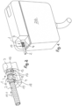
- a hose coupling 1 can be seen, which is provided at the hose end of a flexible hose line 2, which connects a water consumer or a water extraction point to a water supply.
- the hose coupling 1 has a coupling element 3 which is provided on the hose end of the flexible hose line 2 .
- the coupling element 3 can be releasably connected to a coupling counter-element 4 of the hose coupling 1 .
- At least one fluid channel 5, 6 is guided in the coupling element 3 and in the coupling counter-element 4, which fluid channels 5, 6 in the in the Figures 1, 2 and 7 to 9 shown holding position of the hose coupling 1 are liquid-tightly connected to each other.
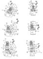
- the coupling element 3 has a coupling head 7, which is in the in the Figures 5 and 6 shown pivot position in a coupling head receptacle 8 on the coupling counter-element 4 can be used.
- the coupling element 3 and the coupling counter-element 4 are between the in Figure 5 and 6 pivot position shown and one in the Figures 7 to 9 shown holding position can be pivoted, in which holding position the coupling head 7 is held in the coupling head receptacle 8 and can be secured.
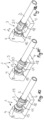
- the coupling element 3 is sleeve-shaped, with the of Flexible hose line 2 facing sleeve portion of the coupling element 3 is designed as a connecting piece 9, on which connecting piece 9 the associated hose end of the hose line 2 can be pushed.
- the coupling element 3 has a holding profile 10 on the outer circumference of the sleeve of its connecting piece 9 .
- the hose end of the hose line 2 can be attached to the connecting piece 9 by means of a enclosing hose end , pressed pinch or crimp sleeve 11 be secured.
- the coupling element 3 has an annular shoulder or annular flange 12 on the outer circumference, which serves as a sliding stop when the associated hose end of the hose line 2 is pushed on.
- the coupling element 3 has a ball head 13 on its sleeve end area facing away from the connecting piece 9, which is inserted into the as spherical socket designed coupling head recording 8 can be used.
- the coupling head 7 or the coupling head receptacle 8 can carry at least one circumferential seal which rests sealingly on the respective other element 8, 7 of the hose coupling 1.
- the coupling head 7 carries in a cross-sectional plane oriented transversely to the longitudinal axis of the coupling, preferably in the region of the equator of the Spherical shape of the ball head 13, a circumferential seal 14, which rests in the holding position on a wall of the coupling counter-element 4 that delimits the coupling head receptacle.
- a retaining flange 15 protrudes on the outer circumference, which in the retaining position at least partially engages behind a retaining wall 16, which retaining wall 16 is arranged in front of the coupling head receptacle 8 in the insertion direction Pf1 .
- a retaining groove 17 is provided in the insertion direction Pf1 in front of the coupling head receptacle 8 , while the groove wall facing away from the coupling head receptacle 8 is designed as a retaining wall 16 .
- the retaining groove 17 has a trapezoidal or conical cross-section, the greatest clear width of which is provided in the region of the groove opening.
- At least one retaining eyelet 18 for a securing means is provided on the coupling counter-piece 4, with the aid of which the coupling element 3 can be held and secured on the coupling counter-element against swinging out of the holding position.
- the securing means can be threaded through the retaining eyelet in such a way that the securing means wrapped around the hose line 2 or the coupling element 3 passes through the retaining eyelet.
- a retaining clip 19 is provided on the coupling counter-element 4, which has a clip-in opening open at the top.
- FIG 10 shown embodiment of the hose coupling 1 also has a retaining clip 19, which is opposite to that in the Figures 1 and 2 shown embodiment, however, is simplified.
- a downwardly open retaining clip 20 is used as a securing means.
- the securing means is formed by a retaining clip 21 open at the side.
- a cable tie 22 is used as a securing means, which cable tie 22 passes through the retaining eyelet 18 and wraps around the hose line 2.
- the securing means is formed by an adhesive tape or tape 23 which can be releasably closed at least at its tape ends.
- the exemplary embodiment shown is the securing means in the form of a U-shaped bracket 24 , the free bracket ends of the U bracket 24 protruding in the hose line 2 being able to be connected and secured to one another by means of a screw connection 25 .
- the coupling element 3 can also be held magnetically on the counter-coupling element 4 .
- a Be attached magnet instead of the eyelet 18 a Be attached magnet, which interacts with a ferrule made of ferromagnetic material or with a ferromagnetic counterpart, which is attached to the hose line. Since these magnetically effective variants represent a relatively loose fixation compared to the attachment options presented above, this only makes sense for an application in which the hose coupling has to be removed regularly and at short intervals.
- the hose coupling 1 shown here can be used to advantage wherever fluids are to be guided, at least in sections, via a flexible hose line.
- the hose coupling 1 shown here can preferably be used in a sanitary water line.
- the hose coupling 1 can be arranged, for example, at the water inlet or water inlet of a toilet cistern 26 .
- the coupling counter-element is held immovably on the toilet cistern 26 , while the coupling element 2 of the hose coupling 1 is provided on the associated hose end of the flexible hose line 2 .
Description
- Die Erfindung betrifft eine Schlauchkupplung mit einem Kupplungselement, das an einem Schlauchende einer flexiblen Schlauchleitung vorgesehen ist, und mit einem Kupplungs-Gegenelement, das mit dem Kupplungselement lösbar verbindbar ist, wobei im Kupplungselement und im Kupplungs-Gegenelement jeweils zumindest ein Fluidkanal geführt ist, und wobei die Fluidkanäle des Kupplungselements sowie des damit verbundenen Kupplungs-Gegenelements in einer Halteposition von Kupplungselement und Kupplungs-Gegenelement flüssigkeitsdicht miteinander verbunden sind.
- Sanitäre Auslaufarmaturen, Toiletten-Spülkästen, Wasch- oder Geschirrspülmaschinen und andere Wasserverbrauchsstellen werden zunehmend über flexible Schlauchleitungen an das Wasserversorgungsnetz angeschlossen. Dabei sind die Schlauchleitungen beispielsweise mit der sanitären Auslaufarmatur und/oder dem zulaufseitigen Wasseranschluss über eine Schlauchkupplung der eingangs erwähnten Art verbunden. Die vorbekannten Schlauchkupplungen weisen dazu ein Kupplungselement auf, das mit einem Kupplungs-Gegenelement über eine Schraubverbindung lösbar verbindbar ist. Dabei besteht das Problem, dass das am Schlauchende der flexiblen Schlauchleitung vorgesehene Kupplungselement unter beengten Platzverhältnissen nur mit erheblichem Aufwand mit dem Kupplungs-Gegenelement verschraubt werden kann, zumal die flexible Schlauchleitung und das mit ihr drehfest verbundene Kupplungselement sich Drehbewegungen um die Schlauch-Längsachse zu widersetzen scheint.
- Aus
US 2016/0003396 A1 ist ein Flüssigkeitsanschluss mit einem Muffenteil, einem kugelförmigen Ventil, das in den Muffenteil eingesetzt ist, und einem Steckerteil, das so konfiguriert ist, dass es an seinem Spitzenabschnitt in das kugelförmige Ventil eingesetzt werden kann, bekannt. - Aus
EP 3 112 737 A1 ist eine Kupplungsanordnung mit Kuppelkörpern und Kupplungsklammer für Rohre bekannt, wobei einer der Kupplungskörper mit einem Körperteil in ein Körperteil des anderen Kupplungskörpers mit seinem vorderen Ende durch ein vorderes Ende des aufnehmenden Kupplungskörpers einsetzbar ist. - Aus
CH 386 940 - Es besteht daher die Aufgabe, eine Schlauchkupplung der eingangs erwähnten Art zu schaffen, die sich durch eine einfache, schnelle und sichere Verbindung des Kupplungselements und des Kupplungs-Gegenelements auszeichnet.
- Die erfindungsgemäße Lösung dieser Aufgabe besteht bei der Schlauchkupplung der eingangs erwähnten Art insbesondere darin, dass das Kupplungselement oder das Kupplungs-Gegenelement einen Kupplungskopf aufweist, der in einer Schwenkposition in eine Kupplungskopf-Aufnahme des jeweils anderen Elements der Schlauchkupplung einsetzbar ist, und dass das Kupplungselement und das Kupplungs-Gegenelement zwischen der Schwenkposition und der Halteposition relativ zueinander verschwenkbar sind, in welche Halteposition der Kupplungskopf in der Kupplungskopf-Aufnahme gehalten ist.
- Die erfindungsgemäße Schlauchkupplung weist ein Kupplungselement auf, das an einem Schlauchende einer flexiblen Schlauchleitung vorgesehen ist. Mit diesem Kupplungselement ist ein Kupplungs-Gegenelement der Schlauchkupplung lösbar verbindbar. Im Kupplungselement und im Kupplungs-Gegenelement ist jeweils zumindest ein Fluidkanal geführt, wobei die im Kupplungselement beziehungsweise im Kupplungs-Gegenelement befindlichen Fluidkanäle in einer Halteposition von Kupplungselement und Kupplungs-Gegenelement flüssigkeitsdicht miteinander verbunden sind. Dabei weist das Kupplungselement oder das Kupplungs-Gegenelement der erfindungsgemäßen Schlauchkupplung einen Kupplungskopf auf, der in einer Schwenkposition in eine Kupplungskopf-Aufnahme des jeweils anderen Elements der Schlauchkupplung einsetzbar ist. Um das Kupplungselement und das Kupplungs-Gegenelement miteinander flüssigkeitsdicht zu verbinden, sind das Kupplungselement und das Kupplungs-Gegenelement zwischen der Schwenkposition und der Halteposition relativ zueinander verschwenkbar, in welcher Halteposition der Kupplungskopf in der Kupplungskopf-Aufnahme gehalten ist. Da bei der erfindungsgemäßen Schlauchkupplung das Kupplungselement mit dem Kupplungs-Gegenelement lediglich durch eine Schwenkbewegung in die Halteposition miteinander verbunden werden kann, und da zum Verbinden von Kupplungselement und Kupplungs-Gegenelement eine Schraubverbindung nicht benötigt wird, zeichnet sich die erfindungsgemäße Schlauchkupplung durch die einfache, schnelle und sichere Verbindung seines Kupplungselements und seines Kupplungs-Gegenelements aus.
- Um die Schwenkbewegung des Kupplungskopfes in der Kupplungskopf-Aufnahme zu vereinfachen und um das Kupplungselement um das Kupplungs-Gegenelement in der Halteposition dicht miteinander zu verbinden, ist der Kupplungskopf als Kugelkopf ausgebildet und die Kupplungskopf-Aufnahme als vorzugsweise kugelige Gelenkpfanne ausgestaltet.
- Die flüssigkeitsdichte Verbindung der erfindungsgemäßen Schlauchkupplung im Bereich ihres Kupplungselements, beziehungsweise des Kupplungs-Gegenelements, wird noch zusätzlich begünstigt, wenn der Kupplungskopf oder die Kupplungskopf-Aufnahme zumindest eine umlaufende Dichtung trägt, die an dem jeweils anderen Element der Schlauchkupplung dichtend anliegt.
- So kann beispielsweise in der Kupplungskopf-Aufnahme eine umlaufende Nut vorgesehen sein, in der ein Dichtring einliegt, welcher Dichtring am Kupplungskopf der Schlauchkupplung dichtend anliegt.
- Eine besonders vorteilhafte Ausführungsform, bei der in allen Schwenkpositionen von Kupplungselement und Kupplungs-Gegenelement eine hohe Dichtigkeit gewährleistet ist, sieht vor, dass der Kupplungskopf in einer quer zur Kupplungskopf-Längsachse orientierten Querschnittsebene, vorzugsweise im Bereich des Äquators der Kugelform des Kugelkopfes, eine umlaufende Dichtung trägt, welche Dichtung in der Halteposition an einer die Kupplungskopf-Aufnahme begrenzenden Wandung dicht anliegt.
- Eine konstruktiv einfache und besonders vorteilhafte Ausführungsform gemäß der Erfindung sieht vor, dass das Kupplungselement hülsenförmig ausgebildet ist, und dass der der flexiblen Schlauchleitung zugewandte Teilbereich des Kupplungselements als Anschlussstutzen ausgebildet ist, auf welchen Anschlussstutzen das zugeordnete Schlauchende der Schlauchleitung aufschiebbar ist. Um das den Anschlussstutzen umgreifende Schlauchende gegen ein axiales Abziehen vom Kupplungselement zu sichern, kann es vorteilhaft sein, wenn der Anschlussstutzen an seinem Stutzen-Außenumfang eine Halteprofilierung trägt. Damit sich das elastische Material der flexiblen Schlauchleitung im Bereich des Schlauchendes in die Halteprofilierung eingraben kann, ist es vorteilhaft, wenn das auf den Anschlussstutzen aufgeschobene Schlauchende von einer verpressten Crimp- oder Quetschhülse umschlossen ist. Mittels dieser verpressten Crimp- oder Quetschhülse wird das Schlauchende der flexiblen Schlauchleitung fest und sicher auf dem Anschlussstutzen des Kupplungselements gehalten.
- Um den Schiebeweg beim Aufschieben der flexiblen Schlauchleitung auf den Anschlussstutzen zu begrenzen, ist es vorteilhaft, wenn das Kupplungselement außenumfangsseitig einen Ringflansch oder Ringabsatz aufweist, der als Schiebeanschlag beim Aufschieben des zugeordneten Schlauchendes der Schlauchleitung dient.
- Eine besonders einfache und zweckmäßige Ausführungsform gemäß der Erfindung sieht vor, dass das Kupplungselement an seinem dem Anschlussstutzen abgewandten Hülsenendbereich den Kugelkopf trägt.
- Damit das Kupplungselement in der Halteposition sicher und fest im Kupplungs-Gegenelement gehalten ist, sieht eine bevorzugte Weiterbildung gemäß der Erfindung vor, dass in dem über das Schlauchende der Schlauchleitung vorstehenden Hülsen-Teilbereich des Kupplungselementes außenumfangsseitig ein Halteflansch vorsteht, der in der Halteposition zumindest bereichsweise eine Haltewandung hintergreift, welche Haltewandung in Einschieberichtung vor der Kupplungs-Aufnahme angeordnet ist. Da bei dieser weiterbildenden Ausführungsform das in das Kupplungs-Gegenelement eingeschobene Kupplungselement mit seinem außenumfangsseitig vorstehenden Halteflansch die Haltewandung hintergreift, wird das Kupplungselement gegen ein unbeabsichtigtes axiales Herausziehen aus dem Kupplungs-Gegenelement gesichert.
- Um die das Kupplungselement in der Halteposition sichernde Haltewandung auf einfache Weise auszubilden, ist es vorteilhaft, wenn in Einschieberichtung vor der Kupplungs-Aufnahme eine Haltenut vorgesehen ist, deren der Kupplungskopf-Aufnahme abgewandte Nutwand als Haltewandung ausgebildet ist.
- Der Halteflansch lässt sich auf einfache Weise derart in die Haltenut einschränken, bis der Halteflansch die als Haltewandung ausgebildete Nutwand hintergreift, wenn die Haltenut einen trapez- oder kegelförmigen Querschnitt aufweist, dessen größte lichte Weite im Bereich der Nutöffnung vorgesehen ist.
- Das Kupplungselement lässt sich in der Halteposition auf einfache Weise am Kupplungs-Gegenelement befestigen und gegen ein unbeabsichtigtes Verschwenken aus der Halteposition sichern, wenn der Schlauchkupplung wenigstens ein Sicherungsmittel zugeordnet ist, mit dessen Hilfe das Kupplungselement am Kupplungs-Gegenelement gegen ein Ausschwenken aus der Halteposition gehalten und gesichert ist.
- Dabei kann das Sicherungsmittel als Kabelbinder, als Tape, als Klettband, als U-Bügel oder als Halteklammer ausgebildet sein.
- Eine besonders einfache und vorteilhafte Ausführungsform gemäß der Erfindung sieht vor, dass am Kupplungs-Gegenstück zumindest eine Halteöse für das Sicherungsmittel vorgesehen ist, und dass das die Schlauchleitung oder das Kupplungselement umschlingende Sicherungsmittel die Halteöse durchsetzt.
- Die erfindungsgemäße Schlauchleitung lässt sich überall vorteilhaft einsetzen, wo Fluide zumindest abschnittsweise in einer flexiblen Schlauchleitung geführt werden. Eine bevorzugte Ausführungsform gemäß der Erfindung sieht jedoch vor, dass die Schlauchkupplung in eine sanitäre Wasserleitung einsetzbar ist. Dabei kann es vorteilhaft sein, wenn die Schlauchkupplung am Wassereingang oder am Wasserzulauf eines Toiletten-Spülkastens anordenbar ist.
- Weiterbildungen gemäß der Erfindung ergeben sich aus der nachstehenden Figurenbeschreibung in Verbindung mit den Ansprüchen sowie der Zeichnung. Nachstehend wird die Erfindung anhand bevorzugter Ausführungsbeispiele noch näher beschrieben.
- Es zeigt:
- Fig. 1
- einen Toiletten-Spülkasten, dessen Wasserzulauf über eine flexible Schlauchleitung an das Wasserversorgungsnetz angeschlossen ist, wobei der Toiletten-Spülkasten und die Schlauchleitung über eine Schlauchkupplung miteinander verbunden sind, die ein Kupplungselement und ein damit lösbar verbindbares Kupplungs-Gegenelement hat und wobei das Kupplungselement und das Kupplungs-Gegenelement relativ zueinander zwischen einer Schwenkposition und einer Halteposition verschwenkbar sind, in welcher hier gezeigten Halteposition das Kupplungselement und das Kupplungs-Gegenelement aneinander gehalten sind,
- Fig. 2
- das am Toiletten-Spülkasten gemäß
Figur 1 unverrückbar gehaltene Kupplungs-Gegenelement und das damit lösbar verbundene Kupplungselement in der Halteposition, - Fig. 3
- das hülsenförmige Kupplungselement der in den
Figuren 1 und 2 gezeigten Schlauchkupplung vor dem Einsetzen in das Kupplungs-Gegenelement, wobei der dem Kupplungs-Gegenelement zugewandte Hülsenendbereich des Kupplungselements als kugelförmiger Kupplungskopf ausgebildet und der abgewandte Hülsenendbereich als Anschlussstutzen ausgestaltet ist, auf den die Schlauchleitung aufgeschoben werden kann, - Fig. 4
- die Schlauchkupplung aus den
Figuren 1 bis 3 in einer Draufsicht in der bereits inFigur 3 gezeigten Position, - Fig. 5
- die Schlauchkupplung aus den
Figuren 1 bis 4 in einer Perspektivdarstellung, wobei das Kupplungselement mit seinem Kupplungskopf in einer Schwenkposition gezeigt ist, in welcher der Kupplungskopf in eine Kupplungskopf-Aufnahme am Kupplungs-Gegenelement schwenkbar einsetzbar ist, - Fig. 6
- die Schlauchkupplung aus den
Figuren 1 bis 5 in der bereits inFigur 5 gezeigten Schwenkposition in einer Draufsicht, - Fig. 7
- die Schlauchkupplung aus den
Figuren 1 bis 6 in einer perspektivischen Darstellung auf die Halteposition von Kupplungselement und Kupplungs-Gegenelement, - Fig. 8
- die in den
Figuren 1 bis 7 gezeigte Schlauchkupplung in der bereits inFigur 7 dargestellte Halteposition in einer Draufsicht, - Fig. 9
- die in den
Figuren 1 bis 8 gezeigte Schlauchkupplung in der bereits in denFiguren 7 und 8 dargestellten Halteposition in einem Längsschnitt, - Fig. 10
- die Schlauchkupplung aus den
Figuren 1 bis 9 , wobei das Kupplungselement am Kupplungs-Gegenelement mit einem nach oben hin offenen, aber gegenüber denFiguren 1 bis 9 vereinfacht ausgebildeten Halteclip in seiner Halteposition lösbar gesichert ist, - Fig. 11
- die Schlauchkupplung aus den
Figuren 1 bis 9 , wobei das Kupplungselement am Kupplungs-Gegenelement mit einem nach unten offenen Halteclip lösbar gesichert ist, - Fig. 12
- die Schlauchkupplung aus den
Figuren 1 bis 9 , wobei das Kupplungselement am Kupplungs-Gegenelement mit einem seitlich offenen Halteclip lösbar gesichert ist, - Fig. 13
- die Schlauchkupplung aus den
Figuren 1 bis 9 , wobei das Kupplungselement am Kupplungs-Gegenelement mit einem Kabelbinder gesichert ist, - Fig. 14
- die Schlauchkupplung aus den
Figuren 1 bis 9 , wobei das Kupplungselement am Kupplungs-Gegenelement mit einem Tape oder Klebeband gesichert ist und - Fig. 15
- die Schlauchkupplung aus den
Figuren 1 bis 9 , wobei das Kupplungselement am Kupplungs-Gegenelement mit einem U-förmigen Haltebügel gesichert ist, bei dem die beidseits der Schlauchleitung angeordneten freien Stege der U-Form mittels einer Schraubverbindung zusätzlich gesichert werden können. - In
Figur 1 ist eine Schlauchkupplung 1 erkennbar, die am Schlauchende einer flexiblen Schlauchleitung 2 vorgesehen ist, welche einen Wasserverbraucher oder eine Wasserentnahmestelle mit einer Wasserzufuhr verbindet. Die Schlauchkupplung 1 weist dazu ein Kupplungselement 3 auf, das an dem Schlauchende der flexiblen Schlauchleitung 2 vorgesehen ist. Das Kupplungselement 3 ist mit einem Kupplungs-Gegenelement 4 der Schlauchkupplung 1 lösbar verbindbar. Dabei ist im Kupplungselement 3 sowie im Kupplungs-Gegenelement 4 jeweils zumindest ein Fluidkanal 5, 6 geführt, welche Fluidkanäle 5, 6 in der in denFiguren 1, 2 und7 bis 9 gezeigten Halteposition der Schlauchkupplung 1 flüssigkeitsdicht miteinander verbunden sind. - In dem in den
Figuren 1 bis 9 gezeigten Ausführungsbeispiel weist das Kupplungselement 3 einen Kupplungskopf 7 auf, der in der in denFiguren 5 und 6 gezeigten Schwenkposition in eine Kupplungskopf-Aufnahme 8 am Kupplungs-Gegenelement 4 einsetzbar ist. Dabei sind das Kupplungselement 3 und das Kupplungs-Gegenelement 4 zwischen der inFigur 5 und 6 gezeigten Schwenkposition und einer in denFiguren 7 bis 9 dargestellten Halteposition verschwenkbar, in welcher Halteposition der Kupplungskopf 7 in der Kupplungskopf-Aufnahme 8 gehalten ist und gesichert werden kann. - Aus dem Längsschnitt in
Figur 9 wird deutlich, dass das Kupplungselement 3 hülsenförmig ausgebildet ist, wobei der der flexiblen Schlauchleitung 2 zugewandte Hülsen-Teilbereich des Kupplungselements 3 als Anschlussstutzen 9 ausgebildet ist, auf welchen Anschlussstutzen 9 das zugeordnete Schlauchende der Schlauchleitung 2 aufschiebbar ist. Um das auf den Anschlussstutzen 9 aufgeschobene Schlauchende auf dem Kupplungselement 3 zu halten, weist das Kupplungselement 3 am Hülsen-Außenumfang seines Anschlussstutzens 9 eine Halteprofilierung 10 auf. Damit sich das am Schlauchinnenumfang elastische Schlauchmaterial der flexiblen Schlauchleitung 2 fest in die Halteprofilierung 10 eingräbt, und damit das den Anschlussstutzen 9 umgreifende Schlauchende nicht unbeabsichtigt vom Anschlussstutzen 9 abgezogen werden kann, kann das Schlauchende der Schlauchleitung 2 auf dem Anschlussstutzen 9 mittels einer das Schlauchende umschließenden, verpressten Quetsch- oder Crimphülse 11 gesichert sein. - Das Kupplungselement 3 weist außenumfangsseitig einen Ringabsatz oder Ringflansch 12 auf, der als Schiebeanschlag beim Aufschieben des zugeordneten Schlauchendes der Schlauchleitung 2 dient. Um den in die Kupplungskopf-Aufnahme 8 eingesetzten Kupplungskopf 7 zwischen der Halteposition und der Schwenkposition verschwenken zu können und um diesen Bereich der Wasserführung abzudichten, weist das Kupplungselement 3 an seinem dem Anschlussstutzen 9 abgewandten Hülsen-Endbereich einen Kugelkopf 13 auf, der in die als kugelige Gelenkpfanne ausgestaltete Kupplungskopf-Aufnahme 8 einsetzbar ist. Um diesen Bereich der Schlauchkupplung noch zusätzlich abzudichten, kann der Kupplungskopf 7 oder die Kupplungskopf-Aufnahme 8 zumindest eine umlaufende Dichtung tragen, die an dem jeweils anderen Element 8, 7 der Schlauchkupplung 1 dichtend anliegt. In dem hier dargestellten Ausführungsbeispiel trägt der Kupplungskopf 7 in einer quer zur Kupplungs-Längsachse orientierten Querschnittsebene, vorzugsweise im Bereich des Äquators der Kugelform des Kugelkopfes 13, eine umlaufende Dichtung 14, die in der Halteposition an einer die Kupplungskopf-Aufnahme begrenzenden Wandung des Kupplungs-Gegenelements 4 anliegt.
- Wie insbesondere aus den
Figuren 3 bis 9 deutlich wird, steht in dem über das Schlauchende der Schlauchleitung 2 vorstehenden Hülsen-Teilbereich des Kupplungselementes 3 außenumfangsseitig ein Halteflansch 15 vor, der in der Halteposition zumindest bereichsweise eine Haltewandung 16 hintergreift, welche Haltewandung 16 in Einschieberichtung Pf1 vor der Kupplungskopf-Aufnahme 8 angeordnet ist. Um diese Haltewandung 16 auf einfache Weise auszubilden, ist in Einschieberichtung Pf1 vor der Kupplungskopf-Aufnahme 8 eine Haltenut 17 vorgesehen, während die Kupplungskopf-Aufnahme 8 abgewandte Nutwand als Haltewandung 16 ausgebildet ist. Damit der Halteflansch 15 beim Einschwenken des Kupplungselements 3 in die Halteposition leicht in die Haltenut 17 findet, weist die Haltenut 17 einen trapez- oder kegelförmigen Querschnitt auf, dessen größte lichte Weite im Bereich der Nutöffnung vorgesehen ist. - Am Kupplungs-Gegenstück 4 ist zumindest eine Halteöse 18 für ein Sicherungsmittel vorgesehen, mit dessen Hilfe das Kupplungselement 3 am Kupplungs-Gegenelement gegen ein Ausschwenken aus der Halteposition gehalten und gesichert werden kann. Dabei kann das Sicherungsmittel derart durch die Halteöse gefädelt werden, dass das die Schlauchleitung 2 oder das Kupplungselement 3 umschlingende Sicherungsmittel die Halteöse durchsetzt.
- Aus einem Vergleich der
Figuren 1 bis 15 wird deutlich, dass die verschiedensten Sicherungsmittel verwendbar sind. In dem in denFiguren 1 bis 9 gezeigten Ausführungsbeispiel ist am Kupplungs-Gegenelement 4 ein Halteclip 19 vorgesehen, der eine nach oben hin offene Einclipsöffnung hat. Durch Einschwenken des Kupplungselements 3 in die Halteposition werden die freien Enden des Halteclip 19 im Bereich der Einclipsöffnung derart geweitet, bis das Kupplungselement 3 in den Halteclip 19 einrastet und die freien Ende des Halteclip wieder zurückfedern können. - Das in
Figur 10 gezeigte Ausführungsbeispiel der Schlauchkupplung 1 weist ebenfalls einen Halteclip 19 auf, der gegenüber den in denFiguren 1 und 2 gezeigten Ausführungsbeispiel jedoch vereinfacht ausgebildet ist. - Bei dem in
Figur 11 gezeigten Ausführungsbeispiel ist ein nach unten geöffneter Halteclip 20 als Sicherungsmittel verwendet. - Bei dem in
Figur 12 gezeigten Ausführungsbeispiel wird das Sicherungsmittel durch einen seitlich offenen Halteclip 21 gebildet. - Bei dem in
Figur 13 gezeigten Ausführungsbeispiel der Schlauchkupplung 1 wird ein Kabelbinder 22 als Sicherungsmittel verwendet, welcher Kabelbinder 22 die Halteöse 18 durchsetzt und die Schlauchleitung 2 umschlingt. - In
Figur 14 ist das Sicherungsmittel durch ein Klebeband oder Tape 23 gebildet, das zumindest an seinen Bandenden lösbar verschließbar ist. - Bei dem in
Figur 15 gezeigten Ausführungsbeispiel ist das Sicherungsmittel als U-förmiger Bügel 24 ausgebildet, wobei die bei der Schlauchleitung 2 überstehenden freien Bügelenden des U-Bügels 24 mittels einer Schraubverbindung 25 miteinander verbindbar und sicherbar sind. Über die oben beschriebenen Befestigungsmöglichkeiten hinaus kann das Kupplungselement 3 aber auch magnetisch am Kupplung-Gegenelement 4 gehalten werden. So könnte beispielsweise anstelle der Öse 18 ein Magnet angebracht sein, der mit einer Quetschhülse aus ferromagnetischem Material oder mit einem ferromagnetischen Gegenstück zusammenwirkt, welches an der Schlauchleitung angebracht ist. Da diese magnetisch wirksamen Varianten im Vergleich zu den oben dargestellten Befestigungsmöglichkeiten eine relativ lose Fixierung darstellen, ist dies nur für eine Anwendung sinnvoll, bei der die Schlauchkupplung regelmäßig und in kurzen Zeitabständen entfernt werden muss. - Die hier dargestellte Schlauchkupplung 1 lässt sich überall vorteilhaft einsetzen, wo Fluide zumindest abschnittsweise über eine flexible Schlauchleitung geführt werden sollen. Die hier dargestellte Schlauchkupplung 1 ist jedoch bevorzugt in eine sanitäre Wasserleitung einsetzbar. Hier kann die Schlauchkupplung 1 beispielsweise am Wassereingang oder Wasserzulauf eines Toiletten-Spülkastens 26 angeordnet werden. Dabei ist das Kupplungs-Gegenelement am Toiletten-Spülkasten 26 unverrückbar gehalten, während demgegenüber das Kupplungselement 2 der Schlauchkupplung 1 am zugeordneten Schlauchende der flexiblen Schlauchleitung 2 vorgesehen ist.
-
- 1
- Schlauchkupplung
- 2
- Schlauchleitung
- 3
- Kupplungselement
- 4
- Kupplungs-Gegenelement
- 5
- Fluidkanal
- 6
- Fluidkanal
- 7
- Kupplungskopf
- 8
- Kupplungskopf-Aufnahme
- 9
- Anschlussstutzen
- 10
- Halteprofilierung
- 11
- Quetschhülse
- 12
- Ringflansch
- 13
- Kugelkopf
- 14
- Dichtung
- 15
- Halteflansch
- 16
- Haltewandung
- 17
- Haltenut
- 18
- Halteöse
- 19
- Halteclip (gemäß den
Figuren 1, 2 und10 ) - 20
- Halteclip
- 21
- Halteclip
- 22
- Kabelbinder
- 23
- Klebeband oder Tape
- 24
- U-Bügel
- 25
- Schraubverbindung
- 26
- Toiletten-Spülkasten
- Pf1
- Einschieberichtung
Claims (15)
- Schlauchkupplung (1) mit einem Kupplungselement (3), das ausgelegt ist, ein Schlauchende einer flexiblen Schlauchleitung (2) halten zu können, und mit einem Kupplungs-Gegenelement (4), das mit dem Kupplungselement (3) lösbar verbindbar ist, wobei im Kupplungselement (3) und im Kupplungs-Gegenelement (4) jeweils zumindest ein Fluidkanal (5, 6) geführt ist, und wobei die Fluidkanäle (5, 6) des Kupplungselements (3) sowie des damit verbundenen Kupplungs-Gegenelements (4) in einer Halteposition von Kupplungselement (3) und Kupplungs-Gegenelement (4) flüssigkeitsdicht miteinander verbunden sind, wobei das Kupplungselement (3) oder das Kupplungs-Gegenelement (4) einen Kupplungskopf (7) aufweist, der in einer Schwenkposition in eine Kupplungskopf-Aufnahme des jeweils anderen Elements (4; 3) der Schlauchkupplung (1) einsetzbar ist, und das Kupplungselement (3) und das Kupplungs-Gegenelement (4) zwischen der Schwenkposition und der Halteposition relativ zueinander verschwenkbar sind, in welcher Halteposition der Kupplungskopf (7) in der Kupplungskopf-Aufnahme (8) gehalten ist,
dadurch gekennzeichnet, dass der Kupplungskopf (7) als Kugelkopf (13) ausgebildet und die Kupplungskopf-Aufnahme (8) als Gelenkpfanne ausgestaltet ist. - Schlauchkupplung nach Anspruch 1, dadurch gekennzeichnet, dass die Kupplungskopf-Aufnahme (8) als kugelige Gelenkpfanne ausgestaltet ist.
- Schlauchkupplung nach Anspruch 1 oder 2, dadurch gekennzeichnet, dass der Kupplungskopf (7) oder die Kupplungskopf-Aufnahme (8) zumindest eine umlaufende Dichtung trägt, die an dem jeweils anderen Element (8, 7) der Schlauchkupplung (1) dichtend anliegt.
- Schlauchkupplung nach einem der Ansprüche 1 bis 3, dadurch gekennzeichnet, dass der Kupplungskopf (7) in einer quer zur Kupplungskopf-Längsachse orientierten Querschnittsebene, vorzugsweise im Bereich des Äquators der Kugelform des Kugelkopfes (13), eine umlaufende Dichtung (14) trägt, welche Dichtung (14) in der Halteposition an einer die Kupplungskopf-Aufnahme (8) begrenzenden Wandung dicht anliegt.
- Schlauchkupplung nach einem der Ansprüche 1 bis 4, dadurch gekennzeichnet, dass das Kupplungselement (3) hülsenförmig ausgebildet ist, und dass der der flexiblen Schlauchleitung (2) zugewandte Teilbereich des Kupplungselements (3) als Anschlussstutzen (9) ausgebildet ist, auf welchen Anschlussstutzen (9) das zugeordnete Schlauchende der Schlauchleitung (2) aufschiebbar ist.
- Schlauchkupplung nach Anspruch 5, dadurch gekennzeichnet, dass das Kupplungselement (3) außenumfangsseitig einen Ringflansch (12) oder Ringabsatz aufweist, der als Schiebeanschlag beim Aufschieben des zugeordneten Schlauchendes der Schlauchleitung (2) dient.
- Schlauchkupplung nach Anspruch 5 oder 6, dadurch gekennzeichnet, dass das Kupplungselement (3) an seinem dem Anschlussstutzen (9) abgewandten Hülsenendbereich den Kugelkopf (13) trägt.
- Schlauchkupplung nach einem der Ansprüche 5 bis 7, dadurch gekennzeichnet, dass in dem über das Schlauchende der Schlauchleitung (2) vorstehenden Hülsen-Teilbereich des Kupplungselementes (3) außenumfangsseitig ein Halteflansch (15) vorsteht, der in der Halteposition zumindest bereichsweise eine Haltewandung (16) hintergreift, welche Haltewandung (16) in Einschieberichtung (Pf1) vor der Kupplungskopf-Aufnahme (9) angeordnet ist.
- Schlauchkupplung nach Anspruch 8, dadurch gekennzeichnet, dass in Einschieberichtung (Pf1) vor der Kupplungskopf-Aufnahme (8) eine Haltenut (17) vorgesehen ist, deren die Kupplungskopf-Aufnahme (8) abgewandte Nutwand als Haltewandung (16) ausgebildet ist.
- Schlauchkupplung nach Anspruch 9, dadurch gekennzeichnet, dass die Haltenut (17) einen trapez- oder kegelförmigen Querschnitt aufweist, dessen größte lichte Weite im Bereich der Nutöffnung vorgesehen ist.
- Schlauchkupplung nach einem der Ansprüche 1 bis 10,
dadurch gekennzeichnet, dass der Schlauchkupplung (1) wenigstens ein Sicherungsmittel zugeordnet ist, mit dessen Hilfe das Kupplungselement (3) am Kupplungs-Gegenelement (4) gegen ein Ausschwenken aus der Halteposition gehalten und gesichert ist. - Schlauchkupplung nach einem der Ansprüche 1 bis 11,
dadurch gekennzeichnet, dass das Sicherungsmittel als Kabelbinder (22), als Klebeband oder Tape (23), als Klettband, als U-Bügel (24), als Halteklammer oder Halteclip (19, 20, 21) ausgebildet ist. - Schlauchkupplung nach Anspruch 11 oder 12, dadurch gekennzeichnet, dass am Kupplungs-Gegenstück (4) zumindest eine Halteöse (18) für das Sicherungsmittel vorgesehen ist, und dass das die Schlauchleitung (2) oder das Kupplungselement (3) umschlingende Sicherungsmittel die Halteöse (18) durchsetzt.
- Schlauchkupplung nach einem der Ansprüche 1 bis 13, dadurch gekennzeichnet, dass die Schlauchkupplung (1) in eine sanitäre Wasserleitung einsetzbar ist.
- Schlauchkupplung nach einem der Ansprüche 1 bis 14, dadurch gekennzeichnet, dass die Schlauchkupplung (1) am Wassereingang oder Wasserzulauf eines Toiletten-Spülkastens (26) anordenbar ist.
Applications Claiming Priority (2)
| Application Number | Priority Date | Filing Date | Title |
|---|---|---|---|
| DE202020100810.2U DE202020100810U1 (de) | 2020-02-14 | 2020-02-14 | Schlauchkupplung |
| PCT/EP2020/087303 WO2021160328A1 (de) | 2020-02-14 | 2020-12-18 | Schlauchkupplung |
Publications (2)
| Publication Number | Publication Date |
|---|---|
| EP4034793A1 EP4034793A1 (de) | 2022-08-03 |
| EP4034793B1 true EP4034793B1 (de) | 2023-06-07 |
Family
ID=74175791
Family Applications (1)
| Application Number | Title | Priority Date | Filing Date |
|---|---|---|---|
| EP20838985.8A Active EP4034793B1 (de) | 2020-02-14 | 2020-12-18 | Schlauchkupplung |
Country Status (5)
| Country | Link |
|---|---|
| EP (1) | EP4034793B1 (de) |
| CN (1) | CN114981580A (de) |
| DE (1) | DE202020100810U1 (de) |
| ES (1) | ES2955361T3 (de) |
| WO (1) | WO2021160328A1 (de) |
Family Cites Families (9)
| Publication number | Priority date | Publication date | Assignee | Title |
|---|---|---|---|---|
| CH386940A (de) * | 1961-09-14 | 1965-01-15 | Gebert & Cie Armaturen & Appar | Ablaufvorrichtung an Unterputz-Spülkasten |
| JPH10292886A (ja) * | 1997-04-18 | 1998-11-04 | Fushiman Kk | ボールジョイント |
| AR078273A1 (es) * | 2009-09-11 | 2011-10-26 | Victaulic Co Of America | Conjunto flexible para rociadores |
| DE102010014686A1 (de) * | 2010-04-12 | 2011-10-13 | Röhrenwerk Kupferdreh Carl Hamm GmbH | Rohrkupplung für Hochdruckrohre |
| JP6706727B2 (ja) * | 2014-07-03 | 2020-06-10 | ダイセン株式会社 | 流体継手 |
| EP3112737B1 (de) * | 2015-07-03 | 2019-09-04 | MANN+HUMMEL GmbH | Kupplungsvorrichtung mit kupplungskörpern und kupplungshalterung für rohre |
| DE102015014816B4 (de) * | 2015-11-14 | 2018-01-18 | Audi Ag | Kupplungselement zum Verbinden fluidführender Leitungen sowie entsprechende Kupplungsanordnung |
| DE202018101119U1 (de) * | 2018-02-28 | 2019-05-31 | Neoperl Gmbh | Kugelgelenk |
| CN208429043U (zh) * | 2018-06-26 | 2019-01-25 | 郑州比克电池有限公司 | 一种电动汽车电池包模组线束固定支架 |
-
2020
- 2020-02-14 DE DE202020100810.2U patent/DE202020100810U1/de active Active
- 2020-12-18 WO PCT/EP2020/087303 patent/WO2021160328A1/de active Search and Examination
- 2020-12-18 CN CN202080091609.8A patent/CN114981580A/zh active Pending
- 2020-12-18 ES ES20838985T patent/ES2955361T3/es active Active
- 2020-12-18 EP EP20838985.8A patent/EP4034793B1/de active Active
Also Published As
| Publication number | Publication date |
|---|---|
| DE202020100810U1 (de) | 2021-05-17 |
| WO2021160328A1 (de) | 2021-08-19 |
| ES2955361T3 (es) | 2023-11-30 |
| EP4034793A1 (de) | 2022-08-03 |
| CN114981580A (zh) | 2022-08-30 |
Similar Documents
| Publication | Publication Date | Title |
|---|---|---|
| EP2964992B1 (de) | Steckverbindung für zwei rohre und verfahren zur montage der steckverbindung | |
| EP0787864B1 (de) | Sanitäre Sicherungseinrichtung | |
| EP2384382B9 (de) | Durchflussmengenregler | |
| EP0511538A2 (de) | Ventilvorrichtung für einen Katheter | |
| EP3169853B1 (de) | Flexible schlauchleitung | |
| EP1672265A1 (de) | Verbindungsanordnung für eine Fluidleitung, insbesondere Hahnstück | |
| EP2582889B1 (de) | Wasserauslauf-garnitur mit kugelgelenk | |
| DE202013002188U1 (de) | Sanitäres Einbauteil, Innenschlauchanordnung für eine Sanitärarmatur und Sanitärarmatur | |
| EP1264127B1 (de) | Drehbarer absperrhahn für eine steckkupplung mit abgewinkeltem anschlussstutzen | |
| DE202010009135U1 (de) | Dichtring, Durchflussmengenregler sowie Brausearmatur mit einem Durchflussmengenregler | |
| DE102013003926A1 (de) | Sanitäres Einbauteil, Innenschlauchanordnung für eine Sanitärarmatur und Sanitärarmatur | |
| DE202020104394U1 (de) | Sanitärschnittstelle, Sanitärarmatur, Baukasten zur Herstellung einer Sanitärschnittstelle und Verwendung einer Sanitärschnittstelle | |
| EP3759285B9 (de) | Kugelgelenk | |
| EP4034793B1 (de) | Schlauchkupplung | |
| EP2453157B1 (de) | Verbindungssystem zur Installation eines wasserführenden Gerätes | |
| EP3322923B1 (de) | Sanitärer leitungsanschluss | |
| DE4205142C1 (de) | ||
| DE102010023962A1 (de) | Dichtring, Durchflussmengenregler sowie Brausearmatur mit einem Durchflussmengenregler | |
| DE102020103960A1 (de) | Schlauchkupplung | |
| EP3205783B1 (de) | Sanitäres rückflussverhindererventil | |
| DE102014226395A1 (de) | Steckarmatur | |
| DE102012221675A1 (de) | Sanitärarmatur und Fluidleitung hierfür | |
| DE102014010521B4 (de) | Schlauchanschluss | |
| DE2426790A1 (de) | Schnellanschluss fuer wasserhaehne | |
| EP2975311B1 (de) | Schlauchverschraubung |
Legal Events
| Date | Code | Title | Description |
|---|---|---|---|
| STAA | Information on the status of an ep patent application or granted ep patent |
Free format text: STATUS: UNKNOWN |
|
| STAA | Information on the status of an ep patent application or granted ep patent |
Free format text: STATUS: THE INTERNATIONAL PUBLICATION HAS BEEN MADE |
|
| PUAI | Public reference made under article 153(3) epc to a published international application that has entered the european phase |
Free format text: ORIGINAL CODE: 0009012 |
|
| STAA | Information on the status of an ep patent application or granted ep patent |
Free format text: STATUS: REQUEST FOR EXAMINATION WAS MADE |
|
| 17P | Request for examination filed |
Effective date: 20220425 |
|
| AK | Designated contracting states |
Kind code of ref document: A1 Designated state(s): AL AT BE BG CH CY CZ DE DK EE ES FI FR GB GR HR HU IE IS IT LI LT LU LV MC MK MT NL NO PL PT RO RS SE SI SK SM TR |
|
| GRAP | Despatch of communication of intention to grant a patent |
Free format text: ORIGINAL CODE: EPIDOSNIGR1 |
|
| STAA | Information on the status of an ep patent application or granted ep patent |
Free format text: STATUS: GRANT OF PATENT IS INTENDED |
|
| INTG | Intention to grant announced |
Effective date: 20221025 |
|
| GRAS | Grant fee paid |
Free format text: ORIGINAL CODE: EPIDOSNIGR3 |
|
| DAV | Request for validation of the european patent (deleted) | ||
| DAX | Request for extension of the european patent (deleted) | ||
| GRAA | (expected) grant |
Free format text: ORIGINAL CODE: 0009210 |
|
| STAA | Information on the status of an ep patent application or granted ep patent |
Free format text: STATUS: THE PATENT HAS BEEN GRANTED |
|
| AK | Designated contracting states |
Kind code of ref document: B1 Designated state(s): AL AT BE BG CH CY CZ DE DK EE ES FI FR GB GR HR HU IE IS IT LI LT LU LV MC MK MT NL NO PL PT RO RS SE SI SK SM TR |
|
| REG | Reference to a national code |
Ref country code: GB Ref legal event code: FG4D Free format text: NOT ENGLISH |
|
| REG | Reference to a national code |
Ref country code: CH Ref legal event code: EP Ref country code: AT Ref legal event code: REF Ref document number: 1576023 Country of ref document: AT Kind code of ref document: T Effective date: 20230615 Ref country code: DE Ref legal event code: R096 Ref document number: 502020003747 Country of ref document: DE |
|
| REG | Reference to a national code |
Ref country code: LT Ref legal event code: MG9D |
|
| REG | Reference to a national code |
Ref country code: NL Ref legal event code: MP Effective date: 20230607 |
|
| PG25 | Lapsed in a contracting state [announced via postgrant information from national office to epo] |
Ref country code: SE Free format text: LAPSE BECAUSE OF FAILURE TO SUBMIT A TRANSLATION OF THE DESCRIPTION OR TO PAY THE FEE WITHIN THE PRESCRIBED TIME-LIMIT Effective date: 20230607 Ref country code: NO Free format text: LAPSE BECAUSE OF FAILURE TO SUBMIT A TRANSLATION OF THE DESCRIPTION OR TO PAY THE FEE WITHIN THE PRESCRIBED TIME-LIMIT Effective date: 20230907 |
|
| PG25 | Lapsed in a contracting state [announced via postgrant information from national office to epo] |
Ref country code: RS Free format text: LAPSE BECAUSE OF FAILURE TO SUBMIT A TRANSLATION OF THE DESCRIPTION OR TO PAY THE FEE WITHIN THE PRESCRIBED TIME-LIMIT Effective date: 20230607 Ref country code: NL Free format text: LAPSE BECAUSE OF FAILURE TO SUBMIT A TRANSLATION OF THE DESCRIPTION OR TO PAY THE FEE WITHIN THE PRESCRIBED TIME-LIMIT Effective date: 20230607 Ref country code: LV Free format text: LAPSE BECAUSE OF FAILURE TO SUBMIT A TRANSLATION OF THE DESCRIPTION OR TO PAY THE FEE WITHIN THE PRESCRIBED TIME-LIMIT Effective date: 20230607 Ref country code: LT Free format text: LAPSE BECAUSE OF FAILURE TO SUBMIT A TRANSLATION OF THE DESCRIPTION OR TO PAY THE FEE WITHIN THE PRESCRIBED TIME-LIMIT Effective date: 20230607 Ref country code: HR Free format text: LAPSE BECAUSE OF FAILURE TO SUBMIT A TRANSLATION OF THE DESCRIPTION OR TO PAY THE FEE WITHIN THE PRESCRIBED TIME-LIMIT Effective date: 20230607 Ref country code: GR Free format text: LAPSE BECAUSE OF FAILURE TO SUBMIT A TRANSLATION OF THE DESCRIPTION OR TO PAY THE FEE WITHIN THE PRESCRIBED TIME-LIMIT Effective date: 20230908 |
|
| REG | Reference to a national code |
Ref country code: ES Ref legal event code: FG2A Ref document number: 2955361 Country of ref document: ES Kind code of ref document: T3 Effective date: 20231130 |
|
| PG25 | Lapsed in a contracting state [announced via postgrant information from national office to epo] |
Ref country code: FI Free format text: LAPSE BECAUSE OF FAILURE TO SUBMIT A TRANSLATION OF THE DESCRIPTION OR TO PAY THE FEE WITHIN THE PRESCRIBED TIME-LIMIT Effective date: 20230607 |
|
| PG25 | Lapsed in a contracting state [announced via postgrant information from national office to epo] |
Ref country code: SK Free format text: LAPSE BECAUSE OF FAILURE TO SUBMIT A TRANSLATION OF THE DESCRIPTION OR TO PAY THE FEE WITHIN THE PRESCRIBED TIME-LIMIT Effective date: 20230607 |
|
| PG25 | Lapsed in a contracting state [announced via postgrant information from national office to epo] |
Ref country code: IS Free format text: LAPSE BECAUSE OF FAILURE TO SUBMIT A TRANSLATION OF THE DESCRIPTION OR TO PAY THE FEE WITHIN THE PRESCRIBED TIME-LIMIT Effective date: 20231007 |
|
| PG25 | Lapsed in a contracting state [announced via postgrant information from national office to epo] |
Ref country code: SM Free format text: LAPSE BECAUSE OF FAILURE TO SUBMIT A TRANSLATION OF THE DESCRIPTION OR TO PAY THE FEE WITHIN THE PRESCRIBED TIME-LIMIT Effective date: 20230607 Ref country code: SK Free format text: LAPSE BECAUSE OF FAILURE TO SUBMIT A TRANSLATION OF THE DESCRIPTION OR TO PAY THE FEE WITHIN THE PRESCRIBED TIME-LIMIT Effective date: 20230607 Ref country code: RO Free format text: LAPSE BECAUSE OF FAILURE TO SUBMIT A TRANSLATION OF THE DESCRIPTION OR TO PAY THE FEE WITHIN THE PRESCRIBED TIME-LIMIT Effective date: 20230607 Ref country code: PT Free format text: LAPSE BECAUSE OF FAILURE TO SUBMIT A TRANSLATION OF THE DESCRIPTION OR TO PAY THE FEE WITHIN THE PRESCRIBED TIME-LIMIT Effective date: 20231009 Ref country code: IS Free format text: LAPSE BECAUSE OF FAILURE TO SUBMIT A TRANSLATION OF THE DESCRIPTION OR TO PAY THE FEE WITHIN THE PRESCRIBED TIME-LIMIT Effective date: 20231007 Ref country code: EE Free format text: LAPSE BECAUSE OF FAILURE TO SUBMIT A TRANSLATION OF THE DESCRIPTION OR TO PAY THE FEE WITHIN THE PRESCRIBED TIME-LIMIT Effective date: 20230607 Ref country code: CZ Free format text: LAPSE BECAUSE OF FAILURE TO SUBMIT A TRANSLATION OF THE DESCRIPTION OR TO PAY THE FEE WITHIN THE PRESCRIBED TIME-LIMIT Effective date: 20230607 |
|
| PG25 | Lapsed in a contracting state [announced via postgrant information from national office to epo] |
Ref country code: PL Free format text: LAPSE BECAUSE OF FAILURE TO SUBMIT A TRANSLATION OF THE DESCRIPTION OR TO PAY THE FEE WITHIN THE PRESCRIBED TIME-LIMIT Effective date: 20230607 |
|
| REG | Reference to a national code |
Ref country code: DE Ref legal event code: R097 Ref document number: 502020003747 Country of ref document: DE |
|
| PLBE | No opposition filed within time limit |
Free format text: ORIGINAL CODE: 0009261 |
|
| STAA | Information on the status of an ep patent application or granted ep patent |
Free format text: STATUS: NO OPPOSITION FILED WITHIN TIME LIMIT |
|
| PG25 | Lapsed in a contracting state [announced via postgrant information from national office to epo] |
Ref country code: DK Free format text: LAPSE BECAUSE OF FAILURE TO SUBMIT A TRANSLATION OF THE DESCRIPTION OR TO PAY THE FEE WITHIN THE PRESCRIBED TIME-LIMIT Effective date: 20230607 |
|
| PGFP | Annual fee paid to national office [announced via postgrant information from national office to epo] |
Ref country code: DE Payment date: 20240205 Year of fee payment: 4 |
|
| PG25 | Lapsed in a contracting state [announced via postgrant information from national office to epo] |
Ref country code: SI Free format text: LAPSE BECAUSE OF FAILURE TO SUBMIT A TRANSLATION OF THE DESCRIPTION OR TO PAY THE FEE WITHIN THE PRESCRIBED TIME-LIMIT Effective date: 20230607 |