EP4033677B1 - Schwenkmechanismus für kommunikationseinheiten - Google Patents
Schwenkmechanismus für kommunikationseinheiten Download PDFInfo
- Publication number
- EP4033677B1 EP4033677B1 EP21209000.5A EP21209000A EP4033677B1 EP 4033677 B1 EP4033677 B1 EP 4033677B1 EP 21209000 A EP21209000 A EP 21209000A EP 4033677 B1 EP4033677 B1 EP 4033677B1
- Authority
- EP
- European Patent Office
- Prior art keywords
- unit
- elevation
- axis
- receiving unit
- azimuth
- Prior art date
- Legal status (The legal status is an assumption and is not a legal conclusion. Google has not performed a legal analysis and makes no representation as to the accuracy of the status listed.)
- Active
Links
Images


Classifications
-
- H—ELECTRICITY
- H01—ELECTRIC ELEMENTS
- H01Q—ANTENNAS, i.e. RADIO AERIALS
- H01Q3/00—Arrangements for changing or varying the orientation or the shape of the directional pattern of the waves radiated from an antenna or antenna system
- H01Q3/02—Arrangements for changing or varying the orientation or the shape of the directional pattern of the waves radiated from an antenna or antenna system using mechanical movement of antenna or antenna system as a whole
- H01Q3/08—Arrangements for changing or varying the orientation or the shape of the directional pattern of the waves radiated from an antenna or antenna system using mechanical movement of antenna or antenna system as a whole for varying two co-ordinates of the orientation
-
- G—PHYSICS
- G02—OPTICS
- G02B—OPTICAL ELEMENTS, SYSTEMS OR APPARATUS
- G02B23/00—Telescopes, e.g. binoculars; Periscopes; Instruments for viewing the inside of hollow bodies; Viewfinders; Optical aiming or sighting devices
- G02B23/16—Housings; Caps; Mountings; Supports, e.g. with counterweight
- G02B23/165—Equatorial mounts
-
- H—ELECTRICITY
- H04—ELECTRIC COMMUNICATION TECHNIQUE
- H04B—TRANSMISSION
- H04B10/00—Transmission systems employing electromagnetic waves other than radio-waves, e.g. infrared, visible or ultraviolet light, or employing corpuscular radiation, e.g. quantum communication
- H04B10/11—Arrangements specific to free-space transmission, i.e. transmission through air or vacuum
- H04B10/112—Line-of-sight transmission over an extended range
- H04B10/1123—Bidirectional transmission
-
- H—ELECTRICITY
- H04—ELECTRIC COMMUNICATION TECHNIQUE
- H04B—TRANSMISSION
- H04B10/00—Transmission systems employing electromagnetic waves other than radio-waves, e.g. infrared, visible or ultraviolet light, or employing corpuscular radiation, e.g. quantum communication
- H04B10/11—Arrangements specific to free-space transmission, i.e. transmission through air or vacuum
- H04B10/112—Line-of-sight transmission over an extended range
- H04B10/1123—Bidirectional transmission
- H04B10/1125—Bidirectional transmission using a single common optical path
-
- H—ELECTRICITY
- H04—ELECTRIC COMMUNICATION TECHNIQUE
- H04B—TRANSMISSION
- H04B10/00—Transmission systems employing electromagnetic waves other than radio-waves, e.g. infrared, visible or ultraviolet light, or employing corpuscular radiation, e.g. quantum communication
- H04B10/11—Arrangements specific to free-space transmission, i.e. transmission through air or vacuum
- H04B10/118—Arrangements specific to free-space transmission, i.e. transmission through air or vacuum specially adapted for satellite communication
Definitions
- the present description relates to a communication unit and its movement mechanism for a pivoting movement about an elevation axis and a rotational movement about an azimuth axis. Furthermore, the description relates to a communication satellite with such a communication unit.
- Satellite constellations have recently become increasingly popular.
- a satellite constellation can be described as a satellite network with a number of satellites, each of which orbits the earth in a predetermined orbit and covers a specific area of the earth's surface.
- the number of satellites in a satellite constellation and the course of the earth's orbits can be such that at least one satellite can establish a direct optical connection to any point on the earth's surface at any time.
- DE 10 2016 121 919 A1 describes a satellite constellation with a plurality of communications satellites as well as an approach to data transmission and routing between the individual communications satellites.
- DE 10 2017 127 813 A1 describes a system and a method for adjusting a radiation direction of an optical communication signal between a communication platform and a remote station.
- Kesner Jessica E. et al. "Compact optical gimbal as a conformal beam director for large field-of-regard lasercom applications", Proceedings of SPIE, IEEE, US, Vol. 9354, 93540K-1 to 93540K -10 describes a swivel device for an optical transmitting/receiving unit.
- the transmitting/receiving unit is arranged on a rotary table with a swivel drive (elevation drive).
- the elevation drive can be moved radially to different positions between the center of the rotary table and the outer edge of the rotary table.
- JP 2 806 659 B2 describes a transmitting/receiving unit for a satellite.
- the transmitting/receiving unit can be swiveled around several axes, and the axes are offset from each other.
- US 6 259 415 describes an antenna system with an antenna that is mounted on a turntable and can be swiveled around an azimuth axis and an elevation axis.
- JP H08 288 732 A describes a mechanism for pivoting an antenna on a satellite.
- the antenna is pivoted out of a stowed position by means of a first pivot mechanism about a first pivot axis.
- a second pivot mechanism is arranged to pivot the antenna about a second pivot axis in order to align the antenna.
- the first pivot axis and the second pivot axis are perpendicular to each other.
- Communication units of various types can be used to transmit data.
- Communication units generally use electromagnetic signals for data transmission.
- Optical communication units for example, consist of several components whose task is to align and track the optical signal (for example using deflecting mirrors or a movement of the optical unit itself), prepare optical signals (using an optical unit), process data (using an electronic unit), and control the communication unit.
- directional antennas can also be used, the direction of radiation and reception of which can be directed towards a counterpart.
- Optical signals can be directed from a counterpart to the optical unit (or vice versa) using several mirror elements, each of which can be pivoted around a different axes.
- the optical unit itself, as the source or sink of the optical signals, is immobile, but the mirrors redirect the optical signals.
- This design has the disadvantage that the mechanics are very complex and require a lot of space, as well as being comparatively heavy.
- optical unit which can also be called a telescope.
- conventional designs have a comparatively small swivel range of the telescope around the elevation axis.
- a communication unit for sending and receiving communication signals has a transmitting/receiving unit, an elevation drive and an azimuth drive.
- the transmitting/receiving unit is designed to emit and/or receive communication signals.
- the elevation drive is coupled to the transmitting/receiving unit via an elevation bearing and is designed to pivot the transmitting/receiving unit about an elevation axis of the elevation bearing.
- the azimuth drive is coupled to the transmitting/receiving unit and the elevation drive and is designed to rotate the transmitting/receiving unit together with the elevation drive about an azimuth axis.
- the elevation axis is arranged eccentrically with respect to the azimuth axis, so that the elevation axis is offset from the azimuth axis by a lateral offset.
- the azimuth drive has a support surface to which the elevation drive and the transmitting/receiving unit are coupled.
- the azimuth drive is designed to rotate the support surface during the rotational movement around the azimuth axis.
- the elevation axis is laterally offset from the azimuth axis so that the elevation axis is arranged laterally outside the support surface.
- the elevation bearing is connected to a housing of the transmitting/receiving unit at a position that the transmitting/receiving unit can be pivoted completely next to the azimuth drive and the support surface.
- the transmitting/receiving unit can, for example, be an optical unit in the form of a telescope, which has lenses and/or mirrors as well as transmitters and receivers for optical signals.
- the transmitting/receiving unit is referred to as an optical unit.
- the optical unit can implement a transmitting path for transmitting optical signals and a receiving path for receiving optical signals.
- the optical unit is supplied with signals, which are possibly processed in the optical unit in order to then be transmitted wirelessly as optical signals.
- the optical unit receives optical signals via a wireless transmission path, processes or edits these signals in order to then feed them into a signal transmission medium, where the fed-in signal is transmitted via a cable.
- the transmitting/receiving unit can also be designed as a directional antenna with a predeterminable transmitting and receiving direction, whereby the directional antenna can be pivoted as described for the optical transmitting/receiving unit.
- optical communication units with optical units For illustrative purposes, reference is made in particular below to optical communication units with optical units. However, it is pointed out that the present description applies both to optical units and to a directional antenna or any other transmitting/receiving unit with a predeterminable and directed transmitting and receiving direction. This means in particular that any references in the description to an optical unit and to an optical communication unit are to be understood merely as an example and apply analogously to communication units with other signal carriers (electromagnetic waves) in the form of, for example, directional antennas.
- the elevation axis extends transversely to the azimuth axis, in particular perpendicular to it.
- the elevation drive is mechanically coupled to the transmitting/receiving unit and serves to move the transmitting/receiving unit around the
- the elevation drive can be an electrically operated motor, such as a stepper motor, which is connected to the transmitting/receiving unit directly or via a gear to transmit a movement of the motor to the transmitting/receiving unit and to pivot the transmitting/receiving unit about the elevation axis.
- the transmitting/receiving unit can perform the pivoting movement about the elevation axis in both possible directions.
- the azimuth drive can also be an electrically operated drive like the elevation drive.
- the azimuth drive can, for example, be designed as a turntable that carries the elevation drive and the transmitting/receiving unit.
- the azimuth drive can perform a rotary movement around the azimuth axis with the help of the electrically operated drive. During this rotary movement, the transmitting/receiving unit and the elevation drive are guided by the movement of the turntable around the azimuth axis.
- the azimuth drive and the elevation drive are controlled by an external control system in order to move to a position which is defined by an azimuth and elevation angle. This position is specified by the relative arrangement of a communication counterpart, to which the transmitting/receiving unit must be aligned in order to enable the sending and receiving of communication signals.
- the control of the azimuth drive and the elevation drive is not discussed in detail here. For this purpose, the person skilled in the art will use known mechanisms. The important thing is that with the structure of the communication unit described here, a large range of rotation around the azimuth axis and a large range of swiveling around the elevation axis are enabled by a simple design. If the communication unit is used on board a communication satellite, the transmitting/receiving unit can be selectively aligned to a counterpart during an orbital flight of the communication satellite and in this orientation should be maintained.
- the elevation axis is laterally offset with respect to the azimuth axis. This allows the transmitting/receiving unit to be swiveled in the direction of the azimuth drive during a swivel movement around the elevation axis so that the transmitting/receiving unit is at least partially positioned to the side of the azimuth drive. This makes it possible to increase the swivel range of the transmitting/receiving unit around the elevation axis.
- the physical dimensions of the azimuth drive or the turntable therefore continue to form a natural limitation of the swivel range around the elevation axis, but the swivel range of the transmitting/receiving unit around the elevation axis is increased by the lateral offset of the elevation axis with respect to the azimuth axis or the azimuth drive.
- the transmitting/receiving unit When the transmitting/receiving unit pivots around the elevation axis, the transmitting/receiving unit not only performs a rotational movement with respect to the azimuth drive or the associated turntable, but the transmitting/receiving unit as a whole performs a combined rotational and translational movement along a circular arc around the elevation axis with respect to the turntable of the azimuth drive. Even if the elevation axis itself does not change its position, a geometric center of the transmitting/receiving unit performs this combined rotational and translational movement. In other words: while the transmitting/receiving unit pivots around the elevation axis, it experiences a lateral offset movement and can thus pivot next to the turntable as the pivoting movement continues, which increases the possible pivoting range around the elevation axis.
- the structure described here enables a rotational movement around the azimuth axis of up to 360° and a pivoting movement around the elevation axis of up to 180°. Furthermore, the structure described here enables, in the case of an optical unit, a complex moving Mirror mechanics outside the transmitting/receiving unit are not necessary because the transmitting/receiving unit itself is moved and the movement of the transmitting/receiving unit enables a large swivel range around the elevation axis and a large rotation range around the azimuth axis due to the arrangement of the elevation axis in relation to the azimuth axis described here.
- the elevation bearing is connected to a housing of the transmitting/receiving unit and the elevation axis is arranged eccentrically with respect to a central axis of the housing.
- the transmitting/receiving unit has a housing in which optical and/or electrical components are arranged which emit and/or receive the communication signals.
- the communication signals leave the housing through an inlet/outlet opening or enter the housing through the inlet/outlet opening and then hit the corresponding components.
- the transmitting/receiving unit is pivoted about the elevation axis and/or rotated about the azimuth axis, the respective movement or combined pivoting/rotating movement affects the entire housing of the transmitting/receiving unit. Accordingly, the elevation bearing is mechanically connected to the housing of the transmitting/receiving unit.
- a central axis of the housing runs, for example, in the direction in which the communication signals leave the transmitting/receiving unit and extends centrally through the housing, i.e. centrally in relation to the left-right extension of the housing (the left-right extension is defined as the direction towards or away from the elevation axis).
- the elevation bearing is arranged eccentrically on the housing of the transmitting/receiving unit.
- the elevation bearing is arranged, for example, in a corner of the housing. Other possible positions of the elevation bearing are described below.
- the elevation axis is eccentric with arranged relative to the central axis of the housing.
- the azimuth drive has a support surface to which the elevation drive and the transmitting/receiving unit are coupled, wherein the azimuth drive is designed to rotate the support surface during the rotational movement about the azimuth axis.
- the support surface can be referred to as a turntable on which or to which the elevation drive and/or the transmitting/receiving unit are arranged and connected.
- the azimuth drive rotates the support surface around the azimuth axis.
- the elevation drive and the transmitting/receiving unit are thereby set in the same rotational movement around the azimuth axis.
- the elevation drive and the transmitting/receiving unit are each connected either directly or indirectly to the support surface.
- the elevation drive can be connected directly to the support surface and the transmitting/receiving unit is in turn connected directly to the elevation drive, whereby the transmitting/receiving unit is indirectly connected to the support surface.
- a rotational movement of the support surface results in a corresponding movement of the elevation drive and the transmitting/receiving unit around the azimuth axis.
- the support surface defines the outer circumference of the azimuth drive, i.e. the components of the azimuth drive are located below the support surface and do not protrude laterally beyond the outer edge of the support surface.
- the support surface can be circular, for example. This means that the transmitting/receiving unit can also be rotated around the azimuth axis if the transmitting/receiving unit is pivoted around the elevation axis so far that the transmitting/receiving unit is partially placed to the side of the support surface. In the case of a circular support surface, the transmitting/receiving unit can be rotated 360°. around the azimuth axis without hitting the support surface. However, it is also conceivable that only one area of the support surface forms a circular arc, for example of 270°.
- the rotational movement of the transmitting/receiving unit around the azimuth axis is limited to the aforementioned 270° of the circular arc of the support surface when the transmitting/receiving unit is pivoted around the elevation axis next to the support surface.
- the transmitter/receiver unit not every lateral offset between the elevation axis and the azimuth axis necessarily allows the transmitter/receiver unit to be swiveled completely next to the support surface.
- the elevation axis is laterally offset from the azimuth axis to such an extent that the elevation axis is arranged laterally outside the support surface.
- the elevation bearing is connected to the housing of the transmitter/receiver unit at a position that allows the transmitter/receiver unit to be swiveled completely next to the azimuth drive and the associated turntable.
- the communication unit further comprises a processing unit for processing communication signals, wherein the processing unit is connected to the transmitting/receiving unit by means of a signal transmission medium, so that the communication signals to be transmitted and/or received by the transmitting/receiving unit can be transmitted between the processing unit and the transmitting/receiving unit.
- the processing unit carries out, for example, steps of signal processing and/or signal conditioning, such as adaptation of the coding, amplification, etc.
- steps of signal processing and/or signal conditioning such as adaptation of the coding, amplification, etc.
- other functions can also be implemented in the processing unit which carry out content-related signal processing with the signals to be transmitted or received.
- the signal transmission medium is designed to transmit communication signals, in particular optical signals, and runs at least partially along the azimuth axis and/or the elevation axis.
- the signal transmission medium can be, for example, a fiber optic cable.
- the fiber optic cable connects the processing unit and the transmitting/receiving unit.
- the fiber optic cable must therefore accommodate both a rotational movement of the transmitting/receiving unit around the azimuth axis and a swivel movement around the elevation axis.
- By running the fiber optic cable along the azimuth axis and/or the elevation axis the extent of the bending moments on the glass fiber is reduced. Due to the rotation and swivel movement in the two axes, a torsional moment is mainly exerted on the glass fiber at these points.
- Fiber optic cables are typically designed in such a way that torsional moments are accompanied by a low mechanical load on the glass fiber, whereas bending moments place a much greater mechanical load on the glass fiber.
- the communication unit further comprises a holding and locking unit, wherein the holding and locking unit is designed to lock the transmitting/receiving unit in an initial position so that the transmitting/receiving unit is prevented from pivoting about the elevation axis and/or from rotating about the azimuth axis.
- the holding and locking unit is advantageously used when the communication unit is used in a satellite and the transmitting/receiving unit must be fixed during the launch phase of the satellite on the way into an Earth orbit in order to avoid uncontrolled movement of the transmitting/receiving units, which can be caused by the high forces in the launch phase.
- the holding and locking unit can, for example, be a combined bolt-hook mechanism which connects the transmitting/receiving unit to the elevation drive in order to prevent a swivel movement around the elevation axis, and which additionally locks the azimuth drive in order to prevent an unwanted rotation around the azimuth axis.
- the holding and locking unit can also engage in the housing of the optical unit so that the transmitting/receiving unit is not only is not carried or held by the elevation bearing, but is additionally fixed by the holding and locking unit.
- the initial position can also be referred to as the starting position or parking position of the transmitting/receiving unit.
- the initial position can in particular form a limit of the swivel movement around the elevation axis in one direction. This means that the transmitting/receiving unit cannot be swiveled in both directions from the initial position, but only in one direction away from the holding and locking unit. This means, for example, that the transmitting/receiving unit cannot perform a swivel movement around the elevation bearing in the initial position and in the locked state of the holding and locking unit and accordingly no torque acts on the elevation bearing, but the elevation bearing only has to apply supporting forces at most to hold the transmitting/receiving unit in the initial position. This can help to keep the mechanical load on the elevation bearing low.
- the transmitting/receiving unit is aligned in an initial position such that a radiation direction of the communication signals through an inlet/outlet opening of the transmitting/receiving unit runs parallel or perpendicular to the azimuth axis.
- the inlet/outlet opening of the housing of the transmitting/receiving unit may be desirable for the inlet/outlet opening of the housing of the transmitting/receiving unit to have a specific orientation in relation to the satellite in the initial position, for example to prevent the penetration of foreign particles into the transmitting/receiving unit during the launch phase of the satellite or to reduce the extent of this.
- the elevation bearing can be arranged on the housing of the transmitting/receiving unit such that the inlet/outlet opening is arranged as desired in the initial position.
- the direction of radiation of the communication signals through the inlet/outlet opening of the housing of the transmitting/receiving unit can run parallel to the aforementioned central axis of the housing.
- a communications satellite which has a communications unit as described herein.
- the communication unit can advantageously be used as a transmitter and/or receiver of electromagnetic or optical communication signals in a communication satellite.
- the transmitting/receiving unit is rotated about the azimuth axis and/or pivoted about the elevation axis in order to align the transmitting/receiving unit with a counterpart so that a communication signal can be sent to or received from the counterpart.
- the design of the communication unit described here enables good tracking and alignment of the transmitting/receiving unit with respect to the remote station because it allows a large swivel range around the elevation axis and a large rotation range around the azimuth axis while at the same time using a small number of components and a simple mechanical design.
- a communications satellite is understood to mean a spacecraft which moves at least temporarily above the earth's surface or is in an earth orbit or is intended to be used above the earth's surface or in an earth orbit, wherein this spacecraft has a communications device on board which enables the exchange of signals with a counterpart on the earth or above the earth's surface, for example on board another communications satellite or aircraft or spacecraft.
- the term communications satellite is therefore defined functionally in that it is a spacecraft which has a communications device on board for exchanging communications signals.
- the communications satellite is preferably designed so that it can be in a Earth orbit is used and orbits the earth in a predetermined orbit.
- the transmitting/receiving unit of the communication unit can be aligned with a counterpart and tracked to the counterpart.
- the design of the communication unit allows a large swivel range despite a simple mechanical design and the associated low weight.
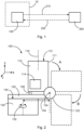
- Fig. 1 shows a schematic representation of an optical communication unit 100 and a remote station 200.
- the optical communication unit 100 and the remote station 200 represent end points of a communication connection.
- Communication signals 210, 220 can be transmitted wirelessly between these two end points.
- the communication signals are transmitted, for example, via a channel, with the dashed arrows pointing in both directions between the optical communication unit 100 and the remote station 200 symbolizing a bidirectional data exchange.
- the person skilled in the art can use all known transmission methods in connection with the optical communication unit 100 and the remote station 200 described here.
- the communication signals 210, 220 are transmitted wirelessly and optically between the optical communication unit 100 and the remote station 200 in the example described here.
- the optical communication unit 100 is arranged on board a satellite 10 and is designed to communicate with a counterpart 200 which is arranged in another aircraft or spacecraft or on the earth's surface (static or mobile).
- the in Fig. 1 The configuration shown may also be referred to as a communication system.
- the remote station may be configured in any manner known to those skilled in the art.
- the optical unit of the optical communication unit may be aligned with the remote station 200 in accordance with the principles described herein and may maintain this alignment to enable an exchange of optical communication signals 210, 220 between the optical communication unit and the remote station.
- Fig. 2 shows a schematic representation of an optical communication unit 100.
- the optical communication unit 100 in this example has an optical unit 110, an elevation drive 120 and an azimuth drive 130.
- the optical unit 110 has a housing 111 with an inlet/outlet opening 112 and optical components 114 arranged in the housing 111.
- the optical components 114 are, for example, conventional components used in optical data transmission, which emit an optical signal in the direction of a counterpart and/or receive an optical signal transmitted by a counterpart.
- the optical unit 110 is coupled to an elevation bearing 122, which enables the optical unit 110 to be pivoted about an elevation axis 124.
- the elevation axis 124 runs along the Y-axis.
- the pivoting movement about the elevation axis 124 is schematically indicated by in different positions and after pivoting movements A and B about positions of the optical unit 110 shown at 90° each, wherein the optical unit 110 is shown in dashed lines in these positions.
- the opening 112 In the initial position of the optical unit 110, the opening 112 points upwards. After the pivoting movement A by 90° clockwise, the opening 112 points to the right and after the further pivoting movement B by 90° clockwise, the opening 112 points downwards.
- the optical communication unit 100 described herein can enable a large angular range for the pivoting movement about the elevation axis 124.
- the optical unit 110 In the Fig. 2 In the example shown, the optical unit 110 is characterized by an angular range of 180° for the pivoting movement about the elevation axis 124.
- the optical unit 110 can also be connected to the elevation bearing 122 in such a way that the opening 112 in the initial position points in the direction of the elevation drive 120.
- Such a structure can help to protect the opening 112 and the optical components 114 from the ingress of foreign particles.
- the optical unit 110 rests on a holding and locking unit 126 or is mechanically coupled to it.
- the optical unit 110 is not only held by the elevation bearing 122, but also by the holding and locking unit 126.
- the holding and locking unit 126 can, for example, engage in the housing 111 of the optical unit 110 so that the optical unit 110 is firmly connected to the holding and locking unit 126 and is held in the initial position even when external forces act, for example in the launch phase of the satellite in which the optical communication unit 100 is installed.
- a central axis 116 or optical axis runs parallel to the Z axis.
- the elevation drive 120 is connected to the elevation bearing 122 so that the elevation drive 120 can transmit a force to the optical unit 110 to pivot the optical unit 110 about the elevation axis 124.
- the optical unit 110 is mounted on the elevation drive 120.
- the elevation drive 120 is in turn mounted on a support surface 134 of the azimuth drive 130.
- the azimuth drive 130 is designed to perform a rotational movement about the azimuth axis 132, wherein the azimuth axis 132 runs parallel to the Z axis.
- the support surface 134 also rotates accordingly and transmits this rotational movement to the optical unit 110.
- the elevation axis 124 is shown offset by a lateral offset 150 from the azimuth axis 132. If the optical unit 110 pivots clockwise from the initial position about the elevation axis 124, this pivoting movement can cover an angle greater than 90°. Even if the optical unit 110 has been pivoted at least partially laterally next to the support surface 134 of the azimuth drive 130 (i.e. into a position whose pivot angle is greater than the angle in position A, i.e. 90° starting from the initial position, and less than or equal to the pivot angle in position B, i.e. 180° starting from the initial position), a rotational movement about the azimuth axis 132 can still be carried out.
- the structure of the optical communication unit described here serves the flexible and compact design of optical transmitting and receiving units for satellites, in particular satellites that can be advantageously used in satellite constellations.
- the exceptional design of the rotation (rotation around the azimuth axis) and tilting mechanisms (swivel movement around the Elevation axis) enables a rotation range around the Z axis of up to 360° and a tilt range around the X or Y axis of up to 180° from its initial position.
- the upright position of the optical unit 110 in the initial position ensures optimal load introduction of the take-off loads, which makes the optical communication unit 100 described here suitable for a large number of mission profiles.
- the optical communication unit is characterized in particular by the eccentric suspension of the elevation bearing.
- the positioning of the elevation bearing at a distance of more than half the radius of the support surface 134 in relation to the azimuth axis enables high flexibility and - in conjunction with the holding and locking unit 126 - offers good introduction of the take-off loads into the structure, while at the same time ensuring a high deflection angle of the optical unit.
- the large tilt and rotation range enables an equally large effective field of view (angle range in which an optical connection to a remote station can be established) while maintaining a compact design.
- Fig. 3 shows a top view of the optical communication unit 100 with the optical unit 110 in the initial position.
- the inlet/outlet opening 112 of the housing of the optical unit 110 is shown in the middle.
- the opening 112 can have a diameter which is smaller than the diameter of the housing of the optical unit, but the opening 112 can also extend over an entire front surface of the housing of the optical unit. Even if the housing of the optical unit is shown as circular here, the housing of the optical unit can also have other shapes.
- the azimuth drive 130 When the azimuth drive 130 performs a rotary movement about the azimuth axis 132, the elevation drive 120, the elevation bearing 122 and the optical unit 110 are rotated during this rotary movement.
- the rotational movement can also be carried out when the optical unit 110 is not in the initial position, but is pivoted next to the azimuth drive 130. This is because the elevation axis 124 is offset by a lateral offset 150 from the azimuth axis 132.
- Fig. 4 shows a further schematic representation of the optical communication unit 100 with the already in Fig. 1 Components shown and described with reference to them. The components already in Fig. 1 The components shown will not be discussed again here.
- the optical combination unit 100 further comprises a processing unit 140, which is connected to the optical unit 110 by a first signal transmission medium 142 and a second signal transmission medium 144.
- the processing unit 140 can, for example, comprise processors, microcontrollers and other electronic components which carry out signal processing, signal conditioning and/or signal amplification functions.
- the signal transmission media 142, 144 are, for example, optical transmission media or glass fibers.
- the signal transmission media 142, 144 are preferably guided along the azimuth axis 132 or the elevation axis 124 to the optical unit 110. This keeps the mechanical load on the signal transmission media low during the rotation and pivoting movement of the optical unit 110.
- Fig. 5 shows an alternative structure of an optical communication unit 100, wherein the orientation of the optical unit 110 in the initial position differs from the orientation of the optical unit 110 Fig. 2
- the orientation of the optical unit 110 in the initial position differs from the orientation of the optical unit 110 Fig. 2
- the central axis or optical axis 116 of the optical unit 110 is in Fig. 5 compared to the example from Fig. 2 rotated by 90° and runs in the coordinate system of the Fig. 2 parallel to the X-axis. Also in the example of Fig. 5 Depending on the positioning of the elevation bearing 122, a swivel range of the optical unit 110 of up to 180° is possible. In the initial position, the housing 111 of the optical unit rests with one side surface on the holding and locking unit 126, whereas the optical unit 110 in the Fig. 2 with a base surface resting on the holding and locking unit and being coupled or locked thereto.
- the example in Fig. 5 has the advantage that the optical communication unit 100 takes up less space in the initial position.
- the different orientation of the optical unit in the initial position allows the opening 112 in the housing 111 to be positioned such that fewer foreign particles penetrate into the opening 112 during a launch phase of the satellite. This can help to reduce the impact on the emitted or received optical signals.
- Fig. 6 shows an optical combination unit 100, in which the possible advantageous positions of the elevation bearing are indicated in this illustration.
- the elevation bearing 122 initially has a lateral offset 150 to the azimuth axis 132.
- This lateral offset 150 (distance along the X-axis) is in an advantageous example greater than or equal to half the radius 136 of the support surface 134.
- the elevation bearing 122 can be offset laterally to such an extent that it partially or completely protrudes laterally beyond the support surface 134.
- the elevation bearing 122 is in the illustration of the Fig. 6 connected to the bottom right corner of the optical unit housing. However, this is not the only possible position to connect the elevation bearing to the optical unit housing. Rather, the elevation bearing can be connected to the housing along the Z axis over the entire extension of the housing.
- the compact design of the optical communication unit 100 described herein significantly reduces the number of components, which is reflected in a significant saving in mass and costs.
- pivoting mirrors arranged outside the optical unit are dispensed with because the entire optical unit 110 is rotatable and pivotable. Nevertheless, a large pivoting range around the elevation axis of up to 180° and a rotation range around the azimuth axis of up to 360° are possible.
Landscapes
- Physics & Mathematics (AREA)
- Electromagnetism (AREA)
- Engineering & Computer Science (AREA)
- Computer Networks & Wireless Communication (AREA)
- Signal Processing (AREA)
- Astronomy & Astrophysics (AREA)
- General Physics & Mathematics (AREA)
- Optics & Photonics (AREA)
- Optical Communication System (AREA)
- Input Circuits Of Receivers And Coupling Of Receivers And Audio Equipment (AREA)
- Fittings On The Vehicle Exterior For Carrying Loads, And Devices For Holding Or Mounting Articles (AREA)
Description
- Die vorliegende Beschreibung betrifft eine Kommunikationseinheit sowie deren Bewegungsmechanik für eine Schwenkbewegung um eine Elevationsachse und eine Drehbewegung um eine Azimutachse. Weiterhin betrifft die Beschreibung einen Kommunikationssatelliten mit einer solchen Kommunikationseinheit.
- Satellitenkonstellationen finden in jüngster Zeit zunehmend Verbreitung. Eine Satellitenkonstellation kann als Satellitenverbund mit einer Mehrzahl von Satelliten beschrieben werden, wobei die Satelliten jeweils auf einem vorgegebenen Orbit die Erde umkreisen und eine bestimmte Fläche der Erdoberfläche abdecken. Die Anzahl der Satelliten in einer Satellitenkonstellation und der Verlauf der Erdorbits kann so bemessen sein, dass mindestens ein Satellit eine optische Direktverbindung zu einem beliebigen Punkt auf der Erdoberfläche und zu jedem Zeitpunkt herstellen kann.
- Mit der zunehmenden Verbreitung von Satellitenkonstellationen im niedrigen und mittleren Erdorbit wandeln sich die Anforderungen an die von den Satelliten mitgeführte Nutzlast hin zu niedrigen Kosten und höheren Stückzahlen, was letztlich die Forderung nach einem niedrigeren Gewicht und einer reduzierten funktionalen und strukturellen Komplexität bei gleichzeitigem Beibehalten der Anforderungen an die Datenübertragung (insbesondere hohe Datenraten, möglichst großer Schwenkbereich und genaue Einstellbarkeit der Kommunikationseinheiten) bedeutet.
-
DE 10 2016 121 919 A1 beschreibt eine Satellitenkonstellation mit einer Mehrzahl von Kommunikationssatelliten sowie einen Ansatz der Datenübertragung und Routing zwischen den einzelnen Kommunikationssatelliten. -
DE 10 2017 127 813 A1 beschreibt ein System und ein Verfahren zum Einstellen einer Abstrahlrichtung eines optischen Kommunikationssignals zwischen einer Kommunikationsplattform und einer Gegenstelle. - Kesner Jessica E. et al.: "Compact optical gimbal as a conformal beam director for large field-of-regard lasercom applications", Proceedings of SPIE, IEEE, US, Vol. 9354, 93540K-1 bis 93540K-10 beschreibt eine Schwenkvorrichtung für eine optische Sende-/Empfangseinheit. Die Sende-/Empfangseinheit ist mit einem Schwenkantrieb (Elevationsantrieb) auf einem Drehtisch angeordnet. Der Elevationsantrieb kann radial versetzt werden, und zwar an verschiedene Positionen zwischen dem Mittelpunkt des Drehtisches und dem äußeren Rand des Drehtisches.
-
JP 2 806 659 B2 -
US 6 259 415 beschreibt ein Antennensystem mit einer Antenne, die auf einem Drehtisch gelagert ist und um eine Azimutachse und eine Elevationsachse geschwenkt werden kann. -
JP H08 288 732 A - Für die Übertragung von Daten können Kommunikationseinheiten verschiedenster Art verwendet werden. Kommunikationseinheiten nutzen allgemein elektromagnetische Signale für die Datenübertragung. Optische Kommunikationseinheiten beispielsweise bestehen aus mehreren Komponenten, welche die Aufgabe haben, das optische Signal auszurichten und nachzuführen (beispielsweise durch Umlenkspiegel oder eine Bewegung der optischen Einheit selbst), optische Signale aufzubereiten (durch eine optische Einheit), Daten zu verarbeiten (durch eine elektronische Einheit), und die Kommunikationseinheit zu steuern. Es können jedoch auch Richtantennen verwendet werden, deren Abstrahl- und Empfangsrichtung auf eine Gegenstelle ausgerichtet werden kann.
- Optische Signale können beispielsweise durch mehrere Spiegelelemente, welche jeweils um unterschiedlich angeordnete Achsen schwenkbar sind, von einer Gegenstelle auf die optische Einheit (oder umgekehrt) lenken. Hierbei ist die optische Einheit selbst, als Quelle oder Senke der optischen Signale, unbeweglich, jedoch lenken die Spiegel die optischen Signale um. Dieser Aufbau hat den Nachteil, dass die Mechanik sehr komplex ist und viel Platz erfordert sowie ein vergleichsweise hohes Gewicht hat.
- Eine andere Möglichkeit ist, die optische Einheit, welche auch als Teleskop bezeichnet werden kann, zu schwenken. Herkömmliche Aufbauten haben jedoch einen vergleichsweise kleinen Schwenkbereich des Teleskops um die Elevationsachse.
- Noch eine andere Möglichkeit ist unter dem Begriff "Coudé-Teleskop" bekannt. Hierbei wird der optische Freistrahl mittels eines Umlenkspiegels durch die Elevationsachse gelenkt und außerhalb des schwenkbaren Teleskops fokussiert.
- Es kann als Aufgabe betrachtet werden, eine Kommunikationseinheit anzugeben, welche sich durch eine kompakte und platzsparende Konstruktion und gleichzeitig einen großen Schwenkbereich um die Elevationsachse und einen großen Drehbereich um die Azimutachse auszeichnet.
- Diese Aufgabe wird gelöst durch den Gegenstand des unabhängigen Anspruchs. Weitere Ausführungsformen ergeben sich aus den abhängigen Ansprüchen sowie aus der folgenden Beschreibung.
- Gemäß einem ersten Aspekt ist eine Kommunikationseinheit zum Senden und Empfangen von Kommunikationssignalen angegeben. Die Kommunikationseinheit weist eine Sende-/Empfangs-Einheit, einen Elevationsantrieb und einen Azimutantrieb auf. Die Sende-/Empfangs-Einheit ist ausgestaltet, Kommunikationssignale zu emittieren und/oder zu empfangen. Der Elevationsantrieb ist über ein Elevationslager mit der Sende-/Empfangs-Einheit gekoppelt und ist ausgeführt, die Sende-/Empfangs-Einheit um eine Elevationsachse des Elevationslagers zu schwenken. Der Azimutantrieb ist mit der Sende-/Empfangs-Einheit und dem Elevationsantrieb gekoppelt und ist ausgeführt, die Sende-/Empfangs-Einheit samt Elevationsantrieb um eine Azimutachse zu drehen. Die Elevationsachse ist mit Bezug auf die Azimutachse exzentrisch angeordnet, so dass die Elevationsachse zu der Azimutachse um einen lateralen Versatz versetzt ist. Der Azimutantrieb weist eine Stützfläche auf, mit welcher der Elevationsantrieb und die Sende-/Empfangs-Einheit gekoppelt ist. Der Azimutantrieb ist ausgeführt, die Stützfläche bei der Drehbewegung um die Azimutachse zu drehen. Die Elevationsachse ist soweit von der Azimutachse lateral versetzt, dass die Elevationsachse lateral außerhalb der Stützfläche angeordnet ist. Das Elevationslager ist an einer Position mit einem Gehäuse der Sende-/Empfangs-Einheit verbunden, dass die Sende-/Empfangs-Einheit vollständig neben den Azimutantrieb und die Stützfläche schwenkbar ist.
- Die Sende-/Empfangs-Einheit kann beispielsweise eine optische Einheit in Form eines Teleskops sein, welches Linsen und/oder Spiegel sowie Sender und Empfänger für optische Signale aufweist. In dem Fall wird die Sende-/EmpfangsEinheit als optische Einheit bezeichnet. Die optische Einheit kann eine Sendepfad zum Senden von optischen Signalen und einen Empfangspfad zum Empfangen von optischen Signalen implementieren. Im Sendepfad wird die optische Einheit mit Signalen versorgt, welche in der optischen Einheit ggf. verarbeitet werden, um dann als optische Signale leitungslos übertragen zu werden. Im Empfangspfad erhält die optische Einheit optische Signale über einen leitungslosen Übertragungsweg, verarbeitet oder bearbeitet diese Signale, um sie dann in ein Signalübertragungsmedium einzuspeisen, wo das eingespeiste Signal leitungsgebunden übertragen wird.
- Die Sende-/Empfangs-Einheit kann aber auch als eine Richtantenne mit vorgebbarer Sende- und Empfangsrichtung ausgestaltet sein, wobei die Richtantenne so schwenkbar ist, wie dies für die optische Sende-/EmpfangsEinheit beschrieben wird.
- Aus Veranschaulichungszwecken wird im Folgenden insbesondere auf optische Kommunikationseinheiten mit optischen Einheiten Bezug genommen. Es wird jedoch darauf hingewiesen, dass die vorliegende Beschreibung sowohl für optische Einheiten als auch für eine Richtantenne oder jede andere Sende-/Empfangs-Einheit mit einer vorgebbaren und gerichteten Sende- und Empfangsrichtung gilt. Das bedeutet insbesondere, dass jegliche Bezugnahmen in der Beschreibung auf eine optische Einheit und auf eine optische Kommunikationseinheit lediglich als Beispiel zu verstehen sind und in analoger Weise für Kommunikationseinheiten mit anderen Signalträgern (elektromagnetische Wellen) in Form von beispielsweise Richtantennen gelten.
- Die Elevationsachse erstreckt sich quer zu der Azimutachse, insbesondere senkrecht dazu. Der Elevationsantrieb ist mechanisch mit der Sende-/EmpfangsEinheit gekoppelt und dient dazu, die Sende-/Empfangs-Einheit um die Elevationsachse zu schwenken. Der Elevationsantrieb kann beispielsweise ein elektrisch betriebener Motor sein, beispielsweise ein Schrittmotor, welcher direkt oder über ein Getriebe mit der Sende-/Empfangs-Einheit verbunden ist, um eine Bewegung des Motors auf die Sende-/Empfangs-Einheit zu übertragen und die Sende-/Empfangs-Einheit um die Elevationsachse zu schwenken. Je nach Bewegungsrichtung des Motors oder Einstellung des Getriebes kann die Sende-/Empfangs-Einheit die Schwenkbewegung um die Elevationsachse in beide möglichen Richtungen ausführen.
- Der Azimutantrieb kann ebenfalls ein elektrisch betriebener Antrieb wie der Elevationsantrieb sein. Der Azimutantrieb kann beispielsweise als Drehteller ausgestaltet sein, welcher den Elevationsantrieb und die Sende-/EmpfangsEinheit trägt. Der Azimutantrieb kann dabei mit Hilfe des elektrisch betriebenen Antriebs eine Drehbewegung um die Azimutachse ausführen. Bei dieser Drehbewegung wird die Sende-/Empfangs-Einheit und der Elevationsantrieb durch die Bewegung des Drehtellers um die Azimutachse geführt.
- Der Azimutantrieb und der Elevationsantrieb werden von einer externen Steuerung angesteuert, um eine Position anzufahren, welche durch einen Azimut- und Elevationswinkel definiert ist. Diese Position wird durch die relative Anordnung einer Kommunikationsgegenstelle vorgegeben, auf welche die Sende-/EmpfangsEinheit ausgerichtet werden muss, um das Senden und Empfangen von Kommunikationssignalen zu ermöglichen. Auf die Steuerung des Azimutantriebs und des Elevationsantriebs wird vorliegend nicht näher eingegangen. Hierfür greift der Fachmann auf bekannte Mechanismen zurück. Maßgeblich ist, dass mit der hier beschriebenen Struktur der Kommunikationseinheit durch einen einfachen Aufbau ein großer Drehbereich um die Azimutachse und ein großer Schwenkbereich um die Elevationsachse ermöglicht wird. Wenn die Kommunikationseinheit an Bord eines Kommunikationssatelliten verwendet wird, kann die Sende-/Empfangs-Einheit während eines Orbitalflugs des Kommunikationssatelliten wahlweise auf eine Gegenstelle ausgerichtet und in dieser Orientierung gehalten werden.
- Die Elevationsachse ist mit Bezug auf die Azimutachse lateral versetzt. Dies ermöglicht es, dass die Sende-/Empfangs-Einheit bei einer Schwenkbewegung um die Elevationsachse soweit in Richtung des Azimutantriebs geschwenkt werden kann, dass die Sende-/Empfangs-Einheit mindestens teilweise seitlich neben dem Azimutantrieb liegt. Somit wird ermöglicht, einen Schwenkbereich der Sende-/Empfangs-Einheit um die Elevationsachse zu vergrößern. Die physischen Dimensionen des Azimutantriebs bzw. des Drehtellers bilden damit zwar weiterhin eine natürliche Begrenzung des Schwenkbereichs um die Elevationsachse, allerdings wird der Schwenkbereich der Sende-/Empfangs-Einheit um die Elevationsachse durch den lateralen Versatz der Elevationsachse mit Bezug auf die Azimutachse oder den Azimutantrieb vergrößert.
- Wenn die Sende-/Empfangs-Einheit um die Elevationsachse schwenkt, führt die Sende-/Empfangs-Einheit mit Bezug zu dem Azimutantrieb bzw. dem zugehörigen Drehteller nicht nur eine Rotationsbewegung aus, sondern die Sende-/EmpfangsEinheit insgesamt führt eine entlang eines Kreisbogens um die Elevationsachse verlaufende kombinierte rotatorische und translatorische Bewegung mit Bezug zu dem Drehteller des Azimutantriebs aus. Auch wenn die Elevationsachse an sich ihre Position nicht verändert, so führt ein geometrischer Mittelpunkt der Sende-/Empfangs-Einheit diese besagte kombinierte rotatorische und translatorische Bewegung aus. In anderen Worten: während die Sende-/Empfangs-Einheit um die Elevationsachse schwenkt, erfährt sie eine laterale Versatzbewegung und kann damit bei fortgeführter Schwenkbewegung neben den Drehteller schwenken, was den möglichen Schwenkbereich um die Elevationsachse vergrößert.
- Der hier beschriebene Aufbau ermöglicht eine Drehbewegung um die Azimutachse von bis zum 360° und eine Schwenkbewegung um die Elevationsachse von bis zu 180°. Weiterhin ermöglicht es der hier beschriebene Aufbau, im Falle einer optischen Einheit auf eine komplexe bewegliche Spiegelmechanik außerhalb der Sende-/Empfangs-Einheit zu verzichten, weil die Sende-/Empfangs-Einheit an sich bewegt wird und die Bewegung der Sende-/Empfangs-Einheit durch die hier beschriebene Anordnung der Elevationsachse bezogen auf die Azimutachse einen großen Schwenkbereich um die Elevationsachse und einen großen Drehbereich um die Azimutachse ermöglicht.
- In einer Ausführungsform ist das Elevationslager mit einem Gehäuse der Sende-/Empfangs-Einheit verbunden und die Elevationsachse ist mit Bezug zu einer Mittelachse des Gehäuses exzentrisch angeordnet.
- Die Sende-/Empfangs-Einheit weist ein Gehäuse auf, in welchem optische und/oder elektrische Bauteile angeordnet sind, welche die Kommunikationssignale emittieren und/oder empfangen. Die Kommunikationssignale verlassen das Gehäuse durch eine Ein-/Auslassöffnung bzw. dringen durch die Ein-/Auslassöffnung in das Gehäuse ein und treffen dann auf die entsprechenden Bauteile. Wenn die Sende-/Empfangs-Einheit um die Elevationsachse geschwenkt und/oder um die Azimutachse gedreht wird, betrifft die jeweilige Bewegung oder auch kombinierte Schwenk-/Drehbewegung das gesamte Gehäuse der Sende-/Empfangs-Einheit. Demnach ist das Elevationslager mit dem Gehäuse der Sende-/Empfangs-Einheit mechanisch verbunden. Eine Mittelachse des Gehäuses verläuft beispielsweise in derjenigen Richtung, in welcher die Kommunikationssignale die Sende-/Empfangs-Einheit verlassen und erstreckt sich zentral durch das Gehäuse, d.h. mittig bezogen auf die links-rechts-Ausdehnung des Gehäuses (die links-rechts-Ausdehnung ist definiert als Richtung auf die Elevationsachse zu bzw. hiervon weg). Mit Bezug auf diese Mittelachse ist das Elevationslager exzentrisch an dem Gehäuse der Sende-/Empfangs-Einheit angeordnet.
- Das Elevationslager ist beispielsweise in einem Eck des Gehäuses angeordnet. Andere mögliche Positionen des Elevationslagers werden weiter unten beschrieben. In dieser Ausführungsform ist die Elevationsachse exzentrisch mit Bezug auf die Mittelachse des Gehäuses angeordnet.
- In einer weiteren Ausführungsform weist der Azimutantrieb eine Stützfläche auf, mit welcher der Elevationsantrieb und die Sende-/Empfangs-Einheit gekoppelt sind, wobei der Azimutantrieb ausgeführt ist, die Stützfläche bei der Drehbewegung um die Azimutachse zu drehen.
- Die Stützfläche kann als Drehtisch bezeichnet werden, auf welchem oder an welchem der Elevationsantrieb und/oder die Sende-/Empfangs-Einheit angeordnet und hiermit verbunden sind. Der Azimutantrieb dreht die Stützfläche um die Azimutachse. Dabei wird der Elevationsantrieb und die Sende-/Empfangs-Einheit in dieselbe Drehbewegung um die Azimutachse versetzt.
- Der Elevationsantrieb und die Sende-/Empfangs-Einheit sind entweder jeweils unmittelbar oder mittelbar mit der Stützfläche verbunden. Beispielsweise kann der Elevationsantrieb unmittelbar mit der Stützfläche verbunden sein und die Sende-/Empfangs-Einheit ist ihrerseits unmittelbar mit dem Elevationsantrieb verbunden, womit die Sende-/Empfangs-Einheit mittelbar mit der Stützfläche verbunden ist. Jedenfalls resultiert eine Drehbewegung der Stützfläche in einer entsprechenden Bewegung des Elevationsantriebs sowie der Sende-/Empfangs-Einheit um die Azimutachse.
- Bevorzugt definiert die Stützfläche den äußeren Umfang des Azimutantriebs, d.h. die Komponenten des Azimutantriebs befinden sich unterhalb der Stützfläche und ragen nicht seitlich über den äußeren Rand der Stützfläche hinaus.
- Die Stützfläche kann beispielsweise kreisrund sein. Somit kann die Sende-/Empfangs-Einheit auch um die Azimutachse gedreht werden, wenn die Sende-/Empfangs-Einheit soweit um die Elevationsachse geschwenkt ist, dass die Sende-/Empfangs-Einheit teilweise seitlich neben der Stützfläche platziert ist. Im Falle einer kreisrunden Stützfläche kann die Sende-/Empfangs-Einheit um 360° um die Azimutachse gedreht werden, ohne an die Stützfläche anzustoßen. Es ist aber auch denkbar, dass nur ein Bereich der Stützfläche einen Kreisbogen bildet, beispielsweise von 270°. Dann ist die Drehbewegung der Sende-/EmpfangsEinheit um die Azimutachse auf die besagten 270° des Kreisbogens der Stützfläche beschränkt, wenn die Sende-/Empfangs-Einheit um die Elevationsachse neben die Stützfläche geschwenkt ist.
- Nicht jeder laterale Versatz zwischen Elevationsachse und Azimutachse ermöglicht es notwendigerweise, dass die Sende-/Empfangs-Einheit vollständig neben die Stützfläche geschwenkt werden kann. Dass die Sende-/EmpfangsEinheit teilweise um die Stützfläche herum oder neben die Stützfläche geschwenkt werden kann, bedeutet, dass ein Schwenkbereich von größer als 90° ermöglicht wird.
- Erfindungsgemäß ist die Elevationsachse soweit von der Azimutachse lateral versetzt, dass die Elevationsachse lateral außerhalb der Stützfläche angeordnet ist.
- Damit liegt die Elevationsachse seitlich außerhalb der Stützfläche. Das Elevationslager ist an einer Position mit dem Gehäuse der Sende-/EmpfangsEinheit verbunden, dass die Sende-/Empfangs-Einheit vollständig neben den Azimutantrieb und den zugehörigen Drehtisch geschwenkt werden.
- In einer weiteren Ausführungsform weist die Kommunikationseinheit weiterhin eine Verarbeitungseinheit zum Verarbeiten von Kommunikationssignalen auf, wobei die Verarbeitungseinheit mittels eines Signalübertragungsmediums mit der Sende-/Empfangs-Einheit verbunden ist, so dass die von der Sende-/Empfangs-Einheit zu übertragenden und/oder empfangenen Kommunikationssignale zwischen der Verarbeitungseinheit und der Sende-/Empfangs-Einheit übertragen werden können.
- Die Verarbeitungseinheit führt beispielsweise Schritte der Signalverarbeitung und/oder Signalaufbereitung durch, beispielsweise Anpassung der Codierung, Verstärkung, etc. In der Verarbeitungseinheit können aber auch weitere Funktionen implementiert sein, welche eine inhaltliche Signalverarbeitung mit den zu übertragenden oder empfangenen Signalen ausführen.
- In einer weiteren Ausführungsform ist das Signalübertragungsmedium ausgeführt, Kommunikationssignale, insbesondere optische Signale, zu übertragen und verläuft mindestens abschnittsweise entlang der Azimutachse und/oder der Elevationsachse.
- Das Signalübertragungsmedium kann beispielsweise eine Glasfaserleitung sein. Die Glasfaserleitung verbindet die Verarbeitungseinheit und die Sende-/Empfangs-Einheit. Somit muss die Glasfaserleitung sowohl eine Drehbewegung der Sende-/Empfangs-Einheit um die Azimutachse als auch eine Schwenkbewegung um die Elevationsachse mitmachen. Indem die Glasfaserleitung entlang der Azimutachse und/oder der Elevationsachse verläuft, wird das Ausmaß der Biegungsmomente auf die Glasfaser reduziert. Durch die Dreh- und Schwenkbewegung in den beiden Achsen wird an diesen Stellen hauptsächlich ein Torsionsmoment auf die Glasfaser ausgeübt. Glasfaserleitungen sind typischerweise so ausgestaltet, dass Torsionsmomente mit einer niedrigen mechanischen Belastung der Glasfaser einhergehen, wohingegen Biegemomente die Glasfaser mechanisch deutlich stärker belasten. Indem die Glasfaserleitung entlang der Azimutachse und/oder Elevationsachse verläuft, wird dieser Erkenntnis Rechnung getragen und die mechanische Belastung der Glasfaser bei der Bewegung der Sende-/Empfangs-Einheit geringgehalten.
- In einer weiteren Ausführungsform weist die Kommunikationseinheit weiterhin eine Halte- und Verriegelungseinheit auf, wobei die Halte- und Verriegelungseinheit ausgeführt ist, die Sende-/Empfangs-Einheit in einer Initialposition zu verriegeln, so dass die Sende-/Empfangs-Einheit von einer Schwenkbewegung um die Elevationsachse und/oder von einer Drehbewegung um die Azimutachse abgehalten wird.
- Die Halte- und Verriegelungseinheit wird vorteilhaft verwendet, wenn die Kommunikationseinheit in einem Satelliten verwendet wird und die Sende-/Empfangs-Einheit während der Startphase des Satelliten auf dem Weg in ein Erdorbit fixiert werden muss, um unkontrollierte Bewegung der Sende-/EmpfangsEinheiten, die von den hohen Kräften in der Startphase verursacht werden können, zu vermeiden.
- Die Halte- und Verriegelungseinheit kann beispielsweise ein kombinierter Bolzen-Haken-Mechanismus sein, welcher die Sende-/Empfangs-Einheit mit dem Elevationsantrieb verbindet, um eine Schwenkbewegung um die Elevationsachse zu unterbinden, und welcher zusätzlich den Azimutantrieb verriegelt, um eine ungewollte Drehung um die Azimutachse zu unterbinden. Die Halte- und Verriegelungseinheit kann zusätzlich in das Gehäuse der optischen Einheit eingreifen, damit die Sende-/Empfangs-Einheit während der Startphase nicht nur von dem Elevationslager getragen oder gehalten wird, sondern zusätzlich von der Halte- und Verriegelungseinheit fixiert wird.
- Die Initialposition kann auch als Ausgangsposition oder Parkposition der Sende-/Empfangs-Einheit bezeichnet werden. Die Initialposition kann insbesondere eine Grenze der Schwenkbewegung um die Elevationsachse in einer Richtung bilden. D.h. dass die Sende-/Empfangs-Einheit ausgehend von der Initialposition nicht in beide Richtungen geschwenkt werden kann, sondern nur in eine Richtung weg von der Halte- und Verriegelungseinheit. Das bedeutet beispielsweise, dass die Sende-/Empfangs-Einheit in der Initialposition und in dem verriegelten Zustand der Halte- und Verriegelungseinheit keine Schwenkbewegung um das Elevationslager ausführen kann und dementsprechend kein Drehmoment auf das Elevationslager wirkt, sondern das Elevationslager höchstens Stützkräfte aufbringen muss, um die Sende-/Empfangs-Einheit in der Initialposition zu halten. Dies kann dazu beitragen, die mechanische Belastung des Elevationslagers gering zu halten.
- In einer weiteren Ausführungsform ist die Sende-/Empfangs-Einheit in einer Initialposition so ausgerichtet, dass eine Abstrahlrichtung der Kommunikationssignale durch eine Ein-/Auslassöffnung der Sende-/EmpfangsEinheit parallel oder senkrecht zu der Azimutachse verläuft.
- Es kann gewünscht sein, dass die Ein-/Auslassöffnung des Gehäuses der Sende-/Empfangs-Einheit in der Initialposition eine bestimmte Orientierung mit Bezug zu dem Satelliten aufweist, beispielsweise um das Eindringen von Fremdpartikeln in die Sende-/Empfangs-Einheit während der Startphase des Satelliten zu verhindern oder das Ausmaß hiervon zu reduzieren. Das Elevationslager kann so an dem Gehäuse der Sende-/Empfangs-Einheit angeordnet sein, dass die Ein-/Auslassöffnung in der Initialposition wunschgemäß angeordnet ist. Die Abstrahlrichtung der Kommunikationssignale durch die Ein-/Auslassöffnung des Gehäuses der Sende-/Empfangs-Einheit kann parallel zu der bereits genannten Mittelachse des Gehäuses verlaufen.
- Gemäß einem weiteren Aspekt ist ein Kommunikationssatellit angegeben, welcher eine Kommunikationseinheit wie hierin beschrieben aufweist.
- Die Kommunikationseinheit kann vorteilhaft als Sender und/oder Empfänger von elektromagnetischen oder optischen Kommunikationssignalen in einem Kommunikationssatelliten verwendet werden. Die Sende-/Empfangs-Einheit wird um die Azimutachse gedreht und/oder um die Elevationsachse geschwenkt, um die Sende-/Empfangs-Einheit auf eine Gegenstelle auszurichten, damit ein Kommunikationssignal zu der Gegenstelle gesendet oder von dieser empfangen werden kann.
- Der hier beschriebene Aufbau der Kommunikationseinheit ermöglicht ein gutes Nachführen und Ausrichten der Sende-/Empfangs-Einheit bezogen auf die Gegenstelle, weil ein großer Schwenkbereich um die Elevationsachse und ein großer Drehbereich um die Azimutachse ermöglicht wird und gleichzeitig eine geringe Anzahl von Komponenten sowie ein einfacher mechanischer Aufbau verwendet wird.
- Unter einem Kommunikationssatelliten wird vorliegend ein Raumfahrzeug verstanden, welches sich mindestens zeitweise über der Erdoberfläche bewegt oder in einer Erdumlaufbahn befindet oder dafür vorgesehen ist, über der Erdoberfläche oder in einer Erdumlaufbahn eingesetzt zu werden, wobei dieses Raumfahrzeug eine Kommunikationseinrichtung an Bord aufweist, welche den Signalaustausch mit einer Gegenstelle auf der Erde oder über der Erdoberfläche, beispielsweise an Bord eines anderen Kommunikationssatelliten oder Luft- oder Raumfahrzeugs, ermöglicht. Der Begriff des Kommunikationssatelliten wird also funktional definiert, dahingehend dass es sich um ein Raumfahrzeug handelt, welches eine Kommunikationseinrichtung zum Austausch von Kommunikationssignalen an Bord hat. Bevorzugt ist der Kommunikationssatellit ausgestaltet, dass es einen längeren Zeitraum von einigen Jahren in einem Erdorbit verwendet wird und die Erde auf einer vorgegebenen Umlaufbahn umkreist. Während der Bewegung des Kommunikationssatelliten auf seiner Umlaufbahn kann die Sende-/Empfangs-Einheit der Kommunikationseinheit auf eine Gegenstelle ausgerichtet und der Gegenstelle nachgeführt werden. Der Aufbau der Kommunikationseinheit ermöglicht einen großen Schwenkbereich trotz eines einfachen mechanischen Aufbaus und eines damit einhergehenden geringen Gewichts.
- Nachfolgend wird anhand der beigefügten Zeichnungen näher auf Ausführungsbeispiele eingegangen. Die Darstellungen sind schematisch und nicht maßstabsgetreu. Gleiche Bezugszeichen beziehen sich auf gleiche oder ähnliche Elemente. Es zeigen:
- Fig. 1
- eine schematische Darstellung eines Kommunikationssatelliten und einer Gegenstelle gemäß einem Ausführungsbeispiel.
- Fig. 2
- eine schematische Darstellung einer optischen Kommunikationseinheit gemäß einem Ausführungsbeispiel in einer Seitenansicht.
- Fig. 3
- eine schematische Darstellung einer optischen Kommunikationseinheit gemäß einem Ausführungsbeispiel in einer Draufsicht.
- Fig. 4
- eine schematische Darstellung einer optischen Kommunikationseinheit gemäß einem Ausführungsbeispiel in einer Seitenansicht.
- Fig. 5
- eine schematische Darstellung einer optischen Kommunikationseinheit gemäß einem Ausführungsbeispiel in einer Seitenansicht.
- Fig. 6
- eine schematische Darstellung einer optischen Kommunikationseinheit gemäß einem Ausführungsbeispiel in einer Seitenansicht.
- Die Beispiele in den Figuren werden mit Bezugnahme auf eine optische Kommunikationseinheit 100 mit einer optischen Einheit 110 beschrieben. Die hier dargelegten Prinzipien gelten jedoch auch für andere Sende-/Empfangs-Einheiten, welche allgemein elektromagnetische Signale für die Signalübertragung nutzen und sind nicht auf optische Einheiten beschränkt.
-
Fig. 1 zeigt eine schematische Darstellung einer optischen Kommunikationseinheit 100 und einer Gegenstelle 200. Die optische Kommunikationseinheit 100 und die Gegenstelle 200 stellen Endpunkte einer Kommunikationsverbindung dar. Zwischen diesen beiden Endpunkten können Kommunikationssignale 210, 220 leitungslos übertragen werden. Die Kommunikationssignale werden beispielsweise über einen Kanal übertragen, wobei die zwischen der optischen Kommunikationseinheit 100 und der Gegenstelle 200 in beide Richtungen weisenden gestrichelten Pfeile einen bidirektionalen Datenaustausch symbolisieren sollen. Der Fachmann kann im Zusammenhang mit der hier beschriebenen optischen Kommunikationseinheit 100 und der Gegenstelle 200 auf sämtliche bekannten Übertragungsverfahren zurückgreifen. Die Kommunikationssignale 210, 220 werden zwischen der optischen Kommunikationseinheit 100 und der Gegenstelle 200 in dem hier beschriebenen Beispiel leitungslos und optisch übertragen. - Die optische Kommunikationseinheit 100 ist an Bord eines Satelliten 10 angeordnet und ist dafür ausgelegt, mit einer Gegenstelle 200 zu kommunizieren, welche in einem anderen Luftfahrzeug oder Raumfahrzeug oder auf der Erdoberfläche (statisch oder mobil) angeordnet ist.
- Die in
Fig. 1 gezeigte Konfiguration kann auch als Kommunikationssystem bezeichnet werden. Die Gegenstelle kann auf jegliche dem Fachmann bekannte Weise ausgestaltet sein. Während der Satellit 10 seiner vorgegebenen Umlaufbahn um die Erde folgt, kann die optische Einheit der optischen Kommunikationseinheit gemäß den hierin beschriebenen Prinzipien auf die Gegenstelle 200 ausgerichtet werden und diese Ausrichtung beibehalten, um einen Austausch von optischen Kommunikationssignalen 210, 220 zwischen der optischen Kommunikationseinheit und der Gegenstelle zu ermöglichen. -
Fig. 2 zeigt eine schematische Darstellung einer optischen Kommunikationseinheit 100. Die optische Kommunikationseinheit 100 weist in diesem Beispiel eine optische Einheit 110, einen Elevationsantrieb 120 und einen Azimutantrieb 130 auf. - Die optische Einheit 110 weist ein Gehäuse 111 mit einer Ein-/Auslassöffnung 112 und in dem Gehäuse 111 angeordneten optischen Bauteilen 114 auf. Die optischen Bauteile 114 sind beispielsweise übliche in der optischen Datenübertragung verwendete Bauteile, welche ein optisches Signal in Richtung einer Gegenstelle emittieren und/oder ein von einer Gegenstelle ausgesandtes optisches Signal empfangen.
- Die optische Einheit 110 ist mit einem Elevationslager 122 gekoppelt, welches es ermöglicht, dass die optische Einheit 110 um eine Elevationsachse 124 geschwenkt werden kann. Die Elevationsachse 124 verläuft entlang der Y-Achse. Die Schwenkbewegung um die Elevationsachse 124 ist schematisch angedeutet durch in verschiedenen Positionen und nach Schwenkbewegungen A und B um jeweils 90° gezeigten Positionen der optischen Einheit 110, wobei die optische Einheit 110 in diesen Positionen jeweils gestrichelt gezeichnet ist.
- In der Initialposition der optischen Einheit 110 weist die Öffnung 112 nach oben. Nach der Schwenkbewegung A um 90° im Uhrzeigersinn weist die Öffnung 112 nach rechts und nach der weiteren Schwenkbewegung B um 90° im Uhrzeigersinn weist die Öffnung 112 nach unten. Somit kann die hierin beschriebene optische Kommunikationseinheit 100 einen großen Winkelbereich für die Schwenkbewegung um die Elevationsachse 124 ermöglichen. In dem in
Fig. 2 gezeigten Beispiel zeichnet sich die optische Einheit 110 durch einen Winkelbereich von 180° für die Schwenkbewegung um die Elevationsachse 124 aus. - Die optische Einheit 110 kann aber auch so mit dem Elevationslager 122 verbunden sein, dass die Öffnung 112 in der Initialposition in Richtung des Elevationsantriebs 120 zeigt. Ein solcher Aufbau kann dazu beitragen, die Öffnung 112 und die optischen Bauteile 114 vor dem Eindringen von Fremdpartikeln zu schützen.
- In der Initialposition liegt die optische Einheit 110 auf einer Halte- und Verriegelungseinheit 126 auf bzw. ist mit dieser mechanisch gekoppelt. Somit wird die optische Einheit 110 in der Initialposition nicht nur von dem Elevationslager 122 gehalten, sondern auch von der Halte- und Verriegelungseinheit 126. Die Halte- und Verriegelungseinheit 126 kann beispielsweise in das Gehäuse 111 der optischen Einheit 110 eingreifen, damit die optische Einheit 110 fest mit der Halte- und Verriegelungseinheit 126 verbunden ist und auch beim Einwirken von äußeren Kräften, beispielsweise in der Startphase des Satelliten, in welchem die optische Kommunikationseinheit 100 eingebaut ist, in der Initialposition gehalten wird. In der Initialposition verläuft eine Mittelachse 116 bzw. optische Achse (die Richtung, in welcher optische Signale emittiert oder empfangen werden) parallel zu der Z-Achse.
- Der Elevationsantrieb 120 ist mit dem Elevationslager 122 verbunden, so dass der Elevationsantrieb 120 eine Kraft auf die optische Einheit 110 übertragen kann, um die optische Einheit 110 um die Elevationsachse 124 zu schwenken.
- Für einen platzsparenden Aufbau ist die optische Einheit 110 auf dem Elevationsantrieb 120 montiert. Der Elevationsantrieb 120 seinerseits ist auf einer Stützfläche 134 des Azimutantriebs 130 montiert. Der Azimutantrieb 130 ist ausgeführt, eine Rotationsbewegung um die Azimutachse 132 auszuführen, wobei die Azimutachse 132 parallel zu der Z-Achse verläuft. Im Falle einer Drehbewegung um die Azimutachse 132 dreht sich auch die Stützfläche 134 entsprechend und überträgt diese Drehbewegung auf die optische Einheit 110.
- Wie in
Fig. 2 gezeigt ist die Elevationsachse 124 um einen lateralen Versatz 150 von der Azimutachse 132 versetzt. Wenn die optische Einheit 110 aus der Initialposition im Uhrzeigersinn um die Elevationsachse 124 schwenkt, kann diese Schwenkbewegung einen Winkel größer als 90° abdecken. Selbst wenn die optische Einheit 110 mindestens teilweise seitlich neben die Stützfläche 134 des Azimutantriebs 130 geschwenkt wurde (also in eine Position, deren Schwenkwinkel größer als der Winkel in Position A, also 90° ausgehend von der Initialposition, und kleiner oder gleich dem Schwenkwinkel in Position B, also 180° ausgehend von der Initialposition, ist), kann noch eine Drehbewegung um die Azimutachse 132 ausgeführt werden. - Wie der
Fig. 2 entnommen werden kann, dient der hier beschriebene Aufbau der optischen Kommunikationseinheit der flexiblen und kompakten Auslegung von optischen Sende- und Empfangseinheiten für Satelliten, insbesondere von Satelliten, die vorteilhaft in Satellitenkonstellationen verwendet werden können. - Die außergewöhnliche Ausführung der Dreh- (Drehbewegung um die Azimutachse) und Kipp-Mechanismen (Schwenkbewegung um die Elevationsachse) ermöglicht einen Drehbereich um die Z-Achse von bis zu 360° sowie einen Kippbereich um die X oder Y-Achse von bis zu 180° von seiner Initialposition. Durch die aufrechte Position der optischen Einheit 110 in der Initialposition wird eine optimale Lasteinleitung der Startlasten gewährleistet, was die hier beschriebene optische Kommunikationseinheit 100 für eine große Anzahl von Missionsprofilen einsetzbar macht. Die optische Kommunikationseinheit zeichnet sich insbesondere durch die exzentrische Aufhängung des Elevationslagers aus. Die Positionierung des Elevationslagers in einem Abstand von mehr als der Hälfte des Radius der Stützfläche 134 bezogen auf die Azimutachse ermöglicht hohe Flexibilität und - im Zusammenspiel mit der Halte- und Verriegelungseinheit 126- bietet eine gute Einleitung der Startlasten in die Struktur, bei gleichzeitig hohem Auslenkungswinkel der optischen Einheit. Der große Kipp- und Drehbereich ermöglich ein ebenso großes effektives Sichtfeld (Winkelbereich, in welchem eine optische Verbindung zu einer Gegenstelle aufgebaut werden kann) bei gleichzeitig kompakter Bauweise.
-
Fig. 3 zeigt eine Draufsicht auf die optische Kommunikationseinheit 100 mit der optischen Einheit 110 in der Initialposition. In der Draufsicht auf die optische Kommunikationseinheit 100 ist mittig die Ein-/Auslassöffnung 112 des Gehäuses der optischen Einheit 110 gezeigt. Die Öffnung 112 kann einen Durchmesser haben, welcher kleiner als der Durchmesser des Gehäuses der optischen Einheit ist, jedoch kann sich die Öffnung 112 auch über eine gesamte Stirnfläche des Gehäuses der optischen Einheit erstrecken. Auch wenn das Gehäuse der optischen Einheit hier kreisförmig dargestellt ist, kann das Gehäuse der optischen Einheit auch andere Formen haben. Wenn die optische Einheit aus der Initialposition um die Elevationsachse 124 geschwenkt wird, bewegt sich die optische Einheit inFig. 3 nach rechts. Das Elevationslager 126 ist an dem Elevationsantrieb 120 befestigt. Der Elevationsantrieb 120 wiederum liegt auf dem Azimutantrieb 130 auf. Wenn der Azimutantrieb 130 eine Drehbewegung um die Azimutachse 132 ausgeführt, werden der Elevationsantrieb 120, das Elevationslager 122 und die optische Einheit 110 bei dieser Drehbewegung mitgeführt. Die Drehbewegung kann auch ausgeführt werden, wenn sich die optische Einheit 110 nicht in der Initialposition befindet, sondern neben den Azimutantrieb 130 geschwenkt ist. Dies liegt daran, dass die Elevationsachse 124 um einen lateralen Versatz 150 von der Azimutachse 132 versetzt ist. -
Fig. 4 zeigt eine weitere schematische Darstellung der optischen Kommunikationseinheit 100 mit den bereits inFig. 1 gezeigten und mit Bezug hierzu beschriebenen Komponenten. Auf die bereits inFig. 1 gezeigten Komponenten wird hier nicht erneut eingegangen. - Die optische Kombinationseinheit 100 weist in diesem Beispiel weiterhin eine Verarbeitungseinheit 140 auf, welche mit einem ersten Signalübertragungsmedium 142 und einem zweiten Signalübertragungsmedium 144 mit der optischen Einheit 110 verbunden ist. Die Verarbeitungseinheit 140 kann beispielsweise Prozessoren, Mikrocontroller und andere elektronische Bauteile aufweisen, welche Funktionen der Signalverarbeitung, Signalaufbereitung und/oder Signalverstärkung ausführen. Die Signalübertragungsmedien 142, 144 sind beispielsweise optische Übertragungsmedien bzw. Glasfasern. Bevorzugt werden die Signalübertragungsmedien 142, 144 entlang der Azimutachse 132 oder der Elevationsachse 124 auf die optische Einheit 110 geführt. Hierdurch wird die mechanische Belastung auf die Signalübertragungsmedien während der Dreh- und Schwenkbewegung der optischen Einheit 110 geringgehalten.
-
Fig. 5 zeigt einen alternativen Aufbau einer optischen Kommunikationseinheit 100, wobei sich die Orientierung der optischen Einheit 110 in der Initialposition von der Orientierung der optischen Einheit 110 ausFig. 2 unterscheidet. Für die Beschreibung der weiteren Komponenten wird auch die bisherigen Figuren verwiesen. - Die Mittelachse bzw. optische Achse 116 der optischen Einheit 110 ist in
Fig. 5 im Vergleich zu dem Beispiel ausFig. 2 um 90° gedreht und verläuft in dem Koordinatensystem derFig. 2 parallel zu der X-Achse. Auch in dem Beispiel derFig. 5 ist je nach Positionierung des Elevationslagers 122 eine Schwenkbereich der optischen Einheit 110 von bis zu 180° möglich. In der Initialposition liegt das Gehäuse 111 der optischen Einheit mit einer Seitenfläche auf der Halte- und Verriegelungseinheit 126 auf, wohingegen die optische Einheit 110 in derFig. 2 mit einer Bodenfläche auf der Halte- und Verriegelungseinheit aufliegt und hiermit gekoppelt bzw. verriegelt ist. - Das Beispiel in
Fig. 5 hat den Vorteil, dass die optische Kommunikationseinheit 100 in der Initialposition weniger Platz einnimmt. Außerdem kann durch die andersartige Orientierung der optischen Einheit in der Initialposition die Öffnung 112 in dem Gehäuse 111 so positioniert werden, dass weniger Fremdpartikel während einer Startphase des Satelliten in die Öffnung 112 eindringen. Dies kann dazu beitragen, die emittierten oder empfangenen optischen Signale weniger zu beeinträchtigen. -
Fig. 6 zeigt eine optische Kombinationseinheit 100, wobei in dieser Darstellung die möglichen vorteilhaften Positionen des Elevationslagers angedeutet sind. Das Elevationslager 122 hat zunächst einen lateralen Versatz 150 zu der Azimutachse 132. Dieser laterale Versatz 150 (Abstand entlang der X-Achse) ist in einem vorteilhaften Beispiel größer oder gleich der Hälfte des Radius 136 der Stützfläche 134. Das Elevationslager 122 kann soweit lateral versetzt sein, dass es seitlich über die Stützfläche 134 teilweise oder vollständig hinausragt. Das Elevationslager 122 ist in der Darstellung derFig. 6 mit dem rechten unteren Eck des Gehäuses der optischen Einheit verbunden. Dies ist jedoch nicht die einzig mögliche Position, um das Elevationslager mit dem Gehäuse der optischen Einheit zu verbinden. Vielmehr kann das Elevationslager entlang der Z-Achse über die gesamte Erstreckung des Gehäuses mit dem Gehäuse verbunden werden. - Durch die hierin beschriebene kompakte Bauweise der optischen Kommunikationseinheit 100 wird die Anzahl der Baugruppen erheblich reduziert, was sich in einer deutlichen Masse- und Kostenersparnis widerspiegelt. So wird beispielsweise auf außerhalb der optischen Einheit angeordnete schwenkbare Spiegel verzichtet, weil die gesamte optische Einheit 110 drehbar und schwenkbar ist. Dennoch wird ein großer Schwenkbereich um die Elevationsachse von bis zu 180° und ein Drehbereich um die Azimutachse von bis zu 360° ermöglicht.
- Ergänzend ist darauf hinzuweisen, dass "umfassend" oder "aufweisend" keine anderen Elemente oder Schritte ausschließt und "eine" oder "ein" keine Vielzahl ausschließt. Ferner sei darauf hingewiesen, dass Merkmale oder Schritte, die mit Verweis auf eines der obigen Ausführungsbeispiele beschrieben worden sind, auch in Kombination mit anderen Merkmalen oder Schritten anderer oben beschriebener Ausführungsbeispiele verwendet werden können. Bezugszeichen in den Ansprüchen sind nicht als Einschränkung anzusehen.
-
- 10
- Satellit
- 100
- Kommunikationseinheit
- 110
- Sende-/Empfangs-Einheit
- 111
- Gehäuse
- 112
- Ein-/Auslassöffnung
- 114
- optische Bauteile
- 116
- Mittelachse
- 120
- Elevationsantrieb
- 122
- Elevationslager
- 124
- Elevationsachse, Rotationsachse (parallel zu Y-Achse)
- 126
- Halte- und Verriegelungseinheit
- 130
- Azimutantrieb
- 132
- Azimutachse, Rotationsachse (parallel zu Z-Achse)
- 134
- Stützfläche
- 136
- Radius der Stützfläche
- 140
- Verarbeitungseinheit
- 142
- erstes Signalübertragungsmedium
- 144
- zweites Signalübertragungsmedium
- 150
- lateraler Versatz
- 200
- Gegenstelle
- 210
- Kommunikationssignal
- 220
- Kommunikationssignal
Claims (8)
- Kommunikationseinheit (100) zum Senden und Empfangen von Kommunikationssignalen, aufweisend:eine Sende-/Empfangs-Einheit (110), welche ausgestaltet ist, Kommunikationssignale zu emittieren und/oder zu empfangen;einen Elevationsantrieb (120), welcher über ein Elevationslager (122) mit der Sende-/Empfangs-Einheit (110) gekoppelt ist und ausgeführt ist, die Sende-/Empfangs-Einheit (110) um eine Elevationsachse (124) des Elevationslagers (122) zu schwenken;einen Azimutantrieb (130), welcher mit der Sende-/Empfangs-Einheit (110) und dem Elevationsantrieb (120) gekoppelt ist und ausgeführt ist, die Sende-/Empfangs-Einheit (110) samt Elevationsantrieb (120) um eine Azimutachse (132) zu drehen;wobei die Elevationsachse (124) mit Bezug auf die Azimutachse (132) exzentrisch angeordnet ist, so dass die Elevationsachse (124) zu der Azimutachse (132) um einen lateralen Versatz (150) versetzt ist;wobei der Azimutantrieb (130) eine Stützfläche (134) aufweist, mit welcher der Elevationsantrieb (120) und die Sende-/Empfangs-Einheit (110) gekoppelt sind;wobei der Azimutantrieb (130) ausgeführt ist, die Stützfläche (134) bei der Drehbewegung um die Azimutachse (132) zu drehen;dadurch gekennzeichnet, dassdie Elevationsachse (124) soweit von der Azimutachse (132) lateral versetzt ist, dass die Elevationsachse (124) lateral außerhalb der Stützfläche (134) angeordnet ist; unddas Elevationslager (122) an einer Position mit einem Gehäuse (111) der Sende-/Empfangs-Einheit (110) so verbunden ist, dass die Sende-/EmpfangsEinheit (110) vollständig neben den Azimutantrieb (130) und die Stützfläche (134) schwenkbar ist.
- Kommunikationseinheit (100) nach Anspruch 1,
wobei die Elevationsachse (124) mit Bezug zu einer Mittelachse (116) des Gehäuses (111) exzentrisch angeordnet ist. - Kommunikationseinheit (100) nach einem der voranstehenden Ansprüche,weiterhin aufweisend eine Verarbeitungseinheit (140) zum Verarbeiten von Kommunikationssignalen;wobei die Verarbeitungseinheit (140) mittels einesSignalübertragungsmediums (142, 144) mit der Sende-/Empfangs-Einheit (110) verbunden ist, so dass die von der Sende-/Empfangs-Einheit (110) zu übertragenden und/oder empfangenen Signale zwischen der Verarbeitungseinheit (140) und der Sende-/Empfangs-Einheit (110) übertragen werden können.
- Kommunikationseinheit (100) nach Anspruch 3,
wobei das Signalübertragungsmedium (142, 144) ausgeführt ist, Signale zu übertragen und mindestens abschnittsweise entlang der Azimutachse (132) und/oder der Elevationsachse (124) verläuft. - Kommunikationseinheit (100) nach einem der voranstehenden Ansprüche,weiterhin aufweisend eine Halte- und Verriegelungseinheit (126);wobei die Halte- und Verriegelungseinheit (126) ausgeführt ist, die Sende-/Empfangs-Einheit (110) in einer Initialposition zu verriegeln, so dass die Sende-/Empfangs-Einheit (110) von einer Schwenkbewegung um die Elevationsachse (124) und/oder von einer Drehbewegung um die Azimutachse (132) abgehalten wird.
- Kommunikationseinheit (100) nach einem der voranstehenden Ansprüche,
wobei die Sende-/Empfangs-Einheit (110) in einer Initialposition so ausgerichtet ist, dass eine Abstrahlrichtung optischer Signale durch eine Ein-/Auslassöffnung (112) der Einheit parallel oder senkrecht zu der Azimutachse verläuft. - Kommunikationseinheit (100) nach einem der voranstehenden Ansprüche,wobei die Kommunikationseinheit (100) eine optische Kommunikationseinheit ist;wobei die Sende-/Empfangs-Einheit (110) eine optische Einheit ist.
- Kommunikationssatellit (10), aufweisend eine Kommunikationseinheit (100) nach einem der voranstehenden Ansprüche.
Applications Claiming Priority (1)
| Application Number | Priority Date | Filing Date | Title |
|---|---|---|---|
| DE102021101423.9A DE102021101423B3 (de) | 2021-01-22 | 2021-01-22 | Schwenkmechanismus für Kommunikationseinheiten |
Publications (2)
| Publication Number | Publication Date |
|---|---|
| EP4033677A1 EP4033677A1 (de) | 2022-07-27 |
| EP4033677B1 true EP4033677B1 (de) | 2025-02-12 |
Family
ID=78819844
Family Applications (1)
| Application Number | Title | Priority Date | Filing Date |
|---|---|---|---|
| EP21209000.5A Active EP4033677B1 (de) | 2021-01-22 | 2021-11-18 | Schwenkmechanismus für kommunikationseinheiten |
Country Status (5)
| Country | Link |
|---|---|
| US (1) | US12126379B2 (de) |
| EP (1) | EP4033677B1 (de) |
| JP (1) | JP7768629B2 (de) |
| CA (1) | CA3146496A1 (de) |
| DE (1) | DE102021101423B3 (de) |
Family Cites Families (12)
| Publication number | Priority date | Publication date | Assignee | Title |
|---|---|---|---|---|
| JP2626686B2 (ja) * | 1991-06-26 | 1997-07-02 | 新日本製鐵株式会社 | 移動体用アンテナ装置 |
| JP2806659B2 (ja) * | 1991-10-17 | 1998-09-30 | 株式会社エイ・ティ・アール光電波通信研究所 | 指向追尾装置 |
| JPH08288732A (ja) | 1995-04-14 | 1996-11-01 | Mitsubishi Electric Corp | アンテナ指向方向調整装置 |
| US6259415B1 (en) * | 1996-06-03 | 2001-07-10 | Bae Systems Advanced Systems | Minimum protrusion mechanically beam steered aircraft array antenna systems |
| US6535314B1 (en) * | 2000-01-13 | 2003-03-18 | Trw Inc. | Satellite optical communication beam acquisition techniques |
| US6590685B1 (en) * | 2000-01-13 | 2003-07-08 | Northrop Grumman Corporation | Satellite communication optical beam acquisition techniques using a plurality of scan patterns |
| JP2001313611A (ja) * | 2000-04-28 | 2001-11-09 | Toshiba Corp | 光通信システムの光アンテナ装置 |
| CN102318137B (zh) * | 2008-12-15 | 2014-03-12 | 西泰尔股份有限公司 | 用于跟踪天线的基架 |
| EP3001506B1 (de) * | 2013-05-20 | 2019-01-16 | Mitsubishi Electric Corporation | Antennenvorrichtung mit dreiachsiger steuerung |
| DE102016121919B4 (de) | 2016-11-15 | 2018-10-31 | Tesat-Spacecom Gmbh & Co.Kg | Kommunikationssatellit für eine Satellitenkonstellation |
| US10290938B1 (en) * | 2017-10-19 | 2019-05-14 | Raytheon Company | Low profile gimbal for airborne radar |
| DE102017127813B4 (de) | 2017-11-24 | 2025-09-18 | Tesat-Spacecom Gmbh & Co. Kg | Kommunikationsplattform und Kommunikationssystem nebst zugehörigem Verfahren zur Strahlausrichtung in unidirektionalen optischen Kommunikationssystemen |
-
2021
- 2021-01-22 DE DE102021101423.9A patent/DE102021101423B3/de active Active
- 2021-11-18 EP EP21209000.5A patent/EP4033677B1/de active Active
-
2022
- 2022-01-14 US US17/575,979 patent/US12126379B2/en active Active
- 2022-01-21 JP JP2022007918A patent/JP7768629B2/ja active Active
- 2022-01-21 CA CA3146496A patent/CA3146496A1/en active Pending
Also Published As
| Publication number | Publication date |
|---|---|
| US12126379B2 (en) | 2024-10-22 |
| DE102021101423B3 (de) | 2022-03-03 |
| CA3146496A1 (en) | 2022-07-22 |
| US20220239372A1 (en) | 2022-07-28 |
| JP7768629B2 (ja) | 2025-11-12 |
| EP4033677A1 (de) | 2022-07-27 |
| JP2022113146A (ja) | 2022-08-03 |
Similar Documents
| Publication | Publication Date | Title |
|---|---|---|
| DE69838846T2 (de) | Antennenterminal für kommunikationsysteme | |
| EP3054529B1 (de) | Positionierungssystem für antennen und antennensystem | |
| DE68919736T2 (de) | Verfahren und Anordnung zur Antennenstabilisierung. | |
| DE602004011001T2 (de) | Linsenantennenvorrichtung | |
| DE112018003621B4 (de) | Navigationssatellit, insbesondere für einen medium earth orbit | |
| EP2446505A1 (de) | Halterung für einen bewegbaren sensor | |
| DE60107510T2 (de) | Ausrichtungsvorrichung und Bordausrichtungsanlage | |
| EP0876013B1 (de) | Verfahren und Anordnung zum unterbrechungsfreien Betrieb von optischen Nachrichtenverbindungen zwischen Satelliten in LEO-Netzwerken | |
| EP4033677B1 (de) | Schwenkmechanismus für kommunikationseinheiten | |
| DE602005006434T2 (de) | Antennenbaugruppe und verfahren zum satelliten-tracking | |
| DE2702340C3 (de) | Schiffsantenne | |
| EP2467634B1 (de) | Halterung für einen bewegbaren sensor | |
| DE2632615C3 (de) | Satelliten-Nachrichtenübertragungssystem | |
| DE69124275T2 (de) | Feinausrichtsystem zum Fokussieren einer Reflektorantenne | |
| DE112009003183T5 (de) | Verfahren, Vorrichtung und System zum Nachführen eines Subreflektors einer Reflektorantenne | |
| DE69817373T2 (de) | Antenne für satelliten mit niedriger umlaufbahn | |
| DE2148201A1 (de) | Antennenvorrichtung mit doppeltem Reflektor mit Richteigenschaften | |
| DE3244225A1 (de) | Anordnung zum positionieren von vorrichtungen wie antennen, solargeneratoren o.ae. | |
| EP0920072B1 (de) | Elektronisch phasengesteuerte Antenne in einem Satellitenfunk-Terminal | |
| DE2936372A1 (de) | Antennensystem fuer eine bodenradaranlage | |
| EP1881552A2 (de) | Verfahren zum Betreiben einer Satellitenkommunikationsanlage | |
| EP0076978B1 (de) | Vorrichtung zur verstellbaren Halterung eines an einem Satelliten angeordneten Reflektors | |
| DE2063311B2 (de) | System zur Aussendung und/oder Empfang elektromagnetischer Wellen | |
| DE60025767T2 (de) | Lichtstrahlsteuerung für Satellitenanwendungen | |
| DE1245756B (de) | Nachrichtensatellit |
Legal Events
| Date | Code | Title | Description |
|---|---|---|---|
| PUAI | Public reference made under article 153(3) epc to a published international application that has entered the european phase |
Free format text: ORIGINAL CODE: 0009012 |
|
| STAA | Information on the status of an ep patent application or granted ep patent |
Free format text: STATUS: THE APPLICATION HAS BEEN PUBLISHED |
|
| AK | Designated contracting states |
Kind code of ref document: A1 Designated state(s): AL AT BE BG CH CY CZ DE DK EE ES FI FR GB GR HR HU IE IS IT LI LT LU LV MC MK MT NL NO PL PT RO RS SE SI SK SM TR |
|
| STAA | Information on the status of an ep patent application or granted ep patent |
Free format text: STATUS: REQUEST FOR EXAMINATION WAS MADE |
|
| 17P | Request for examination filed |
Effective date: 20230116 |
|
| RBV | Designated contracting states (corrected) |
Designated state(s): AL AT BE BG CH CY CZ DE DK EE ES FI FR GB GR HR HU IE IS IT LI LT LU LV MC MK MT NL NO PL PT RO RS SE SI SK SM TR |
|
| GRAP | Despatch of communication of intention to grant a patent |
Free format text: ORIGINAL CODE: EPIDOSNIGR1 |
|
| STAA | Information on the status of an ep patent application or granted ep patent |
Free format text: STATUS: GRANT OF PATENT IS INTENDED |
|
| RIC1 | Information provided on ipc code assigned before grant |
Ipc: H01Q 3/08 20060101ALI20240927BHEP Ipc: H04B 10/118 20130101ALI20240927BHEP Ipc: G02B 23/16 20060101ALI20240927BHEP Ipc: H04B 10/112 20130101AFI20240927BHEP |
|
| INTG | Intention to grant announced |
Effective date: 20241017 |
|
| GRAS | Grant fee paid |
Free format text: ORIGINAL CODE: EPIDOSNIGR3 |
|
| GRAA | (expected) grant |
Free format text: ORIGINAL CODE: 0009210 |
|
| STAA | Information on the status of an ep patent application or granted ep patent |
Free format text: STATUS: THE PATENT HAS BEEN GRANTED |
|
| AK | Designated contracting states |
Kind code of ref document: B1 Designated state(s): AL AT BE BG CH CY CZ DE DK EE ES FI FR GB GR HR HU IE IS IT LI LT LU LV MC MK MT NL NO PL PT RO RS SE SI SK SM TR |
|
| REG | Reference to a national code |
Ref country code: GB Ref legal event code: FG4D Free format text: NOT ENGLISH |
|
| REG | Reference to a national code |
Ref country code: CH Ref legal event code: EP |
|
| REG | Reference to a national code |
Ref country code: DE Ref legal event code: R096 Ref document number: 502021006614 Country of ref document: DE |
|
| REG | Reference to a national code |
Ref country code: IE Ref legal event code: FG4D Free format text: LANGUAGE OF EP DOCUMENT: GERMAN |
|
| REG | Reference to a national code |
Ref country code: NL Ref legal event code: FP |
|
| PG25 | Lapsed in a contracting state [announced via postgrant information from national office to epo] |
Ref country code: RS Free format text: LAPSE BECAUSE OF FAILURE TO SUBMIT A TRANSLATION OF THE DESCRIPTION OR TO PAY THE FEE WITHIN THE PRESCRIBED TIME-LIMIT Effective date: 20250512 |
|
| PG25 | Lapsed in a contracting state [announced via postgrant information from national office to epo] |
Ref country code: FI Free format text: LAPSE BECAUSE OF FAILURE TO SUBMIT A TRANSLATION OF THE DESCRIPTION OR TO PAY THE FEE WITHIN THE PRESCRIBED TIME-LIMIT Effective date: 20250212 |
|
| PG25 | Lapsed in a contracting state [announced via postgrant information from national office to epo] |
Ref country code: PL Free format text: LAPSE BECAUSE OF FAILURE TO SUBMIT A TRANSLATION OF THE DESCRIPTION OR TO PAY THE FEE WITHIN THE PRESCRIBED TIME-LIMIT Effective date: 20250212 |
|
| PG25 | Lapsed in a contracting state [announced via postgrant information from national office to epo] |
Ref country code: ES Free format text: LAPSE BECAUSE OF FAILURE TO SUBMIT A TRANSLATION OF THE DESCRIPTION OR TO PAY THE FEE WITHIN THE PRESCRIBED TIME-LIMIT Effective date: 20250212 |
|
| REG | Reference to a national code |
Ref country code: LT Ref legal event code: MG9D |
|
| PG25 | Lapsed in a contracting state [announced via postgrant information from national office to epo] |
Ref country code: NO Free format text: LAPSE BECAUSE OF FAILURE TO SUBMIT A TRANSLATION OF THE DESCRIPTION OR TO PAY THE FEE WITHIN THE PRESCRIBED TIME-LIMIT Effective date: 20250512 Ref country code: IS Free format text: LAPSE BECAUSE OF FAILURE TO SUBMIT A TRANSLATION OF THE DESCRIPTION OR TO PAY THE FEE WITHIN THE PRESCRIBED TIME-LIMIT Effective date: 20250612 |
|
| PG25 | Lapsed in a contracting state [announced via postgrant information from national office to epo] |
Ref country code: HR Free format text: LAPSE BECAUSE OF FAILURE TO SUBMIT A TRANSLATION OF THE DESCRIPTION OR TO PAY THE FEE WITHIN THE PRESCRIBED TIME-LIMIT Effective date: 20250212 |
|
| PG25 | Lapsed in a contracting state [announced via postgrant information from national office to epo] |
Ref country code: LV Free format text: LAPSE BECAUSE OF FAILURE TO SUBMIT A TRANSLATION OF THE DESCRIPTION OR TO PAY THE FEE WITHIN THE PRESCRIBED TIME-LIMIT Effective date: 20250212 Ref country code: PT Free format text: LAPSE BECAUSE OF FAILURE TO SUBMIT A TRANSLATION OF THE DESCRIPTION OR TO PAY THE FEE WITHIN THE PRESCRIBED TIME-LIMIT Effective date: 20250612 |
|
| PG25 | Lapsed in a contracting state [announced via postgrant information from national office to epo] |
Ref country code: GR Free format text: LAPSE BECAUSE OF FAILURE TO SUBMIT A TRANSLATION OF THE DESCRIPTION OR TO PAY THE FEE WITHIN THE PRESCRIBED TIME-LIMIT Effective date: 20250513 Ref country code: BG Free format text: LAPSE BECAUSE OF FAILURE TO SUBMIT A TRANSLATION OF THE DESCRIPTION OR TO PAY THE FEE WITHIN THE PRESCRIBED TIME-LIMIT Effective date: 20250212 |
|
| PG25 | Lapsed in a contracting state [announced via postgrant information from national office to epo] |
Ref country code: SE Free format text: LAPSE BECAUSE OF FAILURE TO SUBMIT A TRANSLATION OF THE DESCRIPTION OR TO PAY THE FEE WITHIN THE PRESCRIBED TIME-LIMIT Effective date: 20250212 |
|
| PG25 | Lapsed in a contracting state [announced via postgrant information from national office to epo] |
Ref country code: SM Free format text: LAPSE BECAUSE OF FAILURE TO SUBMIT A TRANSLATION OF THE DESCRIPTION OR TO PAY THE FEE WITHIN THE PRESCRIBED TIME-LIMIT Effective date: 20250212 |
|
| PG25 | Lapsed in a contracting state [announced via postgrant information from national office to epo] |
Ref country code: DK Free format text: LAPSE BECAUSE OF FAILURE TO SUBMIT A TRANSLATION OF THE DESCRIPTION OR TO PAY THE FEE WITHIN THE PRESCRIBED TIME-LIMIT Effective date: 20250212 |
|
| PG25 | Lapsed in a contracting state [announced via postgrant information from national office to epo] |
Ref country code: CZ Free format text: LAPSE BECAUSE OF FAILURE TO SUBMIT A TRANSLATION OF THE DESCRIPTION OR TO PAY THE FEE WITHIN THE PRESCRIBED TIME-LIMIT Effective date: 20250212 Ref country code: EE Free format text: LAPSE BECAUSE OF FAILURE TO SUBMIT A TRANSLATION OF THE DESCRIPTION OR TO PAY THE FEE WITHIN THE PRESCRIBED TIME-LIMIT Effective date: 20250212 |
|
| PG25 | Lapsed in a contracting state [announced via postgrant information from national office to epo] |
Ref country code: RO Free format text: LAPSE BECAUSE OF FAILURE TO SUBMIT A TRANSLATION OF THE DESCRIPTION OR TO PAY THE FEE WITHIN THE PRESCRIBED TIME-LIMIT Effective date: 20250212 |
|
| PG25 | Lapsed in a contracting state [announced via postgrant information from national office to epo] |
Ref country code: SK Free format text: LAPSE BECAUSE OF FAILURE TO SUBMIT A TRANSLATION OF THE DESCRIPTION OR TO PAY THE FEE WITHIN THE PRESCRIBED TIME-LIMIT Effective date: 20250212 |
|
| REG | Reference to a national code |
Ref country code: DE Ref legal event code: R097 Ref document number: 502021006614 Country of ref document: DE |
|
| REG | Reference to a national code |
Ref country code: CH Ref legal event code: U11 Free format text: ST27 STATUS EVENT CODE: U-0-0-U10-U11 (AS PROVIDED BY THE NATIONAL OFFICE) Effective date: 20251201 |
|
| PGFP | Annual fee paid to national office [announced via postgrant information from national office to epo] |
Ref country code: NL Payment date: 20251119 Year of fee payment: 5 |
|
| PLBE | No opposition filed within time limit |
Free format text: ORIGINAL CODE: 0009261 |
|
| STAA | Information on the status of an ep patent application or granted ep patent |
Free format text: STATUS: NO OPPOSITION FILED WITHIN TIME LIMIT |
|
| PGFP | Annual fee paid to national office [announced via postgrant information from national office to epo] |
Ref country code: AT Payment date: 20260113 Year of fee payment: 5 |
|
| PGFP | Annual fee paid to national office [announced via postgrant information from national office to epo] |
Ref country code: IT Payment date: 20251125 Year of fee payment: 5 |
|
| PGFP | Annual fee paid to national office [announced via postgrant information from national office to epo] |
Ref country code: FR Payment date: 20251126 Year of fee payment: 5 |
|
| PGFP | Annual fee paid to national office [announced via postgrant information from national office to epo] |
Ref country code: CH Payment date: 20251201 Year of fee payment: 5 |
|
| 26N | No opposition filed |
Effective date: 20251113 |
|
| PGFP | Annual fee paid to national office [announced via postgrant information from national office to epo] |
Ref country code: DE Payment date: 20251230 Year of fee payment: 5 |