EP4033429B1 - Method and system for delivering parcels to urban recipients - Google Patents
Method and system for delivering parcels to urban recipients Download PDFInfo
- Publication number
- EP4033429B1 EP4033429B1 EP21153570.3A EP21153570A EP4033429B1 EP 4033429 B1 EP4033429 B1 EP 4033429B1 EP 21153570 A EP21153570 A EP 21153570A EP 4033429 B1 EP4033429 B1 EP 4033429B1
- Authority
- EP
- European Patent Office
- Prior art keywords
- container
- urban
- vehicle
- rolling
- electric vehicle
- Prior art date
- Legal status (The legal status is an assumption and is not a legal conclusion. Google has not performed a legal analysis and makes no representation as to the accuracy of the status listed.)
- Active
Links
- 238000000034 method Methods 0.000 title claims description 32
- 238000005096 rolling process Methods 0.000 claims description 95
- 238000003860 storage Methods 0.000 claims description 16
- 230000005484 gravity Effects 0.000 claims description 14
- 230000000694 effects Effects 0.000 claims description 7
- 238000002716 delivery method Methods 0.000 claims description 2
- 238000006073 displacement reaction Methods 0.000 claims 6
- 230000032258 transport Effects 0.000 description 16
- 238000009826 distribution Methods 0.000 description 10
- 230000008569 process Effects 0.000 description 6
- 210000000056 organ Anatomy 0.000 description 5
- 230000008901 benefit Effects 0.000 description 4
- 239000005431 greenhouse gas Substances 0.000 description 2
- 230000002787 reinforcement Effects 0.000 description 2
- 230000001419 dependent effect Effects 0.000 description 1
- 238000012432 intermediate storage Methods 0.000 description 1
- 230000007246 mechanism Effects 0.000 description 1
- 230000008520 organization Effects 0.000 description 1
- 238000002360 preparation method Methods 0.000 description 1
- 238000000926 separation method Methods 0.000 description 1
Images


Classifications
-
- G—PHYSICS
- G06—COMPUTING; CALCULATING OR COUNTING
- G06Q—INFORMATION AND COMMUNICATION TECHNOLOGY [ICT] SPECIALLY ADAPTED FOR ADMINISTRATIVE, COMMERCIAL, FINANCIAL, MANAGERIAL OR SUPERVISORY PURPOSES; SYSTEMS OR METHODS SPECIALLY ADAPTED FOR ADMINISTRATIVE, COMMERCIAL, FINANCIAL, MANAGERIAL OR SUPERVISORY PURPOSES, NOT OTHERWISE PROVIDED FOR
- G06Q10/00—Administration; Management
- G06Q10/08—Logistics, e.g. warehousing, loading or distribution; Inventory or stock management
Definitions
- the invention relates to a method and system for delivering packages to urban recipients.
- the volume of parcels distributed is regularly increasing due to the development of distance commerce, more commonly referred to as “e-commerce”.
- the logistics of parcel distribution, particularly those from e-commerce, but not only, is relatively complex, particularly in the city centers of large metropolises.
- Each type of journey (collection route, transport route, distribution route) requires the use of specific vehicles.
- the collection route it is common for the collection route to use vans to collect the packages from distribution points (relay points, businesses, etc.) possibly associated with large trucks to transport the packages to a collection storage warehouse.
- the transport route uses large aircraft, rail or air vehicles depending on the destinations.
- the distribution route generally uses lighter vehicles, such as thermal vans, to distribute each package to its point. final distribution.
- the document WO2005/028277 describes a trolley comprising two sets of front wheels and telescopic rear wheels which require manipulation by an operator to be able to move them and fix them in a position which allows the trolley to be accommodated in a trunk of a vehicle. These different manipulations are binding.
- the presence of numerous front wheels makes the trolley complex and not very optimized for use within a process and a system for delivering packages to urban recipients.
- the document US20080303248 also describes a cart whose front wheels can tilt into a retracted position and whose telescopic rear wheels require manipulation by an operator to be able to be moved and fixed in a position which allows the cart to be accommodated in a trunk of a vehicle. These different manipulations are restrictive and not very compatible with a process and a system for delivering packages to urban recipients.
- the inventors have therefore sought to propose a method and a system for delivering parcels to urban recipients which overcome at least some of the disadvantages of the solutions currently implemented in urban areas.
- the invention aims to provide a method and a system for delivering packages to urban recipients which overcome at least some of the disadvantages of known solutions.
- the invention aims in particular to provide, in at least one embodiment of the invention, a method and a system for delivering parcels to urban recipients which eliminates the break in load during the last kilometer and can be implemented implemented by a single person.
- the invention also aims to provide, in at least one embodiment of the invention, a method and a system for delivering packages to urban recipients which can be implemented outside of any storage warehouse.
- the invention also aims to provide, in at least one embodiment of the invention, a method and a system for delivering packages to urban recipients which do not require the use of forklifts.
- the invention also aims to provide, in at least one embodiment of the invention, a method and a system for delivering packages to recipients urban areas which do not require the use of vehicles equipped with tailgates for the last kilometer.
- the invention also aims to provide, in at least one embodiment of the invention, a method and a system for delivering packages to urban recipients which can be adapted to the delivery of temperature-controlled products, i.e. that is to say at a controlled temperature and dependent on the packages transported.
- the method according to the invention therefore makes it possible to eliminate the last mile break in load by combining containers with retractable wheels housing the packages to be transported and low-floor urban electric vehicles configured to allow the containers to be loaded and unloaded without lifting means. .
- low floor means a vehicle whose container reception floor extends less than 30 cm from the ground, preferably less than 20 cm from the ground.
- the method according to the invention also makes it possible to consolidate incoming flows in urban areas by replacing the thermal vans in the distribution route of known solutions with a large carrier which ensures the journey between the peri-urban storage center and an urban logistics base, associated with electric vehicles configured to carry containers with retractable wheels.
- the originality of the method according to the invention lies both in the use of low-floor electric vehicles to ensure the last kilometer journey and in the use of containers with retractable wheels compatible with these low-floor electric vehicles which allow loading and unloading containers without lifting means.
- the technical method according to the invention uses technical means (containers with retractable wheels, low-floor electric urban vehicles, rolling vehicles) which cooperate with each other to provide a technical solution to the technical problem of breaking the load of known delivery methods.
- the container with retractable wheels has the particularity of having retractable rolling members configured to switch spontaneously from their retracted position to their deployed position and vice versa by the combination of the movement of the container and a transverse stop arranged under the vehicle platform (for the passage from the deployed position to the retracted position) and by gravity (for the passage from the retracted position to the deployed position).
- an operator can load and unload the container from a vehicle having a horizontal platform for receiving this container and a transverse stop provided under the platform, without particular difficulties, without effort, and without specific equipment.
- the container helps solve the problem of load breakage by eliminating the need to move packages from one vehicle to another during last mile delivery.
- the container allows its use both for transport to the last mile, for transport of the last mile and for its movement to the final delivery location.
- said step which consists of delivering each package from the container transported by each urban electric vehicle further comprises a step of moving the container with retractable wheels by a motorized removable arm making it possible to facilitate the movement of the container in the streets pedestrians and in warehouses in particular.
- this motorized arm allows the movement of a container with retractable wheels on all surfaces (interior and/or exterior).
- the movement of a container with retractable wheels, once unloaded from an electric vehicle is facilitated by the use of a motorized removable arm configured to engage the container.
- the containers are also equipped with means of connection between them such that an operator can form a chain of containers by connecting them together and use the motorized removable arm to move the first container of the chain of containers , which causes the entire chain of containers thus formed to be moved step by step.
- a system according to the invention advantageously implements a method according to the invention and the method according to the invention is advantageously implemented by a system according to the invention.
- each urban electric vehicle is further equipped with a motorized removable arm making it possible to facilitate the movement of the container in pedestrian streets or warehouses in particular, and in general on all interior surfaces and/or or exterior.
- a container with retractable wheels of a system further comprises, for each rolling member, a longitudinal frame comprising at a first longitudinal end, at least one contact wheel with said transverse stop, and at a second end longitudinal, a support bracket for said rolling member mounted movable in rotation relative to said frame around a transverse axis, called pivot axis, allowing said rolling member to pass from said deployed position to said retracted position when loading the container into said vehicle and conversely when unloading said container from said vehicle, each contact roller further forming additional means for rolling said container on said horizontal platform of said vehicle when said rolling members are in said retracted position.
- each rolling member is carried by a longitudinal frame equipped with contact rollers configured to facilitate loading of the container into the vehicle.
- these casters participate in the rolling movement of the container on the vehicle platform when the container is housed in the vehicle.
- Each rolling member is further mounted on a stirrup pivoting relative to said frame between the retracted position and the deployed position and vice versa.
- each rolling member can have three distinct positions: a locked deployed position in which the rolling member is taken out of the housing box and the associated locking tab is embedded in the conjugate mortise formed in the frame longitudinal; a free deployed position in which the rolling member has come out of the housing box and the associated locking tab is separated from the combined mortise under the effect of gravity (the rolling member not touching the ground in this position due to the movement of the pivot shaft in the vertical oblong slot); a retracted position in which the rolling member is pivoted relative to the deployed position and is housed in the housing box.
- At least one urban electric vehicle comprises a platform for receiving said container arranged opposite an access opening to the vehicle, said platform extending at a distance less than 30 cm from the ground, preferably less 20 cm from the ground, and greater than the distance which separates, in said deployed position of said rolling members, the pivot axis and the contact surface of said rolling members with the ground, and said platform comprising a transverse stop provided under the platform of said vehicle which has an inclined portion forming an elevation stop of said container by contact with said contact rollers of said container and allowing said rolling members to pass from said locked position to said free position, and a vertical portion extending towards the ground from said elevation stop forming a tilting stop of said rolling member from said free deployed position to said retracted position.
- the contact rollers when moving the container towards a vehicle according to the invention in the longitudinal direction, come into contact with the elevation stop, which makes it possible to slightly lift the container from the ground, and spontaneously causes the rolling member to pass from the locked deployed position to the free deployed position, by the separation between the locking tab and the associated mortise which results from the sliding of the pivot shaft in the guide slot vertical.
- the continuation of the movement along the longitudinal direction causes contact between the rolling member and the tilting stop, which spontaneously causes the rolling member to pass from the freely deployed position to the retracted position by pivoting of the shaft pivoting.
- the platform is fixed, horizontal and extends in a plane substantially parallel to the ground on which the vehicle according to the invention rests.
- the platform may have a slight inclination relative to the horizontal, for example an angle of 10° relative to the horizontal.
- the platform can be mounted on elastic means, such as springs, configured to maintain the platform at this angle of 10°, in the absence of the container, and be compressed by the container, when this The latter is loaded onto the platform, so that it is positioned horizontally.
- elastic means such as springs
- the invention also relates to a method and a system for delivering packages to urban recipients characterized in combination by all or part of the characteristics mentioned above or below.
- FIG 1 schematically illustrates a method for delivering a plurality of packages to a plurality of urban recipients 200 from a peri-urban storage space according to the invention.
- FIG 2 is another representation of the process of figure 1 .
- the method comprises a first step E1 which consists of housing said plurality of packages in a plurality of containers 10 with retractable wheels.
- This step is not shown on the figure 2 and can be implemented by all types of known means (operators, automatic means, etc.)
- the method comprises a second step E2 which consists of transporting said plurality of containers with retractable wheels 10 in a rolling vehicle 60 towards urban logistics bases 70.
- a single vehicle transports said plurality of containers 10 from a peri-urban storage warehouse to one or more bases urban logistics 70.
- urban logistics bases have been represented, it being understood that according to another alternative embodiment, an urban base can be served by a single transport vehicle or a transport vehicle 60 can serve several urban logistics bases 70.
- the method comprises a third step E3 which consists of unloading said containers with retractable wheels 10 in each urban logistics base 70.
- This step is not shown on the figure 2 and can be implemented by all types of known means.
- the method comprises a fourth step E4 which consists of loading said containers 10 with retractable wheels into a plurality of low-floor urban electric vehicles 100.
- An urban logistics base 70 may include one or more urban electric vehicles depending on the volume of containers with retractable wheels that it receives.
- the method includes a fifth step E5 which consists of moving each urban electric vehicle near the recipients of the packages and unloading the container from the vehicle without lifting means.
- the method includes a final step E6 which consists of delivering each package housed in each container 10 with retractable wheels to each recipient of the package.
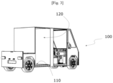
- FIG. 3 schematically illustrates a vehicle 100 of a system according to one embodiment of the invention which comprises a platform for receiving a container 10 with retractable wheels arranged opposite an access opening to the vehicle.
- This platform preferably extends at a distance less than 30 cm from the ground, preferably less than 20 cm from the ground to facilitate the loading and unloading operations described later.
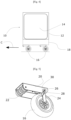
- FIG. 4 schematically illustrates a container 10 of a system according to the invention.
- This container 10 is intended to be loaded and unloaded from a vehicle 100 comprising a platform 110 which extends opposite an opening 120 for access to the vehicle.
- the particularity of the container 10 with retractable wheels of a system according to the invention and of a vehicle of a system according to the invention is that the loading and unloading of the container from the vehicle can be carried out by a single person without means of lifting. This loading and unloading can therefore be carried out anywhere and in particular near the recipients to be delivered.
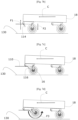
- the loading principle is described in connection with the figures 7a to 7f .
- the container comprises a box 12 comprising at least one opening 14 for access to the box to accommodate goods, not shown in the figures for the purposes of clarity.
- the container also includes rolling members 16 for moving the box in a preferred direction of advancement, and corresponding to the direction of the container when loading the container into a vehicle. This direction is represented by arrow C in the figures.
- the container also includes a box 18 for housing each rolling member arranged under the box 12.
- a single box 18 can house all of the rolling members 16.
- each rolling member can include its own box.
- the rolling members 16 are configured to be able to move from a position, called the deployed position, in which they extend outside the box 18 and thus allow the movement of the container 10 on a floor 130, and a position, called the retracted position, in which they are housed mainly in the box 18 when the container is in a vehicle.
- the particularity of the container of a system according to the invention is to obtain spontaneously by simple movement of the container towards the vehicle the tilting of the rolling members from the deployed position to the retracted position and vice versa.
- the rolling member 16 is mounted on a longitudinal frame 20 formed for example of a profile with a U-shaped transverse cross section and comprising at a first longitudinal end, three contact rollers 22 carried by the same mechanical shaft 23 which is extends on either side of the flanks of the profile forming the longitudinal reinforcement and at the opposite longitudinal end, a stirrup 24 for supporting the rolling member 16.
- This stirrup 24 comprises a first end which is mounted movable in rotation by relative to the armature 20 around a pivoting shaft 26 and an opposite end which forms a bearing of the rolling member 16.
- the base of the U-shaped profile of the longitudinal reinforcement is for example secured to the box 18 by bolting means or any equivalent means, not shown in the figures for purposes of clarity.
- the stirrup 24 also includes a locking tab 30 configured to fit into a mortise 32 formed in the lower part of the sides of the frame, directly above the locking tab when the rolling member is in the deployed position locked.
- the locking tab 30 is configured to be able to spontaneously separate by gravity from the mortise 32 when the rolling member passes from the retracted position to the free deployed position as illustrated in connection with the figures 7a to 7f .
- the locking tab 30 extends transversely on either side of the sides of said frame so as to form a longitudinal stop which hinders the swinging of the rolling member by contact with the frame during unloading of the container. As illustrated on the Figure 6 , the locking tab also includes a recess which allows the passage of the rolling member 16.
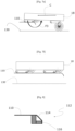
- This stop 112 is represented schematically in partial section by the figure 8 and comprises an inclined portion 114 which forms an elevation stop of the container and a vertical portion 116 extending towards the ground from the elevation stop and forming a tilting stop as explained below.
- a system and a method according to the invention are mainly intended to transport containers with retractable wheels from a peri-urban storage space to urban recipients.
- the system can also include, in addition to containers with retractable wheels, means of transporting pallets.
- containers with retractable wheels means of transporting pallets.
- the same urban electric vehicle cannot simultaneously transport a container with retractable wheels and the means of transporting pallets.
- the operator uses a container with retractable wheels or pallet transport means.
- pallet transport means include, for example, a roller plate carried by a set of wheels, the plate extending at the height of the platform of the urban electric vehicle.
- the pallets can be placed by an operator (manually or by means of a suitable pallet truck) on this roller plate, then the operator moves the set of wheels surmounted by the pallets to be loaded facing the opening of the vehicle and rolls the pallets on the roller plate into the interior of the vehicle.
Description
L'invention concerne un procédé et un système d'acheminement de colis à des destinataires urbains.The invention relates to a method and system for delivering packages to urban recipients.
Le volume de colis distribué augmente régulièrement du fait du développement du commerce à distance, plus communément désigné par l'expression de « e-commerce ». La logistique de distribution des colis, en particulier ceux issus du e-commerce, mais pas uniquement, est relativement complexe en particulier dans les centres villes des grandes métropoles.The volume of parcels distributed is regularly increasing due to the development of distance commerce, more commonly referred to as “e-commerce”. The logistics of parcel distribution, particularly those from e-commerce, but not only, is relatively complex, particularly in the city centers of large metropolises.
Pour faciliter l'acheminement des colis dans les centres urbains, il est aujourd'hui courant de scinder l'acheminement des colis entre leur lieu de collecte et leur lieu de distribution en plusieurs trajets parmi lesquels un trajet de collecte du colis entre le lieu de dépose du colis par l'expéditeur et un entrepôt de stockage initial, un trajet de transport entre l'entrepôt de stockage initial et l'entrepôt de stockage final (des trajets intermédiaires associés à des entrepôts de stockage intermédiaire peuvent être prévus selon les distances et les moyens de transport utilisés) et un trajet de livraison du colis entre l'entrepôt de stockage final, généralement localisé en zone péri-urbaine, et le destinataire du colis.To facilitate the delivery of parcels in urban centers, it is now common to split the delivery of parcels between their collection point and their distribution point into several journeys including a parcel collection route between the place of deposit of the package by the sender and an initial storage warehouse, a transport route between the initial storage warehouse and the final storage warehouse (intermediate journeys associated with intermediate storage warehouses may be planned depending on the distances and the means of transport used) and a delivery route for the package between the final storage warehouse, generally located in a peri-urban area, and the recipient of the package.
Chaque type de trajet (trajet de collecte, trajet de transport, trajet de distribution) nécessite le recours à des véhicules spécifiques.Each type of journey (collection route, transport route, distribution route) requires the use of specific vehicles.
A titre d'exemple, il est fréquent que le trajet de collecte mette en oeuvre des camionnettes permettant de récolter les colis sur les lieux de distribution (points relais, entreprises, etc.) associées éventuellement à des gros porteurs pour acheminer les colis vers un entrepôt de stockage de collecte. Le trajet de transport fait appel à des gros porteurs, à des véhicules ferroviaires ou aériens selon les destinations. Le trajet de distribution fait généralement appel à des véhicules plus légers, du type camionnettes thermiques, pour distribuer chaque colis à son point de distribution définitif.For example, it is common for the collection route to use vans to collect the packages from distribution points (relay points, businesses, etc.) possibly associated with large trucks to transport the packages to a collection storage warehouse. The transport route uses large aircraft, rail or air vehicles depending on the destinations. The distribution route generally uses lighter vehicles, such as thermal vans, to distribute each package to its point. final distribution.
Les études montrent que les trajets de distribution entre le lieu de stockage péri-urbain et les destinataires représentent en moyenne 20% du trafic, occupent 30% de la voirie et se trouvent à l'origine de 25% des émissions de gaz à effet de serre.Studies show that the distribution routes between the peri-urban storage location and the recipients represent on
Il est donc essentiel d'optimiser la chaine logistique de distribution des colis, en particulier en ce qui concerne les trajets au sein des zones urbaines, désignés aussi par la terminologie de trajets du dernier kilomètre.It is therefore essential to optimize the parcel distribution logistics chain, particularly with regard to journeys within urban areas, also referred to as last mile journeys.
Pour ce faire, il a déjà été proposé de mettre en place une nouvelle organisation qui vise la massification des flux entrants dans les zones urbaines et qui consiste à remplacer les camionnettes thermiques du trajet de distribution par un gros porteur pour assurer le trajet entre le centre de stockage périurbain et un centre de stockage urbain, couplé à une pluralité de camionnettes électriques pour assurer le dernier kilomètre entre le lieu de stockage urbain et les destinataires finaux. Cela permet de générer une économie de 20 à 30% par rapport aux solutions antérieures tout en limitant les émissions de gaz à effet de serre. En effet, le gros porteur présente une capacité de transport de l'ordre de huit camionnettes.To do this, it has already been proposed to set up a new organization which aims to massify incoming flows in urban areas and which consists of replacing the thermal vans on the distribution route with a large carrier to ensure the journey between the center peri-urban storage and an urban storage center, coupled with a plurality of electric vans to ensure the last mile between the urban storage location and the final recipients. This makes it possible to generate savings of 20 to 30% compared to previous solutions while limiting greenhouse gas emissions. In fact, the large carrier has a transport capacity of around eight vans.
Cette solution présente néanmoins l'inconvénient de générer une rupture de charge, c'est-à-dire de nécessiter le transfert des colis à la main entre le gros porteur et les véhicules urbains du dernier kilomètre au sein du centre de stockage urbain. Cette rupture de charge annule en grande partie les bénéfices liées à la massification des flux entrant dans les zones urbaines.This solution nevertheless has the disadvantage of generating a load break, that is to say of requiring the transfer of packages by hand between the large carrier and the last mile urban vehicles within the urban storage center. This break in load largely cancels out the benefits linked to the massification of flows entering urban areas.
Le déposant a notamment déjà décrit dans les documents XP55805994, XP55805995, XP55805998, XP55806002, XP55806003, XP55806010 et XP55806013 le problème technique qu'il cherche à résoudre et le principe général d'utiliser des véhicules urbains électriques associés à des containers à roues rétractables pour assurer le dernier kilomètre.The applicant has in particular already described in documents XP55805994, XP55805995, XP55805998, XP55806002, XP55806003, XP55806010 and XP55806013 the technical problem that he seeks to resolve and the general principle of using electric urban vehicles associated with containers with retractable wheels to ensure the last kilometer.
Le document
Le document
Les inventeurs ont donc cherché à proposer un procédé et un système de d'acheminement de colis à des destinataires urbains qui pallient au moins certains des inconvénients des solutions actuellement mises en oeuvre au sein des zones urbaines.The inventors have therefore sought to propose a method and a system for delivering parcels to urban recipients which overcome at least some of the disadvantages of the solutions currently implemented in urban areas.
L'invention vise à fournir un procédé et un système d'acheminement de colis à des destinataires urbains qui pallient au moins certains des inconvénients des solutions connues.The invention aims to provide a method and a system for delivering packages to urban recipients which overcome at least some of the disadvantages of known solutions.
L'invention vise en particulier à fournir, dans au moins un mode de réalisation de l'invention, un procédé et un système d'acheminement de colis à des destinataires urbains qui suppriment la rupture de charge au cours du dernier kilomètre et peut être mise en oeuvre par une personne seule.The invention aims in particular to provide, in at least one embodiment of the invention, a method and a system for delivering parcels to urban recipients which eliminates the break in load during the last kilometer and can be implemented implemented by a single person.
L'invention vise aussi à fournir, dans au moins un mode de réalisation de l'invention, un procédé et un système d'acheminement de colis à des destinataires urbains qui puissent être mis en oeuvre en dehors de tout entrepôt de stockage.The invention also aims to provide, in at least one embodiment of the invention, a method and a system for delivering packages to urban recipients which can be implemented outside of any storage warehouse.
L'invention vise aussi à fournir, dans au moins un mode de réalisation de l'invention, un procédé et un système d'acheminement de colis à des destinataires urbains qui ne nécessitent pas le recours à des chariots élévateurs.The invention also aims to provide, in at least one embodiment of the invention, a method and a system for delivering packages to urban recipients which do not require the use of forklifts.
L'invention vise aussi à fournir, dans au moins un mode de réalisation de l'invention, un procédé et un système d'acheminement de colis à des destinataires urbains qui n'imposent pas le recours à des véhicules équipés de hayons pour le dernier kilomètre.The invention also aims to provide, in at least one embodiment of the invention, a method and a system for delivering packages to recipients urban areas which do not require the use of vehicles equipped with tailgates for the last kilometer.
L'invention vise aussi à fournir, dans au moins un mode de réalisation de l'invention, un procédé et un système d'acheminement de colis à des destinataires urbains qui peuvent être adaptés à l'acheminement de produits en température dirigée, c'est-à-dire à température contrôlée et dépendante des colis transportés.The invention also aims to provide, in at least one embodiment of the invention, a method and a system for delivering packages to urban recipients which can be adapted to the delivery of temperature-controlled products, i.e. that is to say at a controlled temperature and dependent on the packages transported.
Pour ce faire, l'invention concerne un procédé d'acheminement d'une pluralité de colis à une pluralité de destinataires urbains à partir d'un espace de stockage périurbain comprenant les étapes consistant à :
- loger ladite pluralité de colis dans une pluralité de containers à roues rétractables, au moins un container à roues rétractables comprenant :
- o un caisson comprenant au moins une ouverture d'accès au caisson pour pouvoir y loger lesdits colis,
- ∘ des organes roulants de déplacement dudit caisson dans un sens d'avancement privilégié et selon une direction principale d'avancement, dite direction longitudinale,
- ∘ au moins un coffret de logement de chaque organe roulant agencé sous ledit caisson,
- ∘ chaque organe roulant étant monté mobile par rapport au caisson entre une position, dite position déployée, dans laquelle il s'étend hors dudit coffret et permet le déplacement par roulement dudit container hors d'un véhicule électrique urbain, et une position, dite position rétractée, dans laquelle il est logé principalement dans ledit coffret tout en permettant le déplacement par roulement dudit container sur ledit plancher bas dudit véhicule électrique urbain, ledit passage de ladite position déployée à ladite position rétractée étant obtenue spontanément lors du chargement du container dans ledit véhicule électrique urbain par la combinaison du déplacement dudit caisson selon la direction longitudinale et un contact entre le container et une butée transversale ménagée sous ledit plancher bas dudit véhicule électrique urbain, et le passage de ladite position rétractée à ladite position déployée étant obtenu spontanément par gravité lors du déchargement dudit container dudit véhicule électrique urbain,
- transporter ladite pluralité de containers à roues rétractables dans un véhicule roulant vers une base logistique urbaine,
- décharger lesdits containers à roues rétractables dans ladite base logistique urbaine,
- charger lesdits containers à roues rétractables dans une pluralité de véhicules électriques urbains à plancher bas et sans moyen de levage,
- déplacer lesdits véhicules électriques urbains chargés desdits containers de ladite base logistique urbaine vers lesdits destinataires urbains et décharger lesdits containers desdits véhicules électriques urbains sans moyen de levage à proximité desdits destinataires,
- livrer chaque colis logé dans chaque container à roues rétractables déchargé de chaque véhicule électrique urbain à chaque destinataire du colis.
- accommodate said plurality of packages in a plurality of containers with retractable wheels, at least one container with retractable wheels comprising:
- o a box comprising at least one access opening to the box to accommodate said packages,
- ∘ rolling members for moving said box in a preferred direction of advancement and in a main direction of advancement, called longitudinal direction,
- ∘ at least one housing box for each rolling member arranged under said box,
- ∘ each rolling member being mounted movable relative to the box between a position, called deployed position, in which it extends outside of said box and allows said container to be moved by rolling out of an urban electric vehicle, and a position, called position retracted, in which it is housed mainly in said box while allowing the rolling movement of said container on said low floor of said urban electric vehicle, said passage from said deployed position to said retracted position being obtained spontaneously when loading the container into said vehicle urban electric by the combination of the movement of said box according to the longitudinal direction and a contact between the container and a transverse stop provided under said low floor of said urban electric vehicle, and the passage from said retracted position to said deployed position being obtained spontaneously by gravity during the unloading of said container from said urban electric vehicle,
- transport said plurality of containers with retractable wheels in a rolling vehicle towards an urban logistics base,
- unload said containers with retractable wheels in said urban logistics base,
- loading said containers with retractable wheels into a plurality of low-floor urban electric vehicles without lifting means,
- move said urban electric vehicles loaded with said containers from said urban logistics base to said urban recipients and unload said containers from said urban electric vehicles without lifting means near said recipients,
- deliver each package housed in each retractable wheeled container unloaded from each urban electric vehicle to each recipient of the package.
Le procédé selon l'invention permet donc de supprimer la rupture de charge du dernier kilomètre en associant des containers à roues rétractables logeant les colis à acheminer et des véhicules électriques urbains à plancher bas configurés pour permettre de charger et décharger les containers sans moyen de levage.The method according to the invention therefore makes it possible to eliminate the last mile break in load by combining containers with retractable wheels housing the packages to be transported and low-floor urban electric vehicles configured to allow the containers to be loaded and unloaded without lifting means. .
Dans tout le texte, on désigne par plancher bas, un véhicule dont le plancher de réception des containers s'étend à moins de 30 cm du sol, de préférence moins de 20 cm du sol.Throughout the text, low floor means a vehicle whose container reception floor extends less than 30 cm from the ground, preferably less than 20 cm from the ground.
Le procédé selon l'invention permet en outre de massifier les flux entrants dans les zones urbaines en remplaçant les camionnettes thermiques du trajet de distribution des solutions connues par un gros porteur qui assure le trajet entre le centre de stockage périurbain et une base logistique urbaine, associé à des véhicules électriques configurés pour embarquer des containers à roues rétractables.The method according to the invention also makes it possible to consolidate incoming flows in urban areas by replacing the thermal vans in the distribution route of known solutions with a large carrier which ensures the journey between the peri-urban storage center and an urban logistics base, associated with electric vehicles configured to carry containers with retractable wheels.
L'originalité du procédé selon l'invention réside à la fois dans l'utilisation de véhicules électriques à plancher bas pour assurer le trajet du dernier kilomètre et dans l'utilisation de containers à roues rétractables compatibles avec ces véhicules électriques à plancher bas qui permettent un chargement et déchargement des containers sans moyen de levage.The originality of the method according to the invention lies both in the use of low-floor electric vehicles to ensure the last kilometer journey and in the use of containers with retractable wheels compatible with these low-floor electric vehicles which allow loading and unloading containers without lifting means.
Le procédé technique selon l'invention met en oeuvre des moyens techniques (containers à roues rétractables, véhicules urbains électriques à plancher bas, véhicules roulants) qui coopèrent les uns avec les autres pour fournir une solution technique au problème technique de la rupture de charge des procédés d'acheminement connus.The technical method according to the invention uses technical means (containers with retractable wheels, low-floor electric urban vehicles, rolling vehicles) which cooperate with each other to provide a technical solution to the technical problem of breaking the load of known delivery methods.
Selon l'invention, au moins un container à roues rétractables comprend :
- un caisson comprenant au moins une ouverture d'accès au caisson pour pouvoir y loger lesdits colis,
- des organes roulants de déplacement dudit caisson dans un sens d'avancement privilégié et selon une direction principale d'avancement, dite direction longitudinale,
- au moins un coffret de logement de chaque organe roulant agencé sous ledit caisson,
- chaque organe roulant étant monté mobile par rapport au caisson entre une position, dite position déployée, dans laquelle il s'étend hors dudit coffret et permet le déplacement par roulement dudit container hors dudit véhicule, et une position, dite position rétractée, dans laquelle il est logé principalement dans ledit coffret tout en permettant le déplacement par roulement dudit container sur ledit plancher bas dudit véhicule électrique urbain, ledit passage de ladite position déployée à ladite position rétractée étant obtenue spontanément lors du chargement du container dans ledit véhicule par la combinaison du déplacement dudit caisson selon la direction longitudinale et un contact entre le container et une butée transversale ménagée sous ledit plancher bas dudit véhicule électrique urbain, et le passage de ladite position rétractée à ladite position déployée étant obtenu spontanément par gravité lors du déchargement dudit container dudit véhicule.
- a box comprising at least one access opening to the box to accommodate said packages,
- rolling members for moving said box in a preferred direction of advancement and in a main direction of advancement, called longitudinal direction,
- at least one housing box for each rolling member arranged under said box,
- each rolling member being mounted movable relative to the box between a position, called deployed position, in which it extends outside of said box and allows the rolling movement of said container outside of said vehicle, and a position, called retracted position, in which it is housed mainly in said box while allowing the rolling movement of said container on said low floor of said urban electric vehicle, said passage from said deployed position to said retracted position being obtained spontaneously during loading of the container into said vehicle by the combination of movement of said box in the longitudinal direction and a contact between the container and a transverse stop provided under said low floor of said urban electric vehicle, and the passage from said retracted position to said deployed position being obtained spontaneously by gravity during the unloading of said container from said vehicle.
Selon cet aspect de l'invention, le container à roues rétractables présente la particularité de disposer d'organes roulants rétractables configurés pour basculer spontanément de leur position rétractée à leur position déployée et inversement par la combinaison du déplacement du container et d'une butée transversale agencée sous la plateforme du véhicule (pour le passage de la position déployée vers la position rétractée) et par la gravité (pour le passage de la position rétractée vers la position déployée).According to this aspect of the invention, the container with retractable wheels has the particularity of having retractable rolling members configured to switch spontaneously from their retracted position to their deployed position and vice versa by the combination of the movement of the container and a transverse stop arranged under the vehicle platform (for the passage from the deployed position to the retracted position) and by gravity (for the passage from the retracted position to the deployed position).
Ainsi, un opérateur peut charger et décharger le container d'un véhicule présentant une plateforme horizontale de réception de ce container et une butée transversale ménagée sous la plateforme, sans difficultés particulières, sans effort, et sans équipement spécifique. En particulier, le container permet de résoudre la problématique de la rupture de charge en supprimant le besoin de déplacer les colis d'un véhicule à un autre lors de la livraison du dernier kilomètre. Le container permet son utilisation à la fois pour le transport vers le dernier kilomètre, pour le transport du dernier kilomètre et pour son déplacement jusqu'au lieu de livraison final.Thus, an operator can load and unload the container from a vehicle having a horizontal platform for receiving this container and a transverse stop provided under the platform, without particular difficulties, without effort, and without specific equipment. In particular, the container helps solve the problem of load breakage by eliminating the need to move packages from one vehicle to another during last mile delivery. The container allows its use both for transport to the last mile, for transport of the last mile and for its movement to the final delivery location.
Avantageusement et selon l'invention, ladite étape qui consiste à livrer chaque colis du container transporté par chaque véhicule électrique urbain comprend en outre une étape de déplacement du container à roues rétractables par un bras amovible motorisé permettant de faciliter le déplacement du container dans les rues piétonnes et dans les entrepôts notamment. D'une manière générale, ce bras motorisé permet le déplacement d'un container à roues rétractables sur toute les surfaces (intérieures et/ou extérieures).Advantageously and according to the invention, said step which consists of delivering each package from the container transported by each urban electric vehicle further comprises a step of moving the container with retractable wheels by a motorized removable arm making it possible to facilitate the movement of the container in the streets pedestrians and in warehouses in particular. Generally speaking, this motorized arm allows the movement of a container with retractable wheels on all surfaces (interior and/or exterior).
Selon cet aspect de l'invention, le déplacement d'un container à roues rétractables, une fois déchargé d'un véhicule électrique, est facilité par l'utilisation d'un bras amovible motorisé configuré pour venir en prise sur le container. Cela permet notamment de faciliter le déplacement des containers dans les rues piétonnes et les entrepôts notamment sans nécessiter un effort substantiel de l'opérateur en charge de la préparation et de la livraison des colis.According to this aspect of the invention, the movement of a container with retractable wheels, once unloaded from an electric vehicle, is facilitated by the use of a motorized removable arm configured to engage the container. This makes it possible in particular to facilitate the movement of containers in pedestrian streets and warehouses, in particular without requiring a substantial effort of the operator in charge of the preparation and delivery of packages.
Selon une variante, les containers sont en outre équipés de moyens de liaison entre eux de telle sorte qu'un opérateur peut former une chaine de containers en les reliant entre eux et utiliser le bras amovible motorisé pour déplacer le premier container de la chaine de containers, ce qui entraine le déplacement de proche en proche de l'ensemble de la chaine de containers ainsi formée.According to a variant, the containers are also equipped with means of connection between them such that an operator can form a chain of containers by connecting them together and use the motorized removable arm to move the first container of the chain of containers , which causes the entire chain of containers thus formed to be moved step by step.
L'invention concerne aussi un système d'acheminement d'une pluralité de colis à une pluralité de destinataires urbains à partir d'un espace de stockage périurbain comprenant :
- une pluralité de containers à roues rétractables configurés pour pouvoir y loger ladite pluralité de colis à acheminer,
- un véhicule roulant adapté pour y loger ladite pluralité de containers à roues rétractables et destiné à les déplacer vers une base logistique urbaine,
- une pluralité de véhicules électriques urbains à plancher bas adaptés pour recevoir chacun au moins un container à roues rétractables et destinés à livrer chaque colis à leur destinataire.
- a plurality of containers with retractable wheels configured to accommodate said plurality of packages to be transported,
- a rolling vehicle adapted to accommodate said plurality of containers with retractable wheels and intended to move them towards an urban logistics base,
- a plurality of low-floor urban electric vehicles adapted to each receive at least one container with retractable wheels and intended to deliver each package to their recipient.
Selon l'invention, au moins un container à roues rétractables comprend :
- un caisson comprenant au moins une ouverture d'accès au caisson pour pouvoir y loger lesdits colis,
- des organes roulants de déplacement dudit caisson dans un sens d'avancement privilégié et selon une direction principale d'avancement, dite direction longitudinale,
- au moins un coffret de logement de chaque organe roulant agencé sous ledit caisson,
- chaque organe roulant étant monté mobile par rapport au caisson entre une position, dite position déployée, dans laquelle il s'étend hors dudit coffret et permet le déplacement par roulement dudit container hors dudit véhicule, et une position, dite position rétractée, dans laquelle il est logé principalement dans ledit coffret tout en permettant le déplacement par roulement dudit container sur ledit plancher bas dudit véhicule électrique urbain, ledit passage de ladite position déployée à ladite position rétractée étant obtenue spontanément lors du chargement du container dans ledit véhicule par la combinaison du déplacement dudit caisson selon la direction longitudinale et un contact entre le container et une butée transversale ménagée sous ledit plancher bas dudit véhicule électrique urbain, et le passage de ladite position rétractée à ladite position déployée étant obtenu spontanément par gravité lors du déchargement dudit container dudit véhicule.
- a box comprising at least one access opening to the box to accommodate said packages,
- rolling members for moving said box in a preferred direction of advancement and in a main direction of advancement, called longitudinal direction,
- at least one housing box for each rolling member arranged under said box,
- each rolling member being mounted movable relative to the box between a position, called deployed position, in which it extends outside of said box and allows the rolling movement of said container outside of said vehicle, and a position, called retracted position, in which it is housed mainly in said box while allowing the rolling movement of said container on said low floor of said urban electric vehicle, said passage from said deployed position to said retracted position being obtained spontaneously during loading of the container into said vehicle by the combination of the movement of said box in the longitudinal direction and a contact between the container and a transverse stop provided under said low floor of said urban electric vehicle, and the passage from said retracted position to said deployed position being obtained spontaneously by gravity during the unloading of said container of said vehicle.
Les avantages et effets techniques d'un procédé selon l'invention s'appliquent mutatis mutandis à un système selon l'invention.The advantages and technical effects of a process according to the invention apply mutatis mutandis to a system according to the invention.
Un système selon l'invention met avantageusement en oeuvre un procédé selon l'invention et le procédé selon l'invention est avantageusement mis en oeuvre par un système selon l'invention.A system according to the invention advantageously implements a method according to the invention and the method according to the invention is advantageously implemented by a system according to the invention.
Avantageusement et selon l'invention, chaque véhicule électrique urbain est en outre équipé d'un bras amovible motorisé permettant de faciliter le déplacement du container dans des rues piétonnes ou les entrepôts notamment, et d'une manière générale sur toutes les surfaces intérieures et/ou extérieures.Advantageously and according to the invention, each urban electric vehicle is further equipped with a motorized removable arm making it possible to facilitate the movement of the container in pedestrian streets or warehouses in particular, and in general on all interior surfaces and/or or exterior.
Avantageusement, un container à roues rétractables d'un système selon l'invention comprend en outre, pour chaque organe roulant, une armature longitudinale comprenant à une première extrémité longitudinale, au moins une roulette de contact avec ladite butée transversale, et à une seconde extrémité longitudinale, un étrier de support dudit organe roulant monté mobile en rotation par rapport à ladite armature autour d'un axe transversal, dit axe de pivotement, permettant audit organe roulant de passer de ladite position déployée à ladite position rétractée lors du chargement du container dans ledit véhicule et inversement lors du déchargement dudit container hors dudit véhicule, chaque roulette de contact formant en outre des moyens de roulement additionnels dudit container sur ladite plateforme horizontale dudit véhicule lorsque lesdits organes roulants sont dans ladite position rétractée.Advantageously, a container with retractable wheels of a system according to the invention further comprises, for each rolling member, a longitudinal frame comprising at a first longitudinal end, at least one contact wheel with said transverse stop, and at a second end longitudinal, a support bracket for said rolling member mounted movable in rotation relative to said frame around a transverse axis, called pivot axis, allowing said rolling member to pass from said deployed position to said retracted position when loading the container into said vehicle and conversely when unloading said container from said vehicle, each contact roller further forming additional means for rolling said container on said horizontal platform of said vehicle when said rolling members are in said retracted position.
Selon cet aspect avantageux de l'invention, chaque organe roulant est porté par une armature longitudinale équipée de roulettes de contact configurées pour faciliter le chargement du container dans le véhicule. En outre, ces roulettes participent au déplacement par roulement du container sur la plateforme du véhicule lorsque le container est logé dans le véhicule.According to this advantageous aspect of the invention, each rolling member is carried by a longitudinal frame equipped with contact rollers configured to facilitate loading of the container into the vehicle. In addition, these casters participate in the rolling movement of the container on the vehicle platform when the container is housed in the vehicle.
Chaque organe roulant est en outre monté sur un étrier pivotant par rapport à ladite armature entre la position rétractée et la position déployée et inversement.Each rolling member is further mounted on a stirrup pivoting relative to said frame between the retracted position and the deployed position and vice versa.
Avantageusement et selon l'invention, chaque étrier de support dudit organe roulant d'un container comprend :
- un arbre formant l'axe de pivotement s'étendant dans une lumière oblongue verticale ménagée dans ladite armature et configuré pour pouvoir se déplacer spontanément par gravité dans ladite lumière oblongue d'une position, dite position verrouillée, à une position, dite position libre, et inversement par contact dudit organe roulant avec le sol,
- une patte de verrouillage configurée pour venir s'encastrer dans une mortaise formée dans ladite armature longitudinale dans ladite position verrouillée et pour pouvoir s'en désolidariser spontanément sous l'effet de la gravité lors du passage vers ladite position libre.
- a shaft forming the pivot axis extending in a vertical oblong slot provided in said frame and configured to be able to move spontaneously by gravity in said oblong slot from a position, called locked position, to a position, called free position, and vice versa by contact of said rolling member with the ground,
- a locking tab configured to fit into a mortise formed in said longitudinal frame in said locked position and to be able to separate spontaneously under the effect of gravity when moving to said free position.
Selon cet aspect de l'invention, chaque organe roulant peut présenter trois positions distinctes : une position déployée verrouillée dans laquelle l'organe roulant est sorti du coffret de logement et la patte de verrouillage associée est encastrée dans la mortaise conjuguée formée dans l'armature longitudinale ; une position déployée libre dans laquelle l'organe roulant est sorti du coffret de logement et la patte de verrouillage associée est désolidarisée de la mortaise conjuguée sous l'effet de la gravité (l'organe roulant ne touchant pas le sol dans cette position du fait du déplacement de l'arbre de pivotement dans la lumière oblongue verticale) ; une position rétractée dans laquelle l'organe roulant est pivoté par rapport à la position déployée et est logé dans le coffret de logement.According to this aspect of the invention, each rolling member can have three distinct positions: a locked deployed position in which the rolling member is taken out of the housing box and the associated locking tab is embedded in the conjugate mortise formed in the frame longitudinal; a free deployed position in which the rolling member has come out of the housing box and the associated locking tab is separated from the combined mortise under the effect of gravity (the rolling member not touching the ground in this position due to the movement of the pivot shaft in the vertical oblong slot); a retracted position in which the rolling member is pivoted relative to the deployed position and is housed in the housing box.
Avantageusement et selon l'invention, au moins un véhicule électrique urbain comprend une plateforme de réception dudit container agencée en regard d'une ouverture d'accès au véhicule, ladite plateforme s'étendant à une distance inférieure à 30 cm sol, de préférence inférieure à 20 cm du sol, et supérieure à la distance qui sépare, dans la dite position déployée desdits organes roulants, l'axe de pivotement et la surface de contact desdits organes roulants avec le sol, et ladite plateforme comprenant une butée transversale ménagée sous la plateforme dudit véhicule qui présente une portion inclinée formant une butée d'élévation dudit container par contact avec desdites roulettes de contact dudit container et permettant de passer lesdits organes roulants de ladite position verrouillée à ladite position libre, et une portion verticale s'étendant vers le sol depuis ladite butée d'élévation formant une butée de basculement dudit organe roulant de ladite position déployée libre à ladite position rétractée.Advantageously and according to the invention, at least one urban electric vehicle comprises a platform for receiving said container arranged opposite an access opening to the vehicle, said platform extending at a distance less than 30 cm from the ground, preferably less 20 cm from the ground, and greater than the distance which separates, in said deployed position of said rolling members, the pivot axis and the contact surface of said rolling members with the ground, and said platform comprising a transverse stop provided under the platform of said vehicle which has an inclined portion forming an elevation stop of said container by contact with said contact rollers of said container and allowing said rolling members to pass from said locked position to said free position, and a vertical portion extending towards the ground from said elevation stop forming a tilting stop of said rolling member from said free deployed position to said retracted position.
Ainsi et selon cet aspect de l'invention, lors du déplacement du container vers un véhicule selon l'invention selon la direction longitudinale, les roulettes de contact entre en contact avec la butée d'élévation, ce qui permet de soulever légèrement le container du sol, et entraine spontanément le passage de l'organe roulant de la position déployée verrouillée à la position déployée libre, par la désolidarisation entre la patte de verrouillage et la mortaise associée qui résulte du coulissement de l'arbre de pivotement dans la lumière de guidage verticale. La poursuite du déplacement le long de la direction longitudinale entraine le contact entre l'organe roulant et la butée de basculement, ce qui entraine spontanément le passage de l'organe roulant de la position déployée libre à la position rétractée par pivotement de l'arbre de pivotement.Thus and according to this aspect of the invention, when moving the container towards a vehicle according to the invention in the longitudinal direction, the contact rollers come into contact with the elevation stop, which makes it possible to slightly lift the container from the ground, and spontaneously causes the rolling member to pass from the locked deployed position to the free deployed position, by the separation between the locking tab and the associated mortise which results from the sliding of the pivot shaft in the guide slot vertical. The continuation of the movement along the longitudinal direction causes contact between the rolling member and the tilting stop, which spontaneously causes the rolling member to pass from the freely deployed position to the retracted position by pivoting of the shaft pivoting.
De préférence, la plateforme est fixe, horizontale et s'étend dans un plan sensiblement parallèle au sol sur lequel repose le véhicule selon l'invention. Cela étant, selon d'autres variantes, la plateforme peut présenter une légère inclinaison par rapport à l'horizontale, par exemple un angle de 10° par rapport à l'horizontale. Selon ce mode de réalisation spécifique, la plateforme peut être montée sur des moyens élastiques, tels que des ressorts, configurés pour maintenir la plateforme selon cet angle de 10°, en l'absence du container, et être comprimés par le container, lorsque ce dernier est chargé sur la plateforme, de telle sorte qu'elle se positionne à l'horizontale. Un des avantages de ce mode réalisation spécifique est de permettre aux ressorts d'exercer une force d'élévation du container vers le plafond du véhicule, ce qui a pour effet de coincer le container entre la plateforme et le plafond et d'éviter tout déplacement du container à l'intérieur du véhicule.Preferably, the platform is fixed, horizontal and extends in a plane substantially parallel to the ground on which the vehicle according to the invention rests. However, according to other variants, the platform may have a slight inclination relative to the horizontal, for example an angle of 10° relative to the horizontal. According to this specific embodiment, the platform can be mounted on elastic means, such as springs, configured to maintain the platform at this angle of 10°, in the absence of the container, and be compressed by the container, when this The latter is loaded onto the platform, so that it is positioned horizontally. One of the advantages of this specific embodiment is to allow the springs to exert a lifting force on the container towards the ceiling of the vehicle, which has the effect of trapping the container between the platform and the ceiling and avoiding any movement. from the container inside the vehicle.
L'invention concerne également un procédé et un système d'acheminement de colis à des destinataires urbains caractérisés en combinaison par tout ou partie des caractéristiques mentionnées ci-dessus ou ci-après.The invention also relates to a method and a system for delivering packages to urban recipients characterized in combination by all or part of the characteristics mentioned above or below.
D'autres buts, caractéristiques et avantages de l'invention apparaîtront à la lecture de la description suivante donnée à titre uniquement non limitatif et qui se réfère aux figures annexées dans lesquelles :
- [
Fig. 1 ] est une vue schématique d'un procédé selon l'invention, - [
Fig. 2 ] est une autre représentation du procédé de lafigure 1 , - [
Fig. 3 ] est une vue schématique en perspective d'un véhicule à plancher bas d'un système selon un mode de réalisation de l'invention, - [
Fig. 4 ] est une vue schématique de côté d'un container à roues rétractables d'un système selon un mode de réalisation de l'invention, - [
Fig. 5 ] est une vue schématique en perspective de dessous d'un organe roulant d'un container d'un système selon un mode de réalisation de l'invention, - [
Fig. 6 ] est une vue schématique en perspective de dessous-avant de l'organe roulant de lafigure 5 , - [
Fig. 7a ] est une vue schématique de côté du container d'un système selon un mode de réalisation de l'invention en phase de chargement dans un véhicule, l'organe roulant avant représenté étant dans la position déployée verrouillée, - [
Fig. 7b ] est une vue schématique de côté du container selon un mode de réalisation de l'invention en phase de chargement dans un véhicule, l'organe roulant avant représenté basculant dans la position déployée libre, - [
Fig. 7c ] est une vue schématique de côté du container selon un mode de réalisation de l'invention en phase de chargement dans un véhicule, l'organe roulant avant représenté étant dans la position déployée libre, - [
Fig. 7d ] est une vue schématique de côté du container selon un mode de réalisation de l'invention en phase de chargement dans un véhicule, l'organe roulant avant représenté basculant dans la position rétractée, - [
Fig. 7e ] est une vue schématique de côté du container selon un mode de réalisation de l'invention en phase de chargement dans un véhicule, l'organe roulant avant représenté étant dans la position rétractée, - [
Fig. 7f ] est une vue schématique de côté du container selon un mode de réalisation de l'invention chargé dans un véhicule, les organes roulants avant et arrière représentés étant chacun dans la position rétractée, - [
Fig. 8 ] est une vue schématique en coupe d'une plateforme horizontale d'un véhicule d'un système selon un mode de réalisation de l'invention.
- [
Fig. 1 ] is a schematic view of a process according to the invention, - [
Fig. 2 ] is another representation of the process offigure 1 , - [
Fig. 3 ] is a schematic perspective view of a low-floor vehicle of a system according to one embodiment of the invention, - [
Fig. 4 ] is a schematic side view of a container with retractable wheels of a system according to one embodiment of the invention, - [
Fig. 5 ] is a schematic perspective view from below of a rolling member of a container of a system according to one embodiment of the invention, - [
Fig. 6 ] is a schematic bottom-front perspective view of the rolling member of theFigure 5 , - [
Fig. 7a ] is a schematic side view of the container of a system according to one embodiment of the invention in the loading phase in a vehicle, the front rolling member shown being in the locked deployed position, - [
Fig. 7b ] is a schematic side view of the container according to a mode of embodiment of the invention in the loading phase in a vehicle, the front rolling member shown tilting into the free deployed position, - [
Fig. 7c ] is a schematic side view of the container according to one embodiment of the invention in the loading phase in a vehicle, the front rolling member shown being in the free deployed position, - [
Fig. 7d ] is a schematic side view of the container according to one embodiment of the invention in the loading phase in a vehicle, the front rolling member shown tilting into the retracted position, - [
Fig. 7th ] is a schematic side view of the container according to one embodiment of the invention in the loading phase in a vehicle, the front rolling member shown being in the retracted position, - [
Fig. 7f ] is a schematic side view of the container according to one embodiment of the invention loaded in a vehicle, the front and rear rolling members shown each being in the retracted position, - [
Fig. 8 ] is a schematic sectional view of a horizontal platform of a vehicle of a system according to one embodiment of the invention.
Sur les figures, les échelles et les proportions ne sont pas strictement respectées et ce, à des fins d'illustration et de clarté.In the figures, scales and proportions are not strictly respected for purposes of illustration and clarity.
En outre, les éléments identiques, similaires ou analogues sont désignés par les mêmes références dans toutes les figures.In addition, identical, similar or analogous elements are designated by the same references in all the figures.
La
Le procédé comprend une première étape E1 qui consiste à loger ladite pluralité de colis dans une pluralité de containers 10 à roues rétractables. Cette étape n'est pas représentée sur la
Le procédé comprend une deuxième étape E2 qui consiste à transporter ladite pluralité de containers à roues rétractables 10 dans un véhicule roulant 60 vers des bases logistiques urbaines 70. Selon cet aspect de l'invention, un véhicule unique transporte ladite pluralité de containers 10 depuis un entrepôt de stockage périurbain jusqu'à une ou plusieurs bases logistiques urbaines 70. Sur la
Le procédé comprend une troisième étape E3 qui consiste à décharger lesdits containers à roues rétractables 10 dans chaque base logistique urbaine 70. Cette étape n'est pas représentée sur la
Le procédé comprend une quatrième étape E4 qui consiste à charger lesdits containers 10 à roues rétractables dans une pluralité de véhicules 100 électriques urbains à plancher bas. Une base logistique urbaine 70 peut comprendre un ou plusieurs véhicules électriques urbains selon le volume de containers à roues rétractables qu'il reçoit.The method comprises a fourth step E4 which consists of loading said
Le procédé comprend une cinquième étape E5 qui consiste à déplacer chaque véhicule électrique urbain à proximité des destinataires des colis et à décharger du véhicule le container sans moyen de levage.The method includes a fifth step E5 which consists of moving each urban electric vehicle near the recipients of the packages and unloading the container from the vehicle without lifting means.
Enfin, le procédé comprend une dernière étape E6 qui consiste à livrer chaque colis logé dans chaque container 10 à roues rétractables à chaque destinataire du colis.Finally, the method includes a final step E6 which consists of delivering each package housed in each
La
La
Le container comprend un caisson 12 comprenant au moins une ouverture 14 d'accès au caisson pour pouvoir y loger des marchandises, non représentées sur les figures à des fins de clarté.The container comprises a
Le container comprend également des organes roulants 16 de déplacement du caisson dans un sens d'avancement privilégié, et correspondant à la direction du container lors du chargement du container dans un véhicule. Cette direction est représentée par la flèche C sur les figures.The container also includes rolling
Le container comprend également un coffret 18 de logement de chaque organe roulant agencé sous le caisson 12. Dans le mode de réalisation des figures, un seul coffret 18 peut loger l'ensemble des organes roulants 16. Selon d'autres modes de réalisation, chaque organe roulant peut comprendre son propre coffret.The container also includes a
Les organes roulants 16 sont configurés pour pouvoir se déplacer d'une position, dite position déployée, dans laquelle ils s'étendent hors du coffret 18 et permettent ainsi le déplacement du container 10 sur un sol 130, et une position, dite position rétractée, dans laquelle ils sont logés principalement dans le coffret 18 lorsque le container est dans un véhicule. La particularité du container d'un système selon l'invention est d'obtenir spontanément par simple déplacement du container vers le véhicule le basculement des organes roulant de la position déployée à la position rétractée et inversement.The rolling
Sur les
Les
L'organe roulant 16 est monté sur une armature longitudinale 20 formée par exemple d'un profilé à section droite transversale en forme de U et comprenant à une première extrémité longitudinale, trois roulettes 22 de contact portées par un même arbre mécanique 23 qui s'étend de part et d'autre des flancs du profilé formant l'armature longitudinale et à l'extrémité longitudinale opposée, un étrier 24 de support de l'organe roulant 16. Cet étrier 24 comprend une première extrémité qui est montée mobile en rotation par rapport à l'armature 20 autour d'un arbre de pivotement 26 et une extrémité opposée qui forme un pallier de l'organe roulant 16.The rolling
La base du profilé en forme de U de l'armature longitudinale est par exemple solidarisée au coffret 18 par des moyens de boulonnerie ou tous moyens équivalents, non représentés sur les figures à des fins de clarté.The base of the U-shaped profile of the longitudinal reinforcement is for example secured to the
On observe sur la
L'étrier 24 comprend également une patte de verrouillage 30 configurée pour venir s'encastrer dans une mortaise 32 formée dans la partie inférieure des flancs de l'armature, à l'aplomb de la patte de verrouillage lorsque l'organe roulant est dans la position déployée verrouillée.The
La patte de verrouillage 30 est configurée pour pouvoir se désolidariser spontanément par gravité de la mortaise 32 lors du passage de l'organe roulant de la position rétractée à la position déployée libre comme illustré en lien avec les
La patte de verrouillage 30 s'étend transversalement de part et d'autre des flancs de ladite armature de manière à former une butée longitudinale qui entrave le balancement de l'organe roulant par contact avec l'armature lors du déchargement du container. Comme illustré sur la
Le principe de chargement du container dans un véhicule va maintenant être expliqué en lien avec les
Sur ces figures, seuls les organes roulants et le coffret 18 sont représentés à des fins de clarté. En outre, le véhicule de chargement n'est pas représenté à l'exception de la plateforme horizontale 110 et d'une butée transversale 112 qui s'étend transversalement sous la plateforme horizontale au niveau de la porte d'accès au véhicule.In these figures, only the rolling members and the
Un opérateur déplace le container jusqu'à atteindre la position représentée sur la
Cette butée 112 est représentée schématiquement en coupe partielle par la
A partir de la position de la
A partir de la position de la
A partir de la position de la
Une fois que la première paire d'organes roulant 16 est logée dans le coffret, si l'opérateur poursuit son déplacement du container selon la direction représentée par la flèche C vers l'intérieur du véhicule, les organes roulants arrière vont suivre le même principe pour basculer de la position déployée à la position rétractée.Once the first pair of rolling
La
Lors du déchargement du container du véhicule, les opérations inverses sont rencontrées de telle sorte qu'un opérateur puisse simplement décharger le container sans moyen de levage et sans assistance particulière.When unloading the container from the vehicle, reverse operations are encountered so that an operator can simply unload the container without lifting means and without special assistance.
Un système et un procédé selon l'invention sont principalement destinés à transporter des containers à roues rétractables d'un espace de stockage périurbain à des destinataires urbains.A system and a method according to the invention are mainly intended to transport containers with retractable wheels from a peri-urban storage space to urban recipients.
Cela étant et selon une variante de l'invention, le système peut également comprendre, en plus des containers à roues rétractables, des moyens de transport de palettes. Bien évidemment, un même véhicule électrique urbain ne peut simultanément transporter un container à roues rétractables et les moyens de transport des palettes. Selon le besoin, l'opérateur utilise un container à roues rétractables ou les moyens de transport des palettes. Ces moyens de transport des palettes comprennent par exemple une platine à rouleaux portée par un train de roues, la platine s'étendant à hauteur de la plateforme du véhicule électrique urbain.This being said and according to a variant of the invention, the system can also include, in addition to containers with retractable wheels, means of transporting pallets. Obviously, the same urban electric vehicle cannot simultaneously transport a container with retractable wheels and the means of transporting pallets. Depending on the need, the operator uses a container with retractable wheels or pallet transport means. These pallet transport means include, for example, a roller plate carried by a set of wheels, the plate extending at the height of the platform of the urban electric vehicle.
Ainsi, les palettes peuvent être déposées par un opérateur (manuellement ou au moyen d'une transpalette adaptée) sur cette platine à rouleaux, puis l'opérateur déplace le train de roues surmonté des palettes à charger en regard de l'ouverture du véhicule et fait rouler les palettes sur la platine à rouleaux jusqu'à l'intérieur du véhicule.Thus, the pallets can be placed by an operator (manually or by means of a suitable pallet truck) on this roller plate, then the operator moves the set of wheels surmounted by the pallets to be loaded facing the opening of the vehicle and rolls the pallets on the roller plate into the interior of the vehicle.
Claims (7)
- Method for delivering a plurality of parcels to a plurality of urban recipients (200) from a peri-urban storage space, characterized in that it comprises the steps consisting of :- housing (E1) said plurality of packages in a plurality of shrink-wheel containers, at least one container with retractable wheels container comprising :∘ a casing (12) comprising at least one access opening to the casing to accommodate said parcels,∘ rolling elements (16) for moving said box in a preferred direction of advance and along a main direction of advance, known as the longitudinal direction,∘ at least one housing for each rolling element, located beneath said casing,∘ each rolling member (16) being mounted so as to be movable relative to the casing between a position, referred to as the deployed position, in which it extends out of said casing and enables rolling displacement of said container out of an urban electric vehicle, and a position, referred to as the retracted position, in which it is housed mainly in said casing while enabling rolling displacement of said container on said low floor of said urban electric vehicle, said passage from said deployed position to said retracted position being obtained spontaneously during loading of the container into said urban electric vehicle by the combination of displacement of said casing in the longitudinal direction and contact between the container and a transverse stop provided under said low floor of said urban electric vehicle, and passage from said retracted position to said deployed position being obtained spontaneously by gravity during unloading of said container from said urban electric vehicle,- transporting (E2) said plurality containers with retractable wheels in a wheeled vehicle to an urban logistics base,- unloading (E3) said containers with retractable wheels into said urban logistics base,- loading (E4) said containers with retractable wheels into a plurality of low-floor urban electric vehicles without lifting means,- move (E5) said urban electric vehicles loaded with said containers from said urban logistics base to said urban consignees and unload said containers from said urban electric vehicles without lifting means in the vicinity of said consignees,- delivering (E6) each parcel housed in each container with retractable wheels unloaded from each urban electric vehicle to each parcel recipient.
- A delivery method according to claim 1, characterized in that said step which consists in delivering (E6) each parcel of the container transported by each urban electric vehicle further comprises a step of moving the container with retractable wheels by a motorized removable arm enabling the container to be moved more easily in pedestrian streets or warehouses in the vicinity of said addressees.
- A system for delivering a plurality of parcels to a plurality of urban recipients from a peri-urban storage area comprising :- a plurality of containers (10) with retractable wheels configured to accommodate said plurality of parcels to be conveyed,- at least one wheeled vehicle (20) adapted to house said plurality of retractable-wheel containers (10) and to move them to an urban logistics base,- a plurality of low-floor urban electric vehicles (100) each adapted to receive at least one container with retractable wheels (10) and intended to deliver each parcel to each recipient, said vehicles and said containers being configured to allow loading and unloading of each container with retractable wheels in each vehicle without lifting means,characterized in that at least one container with retractable wheels comprises :- a casing (12) comprising at least one access opening to the casing to accommodate said packages,- rolling elements (16) for moving said box in a preferred direction of advance and along a main direction of advance, known as the longitudinal direction,- at least one housing box for each rolling element, located beneath said csing,- each rolling member (16) being mounted so as to be movable relative to the casing between a position, referred to as the deployed position, in which it extends out of said casing and enables rolling displacement of said container out of said urban electric vehicle, and a position, referred to as the retracted position, in which it is housed mainly in said casing while enabling rolling displacement of said container on said low floor of said urban electric vehicle, said passage from said deployed position to said retracted position being obtained spontaneously during loading of the container into said urban electric vehicle by the combination of displacement of said box in the longitudinal direction and contact between the container and a transverse stop provided under said low floor of said urban electric vehicle, and passage from said retracted position to said deployed position being obtained spontaneously by gravity during unloading of said container from said urban electric vehicle.
- System according to claim 3, characterized in that it further comprises, for each rolling member (16), a longitudinal frame (20) comprising, at a first longitudinal end, at least one roller (22) for contact with said transverse stop (112), and at a second longitudinal end, a bracket (24) for supporting said rolling member (16) mounted so as to be able to rotate with respect to said frame (20) about a transverse axis, known as the pivot axis, enabling said rolling member (16) to move from said deployed position to said retracted position when loading the container (10) into said vehicle and vice versa when unloading said container (10) from said vehicle, each contact roller (22) further forming additional rolling means for said container (10) on said horizontal platform of said vehicle when said rolling members (16) are in said retracted position.
- System according to claim 4, characterized in that each bracket (20) for supporting said rolling member (16) comprises :- a shaft (26) forming the pivot axis, extending into a vertical oblong slot (28) formed in said frame (20) and configured to be able to move spontaneously by gravity in said oblong slot (28) from a position, called the locked position, to a position, called the free position, and vice versa by contact of said rolling member (16) with the ground (130),- a locking lug (30) configured to engage in a mortise (32) formed in said longitudinal frame (20) in said locked position and to disengage spontaneously under the effect of gravity when moving to said free position.
- System according to one of claims 3 to 5, characterized in that at least one urban electric vehicle (100) comprises a platform (110) for receiving said container arranged opposite an access opening (120) to the vehicle, characterized in that said platform (110) extends at a distance of less than 30 cm from the ground, preferably less than 20 cm from the ground, and greater than the distance which separates, in said deployed position of said rolling members (16), the pivot axis and the contact surface of said rolling members with the ground, and in that said platform (110) comprises a transverse stop (112) provided under the platform of said vehicle which has an inclined portion forming an elevation stop (114) for said container by contact with said contact wheels of said container and enabling said rolling members to be moved from said locked position to said free position, and a vertical portion extending towards the ground from said elevation stop forming a tilting stop (116) for said rolling member from said deployed free position to said retracted position.
- System according to one of claims 3 to 6, characterized in that each urban electric vehicle (100) is further equipped with a motorized removable arm to facilitate movement of the container in pedestrian streets or warehouses.
Priority Applications (1)
| Application Number | Priority Date | Filing Date | Title |
|---|---|---|---|
| EP21153570.3A EP4033429B1 (en) | 2021-01-26 | 2021-01-26 | Method and system for delivering parcels to urban recipients |
Applications Claiming Priority (1)
| Application Number | Priority Date | Filing Date | Title |
|---|---|---|---|
| EP21153570.3A EP4033429B1 (en) | 2021-01-26 | 2021-01-26 | Method and system for delivering parcels to urban recipients |
Publications (3)
| Publication Number | Publication Date |
|---|---|
| EP4033429A1 EP4033429A1 (en) | 2022-07-27 |
| EP4033429C0 EP4033429C0 (en) | 2023-11-15 |
| EP4033429B1 true EP4033429B1 (en) | 2023-11-15 |
Family
ID=74285302
Family Applications (1)
| Application Number | Title | Priority Date | Filing Date |
|---|---|---|---|
| EP21153570.3A Active EP4033429B1 (en) | 2021-01-26 | 2021-01-26 | Method and system for delivering parcels to urban recipients |
Country Status (1)
| Country | Link |
|---|---|
| EP (1) | EP4033429B1 (en) |
Family Cites Families (2)
| Publication number | Priority date | Publication date | Assignee | Title |
|---|---|---|---|---|
| ITPN20030061A1 (en) * | 2003-09-19 | 2005-03-20 | Ciro Corvino | MULTIFUNCTIONAL TROLLEY. |
| US20080303248A1 (en) * | 2007-06-10 | 2008-12-11 | Omar Chaparro | Portable shopping cart port-a-cart |
-
2021
- 2021-01-26 EP EP21153570.3A patent/EP4033429B1/en active Active
Also Published As
| Publication number | Publication date |
|---|---|
| EP4033429A1 (en) | 2022-07-27 |
| EP4033429C0 (en) | 2023-11-15 |
Similar Documents
| Publication | Publication Date | Title |
|---|---|---|
| CA2170385A1 (en) | Automatic mechanized system for the storage of objects | |
| FR2965257A1 (en) | System for handling road trailer to load trailer in transport unit e.g. hold of ship, has cradle associated with axle stand designed to support axles of trailer, where cradle is designed to support front part of trailer | |
| EP1792829B1 (en) | Method, system and devices for transporting containers | |
| WO2022058569A1 (en) | Order picking or buffer storage system | |
| EP4033429B1 (en) | Method and system for delivering parcels to urban recipients | |
| FR3038308A1 (en) | STORAGE AND TRANSFER DEVICE | |
| EP3421717B1 (en) | Follower gear of a tunnelling machine comprising means for conveying a keystone | |
| EP3219541B1 (en) | Set of two vehicles for distributing objects | |
| FR3037935A1 (en) | INCLINABLE TRAY TRUCK FOR A GROUND CONVEYING APPARATUS | |
| EP2252493A2 (en) | Car for handling heavy loads, particular a railway one, and use of said car in the presence of a catenary system | |
| EP4032747A1 (en) | Mobile container for transporting goods and vehicle equipped with such a container | |
| FR2944488A1 (en) | Autonomous loading bed for e.g. trailer, has pushing units pushing raising wall between loading position in which lower edge rests on bottom and unloading position in which lower edge is remote from bottom, and raises and pushes back load | |
| FR2919239A1 (en) | Luggage container transferring vehicle for use with aircraft, has traction engine removably hooked on trailer for simultaneously towing trailer and ensuring transfer of containers through transfer platform | |
| EP3013639B1 (en) | Facility for loading and unloading containers | |
| EP1827904B1 (en) | Mobile support and transfer cross-member for loading and unloading a load, on a trailer from a truck equipped with a load-handling arm | |
| EP1495994B1 (en) | Mobile refuse collecter | |
| FR3136203A1 (en) | Container support system for public transport road vehicle and public transport road vehicle comprising such a system | |
| FR3057229A1 (en) | FREIGHT TRAMWAY, IN PARTICULAR FOR THE TRANSPORT OF CONTAINERS | |
| CA2439548C (en) | System and method for loading and unloading a platform for a motor vehicle | |
| FR2828457A1 (en) | Rail transport vehicle comprises variable level platforms each end of which rests on railway wagons, lateral supports and wheel accessories engage fixed ramps to give access to raised support platform | |
| FR2864053A1 (en) | Bulk objects e.g. household products, transporting terrestrial vehicle e.g. truck, has case receiving carriages, and coupling unit coupling carriages with respect each other for forming unitary train of carriages | |
| WO2022152991A1 (en) | Modular transporter device | |
| EP1724151B1 (en) | Vehicle with a device for loading and unloading of items | |
| FR3118732A1 (en) | Modular conveyor device | |
| CA3229801A1 (en) | Automated parking system for motor cars |
Legal Events
| Date | Code | Title | Description |
|---|---|---|---|
| PUAI | Public reference made under article 153(3) epc to a published international application that has entered the european phase |
Free format text: ORIGINAL CODE: 0009012 |
|
| STAA | Information on the status of an ep patent application or granted ep patent |
Free format text: STATUS: THE APPLICATION HAS BEEN PUBLISHED |
|
| AK | Designated contracting states |
Kind code of ref document: A1 Designated state(s): AL AT BE BG CH CY CZ DE DK EE ES FI FR GB GR HR HU IE IS IT LI LT LU LV MC MK MT NL NO PL PT RO RS SE SI SK SM TR |
|
| STAA | Information on the status of an ep patent application or granted ep patent |
Free format text: STATUS: REQUEST FOR EXAMINATION WAS MADE |
|
| 17P | Request for examination filed |
Effective date: 20221220 |
|
| RBV | Designated contracting states (corrected) |
Designated state(s): AL AT BE BG CH CY CZ DE DK EE ES FI FR GB GR HR HU IE IS IT LI LT LU LV MC MK MT NL NO PL PT RO RS SE SI SK SM TR |
|
| STAA | Information on the status of an ep patent application or granted ep patent |
Free format text: STATUS: EXAMINATION IS IN PROGRESS |
|
| 17Q | First examination report despatched |
Effective date: 20230208 |
|
| GRAP | Despatch of communication of intention to grant a patent |
Free format text: ORIGINAL CODE: EPIDOSNIGR1 |
|
| STAA | Information on the status of an ep patent application or granted ep patent |
Free format text: STATUS: GRANT OF PATENT IS INTENDED |
|
| INTG | Intention to grant announced |
Effective date: 20230612 |
|
| GRAS | Grant fee paid |
Free format text: ORIGINAL CODE: EPIDOSNIGR3 |
|
| GRAA | (expected) grant |
Free format text: ORIGINAL CODE: 0009210 |
|
| STAA | Information on the status of an ep patent application or granted ep patent |
Free format text: STATUS: THE PATENT HAS BEEN GRANTED |
|
| AK | Designated contracting states |
Kind code of ref document: B1 Designated state(s): AL AT BE BG CH CY CZ DE DK EE ES FI FR GB GR HR HU IE IS IT LI LT LU LV MC MK MT NL NO PL PT RO RS SE SI SK SM TR |
|
| REG | Reference to a national code |
Ref country code: CH Ref legal event code: EP Ref country code: GB Ref legal event code: FG4D Free format text: NOT ENGLISH |
|
| REG | Reference to a national code |
Ref country code: DE Ref legal event code: R096 Ref document number: 602021006718 Country of ref document: DE |
|
| REG | Reference to a national code |
Ref country code: IE Ref legal event code: FG4D Free format text: LANGUAGE OF EP DOCUMENT: FRENCH |
|
| U01 | Request for unitary effect filed |
Effective date: 20231117 |
|
| U07 | Unitary effect registered |
Designated state(s): AT BE BG DE DK EE FI FR IT LT LU LV MT NL PT SE SI Effective date: 20231123 |
|
| PG25 | Lapsed in a contracting state [announced via postgrant information from national office to epo] |
Ref country code: GR Free format text: LAPSE BECAUSE OF FAILURE TO SUBMIT A TRANSLATION OF THE DESCRIPTION OR TO PAY THE FEE WITHIN THE PRESCRIBED TIME-LIMIT Effective date: 20240216 |
|
| PG25 | Lapsed in a contracting state [announced via postgrant information from national office to epo] |
Ref country code: IS Free format text: LAPSE BECAUSE OF FAILURE TO SUBMIT A TRANSLATION OF THE DESCRIPTION OR TO PAY THE FEE WITHIN THE PRESCRIBED TIME-LIMIT Effective date: 20240315 |