EP4033429B1 - Verfahren und system zur zustellung von paketen an städtischen empfängern - Google Patents
Verfahren und system zur zustellung von paketen an städtischen empfängern Download PDFInfo
- Publication number
- EP4033429B1 EP4033429B1 EP21153570.3A EP21153570A EP4033429B1 EP 4033429 B1 EP4033429 B1 EP 4033429B1 EP 21153570 A EP21153570 A EP 21153570A EP 4033429 B1 EP4033429 B1 EP 4033429B1
- Authority
- EP
- European Patent Office
- Prior art keywords
- container
- urban
- vehicle
- rolling
- electric vehicle
- Prior art date
- Legal status (The legal status is an assumption and is not a legal conclusion. Google has not performed a legal analysis and makes no representation as to the accuracy of the status listed.)
- Active
Links
Images


Classifications
-
- G—PHYSICS
- G06—COMPUTING OR CALCULATING; COUNTING
- G06Q—INFORMATION AND COMMUNICATION TECHNOLOGY [ICT] SPECIALLY ADAPTED FOR ADMINISTRATIVE, COMMERCIAL, FINANCIAL, MANAGERIAL OR SUPERVISORY PURPOSES; SYSTEMS OR METHODS SPECIALLY ADAPTED FOR ADMINISTRATIVE, COMMERCIAL, FINANCIAL, MANAGERIAL OR SUPERVISORY PURPOSES, NOT OTHERWISE PROVIDED FOR
- G06Q10/00—Administration; Management
- G06Q10/08—Logistics, e.g. warehousing, loading or distribution; Inventory or stock management
Definitions
- the invention relates to a method and system for delivering packages to urban recipients.
- the volume of parcels distributed is regularly increasing due to the development of distance commerce, more commonly referred to as “e-commerce”.
- the logistics of parcel distribution, particularly those from e-commerce, but not only, is relatively complex, particularly in the city centers of large metropolises.
- Each type of journey (collection route, transport route, distribution route) requires the use of specific vehicles.
- the collection route it is common for the collection route to use vans to collect the packages from distribution points (relay points, businesses, etc.) possibly associated with large trucks to transport the packages to a collection storage warehouse.
- the transport route uses large aircraft, rail or air vehicles depending on the destinations.
- the distribution route generally uses lighter vehicles, such as thermal vans, to distribute each package to its point. final distribution.
- the document WO2005/028277 describes a trolley comprising two sets of front wheels and telescopic rear wheels which require manipulation by an operator to be able to move them and fix them in a position which allows the trolley to be accommodated in a trunk of a vehicle. These different manipulations are binding.
- the presence of numerous front wheels makes the trolley complex and not very optimized for use within a process and a system for delivering packages to urban recipients.
- the document US20080303248 also describes a cart whose front wheels can tilt into a retracted position and whose telescopic rear wheels require manipulation by an operator to be able to be moved and fixed in a position which allows the cart to be accommodated in a trunk of a vehicle. These different manipulations are restrictive and not very compatible with a process and a system for delivering packages to urban recipients.
- the inventors have therefore sought to propose a method and a system for delivering parcels to urban recipients which overcome at least some of the disadvantages of the solutions currently implemented in urban areas.
- the invention aims to provide a method and a system for delivering packages to urban recipients which overcome at least some of the disadvantages of known solutions.
- the invention aims in particular to provide, in at least one embodiment of the invention, a method and a system for delivering parcels to urban recipients which eliminates the break in load during the last kilometer and can be implemented implemented by a single person.
- the invention also aims to provide, in at least one embodiment of the invention, a method and a system for delivering packages to urban recipients which can be implemented outside of any storage warehouse.
- the invention also aims to provide, in at least one embodiment of the invention, a method and a system for delivering packages to urban recipients which do not require the use of forklifts.
- the invention also aims to provide, in at least one embodiment of the invention, a method and a system for delivering packages to recipients urban areas which do not require the use of vehicles equipped with tailgates for the last kilometer.
- the invention also aims to provide, in at least one embodiment of the invention, a method and a system for delivering packages to urban recipients which can be adapted to the delivery of temperature-controlled products, i.e. that is to say at a controlled temperature and dependent on the packages transported.
- the method according to the invention therefore makes it possible to eliminate the last mile break in load by combining containers with retractable wheels housing the packages to be transported and low-floor urban electric vehicles configured to allow the containers to be loaded and unloaded without lifting means. .
- low floor means a vehicle whose container reception floor extends less than 30 cm from the ground, preferably less than 20 cm from the ground.
- the method according to the invention also makes it possible to consolidate incoming flows in urban areas by replacing the thermal vans in the distribution route of known solutions with a large carrier which ensures the journey between the peri-urban storage center and an urban logistics base, associated with electric vehicles configured to carry containers with retractable wheels.
- the originality of the method according to the invention lies both in the use of low-floor electric vehicles to ensure the last kilometer journey and in the use of containers with retractable wheels compatible with these low-floor electric vehicles which allow loading and unloading containers without lifting means.
- the technical method according to the invention uses technical means (containers with retractable wheels, low-floor electric urban vehicles, rolling vehicles) which cooperate with each other to provide a technical solution to the technical problem of breaking the load of known delivery methods.
- the container with retractable wheels has the particularity of having retractable rolling members configured to switch spontaneously from their retracted position to their deployed position and vice versa by the combination of the movement of the container and a transverse stop arranged under the vehicle platform (for the passage from the deployed position to the retracted position) and by gravity (for the passage from the retracted position to the deployed position).
- an operator can load and unload the container from a vehicle having a horizontal platform for receiving this container and a transverse stop provided under the platform, without particular difficulties, without effort, and without specific equipment.
- the container helps solve the problem of load breakage by eliminating the need to move packages from one vehicle to another during last mile delivery.
- the container allows its use both for transport to the last mile, for transport of the last mile and for its movement to the final delivery location.
- said step which consists of delivering each package from the container transported by each urban electric vehicle further comprises a step of moving the container with retractable wheels by a motorized removable arm making it possible to facilitate the movement of the container in the streets pedestrians and in warehouses in particular.
- this motorized arm allows the movement of a container with retractable wheels on all surfaces (interior and/or exterior).
- the movement of a container with retractable wheels, once unloaded from an electric vehicle is facilitated by the use of a motorized removable arm configured to engage the container.
- the containers are also equipped with means of connection between them such that an operator can form a chain of containers by connecting them together and use the motorized removable arm to move the first container of the chain of containers , which causes the entire chain of containers thus formed to be moved step by step.
- a system according to the invention advantageously implements a method according to the invention and the method according to the invention is advantageously implemented by a system according to the invention.
- each urban electric vehicle is further equipped with a motorized removable arm making it possible to facilitate the movement of the container in pedestrian streets or warehouses in particular, and in general on all interior surfaces and/or or exterior.
- a container with retractable wheels of a system further comprises, for each rolling member, a longitudinal frame comprising at a first longitudinal end, at least one contact wheel with said transverse stop, and at a second end longitudinal, a support bracket for said rolling member mounted movable in rotation relative to said frame around a transverse axis, called pivot axis, allowing said rolling member to pass from said deployed position to said retracted position when loading the container into said vehicle and conversely when unloading said container from said vehicle, each contact roller further forming additional means for rolling said container on said horizontal platform of said vehicle when said rolling members are in said retracted position.
- each rolling member is carried by a longitudinal frame equipped with contact rollers configured to facilitate loading of the container into the vehicle.
- these casters participate in the rolling movement of the container on the vehicle platform when the container is housed in the vehicle.
- Each rolling member is further mounted on a stirrup pivoting relative to said frame between the retracted position and the deployed position and vice versa.
- each rolling member can have three distinct positions: a locked deployed position in which the rolling member is taken out of the housing box and the associated locking tab is embedded in the conjugate mortise formed in the frame longitudinal; a free deployed position in which the rolling member has come out of the housing box and the associated locking tab is separated from the combined mortise under the effect of gravity (the rolling member not touching the ground in this position due to the movement of the pivot shaft in the vertical oblong slot); a retracted position in which the rolling member is pivoted relative to the deployed position and is housed in the housing box.
- At least one urban electric vehicle comprises a platform for receiving said container arranged opposite an access opening to the vehicle, said platform extending at a distance less than 30 cm from the ground, preferably less 20 cm from the ground, and greater than the distance which separates, in said deployed position of said rolling members, the pivot axis and the contact surface of said rolling members with the ground, and said platform comprising a transverse stop provided under the platform of said vehicle which has an inclined portion forming an elevation stop of said container by contact with said contact rollers of said container and allowing said rolling members to pass from said locked position to said free position, and a vertical portion extending towards the ground from said elevation stop forming a tilting stop of said rolling member from said free deployed position to said retracted position.
- the contact rollers when moving the container towards a vehicle according to the invention in the longitudinal direction, come into contact with the elevation stop, which makes it possible to slightly lift the container from the ground, and spontaneously causes the rolling member to pass from the locked deployed position to the free deployed position, by the separation between the locking tab and the associated mortise which results from the sliding of the pivot shaft in the guide slot vertical.
- the continuation of the movement along the longitudinal direction causes contact between the rolling member and the tilting stop, which spontaneously causes the rolling member to pass from the freely deployed position to the retracted position by pivoting of the shaft pivoting.
- the platform is fixed, horizontal and extends in a plane substantially parallel to the ground on which the vehicle according to the invention rests.
- the platform may have a slight inclination relative to the horizontal, for example an angle of 10° relative to the horizontal.
- the platform can be mounted on elastic means, such as springs, configured to maintain the platform at this angle of 10°, in the absence of the container, and be compressed by the container, when this The latter is loaded onto the platform, so that it is positioned horizontally.
- elastic means such as springs
- the invention also relates to a method and a system for delivering packages to urban recipients characterized in combination by all or part of the characteristics mentioned above or below.
- FIG 1 schematically illustrates a method for delivering a plurality of packages to a plurality of urban recipients 200 from a peri-urban storage space according to the invention.
- FIG 2 is another representation of the process of figure 1 .
- the method comprises a first step E1 which consists of housing said plurality of packages in a plurality of containers 10 with retractable wheels.
- This step is not shown on the figure 2 and can be implemented by all types of known means (operators, automatic means, etc.)
- the method comprises a second step E2 which consists of transporting said plurality of containers with retractable wheels 10 in a rolling vehicle 60 towards urban logistics bases 70.
- a single vehicle transports said plurality of containers 10 from a peri-urban storage warehouse to one or more bases urban logistics 70.
- urban logistics bases have been represented, it being understood that according to another alternative embodiment, an urban base can be served by a single transport vehicle or a transport vehicle 60 can serve several urban logistics bases 70.
- the method comprises a third step E3 which consists of unloading said containers with retractable wheels 10 in each urban logistics base 70.
- This step is not shown on the figure 2 and can be implemented by all types of known means.
- the method comprises a fourth step E4 which consists of loading said containers 10 with retractable wheels into a plurality of low-floor urban electric vehicles 100.
- An urban logistics base 70 may include one or more urban electric vehicles depending on the volume of containers with retractable wheels that it receives.
- the method includes a fifth step E5 which consists of moving each urban electric vehicle near the recipients of the packages and unloading the container from the vehicle without lifting means.
- the method includes a final step E6 which consists of delivering each package housed in each container 10 with retractable wheels to each recipient of the package.
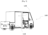
- FIG. 3 schematically illustrates a vehicle 100 of a system according to one embodiment of the invention which comprises a platform for receiving a container 10 with retractable wheels arranged opposite an access opening to the vehicle.
- This platform preferably extends at a distance less than 30 cm from the ground, preferably less than 20 cm from the ground to facilitate the loading and unloading operations described later.
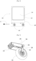
- FIG. 4 schematically illustrates a container 10 of a system according to the invention.
- This container 10 is intended to be loaded and unloaded from a vehicle 100 comprising a platform 110 which extends opposite an opening 120 for access to the vehicle.
- the particularity of the container 10 with retractable wheels of a system according to the invention and of a vehicle of a system according to the invention is that the loading and unloading of the container from the vehicle can be carried out by a single person without means of lifting. This loading and unloading can therefore be carried out anywhere and in particular near the recipients to be delivered.
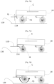
- the loading principle is described in connection with the figures 7a to 7f .
- the container comprises a box 12 comprising at least one opening 14 for access to the box to accommodate goods, not shown in the figures for the purposes of clarity.
- the container also includes rolling members 16 for moving the box in a preferred direction of advancement, and corresponding to the direction of the container when loading the container into a vehicle. This direction is represented by arrow C in the figures.
- the container also includes a box 18 for housing each rolling member arranged under the box 12.
- a single box 18 can house all of the rolling members 16.
- each rolling member can include its own box.
- the rolling members 16 are configured to be able to move from a position, called the deployed position, in which they extend outside the box 18 and thus allow the movement of the container 10 on a floor 130, and a position, called the retracted position, in which they are housed mainly in the box 18 when the container is in a vehicle.
- the particularity of the container of a system according to the invention is to obtain spontaneously by simple movement of the container towards the vehicle the tilting of the rolling members from the deployed position to the retracted position and vice versa.
- the rolling member 16 is mounted on a longitudinal frame 20 formed for example of a profile with a U-shaped transverse cross section and comprising at a first longitudinal end, three contact rollers 22 carried by the same mechanical shaft 23 which is extends on either side of the flanks of the profile forming the longitudinal reinforcement and at the opposite longitudinal end, a stirrup 24 for supporting the rolling member 16.
- This stirrup 24 comprises a first end which is mounted movable in rotation by relative to the armature 20 around a pivoting shaft 26 and an opposite end which forms a bearing of the rolling member 16.
- the base of the U-shaped profile of the longitudinal reinforcement is for example secured to the box 18 by bolting means or any equivalent means, not shown in the figures for purposes of clarity.
- the stirrup 24 also includes a locking tab 30 configured to fit into a mortise 32 formed in the lower part of the sides of the frame, directly above the locking tab when the rolling member is in the deployed position locked.
- the locking tab 30 is configured to be able to spontaneously separate by gravity from the mortise 32 when the rolling member passes from the retracted position to the free deployed position as illustrated in connection with the figures 7a to 7f .
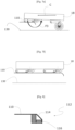
- the locking tab 30 extends transversely on either side of the sides of said frame so as to form a longitudinal stop which hinders the swinging of the rolling member by contact with the frame during unloading of the container. As illustrated on the Figure 6 , the locking tab also includes a recess which allows the passage of the rolling member 16.
- This stop 112 is represented schematically in partial section by the figure 8 and comprises an inclined portion 114 which forms an elevation stop of the container and a vertical portion 116 extending towards the ground from the elevation stop and forming a tilting stop as explained below.
- a system and a method according to the invention are mainly intended to transport containers with retractable wheels from a peri-urban storage space to urban recipients.
- the system can also include, in addition to containers with retractable wheels, means of transporting pallets.
- containers with retractable wheels means of transporting pallets.
- the same urban electric vehicle cannot simultaneously transport a container with retractable wheels and the means of transporting pallets.
- the operator uses a container with retractable wheels or pallet transport means.
- pallet transport means include, for example, a roller plate carried by a set of wheels, the plate extending at the height of the platform of the urban electric vehicle.
- the pallets can be placed by an operator (manually or by means of a suitable pallet truck) on this roller plate, then the operator moves the set of wheels surmounted by the pallets to be loaded facing the opening of the vehicle and rolls the pallets on the roller plate into the interior of the vehicle.
Landscapes
- Business, Economics & Management (AREA)
- Engineering & Computer Science (AREA)
- Economics (AREA)
- Quality & Reliability (AREA)
- Tourism & Hospitality (AREA)
- Human Resources & Organizations (AREA)
- Marketing (AREA)
- Operations Research (AREA)
- Development Economics (AREA)
- Strategic Management (AREA)
- Entrepreneurship & Innovation (AREA)
- Physics & Mathematics (AREA)
- General Business, Economics & Management (AREA)
- General Physics & Mathematics (AREA)
- Theoretical Computer Science (AREA)
- Control Of Linear Motors (AREA)
- Control Of Vehicles With Linear Motors And Vehicles That Are Magnetically Levitated (AREA)
- Handcart (AREA)
Claims (7)
- Verfahren zum Ausliefern mehrerer Pakete an mehrere Stadt-Empfänger (200) von einem stadtnahen Lagerraum aus, dadurch gekennzeichnet, dass es die Schritte umfasst, die bestehen aus:- Unterbringung (E1) der mehreren Pakete in mehrere Einziehrollencontainer, worin mindestens ein Einziehrollencontainer umfasst:o ein Gehäuse (12) mit mindestens einer Zugangsöffnung zu dem Gehäuse, um die Pakete aufzunehmen,o Rollelemente (16) zum Bewegen des Containers in einer bevorzugten Vorschubrichtung und entlang einer Hauptvorschubrichtung, der sogenannten Längsrichtung,o mindestens einen Aufnahmekasten für jedes Rollelement, der sich unterhalb des Gehäuses befindet,o worin jedes Rollelement (16) in Bezug auf das Gehäuse beweglich montiert ist, und zwar zwischen einer so genannten ausgefahrenen Position, in der es aus dem Gehäuse herausragt und die rollende Versetzung des Containers aus einem Elektro-Stadtfahrzeug heraus ermöglicht, und einer so genannten eingefahrenen Position, in der es hauptsächlich in dem Gehäuse untergebracht ist und die rollende Versetzung des Containers auf dem unteren Boden des Elektro-Stadtfahrzeugs ermöglicht, wobei der Übergang von der ausgefahrenen Position in die eingefahrene Position spontan während des Beladens des Containers in das Elektro-Stadtfahrzeug durch die Kombination der Versetzung des Gehäuses in Längsrichtung und des Kontakts zwischen dem Container und einem unter dem unteren Boden des Elektro-Stadtfahrzeug vorgesehenen Queranschlag erfolgt, und wobei der Übergang von der eingefahrenen Position in die ausgefahrene Position spontan durch die Schwerkraft während des Entladens des Containers aus dem Elektro-Stadtfahrzeug erfolgt,- Transportieren (E2) der mehreren Einziehrollencontainer in einem Radfahrzeug zu einer städtischen Logistikbasis,- Entladen (E3) der Einziehrollencontainer in die städtische Logistikbasis,- Beladen (E4) der Einziehrollencontainer in mehrere Elektro-Stadtfahrzeuge mit niedrigem Boden ohne Hebemittel,- Bewegen (E5) der mit den Containern beladenen Elektro-Stadtfahrzeuge von der städtischen Logistikbasis zu den städtischen Empfängern und Entladen der Container von den Elektro-Stadtfahrzeugen ohne Hebemittel in der Nähe der Empfänger,- Auslieferung (E6) jedes in jedem Einziehrollencontainer untergebrachten Pakets, die von jedem Elektro-Stadtfahrzeug entladen wurden, an jeden Paketempfänger.
- Zustellverfahren nach Anspruch 1, dadurch gekennzeichnet, dass der Schritt, der darin besteht, jedes Paket des von jedem Elektro-Stadtfahrzeug transportierten Containers zuzustellen (E6), zudem einen Schritt umfasst, bei dem der Einziehrollencontainer durch einen motorisierten abnehmbaren Arm bewegt wird, der es ermöglicht, den Container leichter in Fußgängerzonen oder Lagerhäusern in die Nähe der Adressaten zu bewegen.
- System zur Auslieferung mehrerer Pakete an mehrere städtische Empfänger aus einem stadtnahen Lagerbereich, welches umfasst:- mehrere Einziehrollencontainer (10), die ausgestaltet sind, die mehreren der zu befördernden Pakete aufnehmen können,- mindestens ein Radfahrzeug (20), das ausgestaltet ist, die mehreren Einziehrollencontainer (10) aufzunehmen und diese zu einer städtischen Logistikbasis zu bewegen,- mehrere Niederflur-Elektro-Stadtfahrzeuge (100), die jeweils mindestens einen Einziehrollencontainer (10) aufnehmen können und dazu bestimmt sind, jedes Paket an jeden Empfänger zu liefern, wobei die Fahrzeuge und die Container ausgestaltet sind, das Be- und Entladen jedes Einziehrollencontainers in jedem Fahrzeug ohne Hebemittel zu ermöglichen,
dadurch gekennzeichnet, dass mindestens ein Einziehrollencontainer umfasst:- ein Gehäuse (12), das mindestens eine Zugangsöffnung zum Gehäuse aufweist, um die Pakete aufzunehmen,- Rollelemente (16) zum Bewegen des Containers in einer bevorzugten Vorschubrichtung und entlang einer Hauptvorschubrichtung, der sogenannten Längsrichtung,- mindestens einen Aufnahmekasten für jedes Rollelement, der sich unter dem Gehäuse befindet,- worin jedes Rollelement (16) in Bezug auf das Gehäuse zwischen einer so genannten ausgefahrenen Position, in der es aus dem Gehäuse herausragt und die rollende Versetzung des Containers aus dem Elektro-Stadtfahrzeug heraus ermöglicht, und einer so genannten eingefahrenen Position, in der es hauptsächlich in dem Gehäuse untergebracht ist und die rollende Versetzung des Containers auf dem unteren Boden des Elektro-Stadtfahrzeugs ermöglicht, beweglich montiert ist, wobei der Übergang von der ausgefahrenen Position in die eingefahrene Position spontan während des Beladens des Containers in das Elektro-Stadtfahrzeug durch die Kombination der Versetzung des Kastens in Längsrichtung und des Kontakts zwischen dem Container und einem unter dem unteren Boden des Elektro-Stadtfahrzeugs vorgesehenen Queranschlages erfolgt, und der Übergang von der eingefahrenen Position in die ausgefahrene Position spontan durch die Schwerkraft während des Entladens des Containers aus dem Elektro-Stadtfahrzeug erfolgt. - System nach Anspruch 3, dadurch gekennzeichnet, dass es zudem für jedes Rollelement (16) einen Längsrahmen (20) umfasst, der an einem ersten Längsende mindestens eine Rolle (22) für den Kontakt mit dem Queranschlag (112) und an einem zweiten Längsende eine Halterung (24) zur Aufnahme des Rollelements (16) aufweist, die in Bezug auf den Rahmen (20) um eine Querachse drehbar montiert ist, Drehachse genannt, die es dem Rollelement (16) ermöglicht, sich beim Beladen des Containers (10) in das Fahrzeug von der ausgefahrenen Position in die eingezogene Position und umgekehrt beim Entladen des Containers (10) aus dem Fahrzeug zu bewegen, wobei jede Kontaktrolle (22) zudem ein zusätzliches Rollmittel für den Container (10) auf der horizontalen Plattform des Fahrzeugs bildet, wenn sich die Rollelemente (16) in der eingezogenen Position befinden.
- System nach Anspruch 4, dadurch gekennzeichnet, dass jede Halterung (20) zur Aufnahme des Rollelements (16) umfasst:- eine die Drehachse bildende Welle (26), die sich in einen vertikalen, länglichen Schlitz (28) erstreckt, der in dem Rahmen (20) ausgebildet ist, und die ausgestaltet ist, sich durch die Schwerkraft in dem länglichen Schlitz (28) spontan von einer Position, die als verriegelte Position bezeichnet wird, in eine Position, die als freie Position bezeichnet wird, und umgekehrt durch den Kontakt des Rollelements (16) mit dem Boden (130) zu bewegen,- eine Verriegelungsnase (30), die ausgestaltet ist, in der verriegelten Position in eine in dem Längsrahmen (20) ausgebildete Aussparung (32) einzugreifen und sich unter der Wirkung der Schwerkraft spontan zu lösen, wenn sie sich in die freie Position bewegt.
- System nach einem der Ansprüche 3 bis 5, dadurch gekennzeichnet, dass mindestens ein Elektro-Stadtfahrzeug (100) eine Plattform (110) zur Aufnahme des Containers umfasst, die gegenüber einer Zugangsöffnung (120) des Fahrzeugs angeordnet ist, dadurch gekennzeichnet, dass sich die Plattform (110) in einem Abstand von weniger als 30 cm vom Boden, vorzugsweise weniger als 20 cm vom Boden, erstreckt und größer ist als der Abstand, der in der ausgefahrenen Position der Rollelemente (16) die Schwenkachse und die Kontaktfläche der Rollelemente vom Boden trennt, und dass die Plattform (110) einen Queranschlag (112) umfasst, der unter der Plattform des Fahrzeugs vorgesehen ist und einen geneigten Abschnitt aufweist, der durch Kontakt mit den Kontaktrollen des Containers einen Höhenanschlag (114) für den Container ausbildet und es ermöglicht, die Rollelemente aus der verriegelten Position in die freie Position zu bewegen, sowie einen vertikalen Abschnitt, der sich von dem Höhenanschlag aus in Richtung des Bodens erstreckt und einen Kippanschlag (116) für das Rollelement aus der ausgefahrenen freien Position in die eingezogene Position bildet.
- System nach einem der Ansprüche 3 bis 6, dadurch gekennzeichnet, dass jedes Elektro-Stadtfahrzeug (100) zudem mit einem motorisierten abnehmbaren Arm ausgestattet ist, um die Bewegung des Containers in Fußgängerzonen oder Lagerhäusern zu erleichtern.
Priority Applications (1)
| Application Number | Priority Date | Filing Date | Title |
|---|---|---|---|
| EP21153570.3A EP4033429B1 (de) | 2021-01-26 | 2021-01-26 | Verfahren und system zur zustellung von paketen an städtischen empfängern |
Applications Claiming Priority (1)
| Application Number | Priority Date | Filing Date | Title |
|---|---|---|---|
| EP21153570.3A EP4033429B1 (de) | 2021-01-26 | 2021-01-26 | Verfahren und system zur zustellung von paketen an städtischen empfängern |
Publications (3)
| Publication Number | Publication Date |
|---|---|
| EP4033429A1 EP4033429A1 (de) | 2022-07-27 |
| EP4033429B1 true EP4033429B1 (de) | 2023-11-15 |
| EP4033429C0 EP4033429C0 (de) | 2023-11-15 |
Family
ID=74285302
Family Applications (1)
| Application Number | Title | Priority Date | Filing Date |
|---|---|---|---|
| EP21153570.3A Active EP4033429B1 (de) | 2021-01-26 | 2021-01-26 | Verfahren und system zur zustellung von paketen an städtischen empfängern |
Country Status (1)
| Country | Link |
|---|---|
| EP (1) | EP4033429B1 (de) |
Families Citing this family (1)
| Publication number | Priority date | Publication date | Assignee | Title |
|---|---|---|---|---|
| DE102022132923B4 (de) | 2022-12-12 | 2024-07-25 | Ford Global Technologies Llc | Logistiksystem |
Family Cites Families (2)
| Publication number | Priority date | Publication date | Assignee | Title |
|---|---|---|---|---|
| ITPN20030061A1 (it) * | 2003-09-19 | 2005-03-20 | Ciro Corvino | Carrello multifunzionale. |
| US20080303248A1 (en) * | 2007-06-10 | 2008-12-11 | Omar Chaparro | Portable shopping cart port-a-cart |
-
2021
- 2021-01-26 EP EP21153570.3A patent/EP4033429B1/de active Active
Also Published As
| Publication number | Publication date |
|---|---|
| EP4033429A1 (de) | 2022-07-27 |
| EP4033429C0 (de) | 2023-11-15 |
Similar Documents
| Publication | Publication Date | Title |
|---|---|---|
| CA2170385A1 (fr) | Installation mecanisee automatique de stockage d'objets | |
| FR2965257A1 (fr) | Systeme de manutention par soulevement d'une remorque | |
| EP1826092A1 (de) | Radsatz für ein Niederflur-Schienenfahrzeug und Drehgestell und Schienenfahrzeug, die einen solchen Radsatz enthalten | |
| EP4033429B1 (de) | Verfahren und system zur zustellung von paketen an städtischen empfängern | |
| EP4214140A1 (de) | Kommissionier- oder pufferspeichersystem | |
| EP3421717B1 (de) | Folgezug eines tunnelbohrers, der fördermittel für ein ausbausegment umfasst | |
| FR2944488A1 (fr) | Benne de chargement autonome destinee a recevoir une charge | |
| EP4032747A1 (de) | Mobiler warentransportbehälter und mit einem solchen behälter ausgestattetes fahrzeug | |
| EP3013639B2 (de) | Anlage zum laden und entladen von containern | |
| EP3219541B1 (de) | Anordnung von zwei fahrzeugen zur verteilung von gegenständen | |
| EP1792829B1 (de) | Verfahren, System und Vorrichtungen zum Transportieren von Container | |
| FR3037935A1 (fr) | Chariot a plateau inclinable, pour un appareil de convoyage au sol | |
| EP2252493A2 (de) | Fahrzeug zur handhabung von schwerlasten, im besonderen schienenfahrzeug und verwendung eines derartigen fahrzeuges in gegenwart eines fahrleitungssystems | |
| FR2919239A1 (fr) | Vehicule de transfert de conteneurs a bagages. | |
| FR3021614A1 (fr) | Chariot de transport d'unites de stockage et station de chargement-dechargement associee | |
| FR3109756A1 (fr) | Système porteur de chariot | |
| FR3118732A1 (fr) | Dispositif transporteur modulaire | |
| FR2864053A1 (fr) | Vehicule de transport d'objets en vrac et installation de transport | |
| FR3136203A1 (fr) | Système de support de container pour véhicule routier de transport en commun et véhicule routier de transportant en commun comprenant un tel système | |
| FR2828457A1 (fr) | Vehicules et rames ferroviaires ou routiers a niveau variable induit par roulement accessoire pour transports a grand gabarit | |
| WO2006072684A1 (fr) | Chariot d'atelier | |
| EP4281636B1 (de) | Automatisches parksystem und zugehöriges verfahren zum parken von kraftfahrzeugen | |
| CA2439548C (fr) | Systeme et methode de chargement et dechargement d'une plate forme pour vehicule routier | |
| WO2006061508A1 (fr) | Traverse mobile de support et de transfert pour le chargement et le dechargement d'une charge, sur une remorque a partir d'un camion equipe d'un bras de manutention des charges. | |
| EP1724151B1 (de) | Fahrzeug mit einer Vorrichtung zur Beladung und Entladung von Gegenständen |
Legal Events
| Date | Code | Title | Description |
|---|---|---|---|
| PUAI | Public reference made under article 153(3) epc to a published international application that has entered the european phase |
Free format text: ORIGINAL CODE: 0009012 |
|
| STAA | Information on the status of an ep patent application or granted ep patent |
Free format text: STATUS: THE APPLICATION HAS BEEN PUBLISHED |
|
| AK | Designated contracting states |
Kind code of ref document: A1 Designated state(s): AL AT BE BG CH CY CZ DE DK EE ES FI FR GB GR HR HU IE IS IT LI LT LU LV MC MK MT NL NO PL PT RO RS SE SI SK SM TR |
|
| STAA | Information on the status of an ep patent application or granted ep patent |
Free format text: STATUS: REQUEST FOR EXAMINATION WAS MADE |
|
| 17P | Request for examination filed |
Effective date: 20221220 |
|
| RBV | Designated contracting states (corrected) |
Designated state(s): AL AT BE BG CH CY CZ DE DK EE ES FI FR GB GR HR HU IE IS IT LI LT LU LV MC MK MT NL NO PL PT RO RS SE SI SK SM TR |
|
| STAA | Information on the status of an ep patent application or granted ep patent |
Free format text: STATUS: EXAMINATION IS IN PROGRESS |
|
| 17Q | First examination report despatched |
Effective date: 20230208 |
|
| GRAP | Despatch of communication of intention to grant a patent |
Free format text: ORIGINAL CODE: EPIDOSNIGR1 |
|
| STAA | Information on the status of an ep patent application or granted ep patent |
Free format text: STATUS: GRANT OF PATENT IS INTENDED |
|
| INTG | Intention to grant announced |
Effective date: 20230612 |
|
| GRAS | Grant fee paid |
Free format text: ORIGINAL CODE: EPIDOSNIGR3 |
|
| GRAA | (expected) grant |
Free format text: ORIGINAL CODE: 0009210 |
|
| STAA | Information on the status of an ep patent application or granted ep patent |
Free format text: STATUS: THE PATENT HAS BEEN GRANTED |
|
| AK | Designated contracting states |
Kind code of ref document: B1 Designated state(s): AL AT BE BG CH CY CZ DE DK EE ES FI FR GB GR HR HU IE IS IT LI LT LU LV MC MK MT NL NO PL PT RO RS SE SI SK SM TR |
|
| REG | Reference to a national code |
Ref country code: CH Ref legal event code: EP Ref country code: GB Ref legal event code: FG4D Free format text: NOT ENGLISH |
|
| REG | Reference to a national code |
Ref country code: DE Ref legal event code: R096 Ref document number: 602021006718 Country of ref document: DE |
|
| REG | Reference to a national code |
Ref country code: IE Ref legal event code: FG4D Free format text: LANGUAGE OF EP DOCUMENT: FRENCH |
|
| U01 | Request for unitary effect filed |
Effective date: 20231117 |
|
| U07 | Unitary effect registered |
Designated state(s): AT BE BG DE DK EE FI FR IT LT LU LV MT NL PT SE SI Effective date: 20231123 |
|
| PG25 | Lapsed in a contracting state [announced via postgrant information from national office to epo] |
Ref country code: GR Free format text: LAPSE BECAUSE OF FAILURE TO SUBMIT A TRANSLATION OF THE DESCRIPTION OR TO PAY THE FEE WITHIN THE PRESCRIBED TIME-LIMIT Effective date: 20240216 |
|
| PG25 | Lapsed in a contracting state [announced via postgrant information from national office to epo] |
Ref country code: IS Free format text: LAPSE BECAUSE OF FAILURE TO SUBMIT A TRANSLATION OF THE DESCRIPTION OR TO PAY THE FEE WITHIN THE PRESCRIBED TIME-LIMIT Effective date: 20240315 |
|
| PG25 | Lapsed in a contracting state [announced via postgrant information from national office to epo] |
Ref country code: ES Free format text: LAPSE BECAUSE OF FAILURE TO SUBMIT A TRANSLATION OF THE DESCRIPTION OR TO PAY THE FEE WITHIN THE PRESCRIBED TIME-LIMIT Effective date: 20231115 |
|
| PG25 | Lapsed in a contracting state [announced via postgrant information from national office to epo] |
Ref country code: IS Free format text: LAPSE BECAUSE OF FAILURE TO SUBMIT A TRANSLATION OF THE DESCRIPTION OR TO PAY THE FEE WITHIN THE PRESCRIBED TIME-LIMIT Effective date: 20240315 Ref country code: GR Free format text: LAPSE BECAUSE OF FAILURE TO SUBMIT A TRANSLATION OF THE DESCRIPTION OR TO PAY THE FEE WITHIN THE PRESCRIBED TIME-LIMIT Effective date: 20240216 Ref country code: ES Free format text: LAPSE BECAUSE OF FAILURE TO SUBMIT A TRANSLATION OF THE DESCRIPTION OR TO PAY THE FEE WITHIN THE PRESCRIBED TIME-LIMIT Effective date: 20231115 |
|
| PG25 | Lapsed in a contracting state [announced via postgrant information from national office to epo] |
Ref country code: RS Free format text: LAPSE BECAUSE OF FAILURE TO SUBMIT A TRANSLATION OF THE DESCRIPTION OR TO PAY THE FEE WITHIN THE PRESCRIBED TIME-LIMIT Effective date: 20231115 Ref country code: PL Free format text: LAPSE BECAUSE OF FAILURE TO SUBMIT A TRANSLATION OF THE DESCRIPTION OR TO PAY THE FEE WITHIN THE PRESCRIBED TIME-LIMIT Effective date: 20231115 Ref country code: NO Free format text: LAPSE BECAUSE OF FAILURE TO SUBMIT A TRANSLATION OF THE DESCRIPTION OR TO PAY THE FEE WITHIN THE PRESCRIBED TIME-LIMIT Effective date: 20240215 Ref country code: HR Free format text: LAPSE BECAUSE OF FAILURE TO SUBMIT A TRANSLATION OF THE DESCRIPTION OR TO PAY THE FEE WITHIN THE PRESCRIBED TIME-LIMIT Effective date: 20231115 |
|
| RAP2 | Party data changed (patent owner data changed or rights of a patent transferred) |
Owner name: ART ET FACON |
|
| U1K | Transfer of rights of the unitary patent after the registration of the unitary effect |
Owner name: ART ET FACON; FR |
|
| PG25 | Lapsed in a contracting state [announced via postgrant information from national office to epo] |
Ref country code: CZ Free format text: LAPSE BECAUSE OF FAILURE TO SUBMIT A TRANSLATION OF THE DESCRIPTION OR TO PAY THE FEE WITHIN THE PRESCRIBED TIME-LIMIT Effective date: 20231115 |
|
| PG25 | Lapsed in a contracting state [announced via postgrant information from national office to epo] |
Ref country code: SK Free format text: LAPSE BECAUSE OF FAILURE TO SUBMIT A TRANSLATION OF THE DESCRIPTION OR TO PAY THE FEE WITHIN THE PRESCRIBED TIME-LIMIT Effective date: 20231115 |
|
| PG25 | Lapsed in a contracting state [announced via postgrant information from national office to epo] |
Ref country code: SM Free format text: LAPSE BECAUSE OF FAILURE TO SUBMIT A TRANSLATION OF THE DESCRIPTION OR TO PAY THE FEE WITHIN THE PRESCRIBED TIME-LIMIT Effective date: 20231115 Ref country code: SK Free format text: LAPSE BECAUSE OF FAILURE TO SUBMIT A TRANSLATION OF THE DESCRIPTION OR TO PAY THE FEE WITHIN THE PRESCRIBED TIME-LIMIT Effective date: 20231115 Ref country code: RO Free format text: LAPSE BECAUSE OF FAILURE TO SUBMIT A TRANSLATION OF THE DESCRIPTION OR TO PAY THE FEE WITHIN THE PRESCRIBED TIME-LIMIT Effective date: 20231115 Ref country code: CZ Free format text: LAPSE BECAUSE OF FAILURE TO SUBMIT A TRANSLATION OF THE DESCRIPTION OR TO PAY THE FEE WITHIN THE PRESCRIBED TIME-LIMIT Effective date: 20231115 |
|
| REG | Reference to a national code |
Ref country code: DE Ref legal event code: R097 Ref document number: 602021006718 Country of ref document: DE |
|
| U21 | Renewal fee for the european patent with unitary effect paid with additional fee |
Year of fee payment: 4 Effective date: 20240712 |
|
| PG25 | Lapsed in a contracting state [announced via postgrant information from national office to epo] |
Ref country code: MC Free format text: LAPSE BECAUSE OF FAILURE TO SUBMIT A TRANSLATION OF THE DESCRIPTION OR TO PAY THE FEE WITHIN THE PRESCRIBED TIME-LIMIT Effective date: 20231115 |
|
| PG25 | Lapsed in a contracting state [announced via postgrant information from national office to epo] |
Ref country code: MC Free format text: LAPSE BECAUSE OF FAILURE TO SUBMIT A TRANSLATION OF THE DESCRIPTION OR TO PAY THE FEE WITHIN THE PRESCRIBED TIME-LIMIT Effective date: 20231115 |
|
| REG | Reference to a national code |
Ref country code: CH Ref legal event code: PL |
|
| PLBE | No opposition filed within time limit |
Free format text: ORIGINAL CODE: 0009261 |
|
| STAA | Information on the status of an ep patent application or granted ep patent |
Free format text: STATUS: NO OPPOSITION FILED WITHIN TIME LIMIT |
|
| PG25 | Lapsed in a contracting state [announced via postgrant information from national office to epo] |
Ref country code: CH Free format text: LAPSE BECAUSE OF NON-PAYMENT OF DUE FEES Effective date: 20240131 |
|
| 26N | No opposition filed |
Effective date: 20240819 |
|
| PG25 | Lapsed in a contracting state [announced via postgrant information from national office to epo] |
Ref country code: CH Free format text: LAPSE BECAUSE OF NON-PAYMENT OF DUE FEES Effective date: 20240131 |
|
| PG25 | Lapsed in a contracting state [announced via postgrant information from national office to epo] |
Ref country code: IE Free format text: LAPSE BECAUSE OF NON-PAYMENT OF DUE FEES Effective date: 20240126 |
|
| PG25 | Lapsed in a contracting state [announced via postgrant information from national office to epo] |
Ref country code: IE Free format text: LAPSE BECAUSE OF NON-PAYMENT OF DUE FEES Effective date: 20240126 |
|
| U20 | Renewal fee for the european patent with unitary effect paid |
Year of fee payment: 5 Effective date: 20250128 |
|
| PG25 | Lapsed in a contracting state [announced via postgrant information from national office to epo] |
Ref country code: CY Free format text: LAPSE BECAUSE OF FAILURE TO SUBMIT A TRANSLATION OF THE DESCRIPTION OR TO PAY THE FEE WITHIN THE PRESCRIBED TIME-LIMIT; INVALID AB INITIO Effective date: 20210126 |
|
| PG25 | Lapsed in a contracting state [announced via postgrant information from national office to epo] |
Ref country code: HU Free format text: LAPSE BECAUSE OF FAILURE TO SUBMIT A TRANSLATION OF THE DESCRIPTION OR TO PAY THE FEE WITHIN THE PRESCRIBED TIME-LIMIT; INVALID AB INITIO Effective date: 20210126 |
|
| GBPC | Gb: european patent ceased through non-payment of renewal fee |
Effective date: 20250126 |
|
| PG25 | Lapsed in a contracting state [announced via postgrant information from national office to epo] |
Ref country code: GB Free format text: LAPSE BECAUSE OF NON-PAYMENT OF DUE FEES Effective date: 20250126 |
|
| PG25 | Lapsed in a contracting state [announced via postgrant information from national office to epo] |
Ref country code: TR Free format text: LAPSE BECAUSE OF FAILURE TO SUBMIT A TRANSLATION OF THE DESCRIPTION OR TO PAY THE FEE WITHIN THE PRESCRIBED TIME-LIMIT Effective date: 20231115 |
|
| U1K | Transfer of rights of the unitary patent after the registration of the unitary effect |
Owner name: MORELLON, CLAUDE; FR |
|
| U20 | Renewal fee for the european patent with unitary effect paid |
Year of fee payment: 6 Effective date: 20260129 |