EP4033129B1 - Dbb-zwangsdichtungsventil und betätigungsvorrichtung - Google Patents
Dbb-zwangsdichtungsventil und betätigungsvorrichtung Download PDFInfo
- Publication number
- EP4033129B1 EP4033129B1 EP20865688.4A EP20865688A EP4033129B1 EP 4033129 B1 EP4033129 B1 EP 4033129B1 EP 20865688 A EP20865688 A EP 20865688A EP 4033129 B1 EP4033129 B1 EP 4033129B1
- Authority
- EP
- European Patent Office
- Prior art keywords
- sealing member
- valve
- driving part
- member driving
- dbb
- Prior art date
- Legal status (The legal status is an assumption and is not a legal conclusion. Google has not performed a legal analysis and makes no representation as to the accuracy of the status listed.)
- Active
Links
Images


Classifications
-
- F—MECHANICAL ENGINEERING; LIGHTING; HEATING; WEAPONS; BLASTING
- F16—ENGINEERING ELEMENTS AND UNITS; GENERAL MEASURES FOR PRODUCING AND MAINTAINING EFFECTIVE FUNCTIONING OF MACHINES OR INSTALLATIONS; THERMAL INSULATION IN GENERAL
- F16K—VALVES; TAPS; COCKS; ACTUATING-FLOATS; DEVICES FOR VENTING OR AERATING
- F16K31/00—Actuating devices; Operating means; Releasing devices
- F16K31/44—Mechanical actuating means
-
- F—MECHANICAL ENGINEERING; LIGHTING; HEATING; WEAPONS; BLASTING
- F16—ENGINEERING ELEMENTS AND UNITS; GENERAL MEASURES FOR PRODUCING AND MAINTAINING EFFECTIVE FUNCTIONING OF MACHINES OR INSTALLATIONS; THERMAL INSULATION IN GENERAL
- F16K—VALVES; TAPS; COCKS; ACTUATING-FLOATS; DEVICES FOR VENTING OR AERATING
- F16K5/00—Plug valves; Taps or cocks comprising only cut-off apparatus having at least one of the sealing faces shaped as a more or less complete surface of a solid of revolution, the opening and closing movement being predominantly rotary
- F16K5/06—Plug valves; Taps or cocks comprising only cut-off apparatus having at least one of the sealing faces shaped as a more or less complete surface of a solid of revolution, the opening and closing movement being predominantly rotary with plugs having spherical surfaces; Packings therefor
- F16K5/0605—Plug valves; Taps or cocks comprising only cut-off apparatus having at least one of the sealing faces shaped as a more or less complete surface of a solid of revolution, the opening and closing movement being predominantly rotary with plugs having spherical surfaces; Packings therefor with particular plug arrangements, e.g. particular shape or built-in means
-
- F—MECHANICAL ENGINEERING; LIGHTING; HEATING; WEAPONS; BLASTING
- F16—ENGINEERING ELEMENTS AND UNITS; GENERAL MEASURES FOR PRODUCING AND MAINTAINING EFFECTIVE FUNCTIONING OF MACHINES OR INSTALLATIONS; THERMAL INSULATION IN GENERAL
- F16K—VALVES; TAPS; COCKS; ACTUATING-FLOATS; DEVICES FOR VENTING OR AERATING
- F16K5/00—Plug valves; Taps or cocks comprising only cut-off apparatus having at least one of the sealing faces shaped as a more or less complete surface of a solid of revolution, the opening and closing movement being predominantly rotary
- F16K5/06—Plug valves; Taps or cocks comprising only cut-off apparatus having at least one of the sealing faces shaped as a more or less complete surface of a solid of revolution, the opening and closing movement being predominantly rotary with plugs having spherical surfaces; Packings therefor
- F16K5/0647—Spindles or actuating means
-
- F—MECHANICAL ENGINEERING; LIGHTING; HEATING; WEAPONS; BLASTING
- F16—ENGINEERING ELEMENTS AND UNITS; GENERAL MEASURES FOR PRODUCING AND MAINTAINING EFFECTIVE FUNCTIONING OF MACHINES OR INSTALLATIONS; THERMAL INSULATION IN GENERAL
- F16K—VALVES; TAPS; COCKS; ACTUATING-FLOATS; DEVICES FOR VENTING OR AERATING
- F16K5/00—Plug valves; Taps or cocks comprising only cut-off apparatus having at least one of the sealing faces shaped as a more or less complete surface of a solid of revolution, the opening and closing movement being predominantly rotary
- F16K5/06—Plug valves; Taps or cocks comprising only cut-off apparatus having at least one of the sealing faces shaped as a more or less complete surface of a solid of revolution, the opening and closing movement being predominantly rotary with plugs having spherical surfaces; Packings therefor
- F16K5/0663—Packings
- F16K5/0694—Spindle sealings
-
- F—MECHANICAL ENGINEERING; LIGHTING; HEATING; WEAPONS; BLASTING
- F16—ENGINEERING ELEMENTS AND UNITS; GENERAL MEASURES FOR PRODUCING AND MAINTAINING EFFECTIVE FUNCTIONING OF MACHINES OR INSTALLATIONS; THERMAL INSULATION IN GENERAL
- F16K—VALVES; TAPS; COCKS; ACTUATING-FLOATS; DEVICES FOR VENTING OR AERATING
- F16K5/00—Plug valves; Taps or cocks comprising only cut-off apparatus having at least one of the sealing faces shaped as a more or less complete surface of a solid of revolution, the opening and closing movement being predominantly rotary
- F16K5/08—Details
- F16K5/14—Special arrangements for separating the sealing faces or for pressing them together
- F16K5/20—Special arrangements for separating the sealing faces or for pressing them together for plugs with spherical surfaces
- F16K5/204—Special arrangements for separating the sealing faces or for pressing them together for plugs with spherical surfaces with the plugs or parts of the plugs mechanically pressing the seals against the housing
Definitions
- the present disclosure belongs to a forced sealing valve, and in particular relates to a double block and bleed (DBB) forced sealing valve and an operating device.
- DBB double block and bleed
- a DBB forced sealing valve has outstanding sealing performance. While the valve is in a closed position, its sealing integration can be verified with valve inline and under pressure, which ensures the reliability of valve closing.
- DBB forced sealing valves are needed for many important applications. For example, in a tank farm, different storage tanks are usually used to store different media which have to be strictly isolated to prevent any potential huge loss caused by contamination of the media. Hence, DBB forced sealing valves must be used for isolation valves of the tanks and shut-off valves of the tank farm. Similarly, in oil or natural gas metering, airport fuel systems, and other scenarios that require verifiable tight shut-off, the application of DBB forced sealing valves is always mandatorily required by major international codes and standards.
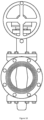
- DBB forced sealing valves on the market are a kind of expansion plug valves, as shown in Figure 10 .
- the valve core is composed of a wedge plug and two discs on both sides.
- the valve core rotates friction free between the on/off positions.
- the wedge plug is driven down by the valve stem, and the discs are pushed through the wedge inclined surfaces to achieve a forced seal.
- the valve stem has to complete complex rotational and linear movements through a complicated operating mechanism during the entire valve opening and closing operations. Since the linear movement of the valve stem is in the same direction as the escape of medium, leaking at the stem of this kind of valve can easily occur.
- the complicated operating mechanism is arranged at the valve stem, so that the size of the valve stem part of this kind of valve is huge, usually more than double the height of the valve body.
- the valve core has to adopt a geometric shape similar to that of a plug valve. Limited by its geometric structure, if the flow passage of this kind of valve adopts a full port, the valve body will be very large. Therefore, such valves usually have to adopt reduced port designs, such as a rectangle or a rhombus passage. Such a compromise design has a huge impact on the flow capacity of the valve.
- FR1461479 discloses a DBB forced sealing valve, including: a valve body; valve seats; a valve core arranged in the valve body; an upper sealing member driving part and a lower sealing member driving part arranged in the valve body and located on either side of the valve core; sealing members arranged between the valve seats and the upper and the lower sealing member driving parts; wherein, the upper sealing member driving part and the lower sealing member driving part can move along a rotation axis of the valve core, and the upper sealing member driving part and the lower sealing member driving part drive the sealing members to press against or to retract from the valve seats.
- the purpose of the present disclosure is to propose a technical solution for a DBB forced sealing valve and an operating device, optimize the structural design of DBB forced sealing valves, improve the sealing reliability at the valve stem, improve the flow capacity of the valve, and make the operating mechanism simple and reliable in structure.
- a DBB forced sealing valve characterised in that the upper sealing member driving part is provided with an upper driving track for driving the sealing members and the lower sealing member driving part is provided with a lower driving track for driving the sealing members and wherein the upper driving track and the lower driving track are dovetail, the upper driving track is inclined to the axis of rotation of the valve core and the lower driving track is inclined to the axis of rotation of the valve core.
- valve core is provided with a flow passage; and the upper sealing member driving part and the lower sealing member driving part are located on each side of the flow passage.
- the DBB forced sealing valve includes a valve stem that drives the valve core to rotate.
- the DBB forced sealing valve further includes an upper driving shaft and a lower driving shaft located on the valve core and on each side of the flow passage.
- the upper driving shaft and the lower driving shaft drive the upper sealing member driving part and the lower sealing member driving part to move along the rotation axis of the valve core through threads.
- the threads of the upper driving shaft and the lower driving shaft are in opposite directions.
- the lower sealing member driving part is provided with guiding holes; the upper sealing member driving part is provided with guiding bars correspondingly inserted into the guiding holes.
- valve body includes a valve bonnet; the valve bonnet is provided with a limiting groove; the upper sealing member driving part is provided with a limiting rod corresponding to the limiting groove to limit the rotation stroke of the upper sealing member drive part.
- one end of the valve stem is provided with a hexagonal head; one end of the upper driving shaft is provided with an inner hexagonal hole; the hexagonal head is located in the inner hexagonal hole and fits with the inner hexagonal hole.
- the DBB forced sealing valve includes a locking rocker arm set in the upper sealing member driving part; and a rocker arm base surface provided in the valve body.
- the rocker arm base surface is provided with a locking guide groove.
- the valve core drives the upper and lower sealing member driving parts to rotate within a rotation stroke between an open position and a closed position.
- the valve core toggles the rocker arm to enter the locking guide groove, and the valve core continues to rotate towards the closing direction, driving the upper sealing member driving part to move along the rotation axis of the valve core.
- the locking rocker arm moves in the locking guide groove.
- the locking rocker arm is provided with a rotating rocker.
- the valve core is provided with a rocker guide groove and a rocker guide surface.
- the rotating rocker is embedded in the rocker guide groove, and the locking rocker arm moves under the restriction of the base surface of the rocker arm.
- the valve core also drives the sealing member driving part to rotate.
- the rocker guide groove rotates the locking rocker arm through the rotating rocker, and the locking rocker arm enters the locking guide groove.
- the rotating rocker moves on the rocker guide surface.
- the rocker guide groove is provided at a starting end of the rocker guide surface.
- the opening end of the locking guide groove is provided with a transition groove.
- the beneficial features of the present disclosure are: a balanced design is adopted for the valve core, which completely solves the problems of the rising valve stems used in the current DBB forced sealing valves. This greatly simplifies the structure of the valve stem and greatly improves the sealing reliability of the valve stem. More importantly, upper and lower sealing member driving parts are adopted to drive the motion and forced sealing of the sealing members via a two-way slope. This can effectively reduce the structural size of the valve and essentially optimise the geometric shape of the valve core. Consequently, the valve flow passage can naturally adopt a round shape to match the shape of the pipeline, which greatly improves the flow capacity of the valve and makes the overall size of the valve body very compact.
- the geometric optimization of the upper sealing member driving part, the lower sealing member driving part and the valve core also allows the valve body structure to differ from the complex casting valve body structure that the current DBB forced sealing valves have to adopt.
- the valve body of the DBB forced sealing valve in the present disclosure can flexibly adopt the side-entry structure, the top-entry structure or the all-welded structure of ordinary ball valves, and thus can easily adapt to a variety of applications.
- the valve core is used to drive the rocker arm; this mechanism makes the structure of the valve compact and the opening and closing of the valve convenient and reliable.
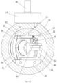
- a DBB forced sealing valve includes a valve body 10, a valve seat 20, and a valve stem 30.
- the valve stem drives the valve core 40 to rotate.
- the valve core is provided with a flow passage 41.
- An upper sealing member driving part 50 and a lower sealing member driving part 60 are provided on either side of the flow passage respectively.
- An upper drive shaft 47 and a lower drive shaft 48 are provided on either side of the valve core flow passage respectively.
- the upper drive shaft and the lower drive shaft drive the upper sealing member driving part and the lower sealing member driving part using threads.
- the threads direction of the upper drive shaft is opposite to the threads direction of the lower drive shaft.
- the upper sealing member driving part is provided with an upper driving track 51 for driving the sealing member, and the upper driving track is inclined relative to the rotation axis of the valve core;
- the lower sealing member driving part is provided with a lower driving track 61 for driving the sealing member, and the lower driving track is inclined relative to the rotation axis of the valve core.
- the upper driving track and the lower driving track are dovetail tracks.
- a DBB forced sealing valve operating device the DBB forced sealing valve is provided with a valve body 10, a valve core 40 and an upper sealing member driving part 50.
- the valve core is provided with a flow passage 41.
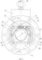
- the above-mentioned upper sealing member driving part rotates between the open position (as shown in Figure 4 ) and the closed position (as shown in Figure 1 ).
- the valve core drives the upper sealing member driving part to rotate.
- the upper sealing member driving part is provided with a locking rocker arm 52.
- the valve body is provided with a rocker arm base surface 17; the rocker arm base surface is provided with a locking guide groove 11.
- the valve body is provided with an open stop and closed stop.
- valve core pushes the locking rocker arm into the locking guide groove (as shown in Figure 7 ), and the valve core continues to rotate in the closing direction (i.e. the R2 direction in Figure 4 ) to drive the upper sealing member driving part to move along the rotation axis of the valve core.
- the locking rocker arm moves in the locking guide groove (as shown in Figures 8 and 9 ).
- the locking rocker arm is provided with a rotating rocker 53.
- the valve core is provided with a rocker guide groove 44 and a rocker guide surface 45.
- the upper sealing member driving part rotates between the open position and the closed position (as shown in the Figures 5 and 6 )
- the rotating rocker is embedded in the rocker guide groove.
- the locking rocker arm moves under the restriction of the base surface of the rocker arm, and the valve core drives the upper sealing member driving part to rotate.
- the rocker guide groove pushes the locking rocker arm to rotate using the rotating rocker, the locking rocker arm enters the locking guide groove, and the rotating rocker moves on the rocker guide surface.
- the rocker guide groove is provided at the starting end of the rocker guide surface.
- the opening of the locking guide groove is provided with a transition groove 12, and in some working conditions, when the upper sealing member driving part rotates to the closed position, the locking rocker arm enters the locking guide groove through the transition groove.
- a DBB forced sealing valve includes a valve body 10, a valve seat 20 and a valve stem 30.
- the valve body described in this disclosure is a valve body of a broad concept, including a valve body 10.
- the valve body is cylindrical.
- a valve bonnet 1A is provided on the upper side of the valve body.
- the valve bonnet and the valve body are provided with a through shaft hole 14.
- the valve stem is installed in the shaft hole.
- An upper bearing block 1B is provided on the upper side of the valve body, and a lower bearing block 1C is provided on the lower side of the valve body.
- the upper bearing block and the lower bearing block are respectively provided with bearing holes (15, 16).
- the valve body 10, the valve bonnet 1A, the upper bearing block 1B and the lower bearing block 1C are fixedly connected as a whole to form a generalized valve body.
- Sealing ring 32 is provided between the valve stem and the valve bonnet.
- valve seat 20 Either end of the valve body is respectively provided with a generalized valve seat 20 (a valve seat in this embodiment is an assembly of a valve seat and a valve end).
- a valve core 40 is installed in the valve body.
- the valve core is installed in the valve body through the bearing hole of the upper bearing block 1B and that of the lower bearing block 1C.
- a valve core ball 43 is provided at the centre of the valve core.
- a flow passage 41 is provided at the centre of the valve core ball; the flow passage is a circular through hole and the diameter D of the flow passage is identical to the diameter of the pipe on which the DBB forced sealing valve is installed such that the medium in the pipe can flow smoothly.
- the upper end of the valve core ball is provided with an upper drive shaft 47, and the lower end of the valve core ball is provided with a lower drive shaft 48.
- the upper drive shaft and the lower drive shaft are provided with threads, and the threads direction of the upper drive shaft is opposite to that of the lower drive shaft.
- An inner hexagonal hole 46 is provided at the top of the upper drive shaft.
- a hexagonal head 31 corresponding to the inner hexagonal hole of the valve core is provided on the lower end of the valve stem.
- the valve stem drives the valve core 40 to rotate via the hexagonal head; the valve stem can also drive the valve core via other driving connections.
- An upper sealing member driving part 50 and a lower sealing member driving part 60 are respectively provided on either side of the flow passage of the valve core.
- the upper sealing member driving part is provided with a threaded hole 55 to be meshed with the threads of the upper drive shaft of the valve core.
- the lower sealing member driving part is provided with a threaded hole 62 to be meshed with the threads of the lower drive shaft of the valve core.
- the lower sealing member driving part is provided with four guide holes 63, and the upper sealing member driving part is provided with four guide rods 56 corresponding to the guide holes so that the upper sealing member driving part and the lower sealing member driving part can move coaxially and synchronously.
- the valve core drives the upper sealing member driving part and the lower sealing member driving part to move in opposite directions using threads.
- Either side of the upper sealing member driving part is provided with an upper driving track 51 for driving the sealing members.
- the upper driving track is inclined to the rotation axis of the valve core at its upper end; the angle between the upper driving track and the rotation axis of the valve core is ⁇ 1.
- Either side of the lower sealing member driving part is provided with a lower driving track 61 for driving the sealing members.
- the upper sealing member driving part and the lower sealing member driving part are respectively provided with a sealing member 70 on either side.
- the sealing members are provided with an upper guide groove 71 to be matched with the upper driving track 51, and a lower guide groove 72 to be matched with the lower driving track 61.
- valve core When the valve core rotates, it drives the upper sealing member driving part and the lower sealing member driving part to move along the rotation axis of the valve core in opposite directions.
- the upper sealing member driving part and the lower sealing member driving part move away from the flow passage.
- the upper sealing member driving part and the lower sealing member driving part drive the sealing members to move outward, pressing against the valve seats.
- the upper sealing member driving part and the lower sealing member driving part move towards the flow passage.
- the upper sealing member driving part and the lower sealing member driving part drive the sealing members to retract from the valve seats.
- the upper driving track and the lower driving track are dovetail tracks, which are compact and provide stable transmission.
- the DBB forced sealing valve of this embodiment retains the excellent sealing performance of the DBB forced sealing valves currently in the market. It provides a round passage for the medium in the valve.
- the diameter of the medium passage is identical to the diameter of the pipeline, allowing smooth flow of the medium.
- the upper sealing member driving part and the lower sealing member driving part drive the motion and the forced sealing of the sealing members via a two-way slope. This effectively reduces the structural size of the valve and is suitable for various pipeline installation occasions.
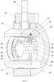
- a DBB forced sealing valve operating device As shown in Figures 1 to 4 , a DBB forced sealing valve operating device, the operating device of this embodiment is the operating device of the DBB forced sealing valve described in the first embodiment.
- the forced sealing valve is provided with a valve body 10, a rotatable valve core 40 and an upper sealing member driving part 50.
- the valve core is provided with a flow passage 41, and the valve core drives the upper sealing member driving part to rotate between the open position (shown in Figure 4 ) and the closed position (shown in Figure 1 ).
- the valve core rotates relative to the upper sealing member driving part, it drives the upper sealing member driving part via the thread to make the sealing member move along the axis of rotation of the valve core, so that the sealing member moves towards or retracts from the valve seat, realizing the forced sealing or opening of the valve.
- the DBB forced sealing valve requires a set of operating mechanism.
- the valve stem in a one-way rotation stroke drives the sealing member to rotate 90° to reach its closed position and achieves forced sealing.
- the valve stem in a one-way rotation stroke lifts the sealing of the sealing member and drives the sealing member to rotate 90° to reach its open position.
- the upper sealing member driving part is provided with a locking rocker arm 52; the axis of rotation of the locking rocker arm is perpendicular to the axis of rotation of the valve core.
- the locking rocker arm is provided with a rotating rocker 53.
- the bottom surface 17 of the upper bearing block 1B of the valve body is the rocker arm base surface; the rocker arm base surface is provided with a locking guide groove 11 and an arc-shaped transition groove 12 is provided at the opening of the locking guide groove.
- the valve core ball 43 is provided with a rocker guide groove 44 and a rocker guide surface 45, and the rocker guide surface is a spiral surface surrounding the valve core ball.
- the rocker guide groove is arranged at the starting end of the rocker guide surface, and this starting end refers to the front end of the valve core when the valve core rotates in the closing direction.
- the upper sealing member driving part rotates between an open position and a closed position with a rotation stroke of 90°.
- the valve bonnet 1A is provided with a limit groove 13
- the upper sealing member driving part is provided with a limit rod 54 which corresponds to the limit groove 13.
- the limit groove and the limit rod limits the rotation stroke of the upper sealing member driving part.
- the valve stem drives the valve core to rotate in the closing direction (R2 direction as shown in Figure 4 ).
- the upper sealing member driving part turns to the closed position, it stops rotating.
- the rocker guide groove 44 of the valve core pushes via the rotating rocker 53 the locking rocker arm 52 to rotate.
- the locking rocker arm enters the locking guide groove 11.
- the rotating rocker moves away from the rocker guide groove 44 (as shown in Figure 7 ) and moves on the rocker guide surface 45.
- the upper sealing member driving part rotates freely with the valve core, and the locking rocker arm can also rotate freely with the upper sealing member driving part.
- the top end of the locking rocker arm does not contact the base surface 17 of the rocker arm.
- a rolling bearing 57 is provided at the top of the locking rocker arm in this embodiment. During such motion, due to the force provided by the rocker guide groove 44, the top of the locking rocker arm 52 can directly enter the locking guide groove 11.
- the valve core continues to rotate in the closing direction (i.e. the R2 direction as shown in Figure 4 ), and drives via the upper drive shaft 47 the upper sealing member driving part to move upwards along the valve core rotation axis.
- the locking rocker arm moves in the locking guide groove (as shown in Figures 8-9 ).
- the valve core drives via the lower drive shaft 48 the lower sealing member driving part to move downwards along the valve core rotation axis.
- the valve core rotates in the opening direction (i.e. the R1 direction in Figure 4 ). Since the locking rocker arm 52 is in the locking guide groove 11, the position of the upper sealing member driving part is locked and so the upper sealing member driving part does not rotate with the valve core.
- the valve core simultaneously drives via the upper drive shaft 47 and the lower drive shaft 48 the upper and lower sealing member driving parts to move along the valve core rotation axis. This realizes the mechanism described in the first embodiment: "the upper and lower sealing member driving parts move towards the flow passage and drive the sealing members to retract from the valve seats.”
- the rocker guide groove 44 matches the position of the transition groove 12 (as illustrated in Figure 7 )
- the rocker guide groove pushes the rocker.
- the locking rocker arm leaves the locking guide groove (as illustrated in Figure 6 ).
- the top of the locking rocker arm is lower than the rocker arm base surface 17.
- the locking rocker arm stops rotating when contacts the upper sealing member driving part.
- the valve core continues to rotate in the opening direction.
- the rocker guide groove drives via the rotating rocker the upper sealing member driving part to rotate along with the valve core to the open position (refer to Figure 4 ).
- the present disclosure adopts a mechanism where the valve core drives the rocker arm; this mechanism is compact in size, which makes the opening and closing operations of the valve convenient and reliable.
Landscapes
- Engineering & Computer Science (AREA)
- General Engineering & Computer Science (AREA)
- Mechanical Engineering (AREA)
- Sliding Valves (AREA)
- Taps Or Cocks (AREA)
Claims (12)
- DBB-Zwangsabdichtungsventil, das Folgendes enthält:einen Ventilkörper (10);Ventilsitze (20);einen Ventileinsatz (40), der im Ventilkörper (10) angeordnet ist;ein oberes Dichtungselement-Antriebsteil (50) und ein unteres Dichtungselement-Antriebsteil (60), die im Ventilkörper (10) angeordnet sind und sich auf beiden Seiten des Ventileinsatzes (40) befinden;Dichtungselemente (70), die zwischen den Ventilsitzen (20) und dem oberen und dem unteren Dichtungselement-Antriebsteil (50, 60) angeordnet sind;wobei das obere Dichtungselement-Antriebsteil (50) und das untere Dichtungselement-Antriebsteil (60) sich entlang einer Drehachse des Ventileinsatzes (40) bewegen können, und das obere Dichtungselement-Antriebsteil (50) und das untere Dichtungselement-Antriebsteil (60) die Dichtungselemente (70) antreiben, um gegen die Ventilsitze (20) zu drücken oder sich von diesen zurückzuziehen;dadurch gekennzeichnet, dass das obere Dichtungselement-Antriebsteil (50) mit einer oberen Antriebsspur (51) zum Antreiben der Dichtungselemente (70) versehen ist und das untere Dichtungselement-Antriebsteil (60) mit einer unteren Antriebsspur (61) zum Antreiben der Dichtungselemente (70) versehen ist, und wobei die obere Antriebsspur (51) und die untere Antriebsspur (61) Schwalbenschwanzspuren sind, die obere Antriebsspur (51) zur Drehachse des Ventileinsatzes (40) geneigt ist und die untere Antriebsspur (61) zur Drehachse des Ventileinsatzes (40) geneigt ist.
- DBB-Zwangsabdichtungsventil nach Anspruch 1, wobei der Ventileinsatz (40) mit einem Strömungskanal (41) versehen ist; und sich das obere und das untere Dichtungselement-Antriebsteil (50, 60) auf beiden Seiten des Strömungskanals (41) befinden.
- DBB-Zwangsabdichtungsventil nach Anspruch 2, wobei das DBB-Zwangsabdichtungsventil einen Ventilschaft (30) umfasst, der den Ventileinsatz (40) zum Drehen antreibt.
- DBB-Zwangsabdichtungsventil nach Anspruch 3, wobei das DBB-Zwangsabdichtungsventil ferner eine obere Antriebswelle (47) und eine untere Antriebswelle (48) umfasst, die auf dem Ventileinsatz (40) angeordnet sind und sich jeweils auf beiden Seiten des Strömungskanals (41) befinden; wobei die obere Antriebswelle (47) und die untere Antriebswelle (48) das obere Dichtungselement-Antriebsteil (50) und das untere Dichtungselement-Antriebsteil (60) mit Hilfe von Gewinden so antreiben, dass sie sich entlang der Drehachse des Ventileinsatzes (40) bewegen.
- DBB-Zwangsabdichtungsventil nach Anspruch 4, wobei die Gewinderichtung der oberen Antriebswelle (47) der Gewinderichtung der unteren Antriebswelle (48) entgegengesetzt ist.
- DBB-Zwangsabdichtungsventil nach Anspruch 1, wobei das untere Dichtungselement-Antriebsteil (60) mit Führungslöchern (63) versehen ist; wobei das obere Dichtungselement-Antriebsteil (50) mit Führungsstangen (56) versehen ist, die zu den Führungslöchern (63) passen.
- DBB-Zwangsabdichtungsventil nach Anspruch 1, wobei der Ventilkörper (40) einen Ventildeckel (1A) enthält, der Ventildeckel (1A) mit einer Begrenzungsnut (13) versehen ist und das obere Dichtungselement-Antriebsteil (50) mit einer Begrenzungsstange (54) versehen ist, die mit der Begrenzungsnut (13) zusammenpasst, um den Drehhub des oberen Dichtungselement-Antriebsteils (50) zu begrenzen.
- DBB-Zwangsabdichtungsventil nach Anspruch 3, wobei ein Ende des Ventilschafts (30) mit einem Sechskantkopf (31) versehen ist; ein Ende der oberen Antriebswelle (47) mit einem inneren Sechskantloch (46) versehen ist; und der Sechskantkopf (31) in das innere Sechskantloch (46) eingepasst ist.
- DBB-Zwangsabdichtungsventil nach Anspruch 1, das Folgendes enthält:einen Verriegelungskipphebel (52), der im oberen Dichtungselement-Antriebsteil (50) vorgesehen ist;eine Kipphebelbasisfläche (17), die im Ventilkörper (40) vorgesehen ist, wobei die Kipphebelbasisfläche (17) mit einer Verriegelungsführungsnut (11) versehen ist;wobei der Ventileinsatz (40) das obere und das untere Dichtungselement-Antriebsteil (50, 60) zum Drehen innerhalb eines Drehhubs zwischen einer geöffneten Position und einer geschlossenen Position antreibt; wenn sich das obere und das untere Dichtungselement-Antriebsteil (50, 60) in die geschlossene Position drehen, der Ventileinsatz (40) den Verriegelungskipphebel (52) in die Verriegelungsführungsnut (11) drückt; der Ventileinsatz (40) sich weiter in die Schließrichtung dreht und das obere und das untere Dichtungselement-Antriebsteil (50, 60) zum Bewegen entlang der Drehachse des Ventileinsatzes (40) antreibt; und der Verriegelungskipphebel (52) sich in der Verriegelungsführungsnut (11) bewegt.
- DBB-Zwangsabdichtungsventil nach Anspruch 9, wobei der Verriegelungskipphebel (52) mit einer drehbaren Kippvorrichtung (53) versehen ist und der Ventileinsatz (40) mit einer Kippvorrichtungs-Führungsnut (44) und einer Kippvorrichtungs-Führungsfläche (45) versehen ist; wenn das obere und das untere Dichtungselement-Antriebsteil (50, 60) sich zwischen der geöffneten Position und der geschlossenen Position drehen, die drehbare Kippvorrichtung (53) in der Kippvorrichtungs-Führungsnut (44) eingebettet ist; der Verriegelungskipphebel (52) sich unter der Beschränkung der Kipphebelbasisfläche (17) bewegt, und der Ventileinsatz (40) das obere und das untere Dichtungselement-Antriebsteil (50, 60) zum Drehen antreibt; wenn das obere und das untere Dichtungselement-Antriebsteil (50, 60) sich in die geschlossene Position drehen, die Kipphebel-Führungsnut (44) den Verriegelungskipphebel (52) über die drehbare Kippvorrichtung (53) drückt, der Verriegelungskipphebel (52) in die Verriegelungsführungsnut (44) eintritt und sich die drehbare Kippvorrichtung (53) auf der Kipphebel-Führungsfläche (45) bewegt.
- DBB-Zwangsabdichtungsventil nach Anspruch 9, wobei die Kipphebelführungsnut (44) an einem Anfangsende der Kipphebelführungsfläche (45) vorgesehen ist.
- DBB-Zwangsabdichtungsventil nach Anspruch 9, wobei die Öffnung der Verriegelungsführungsnut (44) mit einer Übergangsnut (12) versehen ist und der Verriegelungskipphebel (52) durch die Übergangsnut (12) in die Verriegelungsführungsnut (44) eintritt, wenn sich das obere und das untere Dichtungselement-Antriebsteil (50, 60) in die geschlossene Position drehen.
Applications Claiming Priority (2)
| Application Number | Priority Date | Filing Date | Title |
|---|---|---|---|
| CN201910889922.5A CN110594442B (zh) | 2019-09-20 | 2019-09-20 | 一种dbb强制密封阀及操作装置 |
| PCT/CN2020/105504 WO2021052018A1 (zh) | 2019-09-20 | 2020-07-29 | 一种dbb强制密封阀及操作装置 |
Publications (4)
| Publication Number | Publication Date |
|---|---|
| EP4033129A1 EP4033129A1 (de) | 2022-07-27 |
| EP4033129A4 EP4033129A4 (de) | 2023-11-08 |
| EP4033129B1 true EP4033129B1 (de) | 2025-03-26 |
| EP4033129C0 EP4033129C0 (de) | 2025-03-26 |
Family
ID=68861368
Family Applications (1)
| Application Number | Title | Priority Date | Filing Date |
|---|---|---|---|
| EP20865688.4A Active EP4033129B1 (de) | 2019-09-20 | 2020-07-29 | Dbb-zwangsdichtungsventil und betätigungsvorrichtung |
Country Status (5)
| Country | Link |
|---|---|
| EP (1) | EP4033129B1 (de) |
| JP (1) | JP7490253B2 (de) |
| CN (1) | CN110594442B (de) |
| CA (1) | CA3120214C (de) |
| WO (1) | WO2021052018A1 (de) |
Families Citing this family (9)
| Publication number | Priority date | Publication date | Assignee | Title |
|---|---|---|---|---|
| CN110594442B (zh) * | 2019-09-20 | 2021-07-06 | 淄博沃泰斯石化设备有限公司 | 一种dbb强制密封阀及操作装置 |
| CN111156328B (zh) * | 2020-01-20 | 2021-07-06 | 上海亚奥阀门有限公司 | 一种锻钢硬密封浮动球阀 |
| CN112096905B (zh) * | 2020-07-27 | 2022-06-10 | 国家石油天然气管网集团有限公司华南分公司 | 一种盘式电机协同面凸轮驱动阀芯阀座分离型无摩擦球阀 |
| CN112096904B (zh) * | 2020-07-27 | 2022-06-10 | 国家石油天然气管网集团有限公司华南分公司 | 一种盘式电机协同面凸轮驱动伸缩式无摩擦球阀 |
| CN112096906B (zh) * | 2020-07-27 | 2023-01-03 | 西安交通大学 | 一种直线和旋转电机协同驱动的伸缩式无摩擦球阀 |
| CN112096899B (zh) * | 2020-07-27 | 2022-04-08 | 国家石油天然气管网集团有限公司华南分公司 | 锥形电机伺服直驱式伸缩型无摩擦球阀 |
| CN114367551B (zh) * | 2020-10-15 | 2024-03-26 | 北京京诚瑞信长材工程技术有限公司 | 分水阀组和用于长材优特钢生产线的多通道水冷装置 |
| CN115614494A (zh) * | 2022-09-21 | 2023-01-17 | 山东新一代信息产业技术研究院有限公司 | 一种用于清洁机器人的电动阀门装置 |
| CN119467757B (zh) * | 2024-10-09 | 2025-12-02 | 河南宇宙流体科技有限公司 | 一种带导流孔的全通径偏心球阀 |
Family Cites Families (15)
| Publication number | Priority date | Publication date | Assignee | Title |
|---|---|---|---|---|
| GB285446A (en) * | 1927-02-16 | 1928-06-28 | Schaeffer & Budenberg Gmbh | An improved stop valve |
| US2531759A (en) * | 1947-10-21 | 1950-11-28 | Reed Roller Bit Co | Valve |
| FR1461479A (fr) * | 1965-09-08 | 1966-02-25 | Ratier Figeac Soc | Vanne |
| JPS6135270U (ja) * | 1984-07-31 | 1986-03-04 | 日立プラント建設株式会社 | ダブルブロツクボ−ル弁 |
| JP3119219B2 (ja) * | 1997-11-07 | 2000-12-18 | 岡バルブ製造株式会社 | カートリッジ式のボールバルブ |
| CN201672086U (zh) * | 2010-05-17 | 2010-12-15 | 上海罗托克自动化仪表有限公司 | 微动力轻启式轨道球阀 |
| CN203585399U (zh) * | 2013-10-24 | 2014-05-07 | 铜陵市经纬流体科技有限公司 | 软密封球阀阀芯结构 |
| CN103742666B (zh) * | 2013-12-13 | 2016-02-10 | 四川大学 | 一种撑开式轨道球阀 |
| KR101545811B1 (ko) * | 2014-03-25 | 2015-08-24 | 안효득 | 와류 방지용 컨트롤 밸브 |
| CN205504056U (zh) * | 2016-03-01 | 2016-08-24 | 江苏神通阀门股份有限公司 | 一种低扭矩球阀 |
| CN205877247U (zh) * | 2016-05-26 | 2017-01-11 | 刘晓琦 | 一种强制密封球阀 |
| CN207261704U (zh) * | 2017-08-24 | 2018-04-20 | 成都成高阀门有限公司 | 一种撑开式强制密封球阀 |
| CN208123504U (zh) * | 2018-02-07 | 2018-11-20 | 成都乘风阀门有限责任公司 | 一种旋塞阀滑动结构 |
| CN108361405B (zh) * | 2018-02-24 | 2019-08-13 | 淄博沃泰斯石化设备有限公司 | 一种组合密封球阀 |
| CN110594442B (zh) * | 2019-09-20 | 2021-07-06 | 淄博沃泰斯石化设备有限公司 | 一种dbb强制密封阀及操作装置 |
-
2019
- 2019-09-20 CN CN201910889922.5A patent/CN110594442B/zh active Active
-
2020
- 2020-07-29 JP JP2021529126A patent/JP7490253B2/ja active Active
- 2020-07-29 WO PCT/CN2020/105504 patent/WO2021052018A1/zh not_active Ceased
- 2020-07-29 CA CA3120214A patent/CA3120214C/en active Active
- 2020-07-29 EP EP20865688.4A patent/EP4033129B1/de active Active
Also Published As
| Publication number | Publication date |
|---|---|
| JP7490253B2 (ja) | 2024-05-27 |
| CA3120214C (en) | 2022-04-12 |
| WO2021052018A1 (zh) | 2021-03-25 |
| CN110594442B (zh) | 2021-07-06 |
| EP4033129C0 (de) | 2025-03-26 |
| CN110594442A (zh) | 2019-12-20 |
| JP2022549536A (ja) | 2022-11-28 |
| EP4033129A1 (de) | 2022-07-27 |
| EP4033129A4 (de) | 2023-11-08 |
| CA3120214A1 (en) | 2021-03-25 |
Similar Documents
| Publication | Publication Date | Title |
|---|---|---|
| EP4033129B1 (de) | Dbb-zwangsdichtungsventil und betätigungsvorrichtung | |
| CN108278378B (zh) | 一种阀座驱动强制密封球阀 | |
| US4293117A (en) | Plug valve actuator | |
| US11313477B2 (en) | Ball valve with forced-sealing operation | |
| CN113175539B (zh) | 旋转式闸阀 | |
| US3854696A (en) | Fluid flow valve | |
| CN209909221U (zh) | 一种临界球阀 | |
| CN214662108U (zh) | 一种防转软密封结构y型截止阀 | |
| CN111043344B (zh) | 一种锁销操作装置 | |
| CN112096904B (zh) | 一种盘式电机协同面凸轮驱动伸缩式无摩擦球阀 | |
| CN112096907B (zh) | 电机丝杠与导向件协同驱动阀芯阀座分离型无摩擦球阀 | |
| CN114635989B (zh) | 一种具有双级流量调节功能的蝶阀及其方法 | |
| CN212616339U (zh) | 双向密封截止阀 | |
| CN215950461U (zh) | 一种双阀座偏心全球阀 | |
| CN100378384C (zh) | 气动伸缩式旋塞阀 | |
| KR102715391B1 (ko) | 이중 동작 차단 밸브 | |
| CN210531667U (zh) | 一种强制密封阀门阀杆操作装置 | |
| CN220286539U (zh) | 一种阀杆组件及截止阀 | |
| CN218440748U (zh) | 一种减小背压的旋塞阀 | |
| US20250327533A1 (en) | Power-assisted track stop valve | |
| CN219472738U (zh) | 带有启闭机构的小扭矩截止阀 | |
| CN204610934U (zh) | 一种收缩式低摩擦球阀 | |
| CN112096905B (zh) | 一种盘式电机协同面凸轮驱动阀芯阀座分离型无摩擦球阀 | |
| CN101532569A (zh) | 一种先提升后启闭的旋塞阀 | |
| CN2567411Y (zh) | 气动伸缩式旋塞阀 |
Legal Events
| Date | Code | Title | Description |
|---|---|---|---|
| STAA | Information on the status of an ep patent application or granted ep patent |
Free format text: STATUS: THE INTERNATIONAL PUBLICATION HAS BEEN MADE |
|
| PUAI | Public reference made under article 153(3) epc to a published international application that has entered the european phase |
Free format text: ORIGINAL CODE: 0009012 |
|
| STAA | Information on the status of an ep patent application or granted ep patent |
Free format text: STATUS: REQUEST FOR EXAMINATION WAS MADE |
|
| 17P | Request for examination filed |
Effective date: 20210512 |
|
| AK | Designated contracting states |
Kind code of ref document: A1 Designated state(s): AL AT BE BG CH CY CZ DE DK EE ES FI FR GB GR HR HU IE IS IT LI LT LU LV MC MK MT NL NO PL PT RO RS SE SI SK SM TR |
|
| DAV | Request for validation of the european patent (deleted) | ||
| DAX | Request for extension of the european patent (deleted) | ||
| A4 | Supplementary search report drawn up and despatched |
Effective date: 20231009 |
|
| RIC1 | Information provided on ipc code assigned before grant |
Ipc: F16K 31/44 20060101ALI20231002BHEP Ipc: F16K 5/06 20060101ALI20231002BHEP Ipc: F16K 5/20 20060101AFI20231002BHEP |
|
| GRAP | Despatch of communication of intention to grant a patent |
Free format text: ORIGINAL CODE: EPIDOSNIGR1 |
|
| STAA | Information on the status of an ep patent application or granted ep patent |
Free format text: STATUS: GRANT OF PATENT IS INTENDED |
|
| GRAS | Grant fee paid |
Free format text: ORIGINAL CODE: EPIDOSNIGR3 |
|
| GRAA | (expected) grant |
Free format text: ORIGINAL CODE: 0009210 |
|
| STAA | Information on the status of an ep patent application or granted ep patent |
Free format text: STATUS: THE PATENT HAS BEEN GRANTED |
|
| INTG | Intention to grant announced |
Effective date: 20250124 |
|
| AK | Designated contracting states |
Kind code of ref document: B1 Designated state(s): AL AT BE BG CH CY CZ DE DK EE ES FI FR GB GR HR HU IE IS IT LI LT LU LV MC MK MT NL NO PL PT RO RS SE SI SK SM TR |
|
| REG | Reference to a national code |
Ref country code: GB Ref legal event code: FG4D |
|
| REG | Reference to a national code |
Ref country code: CH Ref legal event code: EP |
|
| REG | Reference to a national code |
Ref country code: DE Ref legal event code: R096 Ref document number: 602020048490 Country of ref document: DE |
|
| REG | Reference to a national code |
Ref country code: IE Ref legal event code: FG4D |
|
| U01 | Request for unitary effect filed |
Effective date: 20250326 |
|
| U07 | Unitary effect registered |
Designated state(s): AT BE BG DE DK EE FI FR IT LT LU LV MT NL PT RO SE SI Effective date: 20250402 |
|
| PG25 | Lapsed in a contracting state [announced via postgrant information from national office to epo] |
Ref country code: RS Free format text: LAPSE BECAUSE OF FAILURE TO SUBMIT A TRANSLATION OF THE DESCRIPTION OR TO PAY THE FEE WITHIN THE PRESCRIBED TIME-LIMIT Effective date: 20250626 |
|
| U20 | Renewal fee for the european patent with unitary effect paid |
Year of fee payment: 6 Effective date: 20250530 |
|
| PG25 | Lapsed in a contracting state [announced via postgrant information from national office to epo] |
Ref country code: NO Free format text: LAPSE BECAUSE OF FAILURE TO SUBMIT A TRANSLATION OF THE DESCRIPTION OR TO PAY THE FEE WITHIN THE PRESCRIBED TIME-LIMIT Effective date: 20250626 |
|
| PG25 | Lapsed in a contracting state [announced via postgrant information from national office to epo] |
Ref country code: HR Free format text: LAPSE BECAUSE OF FAILURE TO SUBMIT A TRANSLATION OF THE DESCRIPTION OR TO PAY THE FEE WITHIN THE PRESCRIBED TIME-LIMIT Effective date: 20250326 |
|
| PG25 | Lapsed in a contracting state [announced via postgrant information from national office to epo] |
Ref country code: GR Free format text: LAPSE BECAUSE OF FAILURE TO SUBMIT A TRANSLATION OF THE DESCRIPTION OR TO PAY THE FEE WITHIN THE PRESCRIBED TIME-LIMIT Effective date: 20250627 |
|
| PG25 | Lapsed in a contracting state [announced via postgrant information from national office to epo] |
Ref country code: SM Free format text: LAPSE BECAUSE OF FAILURE TO SUBMIT A TRANSLATION OF THE DESCRIPTION OR TO PAY THE FEE WITHIN THE PRESCRIBED TIME-LIMIT Effective date: 20250326 |
|
| PG25 | Lapsed in a contracting state [announced via postgrant information from national office to epo] |
Ref country code: ES Free format text: LAPSE BECAUSE OF FAILURE TO SUBMIT A TRANSLATION OF THE DESCRIPTION OR TO PAY THE FEE WITHIN THE PRESCRIBED TIME-LIMIT Effective date: 20250326 |
|
| PG25 | Lapsed in a contracting state [announced via postgrant information from national office to epo] |
Ref country code: PL Free format text: LAPSE BECAUSE OF FAILURE TO SUBMIT A TRANSLATION OF THE DESCRIPTION OR TO PAY THE FEE WITHIN THE PRESCRIBED TIME-LIMIT Effective date: 20250326 |
|
| PG25 | Lapsed in a contracting state [announced via postgrant information from national office to epo] |
Ref country code: SK Free format text: LAPSE BECAUSE OF FAILURE TO SUBMIT A TRANSLATION OF THE DESCRIPTION OR TO PAY THE FEE WITHIN THE PRESCRIBED TIME-LIMIT Effective date: 20250326 |
|
| PG25 | Lapsed in a contracting state [announced via postgrant information from national office to epo] |
Ref country code: IS Free format text: LAPSE BECAUSE OF FAILURE TO SUBMIT A TRANSLATION OF THE DESCRIPTION OR TO PAY THE FEE WITHIN THE PRESCRIBED TIME-LIMIT Effective date: 20250726 |
|
| PG25 | Lapsed in a contracting state [announced via postgrant information from national office to epo] |
Ref country code: CZ Free format text: LAPSE BECAUSE OF FAILURE TO SUBMIT A TRANSLATION OF THE DESCRIPTION OR TO PAY THE FEE WITHIN THE PRESCRIBED TIME-LIMIT Effective date: 20250326 |
|
| PLBE | No opposition filed within time limit |
Free format text: ORIGINAL CODE: 0009261 |
|
| STAA | Information on the status of an ep patent application or granted ep patent |
Free format text: STATUS: NO OPPOSITION FILED WITHIN TIME LIMIT |