EP4032664B1 - Schnellverbindungsvorrichtung, funktionsarm und roboter - Google Patents
Schnellverbindungsvorrichtung, funktionsarm und roboter Download PDFInfo
- Publication number
- EP4032664B1 EP4032664B1 EP20879466.9A EP20879466A EP4032664B1 EP 4032664 B1 EP4032664 B1 EP 4032664B1 EP 20879466 A EP20879466 A EP 20879466A EP 4032664 B1 EP4032664 B1 EP 4032664B1
- Authority
- EP
- European Patent Office
- Prior art keywords
- mounting base
- along
- support base
- connection device
- hole
- Prior art date
- Legal status (The legal status is an assumption and is not a legal conclusion. Google has not performed a legal analysis and makes no representation as to the accuracy of the status listed.)
- Active
Links
Images


Classifications
-
- B—PERFORMING OPERATIONS; TRANSPORTING
- B25—HAND TOOLS; PORTABLE POWER-DRIVEN TOOLS; MANIPULATORS
- B25J—MANIPULATORS; CHAMBERS PROVIDED WITH MANIPULATION DEVICES
- B25J15/00—Gripping heads and other end effectors
- B25J15/04—Gripping heads and other end effectors with provision for the remote detachment or exchange of the head or parts thereof
- B25J15/0408—Connections means
- B25J15/0416—Connections means having balls
-
- B—PERFORMING OPERATIONS; TRANSPORTING
- B25—HAND TOOLS; PORTABLE POWER-DRIVEN TOOLS; MANIPULATORS
- B25J—MANIPULATORS; CHAMBERS PROVIDED WITH MANIPULATION DEVICES
- B25J17/00—Joints
-
- B—PERFORMING OPERATIONS; TRANSPORTING
- B25—HAND TOOLS; PORTABLE POWER-DRIVEN TOOLS; MANIPULATORS
- B25J—MANIPULATORS; CHAMBERS PROVIDED WITH MANIPULATION DEVICES
- B25J18/00—Arms
Definitions
- the present disclosure relates to the technical field of quick connection devices, in particular to a quick connection device, a functional arm and a robot.
- a robot has a robot arm having an end effector mounted to the end thereof, and it needs to replace the end effector depending on different functions to be achieved, which will often involve disassembly between the end effector and the robot arm.
- a quick connection device including a sleeve configured to be connected with a first member to be connected and a moving assembly movably disposed in the sleeve along an axial direction of the sleeve, wherein the sleeve includes:
- the moving assembly further includes a travel limiting component, connected to the mounting base, and the travel limiting component is configured to restrict further movement of the mounting base relative to the support base when the mounting base moves a preset distance.
- the support base is provided with a through hole along the axial direction; one end of the mounting base is inserted into the through hole; the moving assembly further includes a blocking ring, which is connected to an end of the support base close to an inserted end of the mounting base along the axial direction; the inserted end of the mounting base passes through the blocking ring via the through hole; and the travel limiting component abuts against the blocking ring when the mounting base moves the preset distance.
- the travel limiting component includes a connecting rod and a limiting portion, a first end of the connecting rod is connected to the inserted end of the mounting base, a second end of the connecting rod is connected with the limiting portion, and a length of the connecting rod is configured in such way that the limiting portion abuts against the blocking ring when the mounting base moves the preset distance.
- the moving assembly further includes a fixed seat and a first fastener, the fixed seat is fixed to the inserted end of the mounting base by the first fastener, the locking member is disposed in the mounting base, and a head of the first fastener protrudes from an end face of the blocking ring;
- the travel limiting component includes a limiting ring, the limiting ring is fixed to the mounting base and located at an end of the first fastener away from the mounting base along the axial direction, and a gap is formed between the limiting ring and the blocking ring, and configured in such a way that the limiting ring abuts against the blocking ring when the mounting base moves a preset displacement.
- the blocking ring is embedded in the through hole, and a side wall of which is provided with an anti-thrust portion configured to restrict the degree of freedom of the movement of the blocking ring towards the mounting base along the axial direction.
- an upper edge of the inner side of the sleeve is provided with a raceway
- the limiting member includes a plurality of rolling bodies, the plurality of rolling bodies are configured to be located between the mounting base and the support base and cooperate with the raceway when in the initial position and completely separate from the raceway when the limiting position is released.
- the raceway extends to form a ring shape along a circumferential direction; or the raceway includes a plurality of raceway segments disposed at intervals along the circumferential direction, and each raceway cooperate with at least one rolling body.
- the mounting base is provided with a first guiding surface, configured in such a way that a radial dimension gradually decreases in a direction from the mounting base to the support base, so as to enable the plurality of rolling bodies to move inwards along the radial direction when the mounting base moves in the direction away from the support base.
- the mounting base is provided with a first cooperating surface, the first cooperating surface is connected to the end of the first guiding surface having the largest radial dimension, and the support base is provided with a second cooperating surface; when in the initial position, an area of the first guiding surface close to the first cooperating surface is configured in such way that the rolling bodies enter the cavity defined by the first cooperating surface, the second cooperating surface and the first guiding surface.
- the mounting base is rotatably disposed relative to the support base, so as to switch the locking member between the locking state and the unlocking state by rotation of the mounting base relative to the support base.
- the support base is provided with a through hole, which includes:
- the top surface of the boss along the radial direction is provided with a groove extending along the axial direction and running-through in an entire axial direction of the through hole, and a bottom surface of the groove along the radial direction is higher than the inner wall of the first hole segment.
- the moving assembly further includes a fixed seat connected with the mounting base, and the mounting base is provided with a guide slot extending along the radial direction, and the locking member is movably disposed in the guide slot.
- the moving assembly further includes a reset element, disposed between the fixed seat and the locking member and configured to reset the locking member from an unlocking state to a locking state.
- the quick connection device further includes a damping ring disposed in the sleeve at an inserted end of the moving assembly, the damping ring is fixed to the sleeve, and an end face of the inserted end of the moving assembly cooperate with the damping ring by a preset compression force when the locking member is in the locking state.
- a functional arm including the quick connection device of the embodiments mentioned above, the first member to be connected includes an arm portion, and the second member to be connected includes a hand portion.
- the functional arm includes a robot arm or a prosthetic arm.
- a third aspect of the embodiments of the present disclosure provides a robot, including the functional arm in the embodiments mentioned above, the functional arm is a robot arm, and the hand portion includes an end effector.
- orientation or position relationships indicated by “upper”, “lower”, “top”, “bottom”, “front”, “back”, “inside”, “outside” and the like are orientation or position relationships based on what are shown in the drawings, only for the sake of facilitating describing the present disclosure, instead of indicating or implying that the device referred to must have a specific orientation and be configured and manipulated in a specific orientation, and therefore they should not be understood as limitations to the protection scope of the present disclosure.
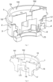
- solid diagrams as shown in Fig.6 to Fig. 10 in order to show the internal structures of components more clearly, these diagrams are all sectioned along the axial direction, with the section cutting planes being represented by blank areas, but these structures are all intact rotary structures in fact.
- Embodiments of the present disclosure provide a quick connection device, a functional arm and a robot, which can realize rapid disassembly and assembly of two components to be connected.
- a locking member when in the locking state, restricts movement of a mounting base towards a direction away from a support base so that a limiting member is in the initial position to restrict movement of a moving assembly in a sleeve, thus the first member to be connected is connected with the second member to be connected; and the locking member, when in the unlocking state, allows movement the mounting base towards the direction away from the support base and releases limiting when the mounting base moves a preset distance towards a direction away from the support base in order to allow the moving assembly to move out of the sleeve, so that the first member to be connected is separated from the second member to be connected.
- Such connection device can realize quick connection and separation of two members to be connected, is easy to operate, and can improve the disassembly and assembly efficiency.
- the present disclosure provides a quick connection device, including a sleeve 5 and a moving assembly A.
- the sleeve 5 is used for connection with the first member to be connected, and the moving assembly A is movably disposed in the sleeve 5 along the axial direction of the sleeve 5.
- the "axial direction”, “radial direction” and “circumferential direction” mentioned herein are all defined based on the sleeve 5.
- the moving assembly A includes a support base 3, a mounting base 1, a locking member 12 and a limiting member.
- the support base 3 is located in the sleeve 5, and the mounting base 1 is used for connection with the second member to be connected, and is movably disposed along the axial direction relative to the support base 3.
- the locking member 12 is fixed to the mounting base 1, and configured to cooperate with the support base 3 to achieve a locking state and an unlocking state and to restrict movement of the mounting base 1 towards a direction away from the support base 3 when in the locking state and allow movement of the mounting base 1 towards a direction away from the support base 3 when in the unlocking state.
- the limiting member is configured to restrict movement of the moving assembly A in the sleeve 5 when the mounting base 1 is in an initial position corresponding to the locking state, so as to realize connection of the first member to be connected and the second member to be connected; and to release limiting when the mounting base 1 moves a preset distance towards the direction away from the support base 3 in order to allow the moving assembly A to move out of the sleeve 5, thus realizing separation of the first member to be connected and the second member to be connected.
- the working principle of this embodiment is as follows: the locking member 12, when in the locking state, restricts movement of the mounting base 1 towards a direction away from the support base 3, so that a limiting member is in the initial position to restrict movement of the moving assembly A in the sleeve 5, thus realizing connection of the first member to be connected and the second member to be connected; and the locking member 12, when in the unlocking state, allows movement the mounting base 1 in the direction away from the support base 3 and releases limiting when the mounting base 1 moves a preset distance in a direction away from the support base 3 in order to allow the moving assembly A to move out of the sleeve 5, thus realizing separation of the first member to be connected and the second member to be connected.
- connection device can realize quick connection and separation of two members to be connected in order to realize detachable connection of the two members to be connected, is easy to operate, can improve the disassembly and assembly efficiency and flexibility in use, and has wide application range.
- the connection device can be used for the detachable connection of two members to be connected in various fields.
- connection device is available for a functional arm
- the first member to be connected includes an arm portion
- the second member to be connected includes a hand portion
- the quick connection device is connected between the arm portion and the hand portion for detachably disposing the hand portion at the wrist end of the arm portion.
- connection device can realize quick connection and separation of the arm portion and the hand portion in order to realize detachable connection of the hand portion and the arm portion, is easy to operate, and can improve the disassembly and assembly efficiency of the hand portion. Moreover, it is easy to replace hand portions of different types and dimensions according to the needs of use.
- the functional arm may be a prosthetic arm for assisting the disabled, and a hand portion of a different dimension can be quickly replaced according to patient's body proportions and life needs, in order to flexibly meet the needs of different patients.
- the functional arm may also be a robot arm of a robot for realizing industrial automation by automatically executing functions.
- the robot arm includes an arm portion and a hand portion.
- the hand portion may be an end effector, such as a mechanical claw or a suck; and the arm portion can position the end effector to a working position required through movement of multiple DOF (degrees of freedom).
- DOF degrees of freedom
- the moving assembly A further includes a travel limiting component, connected to the mounting base 1, and configured to restrict further movement of the mounting base 1 relative to the support base 3 when the mounting base 1 moves outwards a preset distance relative to the sleeve 5, so that the mounting base 1 drives the support base 3 to move outwards together, thereby separating the moving assembly A from the sleeve 5 and in turn realizing separation of the first member to be connected and the second member to be connected.
- the travel limiting component it is possible to move the moving assembly A as a whole outwards relative to the sleeve 5 after the limiting member releases the limiting by outward movement of the mounting base 1.
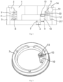
- the support base 3 is provided with a through hole 31 along the axial direction; one end of the mounting base 1 is inserted into the through hole 31; the moving assembly A further includes a blocking ring 4, which is connected to the end of the support base 3 close to the inserted end of the mounting base 1 along the axial direction, i.e., connected to the end of the support base 3 close to the first member to be connected along the axial direction; the inserted end of the mounting base 1 passes through the blocking ring 4 via the through hole 31; and the travel limiting component abuts against the blocking ring 4 when the mounting base 1 moves a preset distance.
- the inserted end of the mounting base 1 is an end located in the sleeve 5.
- the mounting base 1 As one end of the mounting base 1 needs to pass through the through hole 31, after the through hole 31 is disposed on the support base 3, it is easy to enable the travel limiting component to define the moving distance of the mounting base 1 by locally adding the blocking ring 4.
- the travel limiting component includes a connecting rod 7 and a limiting portion 8; a first end of the connecting rod 7 is connected to the inserted end of the mounting base 1, i.e., the bottom end in Fig. 1 ; the limiting portion 8 is connected to a second end of the connecting rod 7; and the length of the connecting rod 7 is configured in such way that the limiting portion 8 abuts against the blocking ring 4 when the mounting base 1 moves the preset distance.
- travel limiting can be performed on the mounting base 1 through a simple and compact structure, with no special limitation to the position relationship of the end face of the inserted end of the mounting base 1 and the end face of the blocking ring 4 away from the end face of the support base 3 along the axial direction, and the preset distance of the mounting base 1 can be defined by the length of the connecting rod 7.
- the moving assembly A further includes a fixed seat 10 and a first fastener 9; the fixed seat 10 is fixed to the inserted end of the mounting base 1 by the first fastener 9; the locking member 12 is disposed in the mounting base 1; and the head of the first fastener 9 protrudes from the end face of the blocking ring 4, for example, the first fastener 9 may employ a blot, a head of which protrudes from the end face of the blocking ring 4 after fixing.
- One or more first fasteners 9 may be disposed along the circumferential direction.
- the travel limiting component includes a limiting ring 15, which is fixed to the mounting base 1, and the outer diameter of the limiting ring 15 is larger than the inner diameter of the blocking ring 4.
- This structure forms a gap between the blocking ring 4 and the limiting ring 15, this gap is configured in such a way that the limiting ring 15 abuts against the blocking ring 4 when the mounting base 1 moves a preset displacement, and the first fastener 9 protruding from the blocking ring 4 needs to be smaller than the gap in dimension. If the dimension of the gap is larger than that of the first fastener 9, a spacing member may be disposed to ensure the dimension of the gap.
- the bolt may be used to fix the fixed seat 10 to the support base 3, and has higher connection strength than a sunk screw.
- the bottom surface of the limiting ring 15 forms a plane, and is easy to place upright on a horizontal table after the moving assembly A is pulled out as a whole, which facilitates adjustment.
- the moving assembly A together with the hand portion can be vertically placed on the horizontal table, which can prevent damage to the hand portion.
- the blocking ring 4 is embedded in the through hole 31, and the side wall of the through hole 31 is provided with an anti-thrust portion 317, configured to restrict the degree of freedom (DOF) of movement of the blocking ring 4 towards the mounting base 1 along the axial direction.
- DOF degree of freedom
- the end face of the blocking ring 4 may be flush with the end face of the support base 3.
- the blocking ring 4 may be fixed to the support base 3 by a second fastener 6.
- the blocking ring 4 is embedded in the through hole 31, which can reduce the axial dimension of the moving assembly A so that the connection device has a more compact structure, and the blocking ring 4 can serve to strengthen the support base 3.
- the mounting base 1 is rotatably disposed relative to the support base 3, so as to switch the locking member 12 between the locking state and the unlocking state by rotation of the mounting base 1 relative to the support base 3.
- the upper edge of the inner side of the sleeve 5 is provided with a raceway 51
- the limiting member includes a plurality of rolling bodies 2, the plurality of rolling bodies 2 are configured to be located between the mounting base 1 and the support base 3 and cooperate with the raceway 51 when in the initial position and completely separate from the raceway 51 when the limiting position is released.
- the mounting base 1 can rotate relative to the support base 3 through the rolling bodies 2 to realize connection and separation of two members to be connected, which can reduce the friction between the mounting base 1 and the support base 3 during the rotation process; and the separation of the moving assembly A and the sleeve 5 can be restricted through the cooperating of the rolling bodies 2 and the raceway 51 when the locking member 12 is in the locking state, which can make the structure design more compact.
- the raceway 51 extends along the circumferential direction to form a ring shape; or the raceway 51 includes a plurality of raceway segments disposed at intervals along the circumferential direction, and each raceway cooperates with at least one rolling body 2.
- the mounting base 1 is provided with a guiding surface 11 configured in such a way that the radial dimension gradually decreases in the direction from the mounting base 1 to the support base 3 to move the rolling bodies 2 inwards along the radial direction when the mounting base 1 moves in a direction away from the support base 3, so as to release limiting to the moving assembly A.
- the guiding surface 11 may be a conical surface, or in an arc shape on the longitudinal section of the sleeve 5, as long as it is capable of guiding the respective rolling bodies 2 to move inwards along the radial direction.
- the mounting base 1 is a rotary part as a whole, including an extension segment 17, a limiting segment 18 and a connection segment 19 connected in sequence along the axial direction.
- the extension segment 17 is inserted into the through hole 31 of the support base 3 and passes through the inner hole of the blocking ring 4.
- the radial dimension of the outer side wall of the limiting segment 18 is larger than that of the outer side wall of the support base 3, so that the limiting segment 18 abuts against the end face of the sleeve 5 to achieve positioning when it is necessary to connect two members to be connected to insert the moving assembly A as a whole into the sleeve 5.
- the connection segment 19 is used for connection with the second member to be connected, such as the hand portion.
- the mounting base 1 is provided with a first cooperating surface 14 connected to the end of the guiding surface 11 having the largest radial dimension
- the support base 3 is provided with a second cooperating surface 33.
- the area of the guiding surface 11 close to the first cooperating surface 14 is configured in such way that the rolling body 2 enter the cavity defined by the first cooperating surface 14, the second cooperating surface and the first guiding surface 11.
- the guiding surface 11 gradually forces the rolling body 2 to move outwards along the radial direction until the rolling bodies 2 are pushed into the raceway 51.
- the guiding surface 11 may be located at the position where the extension segment 17 and the limiting segment 18 are connected.
- the first cooperating surface 14 and/or the second cooperating surface 33 are in an arc structure that cooperate with the rolling body 2, or may also be in a plane structure.
- the end face of the support base 3 close to the mounting base 1 is provided with a plurality of bumps 32, the rolling body 2 is located between two adjacent bumps 32, and the bottom surface of the support base 3 located between the adjacent bumps 32 is provided with the second cooperating surface 33.
- both sides of the bump 32 along the circumferential direction are each provided with an extension portion 321, which may be located at an outermost position on the bump 32 along the radial direction.
- a groove 322 may be disposed on the inner side of the extension portion 321 along the radial direction, so as to enable smooth transition of the side face of the bump 32 along the circumferential direction and the extension portion 321 and provide an effective holding space for the rolling body 2.
- the mounting base 1 is rotatably disposed relative to the support base 3, so as to switch the locking member 12 between the locking state and the unlocking state by rotation of the mounting base 1 relative to the support base 3.
- Such way is easy to operate to achieve unlocking and does not take up extra space during unlocking, and when this way is applied to a functional arm, the hand portion can be conveniently removed by applying a rotational force thereto.
- the support base 3 is provided with a through hole 31 along the axial direction.
- the through hole 31 includes a first hole segment 311; and a second hole segment 312, which has a diameter larger than that of the first hole segment 31 and is located on a side of the first hole segment 311 away from the mounting base 1 along the axial direction.
- a side wall of the second hole segment 312 is provided with a boss 314, a top surface of the boss 314 along the radial direction is radially not lower than an inner wall of the first hole segment 311, and a transition surface 315 is disposed between the boss 314 and the side wall of the second hole segment 312, and may be an arc or a slope or the like.
- the locking member 12 is configured to rotate together with the mounting base 1, lap on the connection surface 313 of the first hole segment 311 and the second hole segment 312 when in the locking state, so as to restrict the outward movement of the mounting base 1 relative to the support base 3, and when being switched from the locking state to the unlocking state, move along the transition surface 315 to abut against the top surface of the boss 314 along the radial direction.
- the locking member 12 may be a pin, a slider or a roller or other structure.
- the end of the locking member 13 may be disposed to be in a ball structure.
- Such structure can realize unlocking of the locking member 12 by the rotation of the mounting base 1.
- the structure is simple, so that stagnation of the locking member 12 is not easy to occur in the case of unlocking, and locking and unlocking can be reliably achieved.
- the side wall of the second hole segment 312 is provided with a boss 314.
- the side wall of the second hole segment 312 is provided with at least two bosses 314, for example, two, three, etc., and the bosses 314 can be evenly distributed along the circumferential direction.
- Such structure can result in that the mounting base 1 is more stable during unlocking by rotation to prevent the mounting base 1 from tilting, so that the unlocking action is more reliable.
- the top surface of the boss 314 along the radial direction is provided with a groove 316, which extends along the axial direction and is running-through in the entire axial direction of the first hole segment 311 and the second hole segment 312, and the bottom surface of the groove 316 along the radial direction is higher than the inner wall of the first hole segment 311.
- the cross section of the groove 316 may be in an arc shape, or the like, and a transition surface is disposed at the joint of the groove 316 and the boss 314.
- the locking member 12 will quickly fall into the groove 316 when moving onto the boss 314 during unlocking, and can be stably kept in the unlocking state to prevent the locking member 12 from re-entering the locking state when the mounting base 1 is moved outwards. Furthermore, in the process of operating by a user, the locking member 12 may make a sound when entering the unlocking state to fall into the groove 316, so that the user can identify the unlocking state.
- the moving assembly A further includes a fixed seat 10, which is connected with the mounting base 1 and provided with a guide slot 102 extending along the radial direction, and the locking member 12 is movably disposed in the guide slot 102.
- the fixed seat 10 includes a seat body 101 and a connecting plate 103 disposed on both sides of the seat body 101 along the circumferential direction, the guide slot 102 is disposed on the seat body 101, and the connecting plate 103 is provided with a hole 104 to fix the fixed seat 10 to the area of the mounting base 1 located at the inserted end by the first fastener 9.
- the number of the fixed seats 10 corresponds to the number of the locking members 12.
- the extension segment 17 of the mounting base 1 serves as the inserted end; a mounting slot 171 is disposed on the end face of the extension segment 17 away from the connection segment 19 along the axial direction, and is running-through along the radial direction of the extension segment 17; and the fixed seat 10 is located in the mounting slot 171 to enable the locking member 12 to contact the side wall of the second hole segment 312 through the running-through mounting slot 171.
- the side wall of the first hole segment 311 is provided with a second guiding surface 32, the radial dimension of which gradually decreases in the direction that the moving assembly A is inserted into the sleeve 5, for example, the second guiding surface 32 may be a slope, allowing the locking member 12 to be gradually pressed back inwards along the radial direction during insertion of the moving assembly A, so as to axially reach a position where the locking member cooperate with the second aperture segment 312.
- the mounting base 1 is provided with a hole at the center thereof, and a boss 16 is disposed on the wall of the hole for mounting a circuit board used to control action of the hand portion or for securing a wire.
- a damping ring is disposed in the sleeve 5 at the inserted end of the moving assembly A; and the damping ring is fixed to the sleeve 5, but is not shown in the figure, and may be disposed at the bottom of the moving assembly A in Fig. 1 .
- a preset compression force is provided between the end face of the inserted end of the moving assembly A and the damping ring, for example, the damping ring is a rigid body, and tightly cooperate with the end face of the inserted end of the moving assembly A; or the damping ring is a resilient member, and has a compression margin with the end face of the inserted end of the moving assembly A.
- the damping ring may be in contact with the blocking ring 4.
- the damping ring when no external force is applied to the second member to be connected, the second member to be connected is kept to be fixed relative to the first member to be connected, and thus can prevent relative rotation of the two members to be connected; and when an external force is applied to the second member to be connected, the position relationship of the two members to be connected can also be adjusted in the circumferential direction.
- the hand portion not subjected to an external force remains fixed to the arm portion to prevent the hand portion from rotating relative to the arm portion so that the hand portion can perform actions stably; and when it is necessary to adjust the circumferential position relationship of the hand portion relative to the arm portion, an external force can be applied to the hand portion for adjustment, and the adjustment is convenient and does not affect normal use.
- the moving assembly A moves towards the direction of the sleeve 5 as a whole.
- the damping ring can stop the movement of the support base 3; continuous application of an external force can cause further movement of the mounting base 1 and various components fixed to the mounting base 1; the locking member 12 slides inwards along the second guiding surface 32; and when sliding to the tail end of the second guiding surface 32, the locking member 12 is pushed out under the action of the reset element 13.
- the movement of the mounting base 1 stops when the limiting segment 18 contacts the sleeve 5, and then the locking member 12 laps on the connection surface 313.
- the rolling body 2 moves outwards along the axial direction under the action of the first guiding surface 14, and the rolling bodies 2 cooperate with the raceway 51 after the mounting base 1 moves to be in position, so as to realize locking of the two members to be connected.
- the moving assembly A further includes a reset element 13, such as a spring, disposed between the fixed seat 10 and the locking member 12 for resetting the locking member 12 when it is automatically switched from the unlocking state to the locking state.
- a reset element 13 such as a spring
- the locking member 12 is a hinge pin, on which an anti-thrust platform is disposed; and the spring can be sleeved on the locking member 12, and abuts against the end of the mounting slot 171 away from the support base 3 in the radial direction and the anti-thrust platform.
- the present disclosure provides a functional arm, including the quick connection device of the embodiments described above, the first member to be connected includes an arm portion, and the second member to be connected includes a hand portion.
- the functional arm includes a robot arm or a prosthetic arm.
- the hand portion includes a wrist portion and a hand back portion
- the connection segment 19 of the mounting base 1 is of a cylindrical structure
- a first hole 191 is disposed on the side wall of the connection segment 19
- the hand back portion is affixed to the outside of the connection segment 19 to fix the hand back portion to the side wall of the connection segment 19 by a third fastener.
- the bottom of the connection segment 19 is partially sealed, and a second hole 192 is formed in the sealed portion, and the wrist portion is inserted into the connection segment 19 and fixed to the inner bottom of the connection segment 19 by a fourth fastener.
- Such connection structure can more firmly fix the hand portion to the mounting base 1.
- the moving assembly A moves towards the direction of the sleeve 5 as a whole, for example, moves downwards in Fig. 1 .
- the support base 3 stops movement due to limiting of the damping ring; continuous application of an external force can cause further movement of the mounting base 1 and various components fixed to the mounting base 1; the locking member 12 slides inwards along the second guiding surface 32; and when sliding to the tail end of the second guiding surface 32, the locking member 12 is pushed out under the action of the reset element 13.
- the movement of the mounting base 1 stops when the limiting segment 18 contacts the sleeve 5, and then the locking member 12 laps on the connection surface 313.
- the rolling bodies 2 move outwards along the radial direction under the action of the first guiding surface 14, and the rolling bodies 2 cooperate with the raceway 51 after the mounting base 1 moves to be in position, so as to realize locking of the hand portion.
- the present disclosure further provides a robot, including the functional arm of the embodiments mentioned above, the functional arm is a robot arm, and the hand portion includes an end effector.
- the robot arm is used for realizing industrial automation through automatically executing required functions.
- the robot arm includes an arm portion and a hand portion.
- the hand portion may be an end effector, such as a mechanical claw or a suck; and the arm portion can position the end effector to a working position required through movement of multiple degrees of freedom. According to functions that the robot needs to execute, the end effector can be replaced quickly and conveniently to meet diversified operational needs of the robot arm and improve the versatility of the robot arm.
Landscapes
- Engineering & Computer Science (AREA)
- Robotics (AREA)
- Mechanical Engineering (AREA)
- Mutual Connection Of Rods And Tubes (AREA)
- Manipulator (AREA)
Claims (15)
- Schnellverbindungsvorrichtung, umfassend eine Buchse (5), die so konfiguriert ist, dass sie mit einem ersten zu verbindenden Element verbunden werden kann und eine bewegliche Anordnung (A), die in der Buchse (5) entlang einer axialen Richtung der Buchse (5) beweglich angeordnet ist, wobei die bewegliche Baugruppe (A) umfasst:eine Stützbasis (3), die in der Buchse (5) angeordnet ist;eine Montagebasis (1), die so konfiguriert ist, dass sie mit einem zweiten zu verbindenden Element verbunden und entlang der axialen Richtung relativ zur Stützbasis (3) beweglich angeordnet ist;ein Verriegelungselement (12), das an der Montagebasis (1) befestigt ist und so konfiguriert ist, dass es mit der Stützbasis (3) zusammenwirkt, zum Erreichen eines Verriegelungszustand und eines Entriegelungszustands, und das so konfiguriert ist, dass es die Bewegung der Montagebasis (1) in eine Richtung weg von der Stützbasis (3) im Verriegelungszustand beschränkt, und so konfiguriert ist, dass es eine Bewegung der Montagebasis (1) in eine Richtung weg von der Stützbasis (3) in dem Entriegelungszustand erlaubt; undein Begrenzungselement, das so konfiguriert ist, dass es die Bewegung der beweglichen Anordnung (A) in der Buchse (5) einschränkt, wenn die Montagebasis (1) in einer dem Verriegelungszustand entsprechenden Ausgangsposition ist, und so konfiguriert ist, die Begrenzung aufzuheben, wenn die Montagebasis (1) konfiguriert ist, sich eine vorgegebene Strecke in Richtung weg von der Stützbasis (3) zu bewegen, um die bewegliche Baugruppe (A) aus der Buchse (5) herausfahren zu lassen.
- Schnellverbindungsvorrichtung nach Anspruch 1, wobei die bewegliche Baugruppe (A) weiterhin aufweisteine Wegbegrenzungskomponente, die mit der Montagebasis (1) verbunden ist, und die Wegbegrenzungskomponente ist so konfiguriert, dass sie die weitere Bewegung der Montagebasis (1) relativ zur Stützbasis (3) begrenzt, wenn die Montagebasis (1) sich eine voreingestellte Strecke bewegt;optional wobei die Stützbasis (3) mit einem Durchgangsloch (31) entlang der axialen Richtung versehen ist; ein Ende der Montagebasis (1) in das Durchgangsloch (31) eingesetzt ist; die bewegliche Baugruppe (A) ferner einen Blockierring (4) aufweist, der mit einem Ende der Stützbasis (3) in der Nähe eines eingesetzten Endes der Montagebasis (1) in axialer Richtung verbunden ist; das eingesetzte Ende der Montagebasis (1) durch den Blockierring (4) über das Durchgangsloch (31) hindurch geht; und das Wegbegrenzungselement an den Blockierring (4) anstößt, wenn die Montagebasis (1) sich um die voreingestellte Strecke bewegt.
- Schnellverbindungsvorrichtung nach Anspruch 2, wobei die
Wegbegrenzungskomponente eine Verbindungsstange (7) und einen Begrenzungsabschnitt (8) umfasst, wobei ein erstes Ende der Verbindungsstange (7) mit dem eingesetzten Ende der Montagebasis (1) verbunden ist, ein zweites Ende der Verbindungsstange (7) mit dem Begrenzungsabschnitt (8) verbunden ist, und eine Länge der Verbindungsstange (7) so konfiguriert ist, dass der Begrenzungsabschnitt (8) an dem Blockierring (4) anliegt, wenn sich die Montagebasis (1) um den vorgegebene Abschnitt bewegt. - Schnellverbindungsvorrichtung nach Anspruch 2, wobei die bewegliche Baugruppe (A) ferner einen festen Sitz (10) und ein erstes Befestigungselement (9) umfasst, wobei der feste Sitz (10) an dem eingesetzten Ende der Montagebasis (1) durch das Befestigungselement (9) befestigt ist, das Verriegelungselement (12) in der Montagebasis (1) angeordnet ist und ein Kopf des ersten Befestigungselementes (9) aus einer Endoberfläche des Blockierrings (4) herausragt;
die Wegbegrenzungskomponente einen Begrenzungsring (15) umfasst, wobei der Begrenzungsring (15) an der Montagebasis (1) befestigt ist und sich an einem Ende des ersten Befestigungselements (9) entfernt von der Montagebasis (1) entlang der axialen Richtung befindet, und zwischen dem Begrenzungsring (15) und dem Blockierring (4) ein Spalt gebildet ist, und so konfiguriert ist, dass der Begrenzungsring (15) an dem Blockierring (4) anstößt, wenn sich die Montagebasis (1) um eine vorgegebene Strecke bewegt. - Schnellverbindungsvorrichtung nach Anspruch 2, wobei der Blockierring (4) in das Durchgangsloch (31) eingebettet und eine Seitenwand des Durchgangslochs (31) mit einem Anti-Stoßabschnitt (317) versehen ist, der so konfiguriert ist, dass er den Freiheitsgrad der Bewegung des Blockierrings (4) in Richtung der Montagebasis (1) entlang der axialen Richtung einschränkt.
- Schnellverbindungsvorrichtung nach Anspruch 1, wobei ein oberer Rand einer Innenseite der Buchse (5) mit einer Laufbahn (51) versehen ist, das Begrenzungselement eine Mehrzahl von Rollkörpern (2) umfasst, die Mehrzahl von Rollkörper (2) so konfiguriert sind, dass sie zwischen der Montagebasis (1) und der Stützbasis (3) angeordnet sind und mit der Laufbahn (51) zusammenwirken, wenn sie sich in der Ausgangsposition befinden und sich vollständig von der Laufbahn (51) trennen, wenn die Begrenzungsposition aufgehoben ist.
- Schnellverbindungsvorrichtung nach Anspruch 6, wobei sich die Laufbahn (51) entlang einer
Umfangsrichtung erstreckt, um eine Ringform zu bilden; oder die Laufbahn (51) eine Vielzahl von Laufbahnsegmenten umfasst, die in Abständen entlang der Umfangsrichtung angeordnet sind, und jede Laufbahn (51) mit mindestens einem Rollkörper (2) zusammenarbeitet. - Schnellverbindungsvorrichtung nach Anspruch 6, wobei der Montagesockel (1) mit einer ersten
Führungsfläche (11) versehen ist, die so konfiguriert ist, dass eine radiale Dimension in Richtung von der Montagebasis (1) zur Stützbasis (3) allmählich abnimmt, so dass sich die Mehrzahl von Rollkörpern (2) entlang der radialen Richtung nach innen bewegen kann, wenn sich die Montagebasis (1) in die Richtung weg von der Stützbasis (3) bewegt;optional die Montagebasis (1) mit einer ersten zusammenwirkenden Oberfläche (14) versehen ist, wobei die erste zusammenwirkende Oberfläche (14) mit einem Ende der ersten Führungsfläche (11) verbunden ist, welches die größte radiale Dimension aufweist, und die Stützbasis (3) mit einer zweiten zusammenwirkenden Fläche (33) versehen ist;in der Ausgangsposition ein Bereich der ersten Führungsfläche (11) nahe der ersten zusammenwirkenden Fläche (14) so konfiguriert ist, dass die Rollkörper (2) in den durch die erste zusammenwirkende Fläche (14), die zweite zusammenwirkende Fläche (33) und die erste Führungsfläche (11) definierten Hohlraum eintreten. - Schnellverbindungsvorrichtung nach Anspruch 1, dadurch gekennzeichnet, dass der Montagesockel (1) relativ zur Stützbasis (3) drehbar angeordnet ist, um das Verriegelungselement (12) zwischen dem Verriegelungszustand und dem Entriegelungszustand durch Drehen der Montagebasis (1) relativ zur Stützbasis (3) zu schalten.
- Schnellverbindungsvorrichtung nach Anspruch 1, wobei die Stützbasis (3) mit einemDurchgangsloch (31) entlang der axialen Richtung versehen ist, wobei dasDurchgangsloch (31) umfasst:ein erstes Lochsegment (311); undein zweites Lochsegment (312), das einen größeren Durchmesser als das erste Lochsegment (311) aufweist und sich auf einer Seite des ersten Lochsegments (311) entfernt von der Montagebasis (1) entlang der axialen Richtung befindet, wobei eine Seitenwand des zweiten Lochsegments (312) mit einem Buckel (314) versehen ist, wobei eine obere Fläche des Buckels (314) entlang der radialen Richtung radial nicht niedriger ist als eine Innenwand des ersten Lochsegments (311) ist, und eine Übergangsfläche (315) zwischen dem Buckel (314) und der Seitenwand des zweiten Lochsegments (312) angeordnet ist;wobei das Verriegelungselement (12) so konfiguriert ist, dass es an einer Verbindungsfläche (313) des ersten Lochsegments (311) und des zweiten Lochsegments (312) schleift, wenn es sich im Verriegelungszustand befindet, und dass es sich entlang der Übergangsfläche (315) bewegt, um gegen eine obere Fläche des Buckels (314) entlang der radialen Richtung anzustoßen, wenn es vom Verriegelungszustand in den Entriegelungszustand umgeschaltet wird.
- Schnellverbindungsvorrichtung nach Anspruch 10, wobei die Oberseite des Buckels (314) in radialer Richtung mit einer Nut (316) versehen ist, die sich entlang der Axialrichtung erstreckt und in einer gesamten axialen Richtung des Durchgangslochs (31) verläuft, und eine Bodenfläche der Nut (316) entlang der radialen Richtung höher ist als die Innenwand des ersten Lochsegments (311).
- Schnellverbindungsvorrichtung nach Anspruch 10, wobei die bewegliche Baugruppe (A) ferner umfasst
einen festen Sitz (10), der mit der Montagebasis (1) verbunden ist, und wobei der feste Sitz (10) mit einem Führungsschlitz (102) versehen ist, der sich entlang der radialen Richtung erstreckt, und das Verriegelungselement (12) beweglich in dem Führungsschlitz (102) angeordnet ist
optional die bewegliche Anordnung (A) weiterhin ein Rückstellelement (13) umfasst, welches zwischen dem Sitz (10) und dem Verriegelungselement (12) angeordnet und so konfiguriert ist, dass es das Verriegelungselement (12) von einem Entriegelungszustand in einen Verriegelungszustand zurückzusetzt. - Schnellverbindungsvorrichtung nach Anspruch 1, ferner umfassend einen Dämpfungsring, der in der Buchse (5) an einem eingesetzten Ende der beweglichen Anordnung (A) angeordnet ist, wobei der Dämpfungsring an der Buchse (5) befestigt ist, und eine Endfläche des eingesetzten Endes der beweglichen Baugruppe (A) mit einer voreingestellte Druckkraft mit dem Dämpfungsring zusammenwirkt, wenn sich das Verriegelungselement (12) in dem Verriegelungszustand befindet.
- Funktionsarm, umfassend die Schnellverbindungsvorrichtung nach einem der Ansprüche 1 bis 13, wobei das erste zu verbindende Element einen Armteil umfasst und das zweite zu verbindende Element ein Handteil umfasst;
optional der Funktionsarm einen Roboterarm oder einen Prothesenarm umfasst. - Roboter, umfassend den Funktionsarm nach Anspruch 14, wobei der Funktionsarm ein Roboterarm ist und der Handteil einen Endeffektor umfasst.
Applications Claiming Priority (2)
| Application Number | Priority Date | Filing Date | Title |
|---|---|---|---|
| CN201911003084.3A CN110614651B (zh) | 2019-10-22 | 2019-10-22 | 快速连接装置、功能臂及机器人 |
| PCT/CN2020/108143 WO2021077858A1 (zh) | 2019-10-22 | 2020-08-10 | 快速连接装置、功能臂及机器人 |
Publications (4)
| Publication Number | Publication Date |
|---|---|
| EP4032664A1 EP4032664A1 (de) | 2022-07-27 |
| EP4032664A4 EP4032664A4 (de) | 2023-10-18 |
| EP4032664B1 true EP4032664B1 (de) | 2024-12-25 |
| EP4032664C0 EP4032664C0 (de) | 2024-12-25 |
Family
ID=68926089
Family Applications (1)
| Application Number | Title | Priority Date | Filing Date |
|---|---|---|---|
| EP20879466.9A Active EP4032664B1 (de) | 2019-10-22 | 2020-08-10 | Schnellverbindungsvorrichtung, funktionsarm und roboter |
Country Status (4)
| Country | Link |
|---|---|
| US (1) | US20220266457A1 (de) |
| EP (1) | EP4032664B1 (de) |
| CN (1) | CN110614651B (de) |
| WO (1) | WO2021077858A1 (de) |
Families Citing this family (11)
| Publication number | Priority date | Publication date | Assignee | Title |
|---|---|---|---|---|
| CN110614651B (zh) * | 2019-10-22 | 2024-09-20 | 京东科技信息技术有限公司 | 快速连接装置、功能臂及机器人 |
| CN111993456A (zh) * | 2020-07-13 | 2020-11-27 | 安徽机电职业技术学院 | 一种方便拆装的机械臂 |
| CN111975704B (zh) * | 2020-08-27 | 2024-07-09 | 清华大学 | 拆装工具 |
| CN112692866B (zh) * | 2021-02-09 | 2022-04-22 | 重庆理工大学 | 快速换装连接装置 |
| CN113400349B (zh) * | 2021-06-02 | 2022-11-25 | 北京思灵机器人科技有限责任公司 | 一种机械臂执行器快换装置 |
| CN114110345B (zh) * | 2021-11-30 | 2024-08-02 | 深圳市中图仪器股份有限公司 | 用于空间坐标测量机的快速装夹装置 |
| CN114851236B (zh) * | 2022-05-16 | 2024-01-12 | 北京京东乾石科技有限公司 | 连接器、端拾器装置及分拣设备 |
| CN117982229B (zh) * | 2022-10-31 | 2024-11-05 | 北京和华瑞博医疗科技有限公司 | 连接装置及手术机器人 |
| CN118046414B (zh) * | 2024-02-19 | 2024-08-20 | 中国科学院空间应用工程与技术中心 | 一种无缆化模块化可重构机械臂系统 |
| CN118161268B (zh) * | 2024-03-13 | 2024-11-19 | 哈尔滨工业大学 | 快换转接机构、模块化手术定位辅助机器人及其操作方法 |
| CN120056166B (zh) * | 2025-04-28 | 2025-08-12 | 浙江强脑科技有限公司 | 腕部快拆装置、机械手和机器人 |
Family Cites Families (18)
| Publication number | Priority date | Publication date | Assignee | Title |
|---|---|---|---|---|
| JP4126074B1 (ja) * | 2007-03-13 | 2008-07-30 | 株式会社スター精機 | ロボットアームカップリング装置 |
| US8992113B2 (en) * | 2009-06-08 | 2015-03-31 | Re2, Inc. | Robust manual connector for robotic arm end effector |
| CN102922534B (zh) * | 2012-10-31 | 2015-09-30 | 广州创研自动化设备有限公司 | 机器人夹具快速更换机构 |
| CN205310300U (zh) * | 2016-01-13 | 2016-06-15 | 绵阳伦奇机器人有限公司 | 一种机器人工具快换器 |
| CN105666512A (zh) * | 2016-04-05 | 2016-06-15 | 山东大学 | 一种机器人末端快速更换装置及更换方法 |
| CN206029925U (zh) * | 2016-08-31 | 2017-03-22 | 湖南瑞森可机器人科技有限公司 | 一种自动更换机器人夹具的快换装置 |
| CN206383153U (zh) * | 2016-12-02 | 2017-08-08 | 江苏尚诚精密模具科技有限公司 | 一种机械手夹具快换机构 |
| CN206263986U (zh) * | 2016-12-13 | 2017-06-20 | 东莞市创丰科技发展有限公司 | 一种机械手快速更换连接结构 |
| CN106863357B (zh) * | 2017-02-27 | 2019-10-01 | 哈尔滨工业大学深圳研究生院 | 一种可重构机械臂的快换接口 |
| CN207044198U (zh) * | 2017-07-07 | 2018-02-27 | 厦门盈硕科智能装备有限公司 | 一种用于工业机器人末端的快速换接装置 |
| CN207273256U (zh) * | 2017-07-20 | 2018-04-27 | 苏州赛腾精密电子股份有限公司 | 锁扣式机械快换接头 |
| CN207206450U (zh) * | 2017-08-22 | 2018-04-10 | 国机智能技术研究院有限公司 | 一种机器人快换装置及末端机构 |
| CN108177158B (zh) * | 2017-12-30 | 2021-08-03 | 哈尔滨工业大学深圳研究生院 | 一种基于记忆合金的可重构机械臂的快换接口 |
| CN109483599B (zh) * | 2018-12-06 | 2024-04-12 | 淮安市博泽科技有限公司 | 电动式机器人末端快换装置 |
| CN110230645B (zh) * | 2019-06-04 | 2024-08-16 | 浙江欣兴工具股份有限公司 | 一种快速连接装置 |
| CN110142799B (zh) * | 2019-06-20 | 2024-04-05 | 苏州大学 | 一种机器人快换关节装置 |
| CN211590180U (zh) * | 2019-10-22 | 2020-09-29 | 北京海益同展信息科技有限公司 | 快速连接装置、功能臂及机器人 |
| CN110614651B (zh) * | 2019-10-22 | 2024-09-20 | 京东科技信息技术有限公司 | 快速连接装置、功能臂及机器人 |
-
2019
- 2019-10-22 CN CN201911003084.3A patent/CN110614651B/zh active Active
-
2020
- 2020-08-10 US US17/770,252 patent/US20220266457A1/en active Pending
- 2020-08-10 EP EP20879466.9A patent/EP4032664B1/de active Active
- 2020-08-10 WO PCT/CN2020/108143 patent/WO2021077858A1/zh not_active Ceased
Also Published As
| Publication number | Publication date |
|---|---|
| EP4032664A4 (de) | 2023-10-18 |
| WO2021077858A1 (zh) | 2021-04-29 |
| CN110614651B (zh) | 2024-09-20 |
| EP4032664C0 (de) | 2024-12-25 |
| CN110614651A (zh) | 2019-12-27 |
| EP4032664A1 (de) | 2022-07-27 |
| US20220266457A1 (en) | 2022-08-25 |
Similar Documents
| Publication | Publication Date | Title |
|---|---|---|
| EP4032664B1 (de) | Schnellverbindungsvorrichtung, funktionsarm und roboter | |
| JP6837466B2 (ja) | 磁性バックル・アセンブリ | |
| US20190162362A1 (en) | Quick locking device | |
| AU2021254603B2 (en) | Connection structure of operation rod | |
| US7097616B2 (en) | Surgical clamp | |
| CN211590180U (zh) | 快速连接装置、功能臂及机器人 | |
| US20130270893A1 (en) | Vehicle wheel hub assembly | |
| WO2017128813A1 (zh) | 夹头 | |
| US20250073608A1 (en) | Compact mobile toy, a connector for a compact mobile toy and kit comprising a compact mobile toy and a connector | |
| CN113585403B (zh) | 一种直杆移动装置和花洒移动架 | |
| CN116533275A (zh) | 机器人手部快换装置及机器人 | |
| CN110769901A (zh) | 用于舞蹈活动竿的末端组件 | |
| CN210240956U (zh) | 用于摄像器材的可拆卸地快速连接装置和摄像器材组件 | |
| CN212027437U (zh) | 一种美发器及其旋转式锁扣结构 | |
| JP2016198216A (ja) | ベッド柵固定装置 | |
| KR101686930B1 (ko) | 원터치 고정기구가 구비된 지지장치 | |
| CN117616208A (zh) | 用于光学设备等、特别是用于电影摄影设备的快速释放联接装置 | |
| CN210118329U (zh) | 快拆扣件 | |
| KR101116290B1 (ko) | 회전 및 직선 운동 장치 | |
| CN221611037U (zh) | 一种三脚架及其云台 | |
| CN116931349A (zh) | 相机兔笼及旋转锁定结构 | |
| CN214947529U (zh) | 一种安装支架及摄像设备 | |
| JP6749821B2 (ja) | フレキシブルロックユニット | |
| CN211947481U (zh) | 送料机构及缝纫机 | |
| CN211325576U (zh) | 手术工具安装装置及手术机器人 |
Legal Events
| Date | Code | Title | Description |
|---|---|---|---|
| STAA | Information on the status of an ep patent application or granted ep patent |
Free format text: STATUS: THE INTERNATIONAL PUBLICATION HAS BEEN MADE |
|
| PUAI | Public reference made under article 153(3) epc to a published international application that has entered the european phase |
Free format text: ORIGINAL CODE: 0009012 |
|
| STAA | Information on the status of an ep patent application or granted ep patent |
Free format text: STATUS: REQUEST FOR EXAMINATION WAS MADE |
|
| 17P | Request for examination filed |
Effective date: 20220419 |
|
| AK | Designated contracting states |
Kind code of ref document: A1 Designated state(s): AL AT BE BG CH CY CZ DE DK EE ES FI FR GB GR HR HU IE IS IT LI LT LU LV MC MK MT NL NO PL PT RO RS SE SI SK SM TR |
|
| DAV | Request for validation of the european patent (deleted) | ||
| DAX | Request for extension of the european patent (deleted) | ||
| A4 | Supplementary search report drawn up and despatched |
Effective date: 20230919 |
|
| RIC1 | Information provided on ipc code assigned before grant |
Ipc: B25J 15/04 20060101ALI20230913BHEP Ipc: B25J 17/00 20060101AFI20230913BHEP |
|
| GRAP | Despatch of communication of intention to grant a patent |
Free format text: ORIGINAL CODE: EPIDOSNIGR1 |
|
| STAA | Information on the status of an ep patent application or granted ep patent |
Free format text: STATUS: GRANT OF PATENT IS INTENDED |
|
| INTG | Intention to grant announced |
Effective date: 20240718 |
|
| GRAS | Grant fee paid |
Free format text: ORIGINAL CODE: EPIDOSNIGR3 |
|
| GRAA | (expected) grant |
Free format text: ORIGINAL CODE: 0009210 |
|
| STAA | Information on the status of an ep patent application or granted ep patent |
Free format text: STATUS: THE PATENT HAS BEEN GRANTED |
|
| AK | Designated contracting states |
Kind code of ref document: B1 Designated state(s): AL AT BE BG CH CY CZ DE DK EE ES FI FR GB GR HR HU IE IS IT LI LT LU LV MC MK MT NL NO PL PT RO RS SE SI SK SM TR |
|
| REG | Reference to a national code |
Ref country code: GB Ref legal event code: FG4D |
|
| REG | Reference to a national code |
Ref country code: CH Ref legal event code: EP |
|
| REG | Reference to a national code |
Ref country code: DE Ref legal event code: R096 Ref document number: 602020043837 Country of ref document: DE |
|
| REG | Reference to a national code |
Ref country code: IE Ref legal event code: FG4D |
|
| U01 | Request for unitary effect filed |
Effective date: 20241225 |
|
| U07 | Unitary effect registered |
Designated state(s): AT BE BG DE DK EE FI FR IT LT LU LV MT NL PT RO SE SI Effective date: 20250113 |
|
| PG25 | Lapsed in a contracting state [announced via postgrant information from national office to epo] |
Ref country code: HR Free format text: LAPSE BECAUSE OF FAILURE TO SUBMIT A TRANSLATION OF THE DESCRIPTION OR TO PAY THE FEE WITHIN THE PRESCRIBED TIME-LIMIT Effective date: 20241225 |
|
| PG25 | Lapsed in a contracting state [announced via postgrant information from national office to epo] |
Ref country code: NO Free format text: LAPSE BECAUSE OF FAILURE TO SUBMIT A TRANSLATION OF THE DESCRIPTION OR TO PAY THE FEE WITHIN THE PRESCRIBED TIME-LIMIT Effective date: 20250325 |
|
| PG25 | Lapsed in a contracting state [announced via postgrant information from national office to epo] |
Ref country code: GR Free format text: LAPSE BECAUSE OF FAILURE TO SUBMIT A TRANSLATION OF THE DESCRIPTION OR TO PAY THE FEE WITHIN THE PRESCRIBED TIME-LIMIT Effective date: 20250326 |
|
| PG25 | Lapsed in a contracting state [announced via postgrant information from national office to epo] |
Ref country code: RS Free format text: LAPSE BECAUSE OF FAILURE TO SUBMIT A TRANSLATION OF THE DESCRIPTION OR TO PAY THE FEE WITHIN THE PRESCRIBED TIME-LIMIT Effective date: 20250325 |
|
| PG25 | Lapsed in a contracting state [announced via postgrant information from national office to epo] |
Ref country code: SM Free format text: LAPSE BECAUSE OF FAILURE TO SUBMIT A TRANSLATION OF THE DESCRIPTION OR TO PAY THE FEE WITHIN THE PRESCRIBED TIME-LIMIT Effective date: 20241225 |
|
| PG25 | Lapsed in a contracting state [announced via postgrant information from national office to epo] |
Ref country code: PL Free format text: LAPSE BECAUSE OF FAILURE TO SUBMIT A TRANSLATION OF THE DESCRIPTION OR TO PAY THE FEE WITHIN THE PRESCRIBED TIME-LIMIT Effective date: 20241225 |
|
| PG25 | Lapsed in a contracting state [announced via postgrant information from national office to epo] |
Ref country code: ES Free format text: LAPSE BECAUSE OF FAILURE TO SUBMIT A TRANSLATION OF THE DESCRIPTION OR TO PAY THE FEE WITHIN THE PRESCRIBED TIME-LIMIT Effective date: 20241225 |
|
| PG25 | Lapsed in a contracting state [announced via postgrant information from national office to epo] |
Ref country code: IS Free format text: LAPSE BECAUSE OF FAILURE TO SUBMIT A TRANSLATION OF THE DESCRIPTION OR TO PAY THE FEE WITHIN THE PRESCRIBED TIME-LIMIT Effective date: 20250425 |
|
| PG25 | Lapsed in a contracting state [announced via postgrant information from national office to epo] |
Ref country code: SK Free format text: LAPSE BECAUSE OF FAILURE TO SUBMIT A TRANSLATION OF THE DESCRIPTION OR TO PAY THE FEE WITHIN THE PRESCRIBED TIME-LIMIT Effective date: 20241225 |
|
| PG25 | Lapsed in a contracting state [announced via postgrant information from national office to epo] |
Ref country code: CZ Free format text: LAPSE BECAUSE OF FAILURE TO SUBMIT A TRANSLATION OF THE DESCRIPTION OR TO PAY THE FEE WITHIN THE PRESCRIBED TIME-LIMIT Effective date: 20241225 |
|
| U20 | Renewal fee for the european patent with unitary effect paid |
Year of fee payment: 6 Effective date: 20250709 |
|
| PLBE | No opposition filed within time limit |
Free format text: ORIGINAL CODE: 0009261 |
|
| STAA | Information on the status of an ep patent application or granted ep patent |
Free format text: STATUS: NO OPPOSITION FILED WITHIN TIME LIMIT |
|
| 26N | No opposition filed |
Effective date: 20250926 |