EP4031439B1 - Hydraulisches ventilmodul für lenk- und arbeitsfunktionen bei einem arbeitsfahrzeug - Google Patents
Hydraulisches ventilmodul für lenk- und arbeitsfunktionen bei einem arbeitsfahrzeug Download PDFInfo
- Publication number
- EP4031439B1 EP4031439B1 EP20780095.4A EP20780095A EP4031439B1 EP 4031439 B1 EP4031439 B1 EP 4031439B1 EP 20780095 A EP20780095 A EP 20780095A EP 4031439 B1 EP4031439 B1 EP 4031439B1
- Authority
- EP
- European Patent Office
- Prior art keywords
- steering
- load sensing
- supply
- hydraulic
- pressure signal
- Prior art date
- Legal status (The legal status is an assumption and is not a legal conclusion. Google has not performed a legal analysis and makes no representation as to the accuracy of the status listed.)
- Active
Links
Images


Classifications
-
- B—PERFORMING OPERATIONS; TRANSPORTING
- B62—LAND VEHICLES FOR TRAVELLING OTHERWISE THAN ON RAILS
- B62D—MOTOR VEHICLES; TRAILERS
- B62D5/00—Power-assisted or power-driven steering
- B62D5/06—Power-assisted or power-driven steering fluid, i.e. using a pressurised fluid for most or all the force required for steering a vehicle
- B62D5/07—Supply of pressurised fluid for steering also supplying other consumers ; control thereof
- B62D5/075—Supply of pressurised fluid for steering also supplying other consumers ; control thereof using priority valves
-
- B—PERFORMING OPERATIONS; TRANSPORTING
- B62—LAND VEHICLES FOR TRAVELLING OTHERWISE THAN ON RAILS
- B62D—MOTOR VEHICLES; TRAILERS
- B62D5/00—Power-assisted or power-driven steering
- B62D5/06—Power-assisted or power-driven steering fluid, i.e. using a pressurised fluid for most or all the force required for steering a vehicle
- B62D5/07—Supply of pressurised fluid for steering also supplying other consumers ; control thereof
-
- B—PERFORMING OPERATIONS; TRANSPORTING
- B62—LAND VEHICLES FOR TRAVELLING OTHERWISE THAN ON RAILS
- B62D—MOTOR VEHICLES; TRAILERS
- B62D12/00—Steering specially adapted for vehicles operating in tandem or having pivotally connected frames
-
- F—MECHANICAL ENGINEERING; LIGHTING; HEATING; WEAPONS; BLASTING
- F15—FLUID-PRESSURE ACTUATORS; HYDRAULICS OR PNEUMATICS IN GENERAL
- F15B—SYSTEMS ACTING BY MEANS OF FLUIDS IN GENERAL; FLUID-PRESSURE ACTUATORS, e.g. SERVOMOTORS; DETAILS OF FLUID-PRESSURE SYSTEMS, NOT OTHERWISE PROVIDED FOR
- F15B11/00—Servomotor systems without provision for follow-up action; Circuits therefor
- F15B11/16—Servomotor systems without provision for follow-up action; Circuits therefor with two or more servomotors
- F15B11/17—Servomotor systems without provision for follow-up action; Circuits therefor with two or more servomotors using two or more pumps
-
- F—MECHANICAL ENGINEERING; LIGHTING; HEATING; WEAPONS; BLASTING
- F15—FLUID-PRESSURE ACTUATORS; HYDRAULICS OR PNEUMATICS IN GENERAL
- F15B—SYSTEMS ACTING BY MEANS OF FLUIDS IN GENERAL; FLUID-PRESSURE ACTUATORS, e.g. SERVOMOTORS; DETAILS OF FLUID-PRESSURE SYSTEMS, NOT OTHERWISE PROVIDED FOR
- F15B13/00—Details of servomotor systems ; Valves for servomotor systems
- F15B13/02—Fluid distribution or supply devices characterised by their adaptation to the control of servomotors
- F15B13/06—Fluid distribution or supply devices characterised by their adaptation to the control of servomotors for use with two or more servomotors
- F15B13/08—Assemblies of units, each for the control of a single servomotor only
- F15B13/0803—Modular units
Definitions
- This disclosure relates to modular valve assemblies for supplying hydraulic pressure to operate steering, work equipment such as a tipping body, and other hydraulic functions of a work vehicle.
- an articulated dump truck with a main valve assembly formed as a unitary valve block with multiple hydraulic circuits for supplying hydraulic pressure to operate the steering, service brakes and cooling fan, and having hydraulic lines to supply pressure to a second valve assembly located elsewhere on the vehicle.
- the second valve assembly is configured to control the tipping body or other work equipment of the vehicle responsive to operator commands received at the second valve block.
- a tipping body or other work equipment of the vehicle will typically be operated when the vehicle is stationary so that the brake and steering functions are not in use, and may require high power or a high flow rate for satisfactory operation when the vehicle is fully loaded. Accordingly, it is known to configure the main valve assembly to combine the supply from both the first and second pumps to power the work equipment via priority valves which prioritise flow to the steering, service brake and fan circuits when required.
- the known main valve assembly protects both steering and service brake and fan circuits against excess demand from the work function circuit, and so makes it possible to combine the flow from both of the first and second pumps to improve operation of the work equipment.
- the valve block is large and complex and is difficult to adapt for use in different vehicles with different equipment specifications.
- Each valve block defines internal flowpaths which open through ports formed in one or more interface surfaces, typically defined by the flat sides of the block.
- US6325170 discloses a modular valve assembly supplied from a hydraulic pump.
- US 2016/0317956 A1 discloses a tracked mining shovel having a modular valve assembly supplying a plurality of hydraulic circuits from a plurality of hydraulic pumps.
- the valve assembly includes filter modules, junction modules for combining the flow via two of the filter modules from two of the pumps, and valve modules operable to direct the flow from the junction modules, selectively to actuate either or both of the bucket and the tracks.
- US2007/0068724 A1 on which the preamble of claim 1 is based, discloses a hydraulic system for a work vehicle including a manifold assembly configured to prioritize hydraulic fluid flow to priority functions over a wide range of engine speeds.
- a hydraulic valve module for use in a vehicle.
- the vehicle includes a plurality of wheels, an equipment for carrying out a work function of the vehicle, a plurality of hydraulic circuits, and first and second hydraulic pumps for supplying hydraulic pressure to the hydraulic circuits.
- the hydraulic circuits include a steering circuit including at least one steering actuator for steering the wheels, and a work function circuit including at least one equipment actuator for operating the equipment.
- the hydraulic valve module includes a plurality of valves, and a monolithic valve block.
- the valve block has a plurality of internal flowpaths, an external, first interface surface, an external, second interface surface, and at least one further external surface.
- the first interface surface is sealingly connectable, in a connected configuration, to a corresponding interface surface of a further, fan and brake function valve module, while the second interface surface is sealingly connectable, in the connected configuration, to a corresponding interface surface of a further, work control valve module.
- the valves are arranged in fluid communication with respective ones of the internal flowpaths to define a work function supply circuit for supplying hydraulic pressure from each of a first pump inlet and a second pump inlet to a work function outlet, and a steering supply circuit for supplying hydraulic pressure from the second pump inlet to a steering supply outlet.
- the first pump inlet opens through the first interface surface to receive a supply of hydraulic pressure from the first pump via the fan and brake function valve module in use in the connected configuration, while the second pump inlet opens through the at least one further external surface to receive a supply of hydraulic pressure from the second pump in use.
- the steering supply outlet opens through the at least one further external surface to supply hydraulic pressure from the steering supply circuit to the steering circuit of the vehicle in use.
- the work function outlet opens through the second interface surface to supply hydraulic pressure from the work function supply circuit via the work control valve module to the work function circuit of the vehicle in use in the connected configuration.
- the plurality of valves include a steering function priority valve, and a fan and brake function priority valve.
- the steering function priority valve is configured to receive a steering load sensing pressure signal from a steering load sensing pressure signal port opening through the at least one further external surface.
- the steering function priority valve is operable responsive to the steering load sensing pressure signal to restrict the supply of hydraulic pressure from the second pump inlet to the work function outlet so as to maintain the supply of hydraulic pressure from the second pump inlet to the steering supply outlet.
- the steering load sensing pressure signal is received in use from the steering circuit of the vehicle.
- the fan and brake function priority valve is configured to receive a fan and brake function load sensing pressure signal from a fan and brake function load sensing pressure signal port that opens through the first interface surface.
- the fan and brake function priority valve is operable responsive to the fan and brake function load sensing pressure signal to restrict the supply of hydraulic pressure from the first pump inlet to the work function outlet so as to maintain hydraulic pressure upstream of the first pump inlet.
- the fan and brake function load sensing pressure signal is received from the fan and brake function valve module in use in the connected configuration.
- an embodiment of the hydraulic valve module is referred to as the steering and work function module 2000.
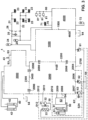
- a vehicle 10 includes a plurality of wheels 20, an equipment 41 for carrying out a work function of the vehicle, a plurality of hydraulic circuits 21, 22, 30, 40, 50, 70, 80, and first and second hydraulic pumps 61, 62, optionally also a third hydraulic pump 63, for supplying hydraulic pressure to the hydraulic circuits.
- the third pump 63 may be driven by a different prime mover from the other pumps, for example, by a motor M.
- a tank or tanks 64 may be arranged to hold the hydraulic fluid.
- the vehicle may further include a cooling fan 31 and other hydraulically actuated equipment as known in the art.
- hydraulic pressure is understood to refer to pressure or both pressure and flow of hydraulic fluid, depending on the application - for example, pressure with little or no flow may be used as a signal to control hydraulic valves, while both pressure and substantial flow may be required to operate the work equipment of the vehicle.
- the hydraulic circuits include a work function circuit 40 and a steering circuit 50, and may further include first and second service brake circuits 21, 22, a fan circuit 30, a parking brake circuit 70 for operating parking brake actuators 71, and a differential lock circuit 80 for operating one or more differential locks 81 in the vehicle transmission.
- Each service brake circuit 21, 22 includes at least one respective service brake actuator 23 for braking the wheels 20, and may also include a respective hydraulic accumulator 24.
- the first and second service brake circuits 21, 22 may be operable by a user control, e.g. a pedal 25, and optionally also by an automatic retarding system 26.
- the vehicle 10 is an articulated truck, and the first and second service brake circuits act respectively on the two front wheels of the tractor unit and the four rear wheels of the trailer unit.
- the fan circuit 30 includes a fan actuator 32 for operating the cooling fan 31, and optionally also a heat exchanger 33 which may be configured as an oil cooler from which heat is extracted to the cooling airflow from the fan.
- the fan 31 may also (or alternatively) extract heat from the coolant circuit of the engine 11 of the vehicle.
- the steering circuit 50 includes at least one steering actuator 51 for steering the wheels 20, for example, responsive to user input via steering controls 52.
- the work function circuit 40 includes at least one equipment actuator 42 for operating the equipment 41.
- the equipment 41 is a tipping body of the vehicle, and the equipment actuator 42 includes one or more hydraulic rams for raising and lowering the tipping body.
- the work equipment could be, for example, a bucket or grab or other operable tool mounted on the vehicle.
- the vehicle may include a work function control signal generator 43 operable by a user to generate a work function control signal S3 to control the equipment.
- the work function control signal may be for example an electrical signal or a hydraulic pressure signal.
- the work function control signal S3 is an electrical signal for raising and lowering the tipping body.
- the vehicle further includes a hydraulic valve assembly 1 formed from a number of hydraulic valve modules 1000, 2000, 3000, 4000 for controlling the hydraulic pressure (which is to say, hydraulic pressure and flow of hydraulic fluid) supplied to the various hydraulic circuits of the vehicle.
- the hydraulic valve modules include a fan and brake function module 1000, a steering and work function module 2000, a work control valve module 3000, and optionally also an auxiliary module 4000.
- Each valve module defines at least one interface surface with multiple ports opening through the interface surface, so that the valve modules can be sealingly connected together with their interface surfaces in abutting relation to place their corresponding ports and internal flowpaths in fluid communication.
- the fan and brake function module 1000 has two external interface surfaces 1100, 1500, and is configured to control a supply of hydraulic pressure to the fan circuit 30 and the service brake circuits 21, 22. Its internal flowpaths are in fluid communication with internal flowpaths of the steering and work function module 2000 via ports formed in interface surface 1100 to communicate with ports 2201, 2202, 2203, 2204, and 2205 of the steering and work function module in the connected configuration, and with internal flowpaths of the auxiliary module 4000 via ports in interface surface 1500.
- the external surfaces of the fan and brake function module 1000 which remain exposed in the connected configuration include an inlet for receiving a supply of hydraulic pressure from the first pump 61, and outlets for supplying hydraulic pressure from the first pump 61 to the first and second service brake circuits 21, 22.
- the fan and brake function module 1000 can be installed for use without the steering and work function module 2000, in which case the fan circuit 30 of the vehicle can be supplied from the respective outlet port in the exposed interface surface 1100.
- the outlet port in the interface surface 1100 to the fan circuit 30 is arranged in fluid communication with an inlet port 2202 and extension flowpath 2028 of the steering and work function module 2000, so that the fan circuit 30 is supplied with hydraulic pressure via the steering and work function module 2000.
- the auxiliary module 4000 is connectable via its external interface surface 4600 to interface surface 1500 of the fan and brake function module 1000.
- the auxiliary module 4000 receives pressure from the first pump 61 via the fan and brake function module 1000 via corresponding ports in the connected interface surfaces 4600, 1500 to supply the parking brake circuit 70 and the differential lock circuit 80 of the vehicle via respective ports formed on the external surface of the auxiliary module 4000.
- Another external port facilitates connection of the parking brake circuit 70 to a hydraulic accumulator 72.
- a further external port is provided for connection to the second service brake circuit 22, which is supplied via a flowpath in the auxiliary module 4000 from the fan and brake function module 1000 via further, intercommunicating ports opening through the interface surfaces 4600, 1500 in the connected configuration as shown.
- the work control module 3000 is configured to receive the work function control signal S3, and includes a work function control valve assembly which is in fluid communication with the work function circuit 40 of the vehicle via ports formed in an external surface of the work control module 3000 that remains exposed in the connected configuration.
- the work function control valve assembly may be operable by a work function pilot pressure supply P1, responsive to the work function control signal S3, to control the pressure supplied to the work function circuit 40 of the vehicle and so to control the operation of the at least one equipment actuator 42.
- the work control module 3000 also includes an external interface surface 3400.
- the internal flowpaths of the work control module 3000 are in fluid communication with internal flowpaths of the steering and work function module 2000 via several ports formed in the external interface surface 3400 to communicate with ports 2301, 2302, 2303, 2304 of the steering and work function module 2000 in the connected configuration.
- the work control module 3000 may be configured to output a work function load sensing pressure signal S2 indicative of variations in load on the work function circuit 40 of the vehicle, as further discussed below.
- the novel hydraulic valve module is exemplified by the steering and work function module 2000, which is shown in Fig. 3 in the connected configuration as part of the valve assembly 1.
- the steering and work function module 2000 includes a plurality of valves 2016, and a monolithic valve block 2099 which has a plurality of internal flowpaths 2013, an external, first interface surface 2200, an external, second interface surface 2300, and at least one further external surface 2700.
- the valves 2016 may be mounted in recesses formed in the valve block, and/or in housings mounted on the valve block, and are fluidly connected together by respective ones of the internal flowpaths.
- the internal flowpaths 2013 may be formed by casting or machining and are indicated generally in the drawings by solid lines for main pressure supply flowpaths, and broken lines for pressure signal flowpaths or return flowpaths to tank.
- the first interface surface 2200 is sealingly connectable, in a connected configuration, to a corresponding interface surface 1100 of the fan and brake function valve module 1000, while the second interface surface 2300 is sealingly connectable, in the connected configuration, to a corresponding interface surface 3400 of the work control valve module 3000.
- the internal flowpaths 2013 communicate with multiple ports formed respectively in each of the first and second interface surfaces 2200, 2300, and in the at least one further external surface 2700 which as shown may extend over more than one external side of the module 2000.
- the ports formed in the interface surfaces 2200, 2300 are arranged in fluid communication with corresponding ports of the corresponding interface surfaces 1100, 3400 of the adjacent valve modules 1000, 3000 so that hydraulic pressure is transmitted through the communicating ports between the valve modules, as discussed in more detail below.
- the steering and work function module 2000 may include connection elements 2098 for sealingly connecting the respective modules together in the connected configuration.
- the connection elements 2098 could comprise for example one or more fixings or fixing receiving portions such as connection holes or connection flanges for receiving screws or other connectors that connect the modules together with their respective interface surfaces sealingly engaged together in the connected configuration, as shown in Fig. 3 .
- the valves 2016 include a steering function priority valve 2020 and a fan and brake function priority valve 2021, and are arranged in fluid communication with respective ones of the internal flowpaths 2013 to define a work function supply circuit 2014 and a steering supply circuit 2015.
- the ports include first and second pump inlets 2205, 2006, a steering supply outlet 2009, a work function outlet 2301, a steering load sensing pressure signal port 2008, and a fan and brake function load sensing pressure signal port 2203.
- the first pump inlet 2205 and the fan and brake function load sensing pressure signal port 2203 open through the first interface surface 2200 to communicate with corresponding ports and internal flowpaths of the fan and brake function module 1000 in the connected configuration.
- the work function outlet 2301 opens through the second interface surface 2300 to supply hydraulic pressure from the work function supply circuit 2014 in the connected configuration, via a corresponding port and internal flowpath of the work control valve module 3000, to the work function control valve assembly of the work control valve module 3000, which in turn supplies pressure to the work function circuit 40 of the vehicle.
- the second pump inlet 2006, the steering supply outlet 2009, and the steering load sensing pressure signal port 2008 open through the at least one further external surface 2700.
- the first pump inlet 2205 receives a supply of hydraulic pressure from the first pump 61 via an internal flowpath of the fan and brake function module 1000 which opens through a corresponding port in the interface surface 1100.
- the second pump inlet 2006 receives a supply of hydraulic pressure from the second pump 62 when the second pump 62 is connected to the inlet 2006 in use.
- the steering supply outlet 2009 is connected to the steering circuit 50 of the vehicle and supplies hydraulic pressure from the steering supply circuit 2015 to the steering circuit 50.
- the pressure is applied to operate the at least one steering actuator 51 responsive to user input via the steering controls 52.
- the work function supply circuit 2014 is configured to control a supply of hydraulic pressure from each of the first and second pumps 61, 62 via the first pump inlet 2205 and the second pump inlet 2006 to the work function outlet 2301.
- the work function supply circuit 2014 includes the steering function priority valve 2020 and the fan and brake function priority valve 2021, and may further include two check valves 2025 through each of which the flow of hydraulic fluid passes from a respective one of the first and second pumps 61, 62.
- the flow from the two pumps is combined downstream of the two check valves, which ensure that each pump supplies only its respective circuits, and then the combined flow is directed to the work function outlet 2301.
- the steering supply circuit 2015 includes the steering function priority valve 2020 and is configured to supply hydraulic pressure from the second pump inlet 2006 to the steering supply outlet 2009.
- the steering circuit 50 is configured to output a steering load sensing pressure signal S4 which indicates load on the steering circuit 50.
- the steering function priority valve 2020 is configured to receive the steering load sensing pressure signal S4 from the steering circuit 50 via the steering load sensing pressure signal port 2008, and is operable responsive to the steering load sensing pressure signal S4 to restrict the supply of hydraulic pressure from the second pump inlet 2006 to the work function outlet 2301 so as to maintain the supply of hydraulic pressure from the second pump inlet 2006 to the steering supply outlet 2009.
- the steering function priority valve 2020 may restrict the supply of hydraulic pressure from the second pump 62 to the work function outlet 2301, so as to maintain the supply of hydraulic pressure from the second pump 62 to the steering supply outlet 2009, responsive to increasing load on the steering circuit 50.
- the fan and brake function valve module 1000 is configured to output a fan and brake function load sensing pressure signal S1 indicative of variations in load on the fan circuit 30 and first and second service brake circuits 21, 22 of the vehicle.
- the fan and brake function load sensing pressure signal S1 is received by the fan and brake function priority valve 2021 via the fan and brake function load sensing pressure signal port 2203 in the connected configuration.
- the fan and brake function priority valve 2021 is operable responsive to the fan and brake function load sensing pressure signal S1 to restrict the supply of hydraulic pressure from the first pump inlet 2205 to the work function outlet 2301 so as to maintain hydraulic pressure upstream of the first pump inlet 2205.
- the fan and brake function priority valve 2021 may restrict the supply of hydraulic pressure from the first pump 61 to the work function outlet 2301, so as to maintain the upstream supply of hydraulic pressure from the first pump 61 via the fan and brake function module 1000 to the first and second service brake circuits 21, 22 and the fan supply circuit 30, responsive to increasing load on any of the fan circuit 30 and the first and second service brake circuits 21, 22.
- the operation of the first and second pumps 61, 62 may be controllable by control pressure signals, for example, to modulate the flow rate from each pump.
- valves 2016 may further include first and second load sensing shuttle valves 2023, 2024.
- the first load sensing shuttle valve 2023 is configured to receive and resolve the fan and brake function load sensing pressure signal S1 from the fan and brake function load sensing pressure signal port 2203, and the work function load sensing pressure signal S2 which is received in the connected configuration from a port opening through the interface surface 3400 of the work function module 3000 via a corresponding work function load sensing pressure signal port 2302 opening through the second interface surface 2300 of the steering and work function module 2000.
- the first load sensing shuttle valve 2023 is configured to produce a first pump control pressure signal S 12 which is applied to a first pump control pressure signal port 2012 opening through the at least one further external surface 2700 and connected to a control system of the first pump 61 to control the first pump 61 in use.
- Signal S 12 may be either respective one of signals S 1 and S2 which is at a higher pressure than the other.
- signal S 12 from valve 2023 controls the first pump 61 responsive to the combined demand from each of the loads that it supplies.
- the second load sensing shuttle valve 2024 is configured to receive and resolve the steering load sensing pressure signal S4 from the steering load sensing pressure signal port 2008, and the work function load sensing pressure signal S2 from the work function load sensing pressure signal port 2302.
- the second load sensing shuttle valve 2024 is configured to produce a second pump control pressure signal S24 which is applied to a second pump control pressure signal port 2010 opening through the at least one further external surface 2700 and connected to a control system of the second pump 62 to control the second pump 62 in use.
- Signal S24 may be either respective one of signals S4 and S2 which is at a higher pressure than the other.
- signal S24 from valve 2024 controls the second pump 62 responsive to the combined demand from each of the loads that it supplies.
- the steering supply outlet 2009 may be arranged in fluid communication with a third pump inlet 2007 which opens through the at least one further external surface 2700 to receive a supply of hydraulic pressure from the third hydraulic pump 63, which is connected in use to the inlet 2007 to provide a secondary supply of hydraulic pressure to the steering circuit 50.
- the steering load sensing pressure signal S4 may be arranged in fluid communication with a third pump control port 2004 opening through the at least one further external surface 2700.
- the third pump 63 may be driven by a motor M.
- the motor M may be controlled by a pressure sensor (not shown) connected to port 2005, which may start the motor M when pressure supplied by the second pump 62 to the steering circuit 50 drops below a threshold pressure value.
- a control system 63' of the third pump 63 may be coupled to the steering load sensing pressure signal S4 via port 2004 to control the output of the third pump 63 while it is in operation.
- pressure supplied by the third pump 63 may be applied to port 2004 which relieves the applied pressure proportionately to the load sensing pressure signal S4.
- the control system 63' may be operable responsive to the remaining, applied pressure upstream of port 2004 which is thus proportionate to the load sensing pressure signal S4.
- the control system 63' may include a bypass valve (not shown) which is operable by the remaining, applied pressure to selectively relieve pressure across the pump 63 so as to adjust its output pressure and flow proportionately to the load sensing pressure signal S4.
- the steering and work function module 2000 may further include a steering load sensing relief valve 2027.
- Valve 2027 is configured to relieve excess pressure from the internal flowpaths carrying the signal S4 to tank 64 via a port 2003 opening through the at least one external surface 2700.
- the work function pilot pressure supply P1 which operates the work function control valve assembly, may be delivered to the work control module 3000 from the steering and work function module 2000 via a pilot pressure supply outlet 2304 which opens through the second interface surface 2300 to communicate with a corresponding port in interface surface 3400.
- the pilot pressure may be supplied to the steering and work function module 2000 from the first pump 61 via the fan and brake function module 1000 in the connected configuration, through a port opening through interface surface 1100 in fluid communication with a pilot pressure supply inlet 2201 opening through the first interface surface 2200.
- the valves 2016 may further include a pilot pressure limit valve 2026 which is configured to limit the pilot pressure received from the pilot pressure supply inlet 2201 and to supply the limited pilot pressure P1 to the pilot pressure supply outlet 2304.
- the pilot pressure limit valve 2026 may be arranged in fluid communication with a drain flowpath 2022 of the steering and work function module 2000, which is arranged in the connected configuration to relieve hydraulic pressure from internal drain flowpaths of the work control valve module 3000 via the fan and brake function valve module 1000 to tank 64.
- the drain flowpath 2022 opens through a drain inlet 2303 in the second interface surface 2300 and a drain outlet 2204 in the first interface surface 2200.
- the drain inlet 2303 communicates with internal drain flowpaths of the work control module 3000, while the drain outlet 2204 communicates with a corresponding port in the interface surface 1100 of the fan and brake function module 1000 which in turn communicates with an outlet to tank 64.
- the internal flowpaths 2013 of the steering and work function module 2000 may include an extension flowpath 2028.
- the extension flowpath 2028 opens through an extension inlet 2202 in the first interface surface 2200 and an extension outlet 2011 in the at least one further external surface 2700 so that the extension inlet 2202 is in uninterrupted fluid communication with the extension outlet 2011 via the extension flowpath 2028. That is to say, the extension flowpath 2028 does not contain any valves or other obstructions to prevent hydraulic fluid from flowing freely in any direction through the extension flowpath 2028 between the extension inlet 2202 and the extension outlet 2011.
- the function of the fan and brake function module 1000 in controlling the supply of pressure to the fan circuit 30 is unaffected by the presence of the steering and work function module 2000 in the connected configuration.
- Additional ports 2001, 2002, 2005 may be provided in the at least one external surface 2700 for connection of pressure sensors.
- Various test ports 90 may be provided.
- the steering and work function module 2000 is configured to receive a supply of hydraulic pressure, both from the first pump 61 via port 2205 in the first interface surface 2200 when connected to the fan and brake function module 1000, and from the second pump 62 via port 2006 in the external surface 2700.
- the module combines both flows to supply the work function circuit 40 of the vehicle via port 2301 in the second interface surface 2300 when connected to the work control module 3000.
- the module further prioritises flow from the second pump 62 to the steering supply outlet 2009 over the work function outlet 2301.
- the module 2000 restricts flow from the first pump inlet 2205 to the work function outlet 2301 so as to prioritise and maintain pressure upstream of the first pump inlet 2205. This protects the hydraulic circuits of the connected, fan and brake function module 1000, which may supply service brake and cooling fan circuits of the vehicle 10.
- the novel module also referred to and exemplified in the above described embodiment as the steering and work function module 2000, may be used as part of a modular valve assembly to provide optimal use of the pump capacity to supply work equipment that requires a combined flow when installed in a work vehicle with more than one pump.
- the novel module ensures that the steering circuit and upstream brake and fan circuits are protected when combined flow is supplied to the work function circuit, while accommodating alternative valve configurations for the other, upstream and downstream elements by suitable adaptation of the other modules of the assembly.
- the valve assembly can be adapted to the requirements of different vehicles while ensuring that circuit priorities are always respected.
- the novel module can further include shuttle valves for supplying control pressure signals to the pumps, thus combining together the circuit prioritisation and pump control functions of a complex valve assembly into a single module. Since pump control governs the supply of pressure and circuit prioritisation governs the availability of the supplied pressure to critical circuits, this further ensures that pressure is available to the critical circuits of the vehicle even in alternative configurations of the modular assembly.
- modules of the valve assembly may be used on their own in vehicles with different specifications requiring less than all of the modules.
- the fan and brake function module 1000 may be used on its own or in combination with the auxiliary module 4000 to supply hydraulic pressure from the first pump inlet to the fan and service brake circuits, optionally also the parking brake and differential lock actuator circuits, of a vehicle that does not require a supply to steering and work function circuits.
Landscapes
- Engineering & Computer Science (AREA)
- Mechanical Engineering (AREA)
- Chemical & Material Sciences (AREA)
- Combustion & Propulsion (AREA)
- Transportation (AREA)
- Physics & Mathematics (AREA)
- Fluid Mechanics (AREA)
- General Engineering & Computer Science (AREA)
- Power Steering Mechanism (AREA)
- Valves And Accessory Devices For Braking Systems (AREA)
Claims (6)
- Hydraulikventilmodul (2000) zur Verwendung in einem Fahrzeug (10), wobei das Fahrzeug (10) einschließt:eine Vielzahl von Rädern (20),eine Einrichtung (41) zum Ausführen einer Arbeitsfunktion des Fahrzeugs, eine Vielzahl von Hydraulikschaltungen (40, 50) undeine erste und eine zweite Hydraulikpumpe (61, 62) zum Zuführen von Hydraulikdruck zu den Hydraulikschaltungen;wobei die Hydraulikschaltungen einschließen:eine Lenkschaltung (50), die mindestens einen Lenkaktuator (51) zum Lenken der Räder (20) einschließt, undeine Arbeitsfunktionsschaltung (40), die mindestens einen Einrichtungsaktuator (42) zum Betreiben der Einrichtung (41) einschließt;wobei das Hydraulikventilmodul (2000) einschließt:eine Vielzahl von Ventilen (2016), undeinen monolithischen Ventilblock (2099);wobei die Vielzahl von Ventilen (2016) ein Lenkfunktionsprioritätsventil (2020) einschließt, das konfiguriert ist, um ein Lenklasterfassungsdrucksignal (S4) zu empfangen, wobei das Lenklasterfassungsdrucksignal (S4) während der Verwendung von der Lenkschaltung (50) des Fahrzeugs (10) empfangen wird;wobei der Ventilblock (2099) in einer verbundenen Konfiguration mit einem weiteren Arbeitssteuerventilmodul (3000) verbindbar ist und eine Vielzahl von internen Strömungswegen (2013) aufweist;dadurch gekennzeichnet, dass:der Ventilblock (2099) einschließt:eine externe, erste Schnittstellenoberfläche (2200),eine externe, zweite Schnittstellenoberfläche (2300) undmindestens eine weitere Außenoberfläche (2700);wobei die erste Schnittstellenoberfläche (2200) in der verbundenen Konfiguration mit einer entsprechenden Schnittstellenoberfläche (1100) eines weiteren Lüfter- und Bremsfunktionsventilmoduls (1000) dichtend verbindbar ist;wobei die zweite Schnittstellenoberfläche (2300) in der verbundenen Konfiguration mit einer entsprechenden Schnittstellenoberfläche (3400) des Arbeitssteuerungsventilmoduls (3000) dichtend verbindbar ist;wobei die Ventile in Fluidverbindung mit jeweiligen der internen Strömungswege (2013) angeordnet sind, um zu definieren:eine Arbeitsfunktionszufuhrschaltung (2014) zum Zuführen von Hydraulikdruck von jedem von einem ersten Pumpeneinlass (2205) und einem zweiten Pumpeneinlass (2006) zu einem Arbeitsfunktionsauslass (2301) undeine Lenkzufuhrschaltung (2015) zum Zuführen von Hydraulikdruck von dem zweiten Pumpeneinlass (2006) zu einem Lenkzufuhrauslass (2009);wobei sich der erste Pumpeneinlass (2205) durch die erste Schnittstellenoberfläche (2200) öffnet, um eine Zufuhr von Hydraulikdruck von der ersten Pumpe (61) über das Lüfter- und Bremsfunktionsventilmodul (1000) bei Verwendung in der verbundenen Konfiguration zu empfangen;wobei sich der zweite Pumpeneinlass (2006) durch die mindestens eine weitere Außenoberfläche (2700) öffnet, um während der Verwendung eine Zufuhr von Hydraulikdruck von der zweiten Pumpe (62) zu empfangen;wobei sich der Lenkzufuhrauslass (2009) durch die mindestens eine weitere Außenoberfläche (2700) öffnet, um während der Verwendung Hydraulikdruck von der Lenkzufuhrschaltung (2015) zu der Lenkschaltung (50) des Fahrzeugs zuzuführen;wobei sich der Arbeitsfunktionsauslass (2301) durch die zweite Schnittstellenoberfläche (2300) öffnet, um während der Verwendung Hydraulikdruck von der Arbeitsfunktionszufuhrschaltung (2014) über das Arbeitssteuerventilmodul (3000) zu der Arbeitsfunktionsschaltung (40) des Fahrzeugs in der verbundenen Konfiguration zuzuführen;wobei das Lenkfunktionsprioritätsventil (2020) konfiguriert ist, um das Lenklasterfassungsdrucksignal (S4) von einem Lenklasterfassungsdrucksignalanschluss (2008), der sich durch die mindestens eine weitere Außenoberfläche (2700) öffnet, zu empfangen, und als Reaktion auf das Lenklasterfassungsdrucksignal (S4) betätigbar ist, um die Zufuhr von Hydraulikdruck von dem zweiten Pumpeneinlass (2006) zu dem Arbeitsfunktionsauslass (2301) durch die Arbeitsfunktionszufuhrschaltung (2014) zu beschränken, um die Zufuhr von Hydraulikdruck von dem zweiten Pumpeneinlass (2006) zu dem Lenkzufuhrauslass (2009) durch die Lenkzufuhrschaltung (2015) aufrechtzuerhalten; unddie Vielzahl von Ventilen ferner ein Lüfter- und Bremsfunktionsprioritätsventil (2021) einschließt, das konfiguriert ist, um ein Lüfter- und Bremsfunktionslasterfassungsdrucksignal (S1) von einem Lüfter- und Bremsfunktionslasterfassungsdrucksignalanschluss (2203) zu empfangen, der sich durch die erste Schnittstellenoberfläche (2200) öffnet, und als Reaktion auf das Lüfter- und Bremsfunktionslasterfassungsdrucksignal (S1) betätigbar ist, um die Zufuhr von Hydraulikdruck von dem ersten Pumpeneinlass (2205) zu dem Arbeitsfunktionsauslass (2301) durch die Arbeitsfunktionszufuhrschaltung (2014) zu beschränken, um den Hydraulikdruck stromaufwärts des ersten Pumpeneinlasses (2205) aufrechtzuerhalten; wobei das Lüfter- und Bremsfunktionslasterfassungsdrucksignal (S1) von dem Lüfter- und Bremsfunktionsventilmodul (1000) während der Verwendung in der verbundenen Konfiguration empfangen wird.
- Hydraulikventilmodul (2000) nach Anspruch 1, wobei die Vielzahl von Ventilen (2016) ferner einschließt:ein erstes Lasterfassungswechselventil (2023), das konfiguriert ist zum:Empfangen und Auflösen des Lüfter- und Bremsfunktionslasterfassungsdrucksignals (S1) und eines Arbeitsfunktionslasterfassungsdrucksignals (S2) aus einem Arbeitsfunktionslasterfassungsdrucksignalanschluss (2302), der sich durch die zweite Schnittstellenoberfläche (2300) öffnet, undbasierend auf dem Lüfter- und Bremsfunktionslasterfassungsdrucksignal (S1) und dem Arbeitsfunktionslasterfassungsdrucksignal (S2), Erzeugen eines ersten Pumpensteuerdrucksignals (S12) an einem ersten Pumpensteuerdrucksignalanschluss (2012), der sich durch die mindestens eine weitere Außenoberfläche (2700) öffnet, zum Steuern der ersten Pumpe (61) während der Verwendung; undein zweites Lasterfassungswechselventil (2024), das konfiguriert ist zum:Empfangen und Auflösen des Lenklasterfassungsdrucksignals (S4) und des Arbeitsfunktionslasterfassungsdrucksignals (S2) undbasierend auf dem Lenklasterfassungsdrucksignal (S4) und dem Arbeitsfunktionslasterfassungsdrucksignal (S2), Erzeugen eines zweiten Pumpensteuerdrucksignals (S24) an einem zweiten Pumpensteuerdrucksignalanschluss (2010), der sich durch die mindestens eine weitere Außenoberfläche (2700) öffnet, zum Steuern der zweiten Pumpe (62) während der Verwendung.
- Hydraulikventilmodul (2000) nach Anspruch 1, wobei der Lenkzufuhrauslass (2009) in Fluidverbindung mit einem dritten Pumpeneinlass (2007) angeordnet ist, wobei sich der dritte Pumpeneinlass (2007) durch die mindestens eine weitere Außenoberfläche (2700) öffnet, um während der Verwendung eine Zufuhr von Hydraulikdruck von einer dritten Hydraulikpumpe (63) des Fahrzeugs (10) zu empfangen; und
das Lenklasterfassungsdrucksignal (S4) in Fluidverbindung mit einem dritten Pumpensteueranschluss (2004) angeordnet ist, der sich durch die mindestens eine weitere Außenoberfläche (2700) öffnet, um den Betrieb der dritten Pumpe (63) während der Verwendung zu steuern. - Hydraulikventilmodul (2000) nach Anspruch 1, wobei die Vielzahl von Ventilen (2016) ferner ein Vorsteuerdruckbegrenzungsventil (2026) einschließt, das konfiguriert ist, um Vorsteuerdruck, der von einem Vorsteuerdruckzufuhreinlass (2201) empfangen wird, der sich durch die erste Schnittstellenoberfläche (2200) öffnet, zu begrenzen, und einen Vorsteuerdruck (P1) einem Vorsteuerdruckzufuhrauslass (2304) zuzuführen, der sich durch die zweite Schnittstellenoberfläche (2300) öffnet.
- Hydraulikventilmodul (2000) nach Anspruch 4, wobei das Vorsteuerdruckbegrenzungsventil (2026) in Fluidverbindung mit einem Abflussströmungsweg (2022) zwischen einem Abflusseinlass (2303) in der zweiten Schnittstellenoberfläche (2300) und einem Abflussauslass (2204) in der ersten Schnittstellenoberfläche (2200) angeordnet ist, um Hydraulikdruck vom Arbeitssteuerventilmodul (3000) über das Lüfter- und Bremsfunktionsventilmodul (1000) zu Tank (64) während der Verwendung in der verbundenen Konfiguration zu entlasten.
- Hydraulikventilmodul (2000) nach Anspruch 1, wobei die inneren Strömungswege (2013) einen Verlängerungsströmungsweg (2028) einschließen, wobei sich der Verlängerungsströmungsweg (2028) durch einen Verlängerungseinlass (2202) in der ersten Schnittstellenoberfläche (2200) und einen Verlängerungsauslass (2011) in der mindestens einen weiteren Außenoberfläche (2700) öffnet, wobei der Verlängerungseinlass (2202) über den Verlängerungsströmungsweg (2028) mit dem Verlängerungsauslass (2011) in ununterbrochener Fluidverbindung steht.
Applications Claiming Priority (2)
| Application Number | Priority Date | Filing Date | Title |
|---|---|---|---|
| US16/574,124 US10822025B1 (en) | 2019-09-18 | 2019-09-18 | Hydraulic valve module for steering and work functions in a work vehicle |
| PCT/EP2020/025410 WO2021052623A1 (en) | 2019-09-18 | 2020-09-11 | Hydraulic valve module for steering and work functions in a work vehicle |
Publications (2)
| Publication Number | Publication Date |
|---|---|
| EP4031439A1 EP4031439A1 (de) | 2022-07-27 |
| EP4031439B1 true EP4031439B1 (de) | 2023-07-19 |
Family
ID=72644186
Family Applications (1)
| Application Number | Title | Priority Date | Filing Date |
|---|---|---|---|
| EP20780095.4A Active EP4031439B1 (de) | 2019-09-18 | 2020-09-11 | Hydraulisches ventilmodul für lenk- und arbeitsfunktionen bei einem arbeitsfahrzeug |
Country Status (4)
| Country | Link |
|---|---|
| US (1) | US10822025B1 (de) |
| EP (1) | EP4031439B1 (de) |
| CN (1) | CN114423669B (de) |
| WO (1) | WO2021052623A1 (de) |
Families Citing this family (2)
| Publication number | Priority date | Publication date | Assignee | Title |
|---|---|---|---|---|
| GB202019738D0 (en) | 2020-12-15 | 2021-01-27 | Agco Int Gmbh | Pressurised Fluid Supply System for An Agricultural Vehicle |
| GB2612850B (en) * | 2021-11-16 | 2024-04-10 | Caterpillar Sarl | Estimating hydraulic flow in a steering system of an articulated vehicle |
Family Cites Families (24)
| Publication number | Priority date | Publication date | Assignee | Title |
|---|---|---|---|---|
| US5050696A (en) * | 1988-10-20 | 1991-09-24 | Deere & Company | Secondary hydraulic steering system |
| RU1782838C (ru) | 1989-05-23 | 1992-12-23 | Камское объединение по производству большегрузных автомобилей | Объединенна гидравлическа система рулевого управлени и дополнительного оборудовани транспортного средства |
| DE19750367C2 (de) | 1997-11-14 | 2001-07-05 | Danfoss Fluid Power As Nordbor | Hydraulischer Fahrzeugantrieb und Ventilmodul hierfür |
| US6422121B1 (en) * | 2000-05-25 | 2002-07-23 | Finn Corporation | Hydraulic system |
| US6931847B1 (en) * | 2004-03-04 | 2005-08-23 | Sauer-Danfoss, Inc. | Flow sharing priority circuit for open circuit systems with several actuators per pump |
| US7597168B2 (en) * | 2005-09-23 | 2009-10-06 | Deere & Company | Low engine speed steering performance |
| JP2008162410A (ja) | 2006-12-28 | 2008-07-17 | Komatsu Ltd | 作業車両のステアリングおよび作業機の制御装置 |
| KR101446803B1 (ko) * | 2007-12-24 | 2014-10-02 | 두산인프라코어 주식회사 | 건설 기계의 유압회로 |
| US8756930B2 (en) * | 2010-05-28 | 2014-06-24 | Caterpillar Inc. | Hydraulic system having implement and steering flow sharing |
| CN102030035B (zh) | 2010-12-06 | 2012-09-26 | 徐州重型机械有限公司 | 九轴汽车底盘起重机及其转向控制系统、方法 |
| CN102384113B (zh) * | 2011-08-09 | 2014-10-29 | 三一矿机有限公司 | 一种矿用自卸车供油节能装置 |
| JP2013248928A (ja) | 2012-05-30 | 2013-12-12 | Komatsu Ltd | 無人ダンプトラック |
| DE102013209569A1 (de) * | 2012-05-31 | 2013-12-05 | GM Global Technology Operations LLC (n. d. Gesetzen des Staates Delaware) | Haltekupplungsventil-steuersystem |
| US9239085B2 (en) * | 2012-08-03 | 2016-01-19 | Caterpillar Inc. | Reduced parasitic hydraulic fan system with reversing capability |
| JP6013888B2 (ja) | 2012-11-20 | 2016-10-25 | 株式会社Kcm | 液圧駆動システム、及びそれを備える建設機械 |
| CN203806708U (zh) * | 2014-05-02 | 2014-09-03 | 襄阳忠良工程机械有限责任公司 | 移动式装卸机 |
| DK3009689T3 (da) * | 2014-10-15 | 2021-07-05 | Danfoss Power Solutions Aps | Et køretøjs hydrauliske system |
| EP3212446B1 (de) * | 2014-10-27 | 2022-05-11 | Danfoss Power Solutions II Technology A/S | Hydraulischer hybrider antriebsschaltkreis mit hydrostatischer option und verfahren zum antreiben einer zubehörfunktion eines hydraulischen systems einer mobilen arbeitsmaschine |
| WO2016085959A1 (en) * | 2014-11-24 | 2016-06-02 | Parker-Hannifin Corporation | System architectures for steering and work functions in a wheel loader |
| CN105986595B (zh) * | 2015-02-04 | 2019-10-01 | 卡特彼勒(青州)有限公司 | 用于机器的液压系统及机器 |
| US20160317956A1 (en) | 2015-05-01 | 2016-11-03 | Caterpillar Global Mining Llc | Combination manifold for a machine |
| CN105114165B (zh) * | 2015-07-27 | 2017-10-03 | 广西柳工机械股份有限公司 | 矿用自卸车散热系统 |
| CN204985136U (zh) | 2015-08-26 | 2016-01-20 | 徐工集团工程机械股份有限公司科技分公司 | 一种卸荷阀块、开闭芯液压系统及工程机械 |
| CN105134678A (zh) | 2015-08-26 | 2015-12-09 | 徐工集团工程机械股份有限公司科技分公司 | 先导控制阀块、开闭芯液压系统及工程机械 |
-
2019
- 2019-09-18 US US16/574,124 patent/US10822025B1/en active Active
-
2020
- 2020-09-11 CN CN202080065403.8A patent/CN114423669B/zh active Active
- 2020-09-11 WO PCT/EP2020/025410 patent/WO2021052623A1/en not_active Ceased
- 2020-09-11 EP EP20780095.4A patent/EP4031439B1/de active Active
Also Published As
| Publication number | Publication date |
|---|---|
| CN114423669B (zh) | 2023-09-08 |
| US10822025B1 (en) | 2020-11-03 |
| EP4031439A1 (de) | 2022-07-27 |
| CN114423669A (zh) | 2022-04-29 |
| WO2021052623A1 (en) | 2021-03-25 |
Similar Documents
| Publication | Publication Date | Title |
|---|---|---|
| EP4031422B1 (de) | Modulare hydraulische anordnung für arbeitsfahrzeug | |
| US6848255B2 (en) | Hydraulic fan drive system | |
| US5615553A (en) | Hydraulic circuit with load sensing feature | |
| US4321793A (en) | Integrated hydraulic circuit for off highway work vehicles | |
| EP4031421B1 (de) | Hydraulikventilmodul und verfahren zur versorgung des hydraulikdrucks an schaltungen eines fahrzeugs | |
| EP4031439B1 (de) | Hydraulisches ventilmodul für lenk- und arbeitsfunktionen bei einem arbeitsfahrzeug | |
| EP3201475B1 (de) | Mehrwegeventil | |
| US4517800A (en) | Hydraulic control system for off-highway self-propelled work machines | |
| US20130312401A1 (en) | Pilot Pressure Supply System | |
| US11614102B2 (en) | Pressure supply device | |
| US4559965A (en) | Multiple compensating unloading valve circuit | |
| SE529871C2 (sv) | Ventilblock, redskapsfäste och arbetsmaskin, samt användning av ett ventilblock | |
| US4633666A (en) | Integrated hydraulic system | |
| US6460655B2 (en) | Vehicle hydraulic system | |
| US20060196179A1 (en) | Load-sensing integrated brake and fan hydraulic system | |
| US7694776B2 (en) | Hydraulic steering system with protection against uncontrolled steering movements | |
| CA1324179C (en) | Three-channel adaptive braking system | |
| GB2465572A (en) | Switchable source hydraulic supply system | |
| JP2006505750A (ja) | 油圧式デュアルサーキットシステム | |
| EP0051603B1 (de) | Serien-parallel-wähler für lenkung und arbeitswerkzeug | |
| EP1355067B1 (de) | Lastdruckunabhängiges, hydraulisches System | |
| SU1665118A1 (ru) | Гидросистема | |
| CA1141265A (en) | Controlled pressure upstaging and flow reduction | |
| CA1044993A (en) | Hydraulic system with dual pumps for tractor brake, steering, and loader valves | |
| JPH0712245B2 (ja) | トラクタの油圧回路 |
Legal Events
| Date | Code | Title | Description |
|---|---|---|---|
| STAA | Information on the status of an ep patent application or granted ep patent |
Free format text: STATUS: UNKNOWN |
|
| STAA | Information on the status of an ep patent application or granted ep patent |
Free format text: STATUS: THE INTERNATIONAL PUBLICATION HAS BEEN MADE |
|
| PUAI | Public reference made under article 153(3) epc to a published international application that has entered the european phase |
Free format text: ORIGINAL CODE: 0009012 |
|
| STAA | Information on the status of an ep patent application or granted ep patent |
Free format text: STATUS: REQUEST FOR EXAMINATION WAS MADE |
|
| 17P | Request for examination filed |
Effective date: 20220329 |
|
| AK | Designated contracting states |
Kind code of ref document: A1 Designated state(s): AL AT BE BG CH CY CZ DE DK EE ES FI FR GB GR HR HU IE IS IT LI LT LU LV MC MK MT NL NO PL PT RO RS SE SI SK SM TR |
|
| DAV | Request for validation of the european patent (deleted) | ||
| DAX | Request for extension of the european patent (deleted) | ||
| GRAP | Despatch of communication of intention to grant a patent |
Free format text: ORIGINAL CODE: EPIDOSNIGR1 |
|
| STAA | Information on the status of an ep patent application or granted ep patent |
Free format text: STATUS: GRANT OF PATENT IS INTENDED |
|
| INTG | Intention to grant announced |
Effective date: 20230214 |
|
| GRAS | Grant fee paid |
Free format text: ORIGINAL CODE: EPIDOSNIGR3 |
|
| GRAA | (expected) grant |
Free format text: ORIGINAL CODE: 0009210 |
|
| STAA | Information on the status of an ep patent application or granted ep patent |
Free format text: STATUS: THE PATENT HAS BEEN GRANTED |
|
| AK | Designated contracting states |
Kind code of ref document: B1 Designated state(s): AL AT BE BG CH CY CZ DE DK EE ES FI FR GB GR HR HU IE IS IT LI LT LU LV MC MK MT NL NO PL PT RO RS SE SI SK SM TR |
|
| P01 | Opt-out of the competence of the unified patent court (upc) registered |
Effective date: 20230614 |
|
| REG | Reference to a national code |
Ref country code: GB Ref legal event code: FG4D |
|
| REG | Reference to a national code |
Ref country code: CH Ref legal event code: EP |
|
| REG | Reference to a national code |
Ref country code: DE Ref legal event code: R096 Ref document number: 602020014158 Country of ref document: DE |
|
| REG | Reference to a national code |
Ref country code: IE Ref legal event code: FG4D |
|
| REG | Reference to a national code |
Ref country code: SE Ref legal event code: TRGR |
|
| REG | Reference to a national code |
Ref country code: LT Ref legal event code: MG9D |
|
| REG | Reference to a national code |
Ref country code: NL Ref legal event code: MP Effective date: 20230719 |
|
| REG | Reference to a national code |
Ref country code: AT Ref legal event code: MK05 Ref document number: 1589204 Country of ref document: AT Kind code of ref document: T Effective date: 20230719 |
|
| PG25 | Lapsed in a contracting state [announced via postgrant information from national office to epo] |
Ref country code: NL Free format text: LAPSE BECAUSE OF FAILURE TO SUBMIT A TRANSLATION OF THE DESCRIPTION OR TO PAY THE FEE WITHIN THE PRESCRIBED TIME-LIMIT Effective date: 20230719 |
|
| PG25 | Lapsed in a contracting state [announced via postgrant information from national office to epo] |
Ref country code: GR Free format text: LAPSE BECAUSE OF FAILURE TO SUBMIT A TRANSLATION OF THE DESCRIPTION OR TO PAY THE FEE WITHIN THE PRESCRIBED TIME-LIMIT Effective date: 20231020 |
|
| PG25 | Lapsed in a contracting state [announced via postgrant information from national office to epo] |
Ref country code: IS Free format text: LAPSE BECAUSE OF FAILURE TO SUBMIT A TRANSLATION OF THE DESCRIPTION OR TO PAY THE FEE WITHIN THE PRESCRIBED TIME-LIMIT Effective date: 20231119 |
|
| PG25 | Lapsed in a contracting state [announced via postgrant information from national office to epo] |
Ref country code: RS Free format text: LAPSE BECAUSE OF FAILURE TO SUBMIT A TRANSLATION OF THE DESCRIPTION OR TO PAY THE FEE WITHIN THE PRESCRIBED TIME-LIMIT Effective date: 20230719 Ref country code: PT Free format text: LAPSE BECAUSE OF FAILURE TO SUBMIT A TRANSLATION OF THE DESCRIPTION OR TO PAY THE FEE WITHIN THE PRESCRIBED TIME-LIMIT Effective date: 20231120 Ref country code: NO Free format text: LAPSE BECAUSE OF FAILURE TO SUBMIT A TRANSLATION OF THE DESCRIPTION OR TO PAY THE FEE WITHIN THE PRESCRIBED TIME-LIMIT Effective date: 20231019 Ref country code: LV Free format text: LAPSE BECAUSE OF FAILURE TO SUBMIT A TRANSLATION OF THE DESCRIPTION OR TO PAY THE FEE WITHIN THE PRESCRIBED TIME-LIMIT Effective date: 20230719 Ref country code: LT Free format text: LAPSE BECAUSE OF FAILURE TO SUBMIT A TRANSLATION OF THE DESCRIPTION OR TO PAY THE FEE WITHIN THE PRESCRIBED TIME-LIMIT Effective date: 20230719 Ref country code: IS Free format text: LAPSE BECAUSE OF FAILURE TO SUBMIT A TRANSLATION OF THE DESCRIPTION OR TO PAY THE FEE WITHIN THE PRESCRIBED TIME-LIMIT Effective date: 20231119 Ref country code: HR Free format text: LAPSE BECAUSE OF FAILURE TO SUBMIT A TRANSLATION OF THE DESCRIPTION OR TO PAY THE FEE WITHIN THE PRESCRIBED TIME-LIMIT Effective date: 20230719 Ref country code: GR Free format text: LAPSE BECAUSE OF FAILURE TO SUBMIT A TRANSLATION OF THE DESCRIPTION OR TO PAY THE FEE WITHIN THE PRESCRIBED TIME-LIMIT Effective date: 20231020 Ref country code: FI Free format text: LAPSE BECAUSE OF FAILURE TO SUBMIT A TRANSLATION OF THE DESCRIPTION OR TO PAY THE FEE WITHIN THE PRESCRIBED TIME-LIMIT Effective date: 20230719 Ref country code: AT Free format text: LAPSE BECAUSE OF FAILURE TO SUBMIT A TRANSLATION OF THE DESCRIPTION OR TO PAY THE FEE WITHIN THE PRESCRIBED TIME-LIMIT Effective date: 20230719 |
|
| PG25 | Lapsed in a contracting state [announced via postgrant information from national office to epo] |
Ref country code: PL Free format text: LAPSE BECAUSE OF FAILURE TO SUBMIT A TRANSLATION OF THE DESCRIPTION OR TO PAY THE FEE WITHIN THE PRESCRIBED TIME-LIMIT Effective date: 20230719 |
|
| REG | Reference to a national code |
Ref country code: DE Ref legal event code: R097 Ref document number: 602020014158 Country of ref document: DE |
|
| PG25 | Lapsed in a contracting state [announced via postgrant information from national office to epo] |
Ref country code: ES Free format text: LAPSE BECAUSE OF FAILURE TO SUBMIT A TRANSLATION OF THE DESCRIPTION OR TO PAY THE FEE WITHIN THE PRESCRIBED TIME-LIMIT Effective date: 20230719 |
|
| PG25 | Lapsed in a contracting state [announced via postgrant information from national office to epo] |
Ref country code: SM Free format text: LAPSE BECAUSE OF FAILURE TO SUBMIT A TRANSLATION OF THE DESCRIPTION OR TO PAY THE FEE WITHIN THE PRESCRIBED TIME-LIMIT Effective date: 20230719 Ref country code: RO Free format text: LAPSE BECAUSE OF FAILURE TO SUBMIT A TRANSLATION OF THE DESCRIPTION OR TO PAY THE FEE WITHIN THE PRESCRIBED TIME-LIMIT Effective date: 20230719 Ref country code: ES Free format text: LAPSE BECAUSE OF FAILURE TO SUBMIT A TRANSLATION OF THE DESCRIPTION OR TO PAY THE FEE WITHIN THE PRESCRIBED TIME-LIMIT Effective date: 20230719 Ref country code: EE Free format text: LAPSE BECAUSE OF FAILURE TO SUBMIT A TRANSLATION OF THE DESCRIPTION OR TO PAY THE FEE WITHIN THE PRESCRIBED TIME-LIMIT Effective date: 20230719 Ref country code: DK Free format text: LAPSE BECAUSE OF FAILURE TO SUBMIT A TRANSLATION OF THE DESCRIPTION OR TO PAY THE FEE WITHIN THE PRESCRIBED TIME-LIMIT Effective date: 20230719 Ref country code: CZ Free format text: LAPSE BECAUSE OF FAILURE TO SUBMIT A TRANSLATION OF THE DESCRIPTION OR TO PAY THE FEE WITHIN THE PRESCRIBED TIME-LIMIT Effective date: 20230719 Ref country code: SK Free format text: LAPSE BECAUSE OF FAILURE TO SUBMIT A TRANSLATION OF THE DESCRIPTION OR TO PAY THE FEE WITHIN THE PRESCRIBED TIME-LIMIT Effective date: 20230719 |
|
| REG | Reference to a national code |
Ref country code: CH Ref legal event code: PL |
|
| PG25 | Lapsed in a contracting state [announced via postgrant information from national office to epo] |
Ref country code: LU Free format text: LAPSE BECAUSE OF NON-PAYMENT OF DUE FEES Effective date: 20230911 |
|
| PLBE | No opposition filed within time limit |
Free format text: ORIGINAL CODE: 0009261 |
|
| STAA | Information on the status of an ep patent application or granted ep patent |
Free format text: STATUS: NO OPPOSITION FILED WITHIN TIME LIMIT |
|
| REG | Reference to a national code |
Ref country code: BE Ref legal event code: MM Effective date: 20230930 |
|
| PG25 | Lapsed in a contracting state [announced via postgrant information from national office to epo] |
Ref country code: LU Free format text: LAPSE BECAUSE OF NON-PAYMENT OF DUE FEES Effective date: 20230911 Ref country code: IT Free format text: LAPSE BECAUSE OF FAILURE TO SUBMIT A TRANSLATION OF THE DESCRIPTION OR TO PAY THE FEE WITHIN THE PRESCRIBED TIME-LIMIT Effective date: 20230719 Ref country code: MC Free format text: LAPSE BECAUSE OF FAILURE TO SUBMIT A TRANSLATION OF THE DESCRIPTION OR TO PAY THE FEE WITHIN THE PRESCRIBED TIME-LIMIT Effective date: 20230719 |
|
| 26N | No opposition filed |
Effective date: 20240422 |
|
| REG | Reference to a national code |
Ref country code: IE Ref legal event code: MM4A |
|
| PG25 | Lapsed in a contracting state [announced via postgrant information from national office to epo] |
Ref country code: IE Free format text: LAPSE BECAUSE OF NON-PAYMENT OF DUE FEES Effective date: 20230911 |
|
| PG25 | Lapsed in a contracting state [announced via postgrant information from national office to epo] |
Ref country code: CH Free format text: LAPSE BECAUSE OF NON-PAYMENT OF DUE FEES Effective date: 20230930 |
|
| PG25 | Lapsed in a contracting state [announced via postgrant information from national office to epo] |
Ref country code: IE Free format text: LAPSE BECAUSE OF NON-PAYMENT OF DUE FEES Effective date: 20230911 Ref country code: FR Free format text: LAPSE BECAUSE OF NON-PAYMENT OF DUE FEES Effective date: 20230919 Ref country code: CH Free format text: LAPSE BECAUSE OF NON-PAYMENT OF DUE FEES Effective date: 20230930 Ref country code: SI Free format text: LAPSE BECAUSE OF FAILURE TO SUBMIT A TRANSLATION OF THE DESCRIPTION OR TO PAY THE FEE WITHIN THE PRESCRIBED TIME-LIMIT Effective date: 20230719 |
|
| PG25 | Lapsed in a contracting state [announced via postgrant information from national office to epo] |
Ref country code: BE Free format text: LAPSE BECAUSE OF NON-PAYMENT OF DUE FEES Effective date: 20230930 |
|
| PG25 | Lapsed in a contracting state [announced via postgrant information from national office to epo] |
Ref country code: BG Free format text: LAPSE BECAUSE OF FAILURE TO SUBMIT A TRANSLATION OF THE DESCRIPTION OR TO PAY THE FEE WITHIN THE PRESCRIBED TIME-LIMIT Effective date: 20230719 |
|
| PG25 | Lapsed in a contracting state [announced via postgrant information from national office to epo] |
Ref country code: BG Free format text: LAPSE BECAUSE OF FAILURE TO SUBMIT A TRANSLATION OF THE DESCRIPTION OR TO PAY THE FEE WITHIN THE PRESCRIBED TIME-LIMIT Effective date: 20230719 |
|
| PG25 | Lapsed in a contracting state [announced via postgrant information from national office to epo] |
Ref country code: CY Free format text: LAPSE BECAUSE OF FAILURE TO SUBMIT A TRANSLATION OF THE DESCRIPTION OR TO PAY THE FEE WITHIN THE PRESCRIBED TIME-LIMIT; INVALID AB INITIO Effective date: 20200911 |
|
| PG25 | Lapsed in a contracting state [announced via postgrant information from national office to epo] |
Ref country code: HU Free format text: LAPSE BECAUSE OF FAILURE TO SUBMIT A TRANSLATION OF THE DESCRIPTION OR TO PAY THE FEE WITHIN THE PRESCRIBED TIME-LIMIT; INVALID AB INITIO Effective date: 20200911 |
|
| PGFP | Annual fee paid to national office [announced via postgrant information from national office to epo] |
Ref country code: DE Payment date: 20250820 Year of fee payment: 6 |
|
| PGFP | Annual fee paid to national office [announced via postgrant information from national office to epo] |
Ref country code: GB Payment date: 20250822 Year of fee payment: 6 |
|
| PGFP | Annual fee paid to national office [announced via postgrant information from national office to epo] |
Ref country code: SE Payment date: 20250820 Year of fee payment: 6 |
|
| PG25 | Lapsed in a contracting state [announced via postgrant information from national office to epo] |
Ref country code: TR Free format text: LAPSE BECAUSE OF FAILURE TO SUBMIT A TRANSLATION OF THE DESCRIPTION OR TO PAY THE FEE WITHIN THE PRESCRIBED TIME-LIMIT Effective date: 20230719 |