EP4031422B1 - Modulare hydraulische anordnung für arbeitsfahrzeug - Google Patents
Modulare hydraulische anordnung für arbeitsfahrzeug Download PDFInfo
- Publication number
- EP4031422B1 EP4031422B1 EP20780093.9A EP20780093A EP4031422B1 EP 4031422 B1 EP4031422 B1 EP 4031422B1 EP 20780093 A EP20780093 A EP 20780093A EP 4031422 B1 EP4031422 B1 EP 4031422B1
- Authority
- EP
- European Patent Office
- Prior art keywords
- fan
- work function
- steering
- module
- supply
- Prior art date
- Legal status (The legal status is an assumption and is not a legal conclusion. Google has not performed a legal analysis and makes no representation as to the accuracy of the status listed.)
- Active
Links
Images


Classifications
-
- B—PERFORMING OPERATIONS; TRANSPORTING
- B60—VEHICLES IN GENERAL
- B60T—VEHICLE BRAKE CONTROL SYSTEMS OR PARTS THEREOF; BRAKE CONTROL SYSTEMS OR PARTS THEREOF, IN GENERAL; ARRANGEMENT OF BRAKING ELEMENTS ON VEHICLES IN GENERAL; PORTABLE DEVICES FOR PREVENTING UNWANTED MOVEMENT OF VEHICLES; VEHICLE MODIFICATIONS TO FACILITATE COOLING OF BRAKES
- B60T13/00—Transmitting braking action from initiating means to ultimate brake actuator with power assistance or drive; Brake systems incorporating such transmitting means, e.g. air-pressure brake systems
- B60T13/10—Transmitting braking action from initiating means to ultimate brake actuator with power assistance or drive; Brake systems incorporating such transmitting means, e.g. air-pressure brake systems with fluid assistance, drive, or release
- B60T13/12—Transmitting braking action from initiating means to ultimate brake actuator with power assistance or drive; Brake systems incorporating such transmitting means, e.g. air-pressure brake systems with fluid assistance, drive, or release the fluid being liquid
- B60T13/16—Transmitting braking action from initiating means to ultimate brake actuator with power assistance or drive; Brake systems incorporating such transmitting means, e.g. air-pressure brake systems with fluid assistance, drive, or release the fluid being liquid using pumps directly, i.e. without interposition of accumulators or reservoirs
- B60T13/161—Systems with master cylinder
- B60T13/167—In combination with distributor valve
-
- F—MECHANICAL ENGINEERING; LIGHTING; HEATING; WEAPONS; BLASTING
- F15—FLUID-PRESSURE ACTUATORS; HYDRAULICS OR PNEUMATICS IN GENERAL
- F15B—SYSTEMS ACTING BY MEANS OF FLUIDS IN GENERAL; FLUID-PRESSURE ACTUATORS, e.g. SERVOMOTORS; DETAILS OF FLUID-PRESSURE SYSTEMS, NOT OTHERWISE PROVIDED FOR
- F15B13/00—Details of servomotor systems ; Valves for servomotor systems
- F15B13/02—Fluid distribution or supply devices characterised by their adaptation to the control of servomotors
- F15B13/06—Fluid distribution or supply devices characterised by their adaptation to the control of servomotors for use with two or more servomotors
- F15B13/08—Assemblies of units, each for the control of a single servomotor only
- F15B13/0803—Modular units
- F15B13/0807—Manifolds
- F15B13/0817—Multiblock manifolds
-
- B—PERFORMING OPERATIONS; TRANSPORTING
- B60—VEHICLES IN GENERAL
- B60K—ARRANGEMENT OR MOUNTING OF PROPULSION UNITS OR OF TRANSMISSIONS IN VEHICLES; ARRANGEMENT OR MOUNTING OF PLURAL DIVERSE PRIME-MOVERS IN VEHICLES; AUXILIARY DRIVES FOR VEHICLES; INSTRUMENTATION OR DASHBOARDS FOR VEHICLES; ARRANGEMENTS IN CONNECTION WITH COOLING, AIR INTAKE, GAS EXHAUST OR FUEL SUPPLY OF PROPULSION UNITS IN VEHICLES
- B60K11/00—Arrangement in connection with cooling of propulsion units
- B60K11/02—Arrangement in connection with cooling of propulsion units with liquid cooling
-
- B—PERFORMING OPERATIONS; TRANSPORTING
- B60—VEHICLES IN GENERAL
- B60K—ARRANGEMENT OR MOUNTING OF PROPULSION UNITS OR OF TRANSMISSIONS IN VEHICLES; ARRANGEMENT OR MOUNTING OF PLURAL DIVERSE PRIME-MOVERS IN VEHICLES; AUXILIARY DRIVES FOR VEHICLES; INSTRUMENTATION OR DASHBOARDS FOR VEHICLES; ARRANGEMENTS IN CONNECTION WITH COOLING, AIR INTAKE, GAS EXHAUST OR FUEL SUPPLY OF PROPULSION UNITS IN VEHICLES
- B60K11/00—Arrangement in connection with cooling of propulsion units
- B60K11/06—Arrangement in connection with cooling of propulsion units with air cooling
-
- B—PERFORMING OPERATIONS; TRANSPORTING
- B60—VEHICLES IN GENERAL
- B60P—VEHICLES ADAPTED FOR LOAD TRANSPORTATION OR TO TRANSPORT, TO CARRY, OR TO COMPRISE SPECIAL LOADS OR OBJECTS
- B60P1/00—Vehicles predominantly for transporting loads and modified to facilitate loading, consolidating the load, or unloading
- B60P1/04—Vehicles predominantly for transporting loads and modified to facilitate loading, consolidating the load, or unloading with a tipping movement of load-transporting element
- B60P1/16—Vehicles predominantly for transporting loads and modified to facilitate loading, consolidating the load, or unloading with a tipping movement of load-transporting element actuated by fluid-operated mechanisms
- B60P1/162—Vehicles predominantly for transporting loads and modified to facilitate loading, consolidating the load, or unloading with a tipping movement of load-transporting element actuated by fluid-operated mechanisms the hydraulic system itself
-
- B—PERFORMING OPERATIONS; TRANSPORTING
- B60—VEHICLES IN GENERAL
- B60T—VEHICLE BRAKE CONTROL SYSTEMS OR PARTS THEREOF; BRAKE CONTROL SYSTEMS OR PARTS THEREOF, IN GENERAL; ARRANGEMENT OF BRAKING ELEMENTS ON VEHICLES IN GENERAL; PORTABLE DEVICES FOR PREVENTING UNWANTED MOVEMENT OF VEHICLES; VEHICLE MODIFICATIONS TO FACILITATE COOLING OF BRAKES
- B60T15/00—Construction arrangement, or operation of valves incorporated in power brake systems and not covered by groups B60T11/00 or B60T13/00
- B60T15/02—Application and release valves
- B60T15/18—Triple or other relay valves which allow step-wise application or release and which are actuated by brake-pipe pressure variation to connect brake cylinders or equivalent to compressed air or vacuum source or atmosphere
- B60T15/20—Triple or other relay valves which allow step-wise application or release and which are actuated by brake-pipe pressure variation to connect brake cylinders or equivalent to compressed air or vacuum source or atmosphere controlled by two fluid pressures
- B60T15/22—Triple or other relay valves which allow step-wise application or release and which are actuated by brake-pipe pressure variation to connect brake cylinders or equivalent to compressed air or vacuum source or atmosphere controlled by two fluid pressures with one or more auxiliary valves, for braking, releasing, filling reservoirs
-
- B—PERFORMING OPERATIONS; TRANSPORTING
- B60—VEHICLES IN GENERAL
- B60T—VEHICLE BRAKE CONTROL SYSTEMS OR PARTS THEREOF; BRAKE CONTROL SYSTEMS OR PARTS THEREOF, IN GENERAL; ARRANGEMENT OF BRAKING ELEMENTS ON VEHICLES IN GENERAL; PORTABLE DEVICES FOR PREVENTING UNWANTED MOVEMENT OF VEHICLES; VEHICLE MODIFICATIONS TO FACILITATE COOLING OF BRAKES
- B60T15/00—Construction arrangement, or operation of valves incorporated in power brake systems and not covered by groups B60T11/00 or B60T13/00
- B60T15/02—Application and release valves
- B60T15/36—Other control devices or valves characterised by definite functions
-
- B—PERFORMING OPERATIONS; TRANSPORTING
- B60—VEHICLES IN GENERAL
- B60T—VEHICLE BRAKE CONTROL SYSTEMS OR PARTS THEREOF; BRAKE CONTROL SYSTEMS OR PARTS THEREOF, IN GENERAL; ARRANGEMENT OF BRAKING ELEMENTS ON VEHICLES IN GENERAL; PORTABLE DEVICES FOR PREVENTING UNWANTED MOVEMENT OF VEHICLES; VEHICLE MODIFICATIONS TO FACILITATE COOLING OF BRAKES
- B60T17/00—Component parts, details, or accessories of power brake systems not covered by groups B60T8/00, B60T13/00 or B60T15/00, or presenting other characteristic features
- B60T17/04—Arrangements of piping, valves in the piping, e.g. cut-off valves, couplings or air hoses
-
- B—PERFORMING OPERATIONS; TRANSPORTING
- B62—LAND VEHICLES FOR TRAVELLING OTHERWISE THAN ON RAILS
- B62D—MOTOR VEHICLES; TRAILERS
- B62D5/00—Power-assisted or power-driven steering
- B62D5/06—Power-assisted or power-driven steering fluid, i.e. using a pressurised fluid for most or all the force required for steering a vehicle
- B62D5/062—Details, component parts
-
- B—PERFORMING OPERATIONS; TRANSPORTING
- B62—LAND VEHICLES FOR TRAVELLING OTHERWISE THAN ON RAILS
- B62D—MOTOR VEHICLES; TRAILERS
- B62D5/00—Power-assisted or power-driven steering
- B62D5/06—Power-assisted or power-driven steering fluid, i.e. using a pressurised fluid for most or all the force required for steering a vehicle
- B62D5/07—Supply of pressurised fluid for steering also supplying other consumers ; control thereof
-
- E—FIXED CONSTRUCTIONS
- E02—HYDRAULIC ENGINEERING; FOUNDATIONS; SOIL SHIFTING
- E02F—DREDGING; SOIL-SHIFTING
- E02F9/00—Component parts of dredgers or soil-shifting machines, not restricted to one of the kinds covered by groups E02F3/00 - E02F7/00
- E02F9/20—Drives; Control devices
- E02F9/22—Hydraulic or pneumatic drives
- E02F9/2217—Hydraulic or pneumatic drives with energy recovery arrangements, e.g. using accumulators, flywheels
-
- E—FIXED CONSTRUCTIONS
- E02—HYDRAULIC ENGINEERING; FOUNDATIONS; SOIL SHIFTING
- E02F—DREDGING; SOIL-SHIFTING
- E02F9/00—Component parts of dredgers or soil-shifting machines, not restricted to one of the kinds covered by groups E02F3/00 - E02F7/00
- E02F9/20—Drives; Control devices
- E02F9/22—Hydraulic or pneumatic drives
- E02F9/2264—Arrangements or adaptations of elements for hydraulic drives
- E02F9/2267—Valves or distributors
-
- F—MECHANICAL ENGINEERING; LIGHTING; HEATING; WEAPONS; BLASTING
- F15—FLUID-PRESSURE ACTUATORS; HYDRAULICS OR PNEUMATICS IN GENERAL
- F15B—SYSTEMS ACTING BY MEANS OF FLUIDS IN GENERAL; FLUID-PRESSURE ACTUATORS, e.g. SERVOMOTORS; DETAILS OF FLUID-PRESSURE SYSTEMS, NOT OTHERWISE PROVIDED FOR
- F15B13/00—Details of servomotor systems ; Valves for servomotor systems
- F15B13/02—Fluid distribution or supply devices characterised by their adaptation to the control of servomotors
- F15B13/06—Fluid distribution or supply devices characterised by their adaptation to the control of servomotors for use with two or more servomotors
-
- B—PERFORMING OPERATIONS; TRANSPORTING
- B60—VEHICLES IN GENERAL
- B60T—VEHICLE BRAKE CONTROL SYSTEMS OR PARTS THEREOF; BRAKE CONTROL SYSTEMS OR PARTS THEREOF, IN GENERAL; ARRANGEMENT OF BRAKING ELEMENTS ON VEHICLES IN GENERAL; PORTABLE DEVICES FOR PREVENTING UNWANTED MOVEMENT OF VEHICLES; VEHICLE MODIFICATIONS TO FACILITATE COOLING OF BRAKES
- B60T13/00—Transmitting braking action from initiating means to ultimate brake actuator with power assistance or drive; Brake systems incorporating such transmitting means, e.g. air-pressure brake systems
- B60T13/10—Transmitting braking action from initiating means to ultimate brake actuator with power assistance or drive; Brake systems incorporating such transmitting means, e.g. air-pressure brake systems with fluid assistance, drive, or release
- B60T13/12—Transmitting braking action from initiating means to ultimate brake actuator with power assistance or drive; Brake systems incorporating such transmitting means, e.g. air-pressure brake systems with fluid assistance, drive, or release the fluid being liquid
- B60T13/14—Transmitting braking action from initiating means to ultimate brake actuator with power assistance or drive; Brake systems incorporating such transmitting means, e.g. air-pressure brake systems with fluid assistance, drive, or release the fluid being liquid using accumulators or reservoirs fed by pumps
-
- B—PERFORMING OPERATIONS; TRANSPORTING
- B60—VEHICLES IN GENERAL
- B60T—VEHICLE BRAKE CONTROL SYSTEMS OR PARTS THEREOF; BRAKE CONTROL SYSTEMS OR PARTS THEREOF, IN GENERAL; ARRANGEMENT OF BRAKING ELEMENTS ON VEHICLES IN GENERAL; PORTABLE DEVICES FOR PREVENTING UNWANTED MOVEMENT OF VEHICLES; VEHICLE MODIFICATIONS TO FACILITATE COOLING OF BRAKES
- B60T2260/00—Interaction of vehicle brake system with other systems
-
- B—PERFORMING OPERATIONS; TRANSPORTING
- B60—VEHICLES IN GENERAL
- B60W—CONJOINT CONTROL OF VEHICLE SUB-UNITS OF DIFFERENT TYPE OR DIFFERENT FUNCTION; CONTROL SYSTEMS SPECIALLY ADAPTED FOR HYBRID VEHICLES; ROAD VEHICLE DRIVE CONTROL SYSTEMS FOR PURPOSES NOT RELATED TO THE CONTROL OF A PARTICULAR SUB-UNIT
- B60W10/00—Conjoint control of vehicle sub-units of different type or different function
- B60W10/18—Conjoint control of vehicle sub-units of different type or different function including control of braking systems
- B60W10/184—Conjoint control of vehicle sub-units of different type or different function including control of braking systems with wheel brakes
- B60W10/188—Conjoint control of vehicle sub-units of different type or different function including control of braking systems with wheel brakes hydraulic brakes
-
- B—PERFORMING OPERATIONS; TRANSPORTING
- B60—VEHICLES IN GENERAL
- B60W—CONJOINT CONTROL OF VEHICLE SUB-UNITS OF DIFFERENT TYPE OR DIFFERENT FUNCTION; CONTROL SYSTEMS SPECIALLY ADAPTED FOR HYBRID VEHICLES; ROAD VEHICLE DRIVE CONTROL SYSTEMS FOR PURPOSES NOT RELATED TO THE CONTROL OF A PARTICULAR SUB-UNIT
- B60W10/00—Conjoint control of vehicle sub-units of different type or different function
- B60W10/20—Conjoint control of vehicle sub-units of different type or different function including control of steering systems
-
- B—PERFORMING OPERATIONS; TRANSPORTING
- B60—VEHICLES IN GENERAL
- B60W—CONJOINT CONTROL OF VEHICLE SUB-UNITS OF DIFFERENT TYPE OR DIFFERENT FUNCTION; CONTROL SYSTEMS SPECIALLY ADAPTED FOR HYBRID VEHICLES; ROAD VEHICLE DRIVE CONTROL SYSTEMS FOR PURPOSES NOT RELATED TO THE CONTROL OF A PARTICULAR SUB-UNIT
- B60W10/00—Conjoint control of vehicle sub-units of different type or different function
- B60W10/30—Conjoint control of vehicle sub-units of different type or different function including control of auxiliary equipment, e.g. air-conditioning compressors or oil pumps
-
- B—PERFORMING OPERATIONS; TRANSPORTING
- B62—LAND VEHICLES FOR TRAVELLING OTHERWISE THAN ON RAILS
- B62D—MOTOR VEHICLES; TRAILERS
- B62D5/00—Power-assisted or power-driven steering
- B62D5/06—Power-assisted or power-driven steering fluid, i.e. using a pressurised fluid for most or all the force required for steering a vehicle
- B62D5/07—Supply of pressurised fluid for steering also supplying other consumers ; control thereof
- B62D5/075—Supply of pressurised fluid for steering also supplying other consumers ; control thereof using priority valves
-
- E—FIXED CONSTRUCTIONS
- E02—HYDRAULIC ENGINEERING; FOUNDATIONS; SOIL SHIFTING
- E02F—DREDGING; SOIL-SHIFTING
- E02F9/00—Component parts of dredgers or soil-shifting machines, not restricted to one of the kinds covered by groups E02F3/00 - E02F7/00
- E02F9/20—Drives; Control devices
- E02F9/22—Hydraulic or pneumatic drives
- E02F9/2221—Control of flow rate; Load sensing arrangements
- E02F9/2239—Control of flow rate; Load sensing arrangements using two or more pumps with cross-assistance
-
- E—FIXED CONSTRUCTIONS
- E02—HYDRAULIC ENGINEERING; FOUNDATIONS; SOIL SHIFTING
- E02F—DREDGING; SOIL-SHIFTING
- E02F9/00—Component parts of dredgers or soil-shifting machines, not restricted to one of the kinds covered by groups E02F3/00 - E02F7/00
- E02F9/20—Drives; Control devices
- E02F9/22—Hydraulic or pneumatic drives
- E02F9/225—Control of steering, e.g. for hydraulic motors driving the vehicle tracks
-
- E—FIXED CONSTRUCTIONS
- E02—HYDRAULIC ENGINEERING; FOUNDATIONS; SOIL SHIFTING
- E02F—DREDGING; SOIL-SHIFTING
- E02F9/00—Component parts of dredgers or soil-shifting machines, not restricted to one of the kinds covered by groups E02F3/00 - E02F7/00
- E02F9/20—Drives; Control devices
- E02F9/22—Hydraulic or pneumatic drives
- E02F9/226—Safety arrangements, e.g. hydraulic driven fans, preventing cavitation, leakage, overheating
-
- E—FIXED CONSTRUCTIONS
- E02—HYDRAULIC ENGINEERING; FOUNDATIONS; SOIL SHIFTING
- E02F—DREDGING; SOIL-SHIFTING
- E02F9/00—Component parts of dredgers or soil-shifting machines, not restricted to one of the kinds covered by groups E02F3/00 - E02F7/00
- E02F9/20—Drives; Control devices
- E02F9/22—Hydraulic or pneumatic drives
- E02F9/2278—Hydraulic circuits
- E02F9/2292—Systems with two or more pumps
-
- E—FIXED CONSTRUCTIONS
- E02—HYDRAULIC ENGINEERING; FOUNDATIONS; SOIL SHIFTING
- E02F—DREDGING; SOIL-SHIFTING
- E02F9/00—Component parts of dredgers or soil-shifting machines, not restricted to one of the kinds covered by groups E02F3/00 - E02F7/00
- E02F9/20—Drives; Control devices
- E02F9/22—Hydraulic or pneumatic drives
- E02F9/2278—Hydraulic circuits
- E02F9/2296—Systems with a variable displacement pump
-
- F—MECHANICAL ENGINEERING; LIGHTING; HEATING; WEAPONS; BLASTING
- F01—MACHINES OR ENGINES IN GENERAL; ENGINE PLANTS IN GENERAL; STEAM ENGINES
- F01P—COOLING OF MACHINES OR ENGINES IN GENERAL; COOLING OF INTERNAL-COMBUSTION ENGINES
- F01P7/00—Controlling of coolant flow
- F01P7/02—Controlling of coolant flow the coolant being cooling-air
- F01P7/04—Controlling of coolant flow the coolant being cooling-air by varying pump speed, e.g. by changing pump-drive gear ratio
- F01P7/044—Controlling of coolant flow the coolant being cooling-air by varying pump speed, e.g. by changing pump-drive gear ratio using hydraulic drives
-
- F—MECHANICAL ENGINEERING; LIGHTING; HEATING; WEAPONS; BLASTING
- F15—FLUID-PRESSURE ACTUATORS; HYDRAULICS OR PNEUMATICS IN GENERAL
- F15B—SYSTEMS ACTING BY MEANS OF FLUIDS IN GENERAL; FLUID-PRESSURE ACTUATORS, e.g. SERVOMOTORS; DETAILS OF FLUID-PRESSURE SYSTEMS, NOT OTHERWISE PROVIDED FOR
- F15B11/00—Servomotor systems without provision for follow-up action; Circuits therefor
- F15B11/16—Servomotor systems without provision for follow-up action; Circuits therefor with two or more servomotors
- F15B11/161—Servomotor systems without provision for follow-up action; Circuits therefor with two or more servomotors with sensing of servomotor demand or load
- F15B11/162—Servomotor systems without provision for follow-up action; Circuits therefor with two or more servomotors with sensing of servomotor demand or load for giving priority to particular servomotors or users
-
- F—MECHANICAL ENGINEERING; LIGHTING; HEATING; WEAPONS; BLASTING
- F15—FLUID-PRESSURE ACTUATORS; HYDRAULICS OR PNEUMATICS IN GENERAL
- F15B—SYSTEMS ACTING BY MEANS OF FLUIDS IN GENERAL; FLUID-PRESSURE ACTUATORS, e.g. SERVOMOTORS; DETAILS OF FLUID-PRESSURE SYSTEMS, NOT OTHERWISE PROVIDED FOR
- F15B11/00—Servomotor systems without provision for follow-up action; Circuits therefor
- F15B11/16—Servomotor systems without provision for follow-up action; Circuits therefor with two or more servomotors
- F15B11/17—Servomotor systems without provision for follow-up action; Circuits therefor with two or more servomotors using two or more pumps
-
- F—MECHANICAL ENGINEERING; LIGHTING; HEATING; WEAPONS; BLASTING
- F15—FLUID-PRESSURE ACTUATORS; HYDRAULICS OR PNEUMATICS IN GENERAL
- F15B—SYSTEMS ACTING BY MEANS OF FLUIDS IN GENERAL; FLUID-PRESSURE ACTUATORS, e.g. SERVOMOTORS; DETAILS OF FLUID-PRESSURE SYSTEMS, NOT OTHERWISE PROVIDED FOR
- F15B13/00—Details of servomotor systems ; Valves for servomotor systems
- F15B13/02—Fluid distribution or supply devices characterised by their adaptation to the control of servomotors
- F15B13/06—Fluid distribution or supply devices characterised by their adaptation to the control of servomotors for use with two or more servomotors
- F15B13/08—Assemblies of units, each for the control of a single servomotor only
- F15B13/0803—Modular units
- F15B13/0807—Manifolds
-
- F—MECHANICAL ENGINEERING; LIGHTING; HEATING; WEAPONS; BLASTING
- F15—FLUID-PRESSURE ACTUATORS; HYDRAULICS OR PNEUMATICS IN GENERAL
- F15B—SYSTEMS ACTING BY MEANS OF FLUIDS IN GENERAL; FLUID-PRESSURE ACTUATORS, e.g. SERVOMOTORS; DETAILS OF FLUID-PRESSURE SYSTEMS, NOT OTHERWISE PROVIDED FOR
- F15B13/00—Details of servomotor systems ; Valves for servomotor systems
- F15B13/02—Fluid distribution or supply devices characterised by their adaptation to the control of servomotors
- F15B13/06—Fluid distribution or supply devices characterised by their adaptation to the control of servomotors for use with two or more servomotors
- F15B13/08—Assemblies of units, each for the control of a single servomotor only
- F15B13/0803—Modular units
- F15B13/0821—Attachment or sealing of modular units to each other
-
- F—MECHANICAL ENGINEERING; LIGHTING; HEATING; WEAPONS; BLASTING
- F15—FLUID-PRESSURE ACTUATORS; HYDRAULICS OR PNEUMATICS IN GENERAL
- F15B—SYSTEMS ACTING BY MEANS OF FLUIDS IN GENERAL; FLUID-PRESSURE ACTUATORS, e.g. SERVOMOTORS; DETAILS OF FLUID-PRESSURE SYSTEMS, NOT OTHERWISE PROVIDED FOR
- F15B13/00—Details of servomotor systems ; Valves for servomotor systems
- F15B13/02—Fluid distribution or supply devices characterised by their adaptation to the control of servomotors
- F15B13/06—Fluid distribution or supply devices characterised by their adaptation to the control of servomotors for use with two or more servomotors
- F15B13/08—Assemblies of units, each for the control of a single servomotor only
- F15B13/0803—Modular units
- F15B13/0878—Assembly of modular units
- F15B13/0896—Assembly of modular units using different types or sizes of valves
-
- F—MECHANICAL ENGINEERING; LIGHTING; HEATING; WEAPONS; BLASTING
- F15—FLUID-PRESSURE ACTUATORS; HYDRAULICS OR PNEUMATICS IN GENERAL
- F15B—SYSTEMS ACTING BY MEANS OF FLUIDS IN GENERAL; FLUID-PRESSURE ACTUATORS, e.g. SERVOMOTORS; DETAILS OF FLUID-PRESSURE SYSTEMS, NOT OTHERWISE PROVIDED FOR
- F15B21/00—Common features of fluid actuator systems; Fluid-pressure actuator systems or details thereof, not covered by any other group of this subclass
- F15B21/04—Special measures taken in connection with the properties of the fluid
- F15B21/042—Controlling the temperature of the fluid
- F15B21/0423—Cooling
-
- F—MECHANICAL ENGINEERING; LIGHTING; HEATING; WEAPONS; BLASTING
- F15—FLUID-PRESSURE ACTUATORS; HYDRAULICS OR PNEUMATICS IN GENERAL
- F15B—SYSTEMS ACTING BY MEANS OF FLUIDS IN GENERAL; FLUID-PRESSURE ACTUATORS, e.g. SERVOMOTORS; DETAILS OF FLUID-PRESSURE SYSTEMS, NOT OTHERWISE PROVIDED FOR
- F15B2211/00—Circuits for servomotor systems
- F15B2211/20—Fluid pressure source, e.g. accumulator or variable axial piston pump
- F15B2211/205—Systems with pumps
- F15B2211/20576—Systems with pumps with multiple pumps
-
- F—MECHANICAL ENGINEERING; LIGHTING; HEATING; WEAPONS; BLASTING
- F15—FLUID-PRESSURE ACTUATORS; HYDRAULICS OR PNEUMATICS IN GENERAL
- F15B—SYSTEMS ACTING BY MEANS OF FLUIDS IN GENERAL; FLUID-PRESSURE ACTUATORS, e.g. SERVOMOTORS; DETAILS OF FLUID-PRESSURE SYSTEMS, NOT OTHERWISE PROVIDED FOR
- F15B2211/00—Circuits for servomotor systems
- F15B2211/30—Directional control
- F15B2211/305—Directional control characterised by the type of valves
- F15B2211/3056—Assemblies of multiple valves
- F15B2211/3059—Assemblies of multiple valves having multiple valves for multiple output members
- F15B2211/30595—Assemblies of multiple valves having multiple valves for multiple output members with additional valves between the groups of valves for multiple output members
-
- F—MECHANICAL ENGINEERING; LIGHTING; HEATING; WEAPONS; BLASTING
- F15—FLUID-PRESSURE ACTUATORS; HYDRAULICS OR PNEUMATICS IN GENERAL
- F15B—SYSTEMS ACTING BY MEANS OF FLUIDS IN GENERAL; FLUID-PRESSURE ACTUATORS, e.g. SERVOMOTORS; DETAILS OF FLUID-PRESSURE SYSTEMS, NOT OTHERWISE PROVIDED FOR
- F15B2211/00—Circuits for servomotor systems
- F15B2211/60—Circuit components or control therefor
- F15B2211/62—Cooling or heating means
-
- F—MECHANICAL ENGINEERING; LIGHTING; HEATING; WEAPONS; BLASTING
- F15—FLUID-PRESSURE ACTUATORS; HYDRAULICS OR PNEUMATICS IN GENERAL
- F15B—SYSTEMS ACTING BY MEANS OF FLUIDS IN GENERAL; FLUID-PRESSURE ACTUATORS, e.g. SERVOMOTORS; DETAILS OF FLUID-PRESSURE SYSTEMS, NOT OTHERWISE PROVIDED FOR
- F15B2211/00—Circuits for servomotor systems
- F15B2211/60—Circuit components or control therefor
- F15B2211/625—Accumulators
-
- F—MECHANICAL ENGINEERING; LIGHTING; HEATING; WEAPONS; BLASTING
- F15—FLUID-PRESSURE ACTUATORS; HYDRAULICS OR PNEUMATICS IN GENERAL
- F15B—SYSTEMS ACTING BY MEANS OF FLUIDS IN GENERAL; FLUID-PRESSURE ACTUATORS, e.g. SERVOMOTORS; DETAILS OF FLUID-PRESSURE SYSTEMS, NOT OTHERWISE PROVIDED FOR
- F15B2211/00—Circuits for servomotor systems
- F15B2211/70—Output members, e.g. hydraulic motors or cylinders or control therefor
- F15B2211/705—Output members, e.g. hydraulic motors or cylinders or control therefor characterised by the type of output members or actuators
- F15B2211/7051—Linear output members
- F15B2211/7053—Double-acting output members
-
- F—MECHANICAL ENGINEERING; LIGHTING; HEATING; WEAPONS; BLASTING
- F15—FLUID-PRESSURE ACTUATORS; HYDRAULICS OR PNEUMATICS IN GENERAL
- F15B—SYSTEMS ACTING BY MEANS OF FLUIDS IN GENERAL; FLUID-PRESSURE ACTUATORS, e.g. SERVOMOTORS; DETAILS OF FLUID-PRESSURE SYSTEMS, NOT OTHERWISE PROVIDED FOR
- F15B2211/00—Circuits for servomotor systems
- F15B2211/70—Output members, e.g. hydraulic motors or cylinders or control therefor
- F15B2211/705—Output members, e.g. hydraulic motors or cylinders or control therefor characterised by the type of output members or actuators
- F15B2211/7058—Rotary output members
-
- F—MECHANICAL ENGINEERING; LIGHTING; HEATING; WEAPONS; BLASTING
- F15—FLUID-PRESSURE ACTUATORS; HYDRAULICS OR PNEUMATICS IN GENERAL
- F15B—SYSTEMS ACTING BY MEANS OF FLUIDS IN GENERAL; FLUID-PRESSURE ACTUATORS, e.g. SERVOMOTORS; DETAILS OF FLUID-PRESSURE SYSTEMS, NOT OTHERWISE PROVIDED FOR
- F15B2211/00—Circuits for servomotor systems
- F15B2211/70—Output members, e.g. hydraulic motors or cylinders or control therefor
- F15B2211/71—Multiple output members, e.g. multiple hydraulic motors or cylinders
- F15B2211/7142—Multiple output members, e.g. multiple hydraulic motors or cylinders the output members being arranged in multiple groups
-
- F—MECHANICAL ENGINEERING; LIGHTING; HEATING; WEAPONS; BLASTING
- F15—FLUID-PRESSURE ACTUATORS; HYDRAULICS OR PNEUMATICS IN GENERAL
- F15B—SYSTEMS ACTING BY MEANS OF FLUIDS IN GENERAL; FLUID-PRESSURE ACTUATORS, e.g. SERVOMOTORS; DETAILS OF FLUID-PRESSURE SYSTEMS, NOT OTHERWISE PROVIDED FOR
- F15B2211/00—Circuits for servomotor systems
- F15B2211/70—Output members, e.g. hydraulic motors or cylinders or control therefor
- F15B2211/78—Control of multiple output members
- F15B2211/781—Control of multiple output members one or more output members having priority
Definitions
- This invention relates to modular valve assemblies for supplying hydraulic pressure to operate steering, service brakes, a cooling fan, and other functional hydraulic units of a vehicle, including hydraulically operated equipment of the vehicle, for example, a tipping body, for carrying out a work function of the vehicle, and the like.
- an articulated dump truck with a main valve assembly formed as a unitary valve block with multiple hydraulic circuits for supplying hydraulic pressure to operate the steering, service brakes and cooling fan, and having hydraulic lines to supply pressure to a second valve assembly located elsewhere on the vehicle.
- the second valve assembly is configured to control the tipping body or other work equipment of the vehicle responsive to operator commands received at the second valve block.
- a tipping body or other work equipment of the vehicle will typically be operated when the vehicle is stationary so that the brake and steering functions are not in use, and may require high power or a high flow rate for satisfactory operation when the vehicle is fully loaded. Accordingly, it is known to configure the main valve assembly to combine the supply from both the first and second pumps to power the work equipment via priority valves which prioritise flow to the steering, service brake and fan circuits when required.
- the known main valve assembly is large and complex and is difficult to adapt for use in different vehicles with different equipment specifications. Moreover, its hydraulic efficiency is limited by machining limitations which impose practical constraints on the configuration of the internal flowpaths of the unitary valve block.
- Patent No. 6,325,170 discloses a modular valve assembly supplied from a hydraulic pump.
- U.S. Patent Pun. No. 2016/0317956 A1 discloses a tracked mining shovel having a modular valve assembly supplying a plurality of hydraulic circuits from a plurality of hydraulic pumps.
- the valve assembly includes filter modules, junction modules for combining the flow via two of the filter modules from two of the pumps, and valve modules operable to direct the flow from the junction modules, selectively to actuate either or both of the shovel and the tracks.
- US2012233996 teaches a tracked vehicle having fixed and variable displacement hydraulic pumps supplying a plurality of control valves that may be combined in a single monolithic assembly.
- the flow from the fixed displacement pump is directed selectively to swing, boom and arm actuators by directional control valves connected in series by a bypass passage.
- the flow from the variable displacement pump is supplied to left and right travel functions by a travel priority valve, and is supplemented by the flow from the fixed displacement pump if the actuators are idle.
- US5950429 teaches an assembly of identical valve sections, each including a pressure compensating valve that supplies hydraulic fluid via a directional control valve to a respective actuator.
- the pressure compensating valves are connected respectively to first or second load sense pressures to prioritise flow to the different respective actuators.
- US2004118114 teaches a hydraulic system supplied by a variable displacement pump and including fan drive and brake functions and a secondary implement arrangement which may supply pilot pressure for a hoist valve actuator.
- a priority valve restricts flow to the fan to maintain flow to the brake system while the brake system is charging.
- a hydraulic assembly as defined in claim 1.
- the dependent claims define optional features.
- the hydraulic assembly is referred to herein as a hydraulic valve assembly.
- Embodiments comprise a plurality of hydraulic modules that are separably connected to one another to provide that the hydraulic valve assembly can be customized to the vehicle.
- Hydraulic modules may be used interchangeably in different vehicles. Including the modules in a centralized hydraulic valve assembly provides that the modules do not have to be distributed through the machine. Modules may be configured to operate independently of the other modules in the hydraulic valve assembly.
- the hydraulic valve assembly is for use in a vehicle.
- the vehicle includes a plurality of wheels, a cooling fan, an equipment for carrying out a work function of the vehicle, a plurality of hydraulic circuits, and first and second hydraulic pumps for supplying hydraulic pressure to the hydraulic circuits.
- the hydraulic circuits include first and second service brake circuits, each service brake circuit including at least one respective service brake actuator for braking the wheels, a fan circuit including a fan actuator for operating the cooling fan, a steering circuit including at least one steering actuator for steering the wheels, and a work function circuit including at least one equipment actuator for operating the equipment.
- the valve assembly includes a fan and brake function module configured to control a supply of hydraulic pressure to the fan circuit and the service brake circuits, and a steering and work function module configured to control a supply of hydraulic pressure to the steering circuit and the work function circuit.
- the fan and brake function module includes a first pump inlet for receiving a supply of hydraulic pressure from the first pump, first and second service brake outlets for supplying hydraulic pressure to the first and second service brake circuits, and a fan supply outlet for supplying hydraulic pressure to the fan circuit.
- the steering and work function module includes a second pump inlet for receiving a supply of hydraulic pressure from the second pump, a steering supply outlet for supplying hydraulic pressure to the steering circuit of the vehicle, and a work function outlet for supplying hydraulic pressure to the work function circuit of the vehicle.
- the fan and brake function module has a first interface surface and a plurality of first ports opening through the first interface surface
- the steering and work function module has a second interface surface and a plurality of second ports opening through the second interface surface.
- the fan and brake function module and the steering and work function module are separable at the first and second interface surfaces, and are connectable together at the first and second interface surfaces in a connected configuration in which each of the first ports is in fluid communication with a respective one of the second ports.
- a hydraulic valve assembly for a work vehicle includes a fan and brake function module.
- a first pump supplies hydraulic pressure to a fan circuit and to first and second service brake circuits of the vehicle.
- a second pump supplies hydraulic pressure to a steering and work function module that in turn supplies hydraulic pressure to a steering circuit and a work function circuit of the vehicle.
- the hydraulic valve assembly may also include a work control module and an auxiliary module. The modules of the hydraulic valve assembly are separably connected together via interface surfaces.
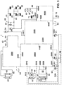
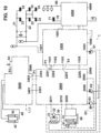
- a vehicle 10 includes a plurality of wheels 20, a cooling fan 31, an equipment 41 for carrying out a work function of the vehicle, a plurality of hydraulic circuits 21, 22, 30, 40, 50, 70, 80, and first and second hydraulic pumps 61, 62, optionally also a third hydraulic pump 63, for supplying hydraulic pressure to the hydraulic circuits.
- the third pump 63 may be driven by a different prime mover from the other pumps, for example, by a motor M.
- a tank or tanks 64 may be arranged to hold the hydraulic fluid.
- hydraulic pressure is understood to refer to pressure or both pressure and flow of hydraulic fluid, depending on the application - for example, pressure with little or no flow may be used as a signal to control hydraulic valves, while both pressure and substantial flow may be required to operate the work equipment of the vehicle.
- the hydraulic circuits include first and second service brake circuits 21, 22, a fan circuit 30, a work function circuit 40, and a steering circuit 50, and may further include a parking brake circuit 70 and a differential lock circuit 80.
- Each service brake circuit 21, 22 includes at least one respective service brake actuator 23 for braking the wheels 20, and may also include a respective hydraulic accumulator 24.
- the first and second service brake circuits 21, 22 may be operable by a user control, e.g. a pedal 25, and optionally also by an automatic retarding system 26.
- the vehicle 10 is an articulated truck, and the first and second service brake circuits act respectively on the two front wheels of the tractor unit and the four rear wheels of the trailer unit.
- the fan circuit 30 includes a fan actuator 32 for operating the cooling fan 31, and optionally also a heat exchanger 33 which may be configured as an oil cooler from which heat is extracted to the cooling airflow from the fan.
- the fan 31 may also (or alternatively) extract heat from the coolant circuit of the engine 11 of the vehicle.
- the steering circuit 50 includes at least one steering actuator 51 for steering the wheels 20, for example, responsive to user input via steering controls 52.
- the work function circuit 40 includes at least one equipment actuator 42 for operating the equipment 41.
- the equipment 41 is a tipping body of the vehicle, and the equipment actuator 42 includes one or more hydraulic rams for raising and lowering the tipping body.
- the work equipment could be, for example, a bucket or grab or other operable tool mounted on the vehicle.
- the parking brake circuit 70 includes one or more parking brake actuators 71 for applying the parking brakes to brake the wheels 20.
- the differential lock circuit 80 includes one or more differential lock actuators 81 for selectively locking the differential at one or more points in the vehicle transmission responsive to a differential lock control input (not shown).
- the vehicle may include a work function control signal generator 43 operable by a user to generate a work function control signal S3 to control the equipment.
- the work function control signal may be for example an electrical signal or a hydraulic pressure signal.
- the work function control signal S3 is an electrical signal for raising and lowering the tipping body.
- the vehicle includes a hydraulic valve assembly 1 for controlling the hydraulic pressure (which is to say, hydraulic pressure and flow of hydraulic fluid) supplied to the various hydraulic circuits.
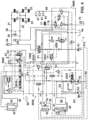
- the valve assembly 1 includes a fan and brake function module 1000 and a steering and work function module 2000.
- the fan and brake function module 1000 is configured to control a supply of hydraulic pressure to the fan circuit 30 and the service brake circuits 21, 22, and includes a first pump inlet 1003 for receiving a supply of hydraulic pressure from the first pump 61, first and second service brake outlets 1001, 1501 for supplying hydraulic pressure from the first pump inlet 1003 to the first and second service brake circuits 21, 22, and a fan supply outlet 1102 for supplying hydraulic pressure from the first pump inlet 1003 to the fan circuit 30.
- the steering and work function module 2000 is configured to control a supply of hydraulic pressure to the steering circuit 50 and the work function circuit 40, and includes a second pump inlet 2006 for receiving a supply of hydraulic pressure from the second pump 62, a steering supply outlet 2009 for supplying hydraulic pressure to the steering circuit 50 of the vehicle, and a work function outlet 2301 for supplying hydraulic pressure to the work function circuit 40 of the vehicle.
- the fan and brake function module 1000 has a first interface surface 1100 and a plurality of first ports 1101, 1102, 1103, 1104, 1105 opening through the first interface surface 1100.
- the steering and work function module 2000 has a second interface surface 2200 and a plurality of second ports 2201, 2202, 2203, 2204, 2205 opening through the second interface surface 2200.
- the fan and brake function module 1000 and the steering and work function module 2000 are separable at the first and second interface surfaces 1100, 2200 as shown in Fig. 5 , and are connectable together at the first and second interface surfaces 1100, 2200 in a connected configuration as shown in Figs. 3 and 4 , in which each of the first ports 1101, 1102, 1103, 1104, 1105 is in fluid communication with a respective one of the second ports 2201, 2202, 2203, 2204, 2205.
- the valve assembly may further include one or both of a work control module 3000 and an auxiliary module 4000, as further described below.
- Each module 1000, 2000, 3000, 4000 may include a plurality of valves arranged in or mounted on a respective valve block 1099, 2099, 3099, 4099.
- the valve block of each module may comprise internal flowpaths formed by casting, which permits a relatively more intricate configuration than can be achieved with machining and so can result in better hydraulic efficiency and so better performance of the valves which are in fluid communication via the flowpaths.
- each of valve blocks 1099, 2099, 3099 may be formed by casting.
- some or all of the valve blocks may be formed by machining, e.g. from solid bar stock, as further explained below.
- valve block 4099 may be formed by machining while at least one and, optionally, both of valve blocks 1099 and 2099, and optionally also valve block 3099, are formed by casting.
- each module has a different configuration of multiple, functionally interconnected hydraulic valves as further explained below.
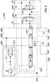
- the steering and work function module 2000 includes a steering function priority valve 2020 which is configured to restrict the supply of hydraulic pressure from the second pump 62 to the work function outlet 2301, so as to maintain the supply of hydraulic pressure from the second pump 62 to the steering supply outlet 2009, responsive to increasing load on the steering circuit 50.
- a steering function priority valve 2020 which is configured to restrict the supply of hydraulic pressure from the second pump 62 to the work function outlet 2301, so as to maintain the supply of hydraulic pressure from the second pump 62 to the steering supply outlet 2009, responsive to increasing load on the steering circuit 50.
- the steering function priority valve 2020 may be operable by a steering load sensing pressure signal S4 generated (which is to say, outputted) by the steering circuit 50 and applied to a steering load sensing pressure signal port 2008 in the steering and work function module 2000.
- the steering and work function module 2000 is configured to control a supply of hydraulic pressure from both of the first and second pumps 61, 62 to the work function outlet 2301.
- the steering and work function module 2000 further includes a fan and brake function priority valve 2021 which is configured to restrict the supply of hydraulic pressure from the first pump 61 to the work function outlet 2301, so as to maintain the supply of hydraulic pressure from the first pump 61 to the first and second service brake outlets 1001, 1501 and the fan supply outlet 1102, responsive to increasing load on any of the fan circuit 30 and the first and second service brake circuits 21, 22.
- first and second ports include first and second work function supply ports 1105, 2205 configured in fluid communication in the connected configuration to convey the hydraulic pressure from the first pump inlet 1003 of the fan and brake function module 1000 to the fan and brake function priority valve 2021 of the steering and work function module 2000.
- the steering and work function module 2000 may further include two check valves 2025 through each of which the flow of hydraulic fluid passes from a respective one of the first and second pumps 61, 62.
- the flow from the two pumps is combined downstream of the two check valves, which ensure that each pump supplies only its respective circuits, and then the combined flow is directed to the work function outlet 2301.
- the steering and work function module 2000 may further include a third pump inlet 2007 for receiving a supply of hydraulic pressure from a third pump 63, which is combined with the pressure supplied by the second pump 62 as a secondary supply to the steering circuit 50.
- the third pump 63 may be driven by a motor M.
- the motor M may be controlled by a pressure sensor (not shown) connected to port 2005, which may start the motor M when pressure supplied by the second pump 62 to the steering circuit 50 drops below a threshold pressure value.
- a control system 63' of the third pump 63 may be coupled to the steering load sensing pressure signal S4 via port 2004 to control the output of the third pump 63 while it is in operation.
- pressure supplied by the third pump 63 may be applied to port 2004 which relieves the applied pressure proportionately to the load sensing pressure signal S4.
- the control system 63' may be operable responsive to the remaining, applied pressure upstream of port 2004 which is thus proportionate to the load sensing pressure signal S4.
- the control system 63' may include a bypass valve (not shown) which is operable by the remaining, applied pressure to selectively relieve pressure across the pump 63 so as to adjust its output pressure and flow proportionately to the load sensing pressure signal S4.
- the steering and work function module 2000 may further include a steering load sensing relief valve 2027 for relieving excess pressure from the steering load sensing system to tank 64 via port 2003 to limit the steering load sensing pressure signal S4.
- the fan supply outlet 1102 may communicate in the connected configuration with port 2202 of the steering and work function module 2000.
- Port 2202 may be connected via a flowpath in the steering and work function module 2000 to another port 2011 on an exposed face of the steering and work function module 2000 which provides a convenient point to connect the pressure supplied from the first pump 61 to the fan circuit 30.
- the fan and brake function module 1000 may be configured to generate (which is to say, output) a first load sensing pressure signal S1 indicative of variations in load on the fan circuit 30 and the first and second service brake circuits 21, 22.
- the first and second ports may include first and second load sensing pressure signal ports 1103, 2203 which are configured in fluid communication in the connected configuration to convey the first load sensing pressure signal S1 from the fan and brake function module 1000 to the fan and brake function priority valve 2021 of the steering and work function module 2000.
- the fan and brake function priority valve 2021 may be operable responsive to the first load sensing pressure signal S1 to restrict the supply of hydraulic pressure from the first pump 61 to the work function outlet 2301 so as to maintain the supply of hydraulic pressure from the first pump 61 to the first and second service brake outlets 1001, 1501 and the fan supply outlet 1102.
- the fan and brake function module 1000 may include a pressure relief valve 1025 configured to relieve excess pressure supplied from the first pump 61 to the first and second service brake outlets 1001, 1501.
- the fan and brake function module 1000 may include a service brake supply valve assembly configured to control the supply of pressure from the first pump inlet 1003 to each of the first and second service brake outlets 1001, 1501, and a fan supply valve assembly configured to control the supply of pressure from the first pump inlet 1003 to the fan supply outlet 1102.
- the service brake supply valve assembly may include a brake circuit protection valve 1020 which receives a flow of hydraulic fluid from the first pump 61 and supplies it to both of the first and second service brake outlets 1001, 1501.
- the brake circuit protection valve 1020 may be operable by pressure signals from the first and second service brake circuits 21, 22, responsive to sensing that one of said circuits 21, 22 is at a higher pressure than the other, to selectively prevent a return flow of hydraulic fluid from the respective service brake circuit which is at a higher pressure.
- the fan and brake function module 1000 may include a shuttle valve 1021 which combines or resolves pressure signals from the fan circuit 30 and from the supply from the first pump 61 to the first and second service brake circuits 21, 22 to generate the first load sensing pressure signal S1.
- the fan and brake function module 1000 may further include a solenoid actuated valve 1022 arranged to modulate the pressure signal from the supply from the first pump 61 to the first and second service brake circuits 21, 22 responsive to an electrical signal (not shown) generated based on sensor output from sensors (not shown) that monitor pressure in the first and second service brake circuits 21, 22.
- valve 1022 may modulate the first load sensing pressure signal S1 to reflect demand from the first and second service brake circuits 21, 22.
- the fan supply valve assembly may include valves 1023, 1024.
- Valve 1023 is solenoid actuated and arranged to modulate the pressure signal from the fan circuit 30 responsive to an electrical signal generated based on sensor output from one or more sensors (not shown) that monitor a temperature of the hydraulic fluid and/or engine coolant.
- Valve 1024 is arranged to modulate the supply of hydraulic pressure to the fan supply outlet 1102 so as to increase or decrease the speed of the cooling fan 31 responsive to the pressure signal which is received from the fan circuit 30 and modulated by the solenoid actuated valve 1023. In this way valves 1023 and 1024 together may modulate the first load sensing pressure signal S1 to reflect demand from the fan circuit 30.
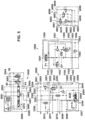
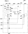
- valve assembly 1 may further include a work control module 3000 which is configured to control operation of the work function circuit 40.
- the steering and work function module 2000 may have a third interface surface 2300 and a plurality of third ports 2301, 2302, 2303, 2304 opening through the third interface surface 2300.
- the work control module 3000 has a fourth interface surface 3400 and a plurality of fourth ports 3401, 3402, 3403, 3404 opening through the fourth interface surface 3400.
- the steering and work function module 2000 and the work control module 3000 are separable at the third and fourth interface surfaces 2300, 3400 and are connectable together at the third and fourth interface surfaces 2300, 3400 in a connected configuration in which each of the third ports 2301, 2302, 2303, 2304 is in fluid communication with a respective one of the fourth ports 3401, 3402, 3403, 3404.
- the work control module 3000 may include a work function control valve assembly 3010 operable by a work function pilot pressure supply P1 responsive to the work function control signal S3 to control the operation of the at least one equipment actuator 42 in the work function circuit 40.
- a flowpath 2022 may be provided in the steering and work function module 2000 between the second interface surface 2200 and the third interface surface 2300 to convey the work function pilot pressure supply P1 from the fan and brake function module 1000 to the work function control valve assembly 3010 of the work control module 3000.
- the fan and brake function module 1000 may be configured to supply hydraulic fluid from the first pump 61 at equal pressure to the first and second service brake outlets 1001, 1501 and to a pilot pressure supply port 1101 in the first interface surface 1100, which communicates with the flowpath 2022 in the connected configuration via a corresponding pilot pressure supply port 2201 in the second interface surface 2200.
- the steering and work function module 2000 may include a pilot pressure limit valve 2026 which is configured to limit the pressure of the pilot pressure supply P1 received from port 2201.
- the pilot pressure supply P1 is supplied to the pilot valves 3012, 3013 via ports 2304, 3404 in the connected configuration.
- the work function control valve assembly 3010 may include a spool valve 3011 in fluid communication with the at least one equipment actuator 42 via first and second equipment actuation ports 3001, 3002, and in fluid communication with the combined supply of hydraulic pressure from both of the first and second pumps 61, 62 via port 3401 which communicates with the work function outlet 2301 in the connected configuration.
- the spool valve 3011 may be operable to operate the at least one equipment actuator 42 by connecting the equipment actuation ports 3001, 3002 selectively to the supply of hydraulic pressure and to tank 64.
- ports 3001, 3002 may communicate with opposite sides of the piston, so that pressurising port 3001 acts to raise the vehicle body, and pressurising port 3002 acts to lower the body.
- the spool valve 3011 may have four positions defining respectively Lower, Float, Hold, and Raise operations as known in the art.
- the work function control valve assembly 3010 may further include pilot valves 3012, 3013 operable by the work function control signal S3 received via signal connections 3003, 3004 to selectively apply the work function pilot pressure supply P1 to operate the spool valve 3011.
- valve 3012 commands the spool valve 3011 to raise the vehicle body
- valve 3013 commands the spool valve 3011 to lower the vehicle body.
- the work control module 3000 may include a pressure relief valve assembly 3014 configured to relieve to tank 64 excess pressure in the lowering branch of the work function circuit 40 at port 3002.
- the work control module 3000 may be configured to generate (which is to say, output) a second load sensing pressure signal S2 indicative of variations in load in the work function circuit 40.
- the third and fourth ports may include third and fourth load sensing signal ports 2302, 3402 configured in fluid communication in the connected configuration to convey the second load sensing pressure signal S2 from the work control module 3000 to a first load sensing shuttle valve 2023 which is arranged in the steering and work function module 2000 and which also receives the first load sensing pressure signal S1.
- the first load sensing shuttle valve 2023 combines or resolves the first and second load sensing pressure signals S1, S2 to produce a combined pressure signal S12.
- the combined pressure signal S12 may be applied to the first pump 61 via a first pump control pressure signal port 2012 in the steering and work function module 2000.
- the first pump 61 may be controlled by the combined signal S12.
- the first pump 61 may have a variable flow rate that varies responsive to the combined signal S12.
- the steering and work function module 2000 may include a second load sensing shuttle valve 2024 which combines or resolves the steering load sensing pressure signal S4 and the second load sensing pressure signal S2 to produce a combined pressure signal S24.
- the combined pressure signal S24 may be applied to the second pump 62 via a second pump control pressure signal port 2010 in the steering and work function module 2000.
- the second pump 62 may be controlled by the combined signal S24.
- the second pump 62 may have a variable flow rate that varies responsive to the combined signal S24.
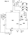
- valve assembly 1 may further include an auxiliary module 4000 which is configured to control a supply of hydraulic pressure to at least one further hydraulic circuit 70, 80 of the vehicle 10.
- the auxiliary module 4000 includes at least one auxiliary supply outlet 4002, 4004 for supplying hydraulic pressure to the at least one further hydraulic circuit 70, 80 of the vehicle 10, and a sixth interface surface 4600 with a plurality of sixth ports 4601, 4602, 4603, 4604 opening through the sixth interface surface.
- the fan and brake function module 1000 may include a corresponding, fifth interface surface 1500 and a plurality of fifth ports 1501, 1502, 1503, 1504 opening through the fifth interface surface 1500.
- the auxiliary module 4000 and the fan and brake function module 1000 may be separable at the fifth and sixth interface surfaces 1500, 4600, and connectable together at the fifth and sixth interface surfaces 1500, 4600 in a connected configuration in which each of the fifth ports 1501, 1502, 1503, 1504 is in fluid communication with a respective one of the sixth ports 4601, 4602, 4603, 4604.
- the fan and brake function module 1000 may be configured to supply pressure from the first pump inlet 1003 to the at least one auxiliary supply outlet 4002, 4004 via respective ones of the fifth and sixth ports in the connected configuration.
- the pressure is supplied via the connected ports 1502, 4602 and auxiliary supply outlet 4002 to the parking brake circuit 70, and via the connected ports 1503, 4603 and auxiliary supply outlet 4004 to the differential lock circuit 80.
- Both of the first and fifth interface surfaces 1100, 1500 may be formed on a valve block 1099 of the fan and brake function module 1000, and both of the second and third interface surfaces 2200, 2300 may be formed on a valve block 2099 of the steering and work function module 2000.
- the fourth interface surface 3400 may be formed on a valve block 3099 of the work control module 3000.
- the or each valve block is formed as a monolithic body with internal flowpaths, a plurality of valves being mounted in recesses formed in the valve block, and/or in housings mounted on the valve block, and fluidly connected together by the internal flowpaths.
- Flowpaths are indicated generally in the drawings by solid lines for main pressure supply flowpaths, and broken lines for pressure signal flowpaths or return flowpaths to tank.
- At least one, and optionally each, of the valve block 1099 of the fan and brake function module 1000 and the valve block 2099 of the steering and work function module 2000, and optionally also the valve block 3099 of the work control module 3000 may define internal hydraulic flowpaths formed by casting.
- the sixth interface surface 4600 may be formed on a valve block 4099 of the auxiliary module 4000, wherein the valve block 4099 of the auxiliary module 4000 defines internal hydraulic flowpaths formed by machining and not by casting.
- the auxiliary module may be machined, for example, from bar stock to suit the configuration of the particular vehicle 10, while some or all of the remaining modules are cast to define a more complex internal flowpath configuration for optimal hydraulic efficiency.
- the auxiliary module 4000 may have a third service brake outlet 4001 for supplying hydraulic pressure to a respective one of the first and second service brake circuits, which in the illustrated embodiment is the second service brake circuit 22.
- the corresponding one of the first and second service brake outlets (in the illustrated embodiment, the second service brake outlet 1501) is configured as one of the fifth ports, which in the connected configuration is in fluid communication with the third service brake outlet 4001 via a flowpath 4010 formed in the valve block 4099 of the auxiliary module 4000.
- the respective fifth port 1501 is in fluid communication with the corresponding sixth port 4601 in the connected configuration, which in turn is in fluid communication with the third service brake outlet 4001 via the flowpath 4010.
- the flowpath 4010 connecting the third service brake outlet 4001 to the sixth port 4601 may similarly be formed by machining, so that the third service brake outlet can be arranged in any required location to suit the configuration of a particular vehicle.
- the auxiliary module 4000 may include a parking brake sequence valve 4020 for selectively pressurising and depressurising the auxiliary supply outlet 4002 to control the parking brake actuators 71 responsive to a pressure signal from a solenoid actuated parking brake pilot valve 4021, which is controlled by an electrical parking brake actuation signal S5 received via an electrical connection 4006 from a user control of the vehicle 10.
- a pressure reducing valve 4022 may be provided to reduce the pressure supplied from the first pump 61 to the parking brake sequence valve 4020.
- a drain connection to tank 64 may be provided via corresponding fifth and sixth ports 1504, 4604 for depressurising the parking brake circuit 70.
- the auxiliary module 4000 may further include a differential lock pressure reducing valve 4023 for reducing the pressure supplied from the first pump 61 to the differential lock circuit 80.
- Port 4005 may be configured to connect a hydraulic accumulator 72 to the supply from the first pump 61 to the pressure reducing valve 4022.
- the respective modules of the valve assembly 1 may be separated at their respective interface surfaces and connected together in a distributed configuration.
- each module is configured to service a particular functional hydraulic circuit or circuits of the vehicle, one or more of the modules can also be used in alternative configurations without the remaining one or ones of the modules.
- the unused ports on the exposed interface surface or surfaces may be closed by blanking plugs or the like (not shown).
- the valves included in each of the modules 1000 and 4000 may be selected and configured, e.g. as shown, so that the function of the respective module in supplying the respective hydraulic circuits that it serves is unimpaired when it is used on its own or with less than all of the other modules.
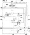
- Fig. 11 illustrates how the fan and brake function module 1000 and the auxiliary module 4000 can be used together to supply pressure from the first pump 61 to the fan, service brake, parking brake and differential lock circuits 30, 21, 22, 70, 80 of a vehicle that does not require a supply to a steering circuit or work function circuit.
- Fig. 12 illustrates how the fan and brake function module 1000 can be used on its own to supply the fan circuit 30 and first and second service brake circuits 21, 22 of a vehicle that does not require a supply to steering, parking brake or differential lock circuits. Since module 4000 is not present in this configuration, interface surface 1500 provides room for the external hydraulic connection, and so the second service brake circuit 22 is connected directly to the second service brake outlet 1501 of interface surface 1500.
- ports 3403, 2303, 2204, 1104, 1504, 4604 provide a drain connection to tank 64 via port 1002 in the fan and brake function module 1000.
- the drain connection can be taken instead from one of the ports at the respective exposed interface surface.
- Ports 2001, 2002, 2005, 4003 may be used for connection of pressure sensors.
- Various test ports 90 may be provided.
- the novel valve assembly may be used, not only to replace the conventional main valve assembly in a work vehicle with a tipping body or other work equipment, but also in vehicles with different specifications requiring less than all of the modules.
- the fan and brake function module 1000 may be used on its own or in combination with the auxiliary module 4000, with the first ports closed by suitable blanking plugs, to supply hydraulic pressure from the first pump inlet to the fan and service brake circuits, optionally also the parking brake and differential lock actuator circuits, of a vehicle that does not require the supply from the steering and work function module 2000.
- the steering and work function module 2000 and work control module 3000 may similarly be separable so that if necessary, the work control module 3000 can be located elsewhere on the vehicle to suit the configuration of the work equipment of different vehicles, or can be omitted in case the valve assembly is to be installed on a vehicle that requires a hydraulic supply to its steering circuit but does not require a hydraulic supply to operate a tipping body or other work equipment.
- the novel valve assembly provides optimal use of the pump capacity to supply work equipment that requires a combined flow when installed in a work vehicle with more than one pump.
- Either or both of the fan and brake function module 1000 and the steering and work function module 2000 may comprise a respective, cast valve block 1099, 2099 for optimum hydraulic efficiency - which is to say, the fan and brake function module 1000 may comprise a unitary valve block 1099 with internal flowpaths formed by casting, and the steering and work function module 2000 may comprise another unitary valve block 2099 with internal flowpaths formed by casting.
- the control functions of each module 1000, 2000 may be performed by a plurality of valves, all of the valves being contained in or mounted on the respective, unitary valve block of the respective module.
- the auxiliary module 4000 may comprise a machined valve block 4099, whose internal valve configuration and port layout may thus be adapted for the particular requirements of the vehicle 10 on which the valve assembly is to be fitted.
- the novel valve assembly can provide the hydraulic efficiency of a cast valve block in combination with the adaptability of a machined valve block.
- a third service brake outlet configured as an external port 4001 for one of the service brake circuits on an exposed external face of the auxiliary module 4000, it is possible to space that port 4001 farther apart from the external service brake port 1001 of the other respective service brake circuit. Since the functional valve groups supplying the respective service brake circuit via the third service brake outlet 4001 are then arranged in a different one of the modules from the auxiliary module 4000 in which the third service brake outlet 4001 is formed, this makes possible a particularly compact connected configuration of the modules while still providing room for external hydraulic connections.
- the position of the external port 4001 can be adapted to the requirements of different vehicles without compromising the hydraulic efficiency of the valve block 1099 of the fan and brake function module 1000 containing the functional valve groups that supply it, which may be a cast valve block for optimal efficiency.
- a hydraulic valve assembly 1 for a work vehicle 10 includes a fan and brake function module 1000 configured to supply hydraulic pressure from a first pump 61 to a fan circuit 30 and first and second service brake circuits 21, 22 of the vehicle, and a steering and work function module 2000 configured to receive hydraulic pressure from a second pump 62 and to supply hydraulic pressure to a steering circuit 50 and a work function circuit 40 of the vehicle.
- the assembly may further include a work control module 3000 and an auxiliary module 4000.
- the modules are separably connected together at respective interface surfaces 1100, 2200, 2300, 3400, 1500, 4600.
Landscapes
- Engineering & Computer Science (AREA)
- Mechanical Engineering (AREA)
- Transportation (AREA)
- General Engineering & Computer Science (AREA)
- Structural Engineering (AREA)
- Civil Engineering (AREA)
- Mining & Mineral Resources (AREA)
- Chemical & Material Sciences (AREA)
- Combustion & Propulsion (AREA)
- Physics & Mathematics (AREA)
- Fluid Mechanics (AREA)
- Power Steering Mechanism (AREA)
- Valves And Accessory Devices For Braking Systems (AREA)
- Fluid-Pressure Circuits (AREA)
Claims (9)
- Hydraulikanordnung (1) zur Verwendung in einem Fahrzeug (10), wobei das Fahrzeug (10) einschließt:eine Vielzahl von Rädern (20),ein Kühlgebläse (31),eine Einrichtung (41) zum Ausführen einer Arbeitsfunktion des Fahrzeugs,eine Vielzahl von Hydraulikkreisen (21, 22, 30, 40, 50); undeine erste und eine zweite Hydraulikpumpe (61, 62) zum Zuführen von Hydraulikdruck zu den Hydraulikkreisen, wobei:
die Hydraulikkreise umfassen:einen ersten und einen zweiten Betriebsbremsenkreis (21, 22), wobei jeder Betriebsbremsenkreis (21, 22) mindestens einen jeweiligen Betriebsbremsenaktuator (23) zum Abbremsen der Räder (20) umfasst,einen Gebläsekreis (30), der einen Gebläseaktuator (32) zum Betreiben des Kühlgebläses (31) einschließt,einen Lenkkreis (50), der mindestens einen Lenkaktuator (51) zum Lenken der Räder (20) einschließt; undeinen Arbeitsfunktionskreis (40), der mindestens einen Einrichtungsaktuator (42) zum Betreiben der Einrichtung (41) einschließt;die Hydraulikanordnung (1) umfasst:ein Gebläse- und Bremsfunktionsmodul (1000), das konfiguriert ist, um eine Zufuhr von Hydraulikdruck an den Gebläsekreis (30) und die Betriebsbremsenkreise (21, 22) zu steuern, undein Lenk- und Arbeitsfunktionsmodul (2000), das konfiguriert ist, um eine Zufuhr von Hydraulikdruck an den Lenkkreis (50) und den Arbeitsfunktionskreis (40) zu steuern;das Gebläse- und Bremsfunktionsmodul (1000) umfasst:einen ersten Pumpeneinlass (1003) zum Aufnehmen einer Zufuhr von Hydraulikdruck von der ersten Pumpe (61),einen ersten und einen zweiten Betriebsbremsenauslass (1001, 1501) zum Zuführen von Hydraulikdruck an den ersten und den zweiten Betriebsbremsenkreis (21, 22); undeinen Gebläsezufuhrauslass (1102) zum Zuführen von Hydraulikdruck an den Gebläsekreis (30);das Lenk- und Arbeitsfunktionsmodul (2000) umfasst: einen zweiten Pumpeneinlass (2006) zum Aufnehmen einer Zufuhr von Hydraulikdruck von der zweiten Pumpe (62),einen Lenkzufuhrauslass (2009) zum Zuführen von Hydraulikdruck an den Lenkkreis (50) des Fahrzeugs; undeinen Arbeitsfunktionsauslass (2301) zum Zuführen von Hydraulikdruck an den Arbeitsfunktionskreis (40) des Fahrzeugs; und wobei:das Gebläse- und Bremsfunktionsmodul (1000) eine erste Schnittstellenoberfläche (1100) und eine Vielzahl von ersten Zugängen (1101, 1102, 1103, 1104, 1105) aufweist, die sich durch die erste Schnittstellenoberfläche (1100) öffnen;das Lenk- und Arbeitsfunktionsmodul (2000) eine zweite Schnittstellenoberfläche (2200) und eine Vielzahl von zweiten Zugängen (2201, 2202, 2203, 2204, 2205) aufweist, die sich durch die zweite Schnittstellenoberfläche (2200) öffnen; unddas Gebläse- und Bremsfunktionsmodul (1000) und das Lenk- und Arbeitsfunktionsmodul (2000) an der ersten und der zweiten Schnittstellenoberfläche (1100, 2200) trennbar sind und an der ersten und der zweiten Schnittstellenoberfläche (1100, 2200) in einer verbundenen Konfiguration miteinander verbindbar sind, in der jeder der ersten Zugänge (1101, 1102, 1103, 1104, 1105) in Fluidaustausch mit einem jeweiligen der zweiten Zugänge (2201, 2202, 2203, 2204, 2205) steht;wobei das Lenk- und Arbeitsfunktionsmodul (2000) ein Lenkfunktionsprioritätsventil (2020) einschließt, das konfiguriert ist, um die Zufuhr von Hydraulikdruck von der zweiten Pumpe (62) zu dem Arbeitsfunktionsauslass (2301) zu beschränken, um die Zufuhr von Hydraulikdruck von der zweiten Pumpe (62) zu dem Lenkzufuhrauslass (2009) als Reaktion auf eine zunehmende Last auf dem Lenkkreis (50) aufrechtzuerhalten; wobei:das Lenk- und Arbeitsfunktionsmodul (2000) konfiguriert ist, um eine Zufuhr von Hydraulikdruck von sowohl der ersten als auch der zweiten Pumpe (61, 62) an den Arbeitsfunktionsauslass (2301) zu steuern;das Lenk- und Arbeitsfunktionsmodul (2000) ein Gebläse- und Bremsfunktionsprioritätsventil (2021) einschließt, das konfiguriert ist, um die Zufuhr von Hydraulikdruck von der ersten Pumpe (61) zu dem Arbeitsfunktionsauslass (2301) zu beschränken, um die Zufuhr von Hydraulikdruck von der ersten Pumpe (61) zu dem ersten und dem zweiten Betriebsbremsenauslass (1001, 1501) und dem Gebläsezufuhrauslass (1102) als Reaktion auf die zunehmende Last auf einen des Gebläsekreises (30) und des ersten und des zweiten Betriebsbremsenkreises (21, 22) aufrechtzuerhalten; undder erste und der zweite Zugang einen ersten und einen zweiten Arbeitsfunktionszufuhrzugang (1105, 2205) einschließen, die in der verbundenen Konfiguration in Fluidaustausch konfiguriert sind, um den Hydraulikdruck von dem ersten Pumpeneinlass (1003) des Gebläse- und Bremsfunktionsmoduls (1000) zu dem Gebläse- und Bremsfunktionsprioritätsventil (2021) des Lenk- und Arbeitsfunktionsmoduls (2000) zu übermitteln. - Hydraulikanordnung (1) nach Anspruch 1, wobei:das Gebläse- und Bremsfunktionsmodul (1000) konfiguriert ist, um ein erstes Lasterfassungsdrucksignal (S1) zu erzeugen, hinweisend auf Schwankungen der Last auf dem Gebläsekreis (30) und dem ersten und dem zweiten Betriebsbremsenkreis (21, 22);der erste und der zweite Zugang einen ersten und einen zweiten Lasterfassungsdrucksignalzugang (1103, 2203) einschließen, die in der verbundenen Konfiguration in Fluidaustausch konfiguriert sind, um das erste Lasterfassungsdrucksignal (S1) von dem Gebläse- und Bremsfunktionsmodul (1000) zu dem Gebläse- und Bremsfunktionsprioritätsventil (2021) des Lenk- und Arbeitsfunktionsmoduls (2000) zu übermitteln;das Gebläse- und Bremsfunktionsprioritätsventil (2021) als Reaktion auf das erste Lasterfassungsdrucksignal (S1) betriebsfähig ist, um die Zufuhr von Hydraulikdruck von der ersten Pumpe (61) zu dem Arbeitsfunktionsauslass (2301) zu beschränken, um die Zufuhr von Hydraulikdruck von der ersten Pumpe (61) zu dem ersten und dem zweiten Betriebsbremsenauslass (1001, 1501) und dem Gebläsezufuhrauslass (1102) aufrechtzuerhalten.
- Hydraulikanordnung (1) nach Anspruch 1, die ferner ein Arbeitssteuermodul (3000) einschließt, das konfiguriert ist, um einen Betrieb des Arbeitsfunktionskreises (40) zu steuern, wobei:das Lenk- und Arbeitsfunktionsmodul (2000) eine dritte Schnittstellenoberfläche (2300) und eine Vielzahl von dritten Zugängen (2301, 2302, 2303, 2304) einschließt, die sich durch die dritte Schnittstellenoberfläche (2300) öffnen;das Arbeitssteuermodul (3000) eine vierte Schnittstellenoberfläche (3400) und eine Vielzahl von vierten Zugängen (3401, 3402, 3403, 3404) aufweist, die sich durch die vierte Schnittstellenoberfläche (3400) öffnen; unddas Lenk- und Arbeitsfunktionsmodul (2000) und das Arbeitssteuermodul (3000) an der dritten und der vierten Schnittstellenoberfläche (2300, 3400) trennbar sind und an der dritten und der vierten Schnittstellenoberfläche (2300, 3400) in einer verbundenen Konfiguration miteinander verbindbar sind, in der jeder der dritten Zugänge (2301, 2302, 2303, 2304) in Fluidaustausch mit einem jeweiligen der vierten Zugänge (3401, 3402, 3403, 3404) steht.
- Hydraulikanordnung (1) nach Anspruch 3, wobei:das Arbeitssteuermodul (3000) eine Arbeitsfunktionssteuerventilanordnung (3010) einschließt, die durch eine Arbeitsfunktionssteuerdruckzufuhr (P1) als Reaktion auf ein Arbeitsfunktionssteuersignal (S3) betriebsfähig ist, um den Betrieb des mindestens einen Einrichtungsaktuators (42) in dem Arbeitsfunktionskreis (40) zu steuern; undein Strömungsweg (2022) in dem Lenk- und Arbeitsfunktionsmodul (2000) zwischen der zweiten Schnittstellenoberfläche (2200) und der dritten Schnittstellenoberfläche (2300) bereitgestellt ist, um die Arbeitsfunktionssteuerdruckzufuhr (P1) von dem Gebläse- und Bremsfunktionsmodul (1000) zu der Arbeitsfunktionssteuerventilanordnung (3010) des Arbeitssteuermoduls (3000) zu übermitteln.
- Hydraulikanordnung (1) nach Anspruch 3, die ferner ein zusätzliches Modul (4000) einschließt, das konfiguriert ist, um eine Zufuhr von Hydraulikdruck zu mindestens einem weiteren Hydraulikkreis (70, 80) des Fahrzeugs (10) zu steuern, wobei:das Gebläse- und Bremsfunktionsmodul (1000) eine fünfte Schnittstellenoberfläche (1500) und eine Vielzahl von fünften Zugängen (1501, 1502, 1503, 1504) einschließt, die sich durch die fünfte Schnittstellenoberfläche (1500) öffnen;das zusätzliche Modul (4000) einschließt:mindestens einen zusätzlichen Zufuhrauslass (4002, 4004) zum Zuführen von Hydraulikdruck an den mindestens einen weiteren Hydraulikkreis (70, 80) des Fahrzeugs (10); undeine sechste Schnittstellenoberfläche (4600) und eine Vielzahl von sechsten Zugängen (4601, 4602, 4603, 4604), die sich durch die sechste Schnittstellenoberfläche (4600) öffnen;das zusätzliche Modul (4000) und das Gebläse- und Bremsfunktionsmodul (1000) an der fünften und der sechsten Schnittstellenoberfläche (1500, 4600) trennbar sind und an der fünften und der sechsten Schnittstellenoberfläche (1500, 4600) in einer verbundenen Konfiguration miteinander verbindbar sind, in der jeder der fünften Zugänge (1501, 1502, 1503, 1504) in Fluidaustausch mit einem jeweiligen der sechsten Zugänge (4601, 4602, 4603, 4604) steht; unddas Gebläse- und Bremsfunktionsmodul (1000) konfiguriert ist, um Druck von dem ersten Pumpeneinlass (1003) über jeweilige (1502, 4602; 1503, 4603) der fünften und sechsten Zugänge in der verbundenen Konfiguration an den mindestens einen zusätzlichen Zufuhrauslass (4002, 4004) zuzuführen.
- Hydraulikanordnung (1) nach Anspruch 5, wobei sowohl die erste als auch die fünfte Schnittstellenoberfläche (1100, 1500) auf einem Ventilblock (1099) des Gebläse- und Bremsfunktionsmoduls (1000) ausgebildet sind und sowohl die zweite als auch die dritte Schnittstellenoberfläche (2200, 2300) auf einem Ventilblock (2099) des Lenk- und Arbeitsfunktionsmoduls (2000) ausgebildet sind.
- Hydraulikanordnung (1) nach Anspruch 6, wobei das zusätzliche Modul (4000) einen dritten Betriebsbremsenauslass (4001) zum Zuführen von Hydraulikdruck zu einem (22) des ersten und des zweiten Betriebsbremsenkreises (21, 22) umfasst, und wobei einer (1501) des ersten und des zweiten Betriebsbremsenauslasses (1001, 1501) als einer der fünften Zugänge (1501) konfiguriert ist, die in der verbundenen Konfiguration durch einen Strömungsweg (4010) in Fluidaustausch mit dem dritten Betriebsbremsenauslass (4001) stehen, der in einem Ventilblock (4099) des zusätzlichen Moduls (4000) ausgebildet ist.
- Hydraulikanordnung (1) nach Anspruch 6, wobei:mindestens einer des Ventilblocks (1099) des Gebläse- und Bremsfunktionsmoduls (1000) und des Ventilblocks (2099) des Lenk- und Arbeitsfunktionsmoduls (2000) interne Hydraulikströmungswege definiert, die durch Gießen ausgebildet sind; unddie sechste Schnittstellenoberfläche (4600) auf einem Ventilblock (4099) des zusätzlichen Moduls (4000) ausgebildet ist, wobei der Ventilblock (4099) des zusätzlichen Moduls (4000) interne hydraulische Strömungswege definiert, die durch maschinelle Bearbeitung und nicht durch Gießen ausgebildet sind.
- Hydraulikanordnung (1) nach Anspruch 8, wobei:das zusätzliche Modul (4000) einen dritten Betriebsbremsenauslass (4001) zum Zuführen von Hydraulikdruck an einen (22) des ersten und des zweiten Betriebsbremsenkreises (21, 22) umfasst; undeiner (1501) des ersten und des zweiten Betriebsbremsenauslasses (1001, 1501) als einer der fünften Zugänge (1501) konfiguriert ist, die in der verbundenen Konfiguration durch einen Strömungsweg (4010) in Fluidaustausch mit dem dritten Betriebsbremsenauslass (4001) stehen, der durch maschinelle Bearbeitung in dem Ventilblock (4099) des zusätzlichen Moduls (4000) ausgebildet ist.
Applications Claiming Priority (2)
| Application Number | Priority Date | Filing Date | Title |
|---|---|---|---|
| US16/574,117 US10746200B1 (en) | 2019-09-18 | 2019-09-18 | Modular hydraulic valve assembly for work vehicle |
| PCT/EP2020/025408 WO2021052621A1 (en) | 2019-09-18 | 2020-09-11 | Modular hydraulic valve assembly for work vehicle |
Publications (2)
| Publication Number | Publication Date |
|---|---|
| EP4031422A1 EP4031422A1 (de) | 2022-07-27 |
| EP4031422B1 true EP4031422B1 (de) | 2024-09-11 |
Family
ID=72045901
Family Applications (1)
| Application Number | Title | Priority Date | Filing Date |
|---|---|---|---|
| EP20780093.9A Active EP4031422B1 (de) | 2019-09-18 | 2020-09-11 | Modulare hydraulische anordnung für arbeitsfahrzeug |
Country Status (4)
| Country | Link |
|---|---|
| US (1) | US10746200B1 (de) |
| EP (1) | EP4031422B1 (de) |
| CN (1) | CN114401872B (de) |
| WO (1) | WO2021052621A1 (de) |
Families Citing this family (4)
| Publication number | Priority date | Publication date | Assignee | Title |
|---|---|---|---|---|
| GB202019738D0 (en) * | 2020-12-15 | 2021-01-27 | Agco Int Gmbh | Pressurised Fluid Supply System for An Agricultural Vehicle |
| US11719265B2 (en) * | 2021-05-14 | 2023-08-08 | Caterpillar Inc. | Cooler bypass valve assembly for hydraulic system return circuit |
| CN113217500B (zh) * | 2021-06-10 | 2023-12-12 | 徐州徐工液压件有限公司 | 一种分时共享多路阀 |
| WO2024054957A1 (en) * | 2022-09-09 | 2024-03-14 | Doosan Bobcat North America, Inc. | Implement braking system |
Family Cites Families (27)
| Publication number | Priority date | Publication date | Assignee | Title |
|---|---|---|---|---|
| DE2404519C2 (de) * | 1974-01-31 | 1986-02-20 | Robert Bosch Gmbh, 7000 Stuttgart | Hydraulische Bremsanlage für ein Zugfahrzeug mit Anhänger |
| US5875630A (en) * | 1997-06-10 | 1999-03-02 | Sauer Inc. | Hydraulic drive assembly |
| DE19750367C2 (de) | 1997-11-14 | 2001-07-05 | Danfoss Fluid Power As Nordbor | Hydraulischer Fahrzeugantrieb und Ventilmodul hierfür |
| US5950429A (en) * | 1997-12-17 | 1999-09-14 | Husco International, Inc. | Hydraulic control valve system with load sensing priority |
| US6073536A (en) | 1998-03-02 | 2000-06-13 | Campbell; A. Keith | Automotive hydraulic system and method for driving a hydraulic accessory in parallel with a power steering unit |
| US6848255B2 (en) * | 2002-12-18 | 2005-02-01 | Caterpillar Inc | Hydraulic fan drive system |
| US6990999B2 (en) | 2003-05-05 | 2006-01-31 | Kjp Investments Llc | Digitally controlled modular valve system |
| CA2484317C (en) * | 2003-10-09 | 2013-07-02 | Hayes Lemmerz International, Inc. | Electric trailer brake controller |
| US7481051B2 (en) * | 2004-04-08 | 2009-01-27 | Timberjack Inc. | Tree feller power management |
| US20080066990A1 (en) * | 2006-09-20 | 2008-03-20 | Wong Albert C | Vehicular hydraulic system with pressure reducing valve |
| CN201227994Y (zh) * | 2007-09-19 | 2009-04-29 | 德尔菲技术公司 | 具有止回阀的车辆液压系统 |
| CN201220660Y (zh) * | 2007-09-19 | 2009-04-15 | 德尔菲技术公司 | 具有压力顺序阀和安全阀的车辆液压系统 |
| KR101752503B1 (ko) * | 2011-01-12 | 2017-06-30 | 두산인프라코어 주식회사 | 휠로더의 유압 펌프 제어 방법 |
| WO2012125792A2 (en) * | 2011-03-15 | 2012-09-20 | Husco International, Inc. | Multiple function hydraulic system with a variable displacement pump and a hydrostatic pump-motor |
| US8899034B2 (en) * | 2011-12-22 | 2014-12-02 | Husco International, Inc. | Hydraulic system with fluid flow summation control of a variable displacement pump and priority allocation of fluid flow |
| JP5809602B2 (ja) * | 2012-05-31 | 2015-11-11 | 日立建機株式会社 | 多連弁装置 |
| US9239085B2 (en) * | 2012-08-03 | 2016-01-19 | Caterpillar Inc. | Reduced parasitic hydraulic fan system with reversing capability |
| US9404573B2 (en) * | 2013-05-01 | 2016-08-02 | Caterpillar Inc. | Hydromechanical power management of fixed displacement boost pumps |
| US9181866B2 (en) * | 2013-06-21 | 2015-11-10 | Caterpillar Inc. | Energy recovery and cooling system for hybrid machine powertrain |
| GB2521624B (en) | 2013-12-23 | 2016-05-25 | Dolan Francis | A control apparatus for heavy machinery |
| DE102014009996A1 (de) | 2014-07-05 | 2016-01-07 | Hydac Fluidtechnik Gmbh | Ventil-Baukastensystem |
| US20160317956A1 (en) | 2015-05-01 | 2016-11-03 | Caterpillar Global Mining Llc | Combination manifold for a machine |
| US9752597B2 (en) * | 2015-09-15 | 2017-09-05 | Husco International, Inc. | Metered fluid source connection to downstream functions in PCLS systems |
| US9677572B2 (en) * | 2015-12-29 | 2017-06-13 | Caterpillar Inc. | Method and system for storing and reusing hydraulic energy |
| US10487855B2 (en) | 2016-09-29 | 2019-11-26 | Deere & Company | Electro-hydraulic system with negative flow control |
| CN107044462A (zh) | 2016-12-30 | 2017-08-15 | 江苏真绩机械制造有限公司 | 联合收割机多液压阀集成系统 |
| CN109654074B (zh) * | 2018-12-26 | 2020-04-07 | 太原理工大学 | 一种工程机械液压系统 |
-
2019
- 2019-09-18 US US16/574,117 patent/US10746200B1/en active Active
-
2020
- 2020-09-11 CN CN202080065338.9A patent/CN114401872B/zh active Active
- 2020-09-11 EP EP20780093.9A patent/EP4031422B1/de active Active
- 2020-09-11 WO PCT/EP2020/025408 patent/WO2021052621A1/en not_active Ceased
Also Published As
| Publication number | Publication date |
|---|---|
| US10746200B1 (en) | 2020-08-18 |
| EP4031422A1 (de) | 2022-07-27 |
| CN114401872B (zh) | 2023-08-22 |
| CN114401872A (zh) | 2022-04-26 |
| WO2021052621A1 (en) | 2021-03-25 |
Similar Documents
| Publication | Publication Date | Title |
|---|---|---|
| EP4031422B1 (de) | Modulare hydraulische anordnung für arbeitsfahrzeug | |
| US4898078A (en) | Hydraulic system for a work vehicle | |
| US6848255B2 (en) | Hydraulic fan drive system | |
| CA1326254C (en) | Hydraulic system for a work vehicle | |
| EP3201475B1 (de) | Mehrwegeventil | |
| US4517800A (en) | Hydraulic control system for off-highway self-propelled work machines | |
| EP4031421B1 (de) | Hydraulikventilmodul und verfahren zur versorgung des hydraulikdrucks an schaltungen eines fahrzeugs | |
| US4453451A (en) | Hydraulic steering system with automatic emergency pump flow control | |
| EP4031439B1 (de) | Hydraulisches ventilmodul für lenk- und arbeitsfunktionen bei einem arbeitsfahrzeug | |
| US4559965A (en) | Multiple compensating unloading valve circuit | |
| US6761027B2 (en) | Pressure-compensated hydraulic circuit with regeneration | |
| US4633666A (en) | Integrated hydraulic system | |
| GB2465572A (en) | Switchable source hydraulic supply system | |
| EP0913586A1 (de) | Einrichtung zur versorgung mit hydrauliköl | |
| CN217462693U (zh) | 具有多压力输出的液压系统和包括该液压系统的工程机械 | |
| CA1040062A (en) | Hydraulic system for tractor brake steering and loader valves | |
| US11359352B2 (en) | Work vehicle hydraulic system with fluid exchange reservoir | |
| JP3681516B2 (ja) | 油圧作業機の油圧回路装置 | |
| CA1044993A (en) | Hydraulic system with dual pumps for tractor brake, steering, and loader valves | |
| SU1665118A1 (ru) | Гидросистема | |
| CA1141265A (en) | Controlled pressure upstaging and flow reduction | |
| JPH0712245B2 (ja) | トラクタの油圧回路 |
Legal Events
| Date | Code | Title | Description |
|---|---|---|---|
| STAA | Information on the status of an ep patent application or granted ep patent |
Free format text: STATUS: UNKNOWN |
|
| STAA | Information on the status of an ep patent application or granted ep patent |
Free format text: STATUS: THE INTERNATIONAL PUBLICATION HAS BEEN MADE |
|
| PUAI | Public reference made under article 153(3) epc to a published international application that has entered the european phase |
Free format text: ORIGINAL CODE: 0009012 |
|
| STAA | Information on the status of an ep patent application or granted ep patent |
Free format text: STATUS: REQUEST FOR EXAMINATION WAS MADE |
|
| 17P | Request for examination filed |
Effective date: 20220329 |
|
| AK | Designated contracting states |
Kind code of ref document: A1 Designated state(s): AL AT BE BG CH CY CZ DE DK EE ES FI FR GB GR HR HU IE IS IT LI LT LU LV MC MK MT NL NO PL PT RO RS SE SI SK SM TR |
|
| DAV | Request for validation of the european patent (deleted) | ||
| DAX | Request for extension of the european patent (deleted) | ||
| STAA | Information on the status of an ep patent application or granted ep patent |
Free format text: STATUS: EXAMINATION IS IN PROGRESS |
|
| 17Q | First examination report despatched |
Effective date: 20230713 |
|
| GRAP | Despatch of communication of intention to grant a patent |
Free format text: ORIGINAL CODE: EPIDOSNIGR1 |
|
| STAA | Information on the status of an ep patent application or granted ep patent |
Free format text: STATUS: GRANT OF PATENT IS INTENDED |
|
| INTG | Intention to grant announced |
Effective date: 20240417 |
|
| GRAS | Grant fee paid |
Free format text: ORIGINAL CODE: EPIDOSNIGR3 |
|
| GRAA | (expected) grant |
Free format text: ORIGINAL CODE: 0009210 |
|
| STAA | Information on the status of an ep patent application or granted ep patent |
Free format text: STATUS: THE PATENT HAS BEEN GRANTED |
|
| P01 | Opt-out of the competence of the unified patent court (upc) registered |
Free format text: CASE NUMBER: APP_41026/2024 Effective date: 20240710 |
|
| AK | Designated contracting states |
Kind code of ref document: B1 Designated state(s): AL AT BE BG CH CY CZ DE DK EE ES FI FR GB GR HR HU IE IS IT LI LT LU LV MC MK MT NL NO PL PT RO RS SE SI SK SM TR |
|
| REG | Reference to a national code |
Ref country code: GB Ref legal event code: FG4D |
|
| REG | Reference to a national code |
Ref country code: CH Ref legal event code: EP |
|
| REG | Reference to a national code |
Ref country code: DE Ref legal event code: R096 Ref document number: 602020037609 Country of ref document: DE |
|
| REG | Reference to a national code |
Ref country code: IE Ref legal event code: FG4D |
|
| REG | Reference to a national code |
Ref country code: SE Ref legal event code: TRGR |
|
| REG | Reference to a national code |
Ref country code: LT Ref legal event code: MG9D |
|
| PG25 | Lapsed in a contracting state [announced via postgrant information from national office to epo] |
Ref country code: NO Free format text: LAPSE BECAUSE OF FAILURE TO SUBMIT A TRANSLATION OF THE DESCRIPTION OR TO PAY THE FEE WITHIN THE PRESCRIBED TIME-LIMIT Effective date: 20241211 |
|
| REG | Reference to a national code |
Ref country code: NL Ref legal event code: MP Effective date: 20240911 |
|
| PG25 | Lapsed in a contracting state [announced via postgrant information from national office to epo] |
Ref country code: GR Free format text: LAPSE BECAUSE OF FAILURE TO SUBMIT A TRANSLATION OF THE DESCRIPTION OR TO PAY THE FEE WITHIN THE PRESCRIBED TIME-LIMIT Effective date: 20241212 Ref country code: FI Free format text: LAPSE BECAUSE OF FAILURE TO SUBMIT A TRANSLATION OF THE DESCRIPTION OR TO PAY THE FEE WITHIN THE PRESCRIBED TIME-LIMIT Effective date: 20240911 |
|
| PG25 | Lapsed in a contracting state [announced via postgrant information from national office to epo] |
Ref country code: BG Free format text: LAPSE BECAUSE OF FAILURE TO SUBMIT A TRANSLATION OF THE DESCRIPTION OR TO PAY THE FEE WITHIN THE PRESCRIBED TIME-LIMIT Effective date: 20240911 |
|
| PG25 | Lapsed in a contracting state [announced via postgrant information from national office to epo] |
Ref country code: LV Free format text: LAPSE BECAUSE OF FAILURE TO SUBMIT A TRANSLATION OF THE DESCRIPTION OR TO PAY THE FEE WITHIN THE PRESCRIBED TIME-LIMIT Effective date: 20240911 |
|
| PG25 | Lapsed in a contracting state [announced via postgrant information from national office to epo] |
Ref country code: HR Free format text: LAPSE BECAUSE OF FAILURE TO SUBMIT A TRANSLATION OF THE DESCRIPTION OR TO PAY THE FEE WITHIN THE PRESCRIBED TIME-LIMIT Effective date: 20240911 |
|
| PG25 | Lapsed in a contracting state [announced via postgrant information from national office to epo] |
Ref country code: RS Free format text: LAPSE BECAUSE OF FAILURE TO SUBMIT A TRANSLATION OF THE DESCRIPTION OR TO PAY THE FEE WITHIN THE PRESCRIBED TIME-LIMIT Effective date: 20241211 Ref country code: ES Free format text: LAPSE BECAUSE OF FAILURE TO SUBMIT A TRANSLATION OF THE DESCRIPTION OR TO PAY THE FEE WITHIN THE PRESCRIBED TIME-LIMIT Effective date: 20240911 |
|
| PG25 | Lapsed in a contracting state [announced via postgrant information from national office to epo] |
Ref country code: RS Free format text: LAPSE BECAUSE OF FAILURE TO SUBMIT A TRANSLATION OF THE DESCRIPTION OR TO PAY THE FEE WITHIN THE PRESCRIBED TIME-LIMIT Effective date: 20241211 Ref country code: NO Free format text: LAPSE BECAUSE OF FAILURE TO SUBMIT A TRANSLATION OF THE DESCRIPTION OR TO PAY THE FEE WITHIN THE PRESCRIBED TIME-LIMIT Effective date: 20241211 Ref country code: LV Free format text: LAPSE BECAUSE OF FAILURE TO SUBMIT A TRANSLATION OF THE DESCRIPTION OR TO PAY THE FEE WITHIN THE PRESCRIBED TIME-LIMIT Effective date: 20240911 Ref country code: HR Free format text: LAPSE BECAUSE OF FAILURE TO SUBMIT A TRANSLATION OF THE DESCRIPTION OR TO PAY THE FEE WITHIN THE PRESCRIBED TIME-LIMIT Effective date: 20240911 Ref country code: GR Free format text: LAPSE BECAUSE OF FAILURE TO SUBMIT A TRANSLATION OF THE DESCRIPTION OR TO PAY THE FEE WITHIN THE PRESCRIBED TIME-LIMIT Effective date: 20241212 Ref country code: FI Free format text: LAPSE BECAUSE OF FAILURE TO SUBMIT A TRANSLATION OF THE DESCRIPTION OR TO PAY THE FEE WITHIN THE PRESCRIBED TIME-LIMIT Effective date: 20240911 Ref country code: ES Free format text: LAPSE BECAUSE OF FAILURE TO SUBMIT A TRANSLATION OF THE DESCRIPTION OR TO PAY THE FEE WITHIN THE PRESCRIBED TIME-LIMIT Effective date: 20240911 Ref country code: BG Free format text: LAPSE BECAUSE OF FAILURE TO SUBMIT A TRANSLATION OF THE DESCRIPTION OR TO PAY THE FEE WITHIN THE PRESCRIBED TIME-LIMIT Effective date: 20240911 |
|
| REG | Reference to a national code |
Ref country code: AT Ref legal event code: MK05 Ref document number: 1722442 Country of ref document: AT Kind code of ref document: T Effective date: 20240911 |
|
| PG25 | Lapsed in a contracting state [announced via postgrant information from national office to epo] |
Ref country code: NL Free format text: LAPSE BECAUSE OF FAILURE TO SUBMIT A TRANSLATION OF THE DESCRIPTION OR TO PAY THE FEE WITHIN THE PRESCRIBED TIME-LIMIT Effective date: 20240911 |
|
| PG25 | Lapsed in a contracting state [announced via postgrant information from national office to epo] |
Ref country code: IS Free format text: LAPSE BECAUSE OF FAILURE TO SUBMIT A TRANSLATION OF THE DESCRIPTION OR TO PAY THE FEE WITHIN THE PRESCRIBED TIME-LIMIT Effective date: 20250111 Ref country code: PT Free format text: LAPSE BECAUSE OF FAILURE TO SUBMIT A TRANSLATION OF THE DESCRIPTION OR TO PAY THE FEE WITHIN THE PRESCRIBED TIME-LIMIT Effective date: 20250113 |
|
| PG25 | Lapsed in a contracting state [announced via postgrant information from national office to epo] |
Ref country code: RO Free format text: LAPSE BECAUSE OF FAILURE TO SUBMIT A TRANSLATION OF THE DESCRIPTION OR TO PAY THE FEE WITHIN THE PRESCRIBED TIME-LIMIT Effective date: 20240911 Ref country code: SM Free format text: LAPSE BECAUSE OF FAILURE TO SUBMIT A TRANSLATION OF THE DESCRIPTION OR TO PAY THE FEE WITHIN THE PRESCRIBED TIME-LIMIT Effective date: 20240911 |
|
| PG25 | Lapsed in a contracting state [announced via postgrant information from national office to epo] |
Ref country code: EE Free format text: LAPSE BECAUSE OF FAILURE TO SUBMIT A TRANSLATION OF THE DESCRIPTION OR TO PAY THE FEE WITHIN THE PRESCRIBED TIME-LIMIT Effective date: 20240911 Ref country code: AT Free format text: LAPSE BECAUSE OF FAILURE TO SUBMIT A TRANSLATION OF THE DESCRIPTION OR TO PAY THE FEE WITHIN THE PRESCRIBED TIME-LIMIT Effective date: 20240911 |
|
| PG25 | Lapsed in a contracting state [announced via postgrant information from national office to epo] |
Ref country code: PL Free format text: LAPSE BECAUSE OF FAILURE TO SUBMIT A TRANSLATION OF THE DESCRIPTION OR TO PAY THE FEE WITHIN THE PRESCRIBED TIME-LIMIT Effective date: 20240911 Ref country code: CZ Free format text: LAPSE BECAUSE OF FAILURE TO SUBMIT A TRANSLATION OF THE DESCRIPTION OR TO PAY THE FEE WITHIN THE PRESCRIBED TIME-LIMIT Effective date: 20240911 |
|
| PG25 | Lapsed in a contracting state [announced via postgrant information from national office to epo] |
Ref country code: SK Free format text: LAPSE BECAUSE OF FAILURE TO SUBMIT A TRANSLATION OF THE DESCRIPTION OR TO PAY THE FEE WITHIN THE PRESCRIBED TIME-LIMIT Effective date: 20240911 Ref country code: IT Free format text: LAPSE BECAUSE OF FAILURE TO SUBMIT A TRANSLATION OF THE DESCRIPTION OR TO PAY THE FEE WITHIN THE PRESCRIBED TIME-LIMIT Effective date: 20240911 |
|
| REG | Reference to a national code |
Ref country code: CH Ref legal event code: PL |
|
| PG25 | Lapsed in a contracting state [announced via postgrant information from national office to epo] |
Ref country code: LU Free format text: LAPSE BECAUSE OF NON-PAYMENT OF DUE FEES Effective date: 20240911 |
|
| REG | Reference to a national code |
Ref country code: DE Ref legal event code: R097 Ref document number: 602020037609 Country of ref document: DE |
|
| PG25 | Lapsed in a contracting state [announced via postgrant information from national office to epo] |
Ref country code: MC Free format text: LAPSE BECAUSE OF FAILURE TO SUBMIT A TRANSLATION OF THE DESCRIPTION OR TO PAY THE FEE WITHIN THE PRESCRIBED TIME-LIMIT Effective date: 20240911 |
|
| PG25 | Lapsed in a contracting state [announced via postgrant information from national office to epo] |
Ref country code: DK Free format text: LAPSE BECAUSE OF FAILURE TO SUBMIT A TRANSLATION OF THE DESCRIPTION OR TO PAY THE FEE WITHIN THE PRESCRIBED TIME-LIMIT Effective date: 20240911 |
|
| REG | Reference to a national code |
Ref country code: BE Ref legal event code: MM Effective date: 20240930 |
|
| PG25 | Lapsed in a contracting state [announced via postgrant information from national office to epo] |
Ref country code: BE Free format text: LAPSE BECAUSE OF NON-PAYMENT OF DUE FEES Effective date: 20240930 |
|
| PLBE | No opposition filed within time limit |
Free format text: ORIGINAL CODE: 0009261 |
|
| STAA | Information on the status of an ep patent application or granted ep patent |
Free format text: STATUS: NO OPPOSITION FILED WITHIN TIME LIMIT |
|
| PG25 | Lapsed in a contracting state [announced via postgrant information from national office to epo] |
Ref country code: CH Free format text: LAPSE BECAUSE OF NON-PAYMENT OF DUE FEES Effective date: 20240930 |
|
| PG25 | Lapsed in a contracting state [announced via postgrant information from national office to epo] |
Ref country code: IE Free format text: LAPSE BECAUSE OF NON-PAYMENT OF DUE FEES Effective date: 20240911 |
|
| 26N | No opposition filed |
Effective date: 20250612 |
|
| PGFP | Annual fee paid to national office [announced via postgrant information from national office to epo] |
Ref country code: DE Payment date: 20250820 Year of fee payment: 6 |
|
| PGFP | Annual fee paid to national office [announced via postgrant information from national office to epo] |
Ref country code: GB Payment date: 20250822 Year of fee payment: 6 |
|
| PG25 | Lapsed in a contracting state [announced via postgrant information from national office to epo] |
Ref country code: FR Free format text: LAPSE BECAUSE OF NON-PAYMENT OF DUE FEES Effective date: 20241111 |
|
| PGFP | Annual fee paid to national office [announced via postgrant information from national office to epo] |
Ref country code: SE Payment date: 20250820 Year of fee payment: 6 |
|
| PG25 | Lapsed in a contracting state [announced via postgrant information from national office to epo] |
Ref country code: CY Free format text: LAPSE BECAUSE OF FAILURE TO SUBMIT A TRANSLATION OF THE DESCRIPTION OR TO PAY THE FEE WITHIN THE PRESCRIBED TIME-LIMIT; INVALID AB INITIO Effective date: 20200911 |
|
| PG25 | Lapsed in a contracting state [announced via postgrant information from national office to epo] |
Ref country code: HU Free format text: LAPSE BECAUSE OF FAILURE TO SUBMIT A TRANSLATION OF THE DESCRIPTION OR TO PAY THE FEE WITHIN THE PRESCRIBED TIME-LIMIT; INVALID AB INITIO Effective date: 20200911 |