EP4031431B1 - System for the generation of compressed air and for air conditioning, for a railway vehicle - Google Patents
System for the generation of compressed air and for air conditioning, for a railway vehicle Download PDFInfo
- Publication number
- EP4031431B1 EP4031431B1 EP20789664.8A EP20789664A EP4031431B1 EP 4031431 B1 EP4031431 B1 EP 4031431B1 EP 20789664 A EP20789664 A EP 20789664A EP 4031431 B1 EP4031431 B1 EP 4031431B1
- Authority
- EP
- European Patent Office
- Prior art keywords
- compressor
- electrical signal
- coupling means
- mechanical torque
- electric motor
- Prior art date
- Legal status (The legal status is an assumption and is not a legal conclusion. Google has not performed a legal analysis and makes no representation as to the accuracy of the status listed.)
- Active
Links
Images




Classifications
-
- B—PERFORMING OPERATIONS; TRANSPORTING
- B60—VEHICLES IN GENERAL
- B60T—VEHICLE BRAKE CONTROL SYSTEMS OR PARTS THEREOF; BRAKE CONTROL SYSTEMS OR PARTS THEREOF, IN GENERAL; ARRANGEMENT OF BRAKING ELEMENTS ON VEHICLES IN GENERAL; PORTABLE DEVICES FOR PREVENTING UNWANTED MOVEMENT OF VEHICLES; VEHICLE MODIFICATIONS TO FACILITATE COOLING OF BRAKES
- B60T13/00—Transmitting braking action from initiating means to ultimate brake actuator with power assistance or drive; Brake systems incorporating such transmitting means, e.g. air-pressure brake systems
- B60T13/10—Transmitting braking action from initiating means to ultimate brake actuator with power assistance or drive; Brake systems incorporating such transmitting means, e.g. air-pressure brake systems with fluid assistance, drive, or release
- B60T13/24—Transmitting braking action from initiating means to ultimate brake actuator with power assistance or drive; Brake systems incorporating such transmitting means, e.g. air-pressure brake systems with fluid assistance, drive, or release the fluid being gaseous
- B60T13/26—Compressed-air systems
-
- B—PERFORMING OPERATIONS; TRANSPORTING
- B61—RAILWAYS
- B61D—BODY DETAILS OR KINDS OF RAILWAY VEHICLES
- B61D27/00—Heating, cooling, ventilating, or air-conditioning
-
- B—PERFORMING OPERATIONS; TRANSPORTING
- B60—VEHICLES IN GENERAL
- B60H—ARRANGEMENTS OF HEATING, COOLING, VENTILATING OR OTHER AIR-TREATING DEVICES SPECIALLY ADAPTED FOR PASSENGER OR GOODS SPACES OF VEHICLES
- B60H1/00—Heating, cooling or ventilating devices
- B60H1/00357—Air-conditioning arrangements specially adapted for particular vehicles
- B60H1/00371—Air-conditioning arrangements specially adapted for particular vehicles for vehicles carrying large numbers of passengers, e.g. buses
-
- B—PERFORMING OPERATIONS; TRANSPORTING
- B60—VEHICLES IN GENERAL
- B60H—ARRANGEMENTS OF HEATING, COOLING, VENTILATING OR OTHER AIR-TREATING DEVICES SPECIALLY ADAPTED FOR PASSENGER OR GOODS SPACES OF VEHICLES
- B60H1/00—Heating, cooling or ventilating devices
- B60H1/32—Cooling devices
- B60H1/3204—Cooling devices using compression
- B60H1/3223—Cooling devices using compression characterised by the arrangement or type of the compressor
-
- B—PERFORMING OPERATIONS; TRANSPORTING
- B60—VEHICLES IN GENERAL
- B60T—VEHICLE BRAKE CONTROL SYSTEMS OR PARTS THEREOF; BRAKE CONTROL SYSTEMS OR PARTS THEREOF, IN GENERAL; ARRANGEMENT OF BRAKING ELEMENTS ON VEHICLES IN GENERAL; PORTABLE DEVICES FOR PREVENTING UNWANTED MOVEMENT OF VEHICLES; VEHICLE MODIFICATIONS TO FACILITATE COOLING OF BRAKES
- B60T17/00—Component parts, details, or accessories of power brake systems not covered by groups B60T8/00, B60T13/00 or B60T15/00, or presenting other characteristic features
- B60T17/002—Air treatment devices
- B60T17/004—Draining and drying devices
-
- B—PERFORMING OPERATIONS; TRANSPORTING
- B60—VEHICLES IN GENERAL
- B60T—VEHICLE BRAKE CONTROL SYSTEMS OR PARTS THEREOF; BRAKE CONTROL SYSTEMS OR PARTS THEREOF, IN GENERAL; ARRANGEMENT OF BRAKING ELEMENTS ON VEHICLES IN GENERAL; PORTABLE DEVICES FOR PREVENTING UNWANTED MOVEMENT OF VEHICLES; VEHICLE MODIFICATIONS TO FACILITATE COOLING OF BRAKES
- B60T17/00—Component parts, details, or accessories of power brake systems not covered by groups B60T8/00, B60T13/00 or B60T15/00, or presenting other characteristic features
- B60T17/02—Arrangements of pumps or compressors, or control devices therefor
-
- B—PERFORMING OPERATIONS; TRANSPORTING
- B60—VEHICLES IN GENERAL
- B60T—VEHICLE BRAKE CONTROL SYSTEMS OR PARTS THEREOF; BRAKE CONTROL SYSTEMS OR PARTS THEREOF, IN GENERAL; ARRANGEMENT OF BRAKING ELEMENTS ON VEHICLES IN GENERAL; PORTABLE DEVICES FOR PREVENTING UNWANTED MOVEMENT OF VEHICLES; VEHICLE MODIFICATIONS TO FACILITATE COOLING OF BRAKES
- B60T17/00—Component parts, details, or accessories of power brake systems not covered by groups B60T8/00, B60T13/00 or B60T15/00, or presenting other characteristic features
- B60T17/18—Safety devices; Monitoring
- B60T17/22—Devices for monitoring or checking brake systems; Signal devices
- B60T17/228—Devices for monitoring or checking brake systems; Signal devices for railway vehicles
-
- B—PERFORMING OPERATIONS; TRANSPORTING
- B61—RAILWAYS
- B61D—BODY DETAILS OR KINDS OF RAILWAY VEHICLES
- B61D27/00—Heating, cooling, ventilating, or air-conditioning
- B61D27/0018—Air-conditioning means, i.e. combining at least two of the following ways of treating or supplying air, namely heating, cooling or ventilating
-
- B—PERFORMING OPERATIONS; TRANSPORTING
- B61—RAILWAYS
- B61H—BRAKES OR OTHER RETARDING DEVICES SPECIALLY ADAPTED FOR RAIL VEHICLES; ARRANGEMENT OR DISPOSITION THEREOF IN RAIL VEHICLES
- B61H13/00—Actuating rail-vehicle brakes
-
- B—PERFORMING OPERATIONS; TRANSPORTING
- B61—RAILWAYS
- B61H—BRAKES OR OTHER RETARDING DEVICES SPECIALLY ADAPTED FOR RAIL VEHICLES; ARRANGEMENT OR DISPOSITION THEREOF IN RAIL VEHICLES
- B61H13/00—Actuating rail-vehicle brakes
- B61H13/20—Transmitting mechanisms
-
- B—PERFORMING OPERATIONS; TRANSPORTING
- B60—VEHICLES IN GENERAL
- B60Y—INDEXING SCHEME RELATING TO ASPECTS CROSS-CUTTING VEHICLE TECHNOLOGY
- B60Y2200/00—Type of vehicle
- B60Y2200/30—Railway vehicles
-
- Y—GENERAL TAGGING OF NEW TECHNOLOGICAL DEVELOPMENTS; GENERAL TAGGING OF CROSS-SECTIONAL TECHNOLOGIES SPANNING OVER SEVERAL SECTIONS OF THE IPC; TECHNICAL SUBJECTS COVERED BY FORMER USPC CROSS-REFERENCE ART COLLECTIONS [XRACs] AND DIGESTS
- Y02—TECHNOLOGIES OR APPLICATIONS FOR MITIGATION OR ADAPTATION AGAINST CLIMATE CHANGE
- Y02T—CLIMATE CHANGE MITIGATION TECHNOLOGIES RELATED TO TRANSPORTATION
- Y02T30/00—Transportation of goods or passengers via railways, e.g. energy recovery or reducing air resistance
Definitions
- This invention generally relates to the field of air conditioning and compressed air generation systems for railway vehicles.
- fixed trainset indicates that the configuration of the vehicle is defined in the design phase, where the composition defines which vehicles will be equipped with traction drive, and which vehicles will be towed. After the construction and composition of the train, said train will be broken down into individual vehicles only in case of maintenance due to serious structural damage associated with one of the vehicles making up the train.
- Fig. 1 illustrates a non-exclusive example of a fixed trainset 100 consisting of five cars 101, ..., 105.
- each railway vehicle making up the train 100 is equipped with a local HVAC (Heating, Ventilation, Air Conditioning) system, that is, a system for heating, ventilation and air conditioning of the passenger compartment.
- HVAC Heating, Ventilation, Air Conditioning
- the braking systems use compressed air appropriately injected into brake cylinders to generate braking force.
- Compressed air is generated by one or more compressors. Compressors for this purpose are available with different air flow rates.
- two compressors 121, 124 are installed, as illustrated by way of non-exclusive example in Fig. 1 .
- the dimensioning of the flow rate is derived from the filling speed requirements of the empty system at the daily start-up of the train, and from redundancy criteria in case of failure of at least one of the installed compressors.
- HVAC systems 111, ..., 115 are each integrated into self-contained structures, typically designed to be installed on the train roof.
- Fig. 3 illustrates a real 1:1 scale example of an HVAC system for regional trains.
- Fig. 2 shows how inside an HVAC system, in addition to various other devices, there is a compressor 201 used for compressing the refrigerant gas, said refrigerant gas exchanged with the rest 202 of the HAVC system.
- the compressor 201 is mechanically connected to a motor 203 by means of a shaft 204.
- a mechanical joint not shown in the figure, may be interposed between the motor 203 and the compressor 201 to compensate for misalignments of the two resulting half-shafts.
- An electronic unit 205 receives electrical signals 207 coming from sensors forming part of the HVAC system 202 and electrical signals 208 coming from the passenger compartments to be conditioned.
- the electronic unit 205 controls a power supply device 206.
- the power supply device 206 receives electrical energy 209 distributed on board the vehicle and powers the motor 203.
- Said power supply device 206 may be a simple remote control switch or a power frequency control device, to control said motor 203 with speed control criteria.
- a recurring power value for the motor 203 is on the scale of 10 KVA.
- An HVAC system similar in size to that illustrated in Fig. 3 , usually has a weight on the scale of 500 kg.
- AGTU systems 121, 124 are each integrated into self-contained structures, typically designed to be installed on the roof of the associated vehicle, or suspended under the body of the associated vehicle.
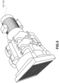
- Fig. 5 shows a real example in 1:1 scale of an AGTU system for passenger vehicles.
- Fig. 4 shows how inside an AGTU system, in addition to various other devices, there is a compressor 401 used for compressing air.
- the compressed air is sent to a dryer 402 and subsequently accumulated in a main tank 403, from which it is then distributed to the users through a main brake pipe 404.
- the compressor 401 is mechanically connected to a motor 405 by means of a resilient joint 406.
- the resilient joint 406 is used to compensate for misalignments of the two resulting half-shafts.
- a pressure switch 407 having a hysteresis turns on a power supply device 408 at a minimum pressure value, by way of non-exclusive example between 7 bar and 8 bar.
- the pressure switch 407 turns off the power supply device 408 at a maximum pressure value, by way of non-exclusive example, between 9 bar and 10 bar.
- the power supply device 408 may be a remote control switch, or more rarely, a power frequency control device, to control the motor 405 with speed control criteria, known as "soft start.”
- a typical power/flow rate ratio for the motor 405 is on the scale of 1 KVA for a flow rate of 100 L/min.
- a flow rate between 800 L/min and 1200 L/min is required, i.e. each motor 405 is required to have a power between about 8 KVA and 12 KVA.
- An AGTU system of similar dimensions to that illustrated in Fig. 5 , has a weight on the scale of 500 kg.
- the weight of the associated motor 405 is on the scale of 70 kg.
- the weight of the support frame for the complete AGTU may vary from 70 kg to 150 kg.
- oil-free In order to reduce the sources of pollution such as lubricating oils inside the compressors, the technology known as “oil-free” is currently preferred.
- the “oil-free” solution further improves the so-called “Life Cycle Cost” LCC, that is the total life cycle cost of the compressor, as the “oil-free” solution eliminates the periodic maintenance cycles linked to replacing the lubricating oil.
- air flow rates may be reached, through "oil-free” technologies, exclusively by means of piston compressors, characterized by high acoustic noise and high vibrations induced to the load-bearing structures, or to the cars of the vehicles to which they are attached.
- US 2016/377075 Al relates to a rail vehicle compressor system and method for controlling the same uses a compressor driven by an electrical machine via a drive shaft to produce compressed air for at least one compressed air tank.
- An object of this invention is to provide a solution which allows the integration of AGTU systems and HVAC systems forming part of at least one railway vehicle, or more railway vehicles of the same railway train.
- a further object is to provide a solution which allows the number of motors necessary for the generation of compressed air and for the air conditioning of at least one railway vehicle, or several railway vehicles of the same railway train, to be reduced.
- This patent relates to a solution for the integration of AGTU systems and HVAC systems forming part of the same train.
- Fig. 6 illustrates a system for the generation of compressed air and for air conditioning according to the invention.
- a single electric motor 601 may be selectively coupled to a first compressor 602 for compressed air by a first coupling means 603.
- the first compressor 602 is arranged to compress the air taken in at atmospheric pressure.
- the air is sent to a dryer 615 and subsequently accumulated in a main tank 616, from which it is then distributed to various users through a main brake pipe 617.
- the users may, by way of non-exclusive example, be the train braking system.
- the single electric motor 601 may be further selectively coupled to a second compressor 608 by a second coupling means 609.
- the second compressor 608 is joined to an HVAC 111, ..., 115 system.
- the second compressor 208 is arranged to compress the refrigerant gas, which is exchanged with the rest of the HAVC system 620.
- the system 600 comprises a single electric motor 601 arranged to generate a mechanical torque to be selectively supplied to the first compressor 602 and/or to the second compressor 608.
- the mechanical torque will be selectively supplied to the first compressor 602 and/or to the second compressor 608 as a function of a first electrical signal 619 generated by a pressure measurement device 618 and indicative of a pressure present in the main brake pipe 617, or in the main tank 616, and of at least a second electrical signal 621 coming from the air conditioning system 620 and indicative of a temperature value or a pressure value or a humidity value, and at least a third electrical signal 622 indicative of a temperature of an environment to be conditioned of the railway vehicle.
- the system may comprise an electronic control unit 607 arranged to generate a first control signal 606 for the first coupling means 603 so as to couple or uncouple the electric motor 601 and the first compressor 602, and a second control signal 612 for a second coupling means 609 so as to couple or uncouple the electric motor 601 and the second compressor 608.
- the first coupling means 603 and the second coupling means 609 may be respective electromagnetic joints.
- the first coupling means 603 connects the first and second half-shafts 604, 605, the electric motor 601 transmits mechanical torque to the first compressor 602.
- the first coupling means 603 decouples the first half-shaft 604 and the second half-shaft 605, the first compressor 602 receives no mechanical torque from the electric motor 601.
- the second coupling means 609 i.e. the electromechanical joint, couples/uncouples a third half-shaft 610 and a fourth half-shaft 611 as a function of the second electrical command 612 generated by the electronic control unit 607.
- the third half-shaft 610 is associated to the electric motor 601 and the fourth half-shaft 611 is associated to the second compressor 608.
- the electric motor 601 transmits mechanical torque to the second compressor 608.
- the second coupling means 609 decouples the third half-shaft 610 and the fourth half-shaft 611, the second compressor 608 receives no mechanical torque from the electric motor 601.
- the electromechanical joint of the first coupling means 603 and the electromechanical joint of the second coupling means 609 may each be an electromagnetic clutch.
- the electronic control unit 607 receives the first electrical signal 619 generated by the pressure measurement device 618.
- the pressure measurement device 618 may be, for example, but not exclusively, a pressure switch with hysteresis.
- the first electrical signal 619 may indicate the need to activate the first compressor 602, and therefore the need to supply the mechanical torque generated by the electric motor to the first compressor 602, when the first electrical signal 619 indicates that the pressure on the main brake pipe 617, measured by the pressure measurement device 618, reaches a minimum pressure, by way of non-exclusive example between 7 bar and 8 bar.
- the pressure measurement device 618 may be, by way of non-exclusive example, a pressure sensor generating a first electrical signal 619 proportional to the pressure value measured on the main brake pipe 617.
- the first electrical signal 619 may indicate the need to deactivate the first compressor 602, and therefore does not indicate the need to supply the mechanical torque generated by the electric motor to the first compressor 602, when the pressure on the main brake pipe 617, measured by the pressure measurement device 618, reaches a maximum pressure, by way of non-exclusive example between 9 bar and 10 bar.
- the electronic control unit 607 also receives the at least one second electrical signal 621 coming from the at least one sensor belonging to the HVAC system 620 and the at least one third electrical signal 622 coming from the at least one temperature sensor in a passenger compartment of the train to be conditioned.
- the second electrical signals 621 may be a plurality and come from several sensors, each suitable for measuring a pressure or temperature or humidity relating to the HVAC system 620
- the third electrical signals 622 may be a plurality and come from a plurality of temperature sensors arranged in various passenger compartments to be conditioned of the railway vehicle.
- the electronic control unit 607 may control a power supply device 613 arranged to receive electrical power 614 distributed on board the railway vehicle and to power the motor 601.
- the power supply device 613 may be for example a simple remote control switch or a power frequency control device, also known by the technical term of "inverter,” for controlling the electric motor 601 with speed control criteria.
- the electronic control unit 607 may activate the power supply device 613, and consequently the electric motor 601, if the first electrical signal 619 indicates the need to activate the first compressor 602, or if at least one of either the second electrical signal 621 or the third electrical signal 622 indicates the need to activate the second compressor 608, and therefore indicates the need to supply the mechanical torque generated by the electric motor to the second compressor 608.
- the electronic control unit 607 deactivates the power supply device 613, switching off the electric motor 601.
- the electronic control unit 607 continuously analyzes the first electrical signal 619 and the second electrical signal 621 and the third electrical signal 622, and decides when to activate the power supply device 613, and consequently the electric motor 601, and which one of either the first coupling means 603 or the second coupling means 609 to activate to supply suitable mechanical torque, generated by the electric motor, to the first compressor 602 and/or to the second compressor 608, respectively.
- the electric motor 601 is scaled to be able to supply a mechanical torque equivalent to the sum of the peak mechanical torques of the first and second compressors 602, 608, so that they may be activated simultaneously.
- the electronic control unit 607 activates the first coupling means 603 if the first electrical signal 619 indicates the need to activate the first compressor 602, and activates the second coupling means 609 if at least one of either the second electrical signal 621 or the third electrical signal 622 indicates the need to activate the second compressor 608.
- the electronic control unit 607 simultaneously activates both the first coupling means 603 and the second coupling means 609 so as to connect the electric motor 601 both to the first compressor 602 and to the second compressor 608.
- the electronic control unit 607 will deactivate the first coupling means 603 when the first electrical signal 619 indicates that the maximum pressure has been reached at the main tank 616, i.e. it does not indicate the need to supply the mechanical torque generated by the electric motor to the first compressor 602, or will deactivate the second coupling means 609 if at least one of either the second electrical signal 621 or the third electrical signal 622 indicates that the compression of the refrigerant gas is not necessary, i.e. it does not indicate the need to supply the mechanical torque generated by the electric motor to the second compressor 608.
- the electric motor 601 is scaled to provide the greater of either the peak mechanical torque of the first compressor 602 or the peak mechanical torque of the second compressor 608.
- the electric motor 601 may supply only the greater of the mechanical torques characteristic of the two compressors 602, 608, in the event of simultaneous requests to activate the electric motor 601 from the first electrical signal 619 and at least one of either the second electrical signal 621 or the third electrical signal 622, the electronic control unit 607 alternately activates the first coupling means 603 and the second coupling means 609, according to pre-loaded strategies, for example in a non-volatile memory 624 in the form of executable code or operating parameters, so as to alternately connect the electric motor 601 to the first compressor 602 and to the second compressor 608.
- a first strategy consists in giving absolute priority to the mechanical torque request coming from the first electrical signal 619 for the first compressor 602, since it is normally linked to the pressure request from the braking system.
- the electronic control unit 607 carries out the following steps:
- the electronic control unit 607 performs the following steps:
- a second strategy consists in giving temporary priority to the activation request coming from the first electrical signal 619, as it is normally linked to the pressure request from the braking system.
- This second strategy requires the pressure measurement device 618 to be comprised of a linear pressure transducer capable of supplying, as a first electrical signal 619, a continuous pressure value signal.
- the electronic control unit 607 carries out the following steps:
- any return of the first electrical signal 619 to the value indicating a minimum pressure at the main tank 616 reactivates the sequence from the beginning.
- the first and second compressors 602 and 608 may be volumetric compressors. It is well known that the mechanical torque required by a volumetric compressor may be considered proportional to the pressure at its output, unless torque contributions are necessary to overcome the friction of said compressor.
- the torque required by the first compressor 602 when the pressure at the main tank 616 is at its predetermined minimum value is less than the torque required by the first compressor 602 when the pressure at the main tank 616 has reached the predetermined maximum value.
- a similar consideration may be made for the second compressor 608. It is therefore possible that, if both the first and second compressors 602, 608 are at their respective minimum operating pressures, the sum of the mechanical torques necessary to move said compressors is lower than the maximum torque that may be supplied by the electric motor 601.
- an inverter device which is part of or constituting the power supply device 613 is capable of controlling the currents supplied to the electric motor 601, of knowing the instantaneous value of said currents, and of giving continuous information of said instantaneous value of said currents to the electronic control unit 607.
- a third strategy in the presence of a simultaneous request to supply mechanical torque to the respective compressors 602, 608 from the first electrical signal 619 and at least one of either the second electrical signal 621 or the third electrical signal 622 if the power supply device 613 comprises or is constituted of an inverter, provides for the electronic control unit 607 to activate simultaneously the first coupling means 603 and the second coupling means 609, so as to connect the electric motor 601 both to the first compressor 602 and to the second compressor 608, as long as the current delivered by the inverter 613 does not reach the maximum value that may be supplied by said inverter 613.
- the electronic control unit 607 may subsequently adopt the first strategy or the second strategy described above.
- Fig. 1 illustrates a non-exclusive example of a fixed trainset 100 constituted by five cars 101, ..., 105, where each car is equipped with a local HVAC system 111, ..., 115.
- the train 100 is further equipped with two local AGTU systems 121, 124. If the solution of this invention were adopted, the train 100 would take the form 700 shown in Fig. 7 , where each car 701, ..., 705 is provided with its own system for the generation of compressed air and for air conditioning 711, ..., 715.
- the air flow supplied by the two compressors integrated in the AGTU systems 121, 124 is divided between the various systems for the generation of compressed air and for air conditioning 711, ..., 715.
- This new configuration offers the benefit of eliminating the AGTU systems 121, 124, with a consequent reduction in the weight of the train 700 and an increase in the space available for the installation of other systems otherwise installed in the car.
- the distribution from a limited number of AGTU systems 121, 124 to a greater number of systems for the generation of compressed air and for air conditioning 711, ..., 715 allows the reduction of the flow rate of the compressors integrated in the systems for the generation of compressed air and for air conditioning 711, ..., 715, by way of non-exclusive example in the case of Fig. 1 and Fig. 7 with a 2:5 ratio.
- This flow rate reduction makes it possible to switch advantageously, for example, from non-lubricated piston compressors to non-lubricated "scroll" compressors, reducing the acoustic noise generated and the mechanical vibrations induced by the compressors to the relevant cars.
- the system described in Fig. 6 may be equipped with a connection to an on-board communication system 623 arranged to connect at least two of the plurality of systems for the generation of compressed air, AGTU, and for air conditioning, HVAC, 711, ..., 715 aboard said train 700. It should be considered that the main brake pipe 617 and the main tank 616 are the same for the whole train 700 and in common with all systems for the generation of compressed air and for air conditioning 711,..., 715.
- the strategy for attributing the drive torque provided by the electric motors 601 to the first and second compressors 602, 608 of each system for the generation of compressed air and for air conditioning 711, ..., 715 may be based on a distributed management.
- the first among the systems for the generation of compressed air and for air conditioning 711, ..., 715 which encounters the simultaneous request for mechanical torque to its first and second compressors 602, 608 from its electrical signals 619 and 621, 622, before prioritizing the request coming from the first electrical signal 619, as previously described in the first, second and third strategy, verifies, by exchanging information through the communication means 623, that at least one other system for the generation of compressed air and for air conditioning 711,..., 715 has requested mechanical torque to its second compressor 608 from at least one of either its second electrical signal 621 or third electrical signal 622.
- the first system for the generation of compressed air and for air conditioning will prioritize the request for mechanical torque to its first compressor 608 from at least one of its first electrical signal 621 or its second electrical signal 622.
Landscapes
- Engineering & Computer Science (AREA)
- Mechanical Engineering (AREA)
- Transportation (AREA)
- Physics & Mathematics (AREA)
- Thermal Sciences (AREA)
- Control Of Positive-Displacement Pumps (AREA)
- Electric Propulsion And Braking For Vehicles (AREA)
- Fluid-Pressure Circuits (AREA)
- Valves And Accessory Devices For Braking Systems (AREA)
Description
- This invention generally relates to the field of air conditioning and compressed air generation systems for railway vehicles.
- The most recent trains for passenger rail transport are made up of fixed trainsets. The definition of "fixed trainset" indicates that the configuration of the vehicle is defined in the design phase, where the composition defines which vehicles will be equipped with traction drive, and which vehicles will be towed. After the construction and composition of the train, said train will be broken down into individual vehicles only in case of maintenance due to serious structural damage associated with one of the vehicles making up the train.
-
Fig. 1 illustrates a non-exclusive example of a fixedtrainset 100 consisting of fivecars 101, ..., 105. - It is state of the art that each railway vehicle making up the
train 100 is equipped with a local HVAC (Heating, Ventilation, Air Conditioning) system, that is, a system for heating, ventilation and air conditioning of the passenger compartment. - It is also known that in the railway passenger transport system, the braking systems use compressed air appropriately injected into brake cylinders to generate braking force. Compressed air is generated by one or more compressors. Compressors for this purpose are available with different air flow rates. Generally two
compressors Fig. 1 . The dimensioning of the flow rate is derived from the filling speed requirements of the empty system at the daily start-up of the train, and from redundancy criteria in case of failure of at least one of the installed compressors. - It is known that the
HVAC systems 111, ..., 115 are each integrated into self-contained structures, typically designed to be installed on the train roof.Fig. 3 illustrates a real 1:1 scale example of an HVAC system for regional trains. -
Fig. 2 shows how inside an HVAC system, in addition to various other devices, there is acompressor 201 used for compressing the refrigerant gas, said refrigerant gas exchanged with therest 202 of the HAVC system. Thecompressor 201 is mechanically connected to amotor 203 by means of ashaft 204. A mechanical joint, not shown in the figure, may be interposed between themotor 203 and thecompressor 201 to compensate for misalignments of the two resulting half-shafts. Anelectronic unit 205 receiveselectrical signals 207 coming from sensors forming part of theHVAC system 202 andelectrical signals 208 coming from the passenger compartments to be conditioned. Theelectronic unit 205 controls apower supply device 206. Thepower supply device 206 receiveselectrical energy 209 distributed on board the vehicle and powers themotor 203. Saidpower supply device 206 may be a simple remote control switch or a power frequency control device, to control saidmotor 203 with speed control criteria. A recurring power value for themotor 203 is on the scale of 10 KVA. - An HVAC system, similar in size to that illustrated in
Fig. 3 , usually has a weight on the scale of 500 kg. - It is known that AGTU
systems Fig. 5 shows a real example in 1:1 scale of an AGTU system for passenger vehicles. -
Fig. 4 shows how inside an AGTU system, in addition to various other devices, there is acompressor 401 used for compressing air. The compressed air is sent to adryer 402 and subsequently accumulated in amain tank 403, from which it is then distributed to the users through amain brake pipe 404. - The
compressor 401 is mechanically connected to amotor 405 by means of aresilient joint 406. Theresilient joint 406 is used to compensate for misalignments of the two resulting half-shafts. Apressure switch 407 having a hysteresis turns on apower supply device 408 at a minimum pressure value, by way of non-exclusive example between 7 bar and 8 bar. Thepressure switch 407 turns off thepower supply device 408 at a maximum pressure value, by way of non-exclusive example, between 9 bar and 10 bar. Thepower supply device 408 may be a remote control switch, or more rarely, a power frequency control device, to control themotor 405 with speed control criteria, known as "soft start." - A typical power/flow rate ratio for the
motor 405 is on the scale of 1 KVA for a flow rate of 100 L/min. For a real case such as a passenger train as illustrated inFig. 1 , for each AGTUsystem 121, 124 a flow rate between 800 L/min and 1200 L/min is required, i.e. eachmotor 405 is required to have a power between about 8 KVA and 12 KVA. - An AGTU system, of similar dimensions to that illustrated in
Fig. 5 , has a weight on the scale of 500 kg. The weight of the associatedmotor 405 is on the scale of 70 kg. The weight of the support frame for the complete AGTU may vary from 70 kg to 150 kg. - In order to reduce the sources of pollution such as lubricating oils inside the compressors, the technology known as "oil-free" is currently preferred. The "oil-free" solution further improves the so-called "Life Cycle Cost" LCC, that is the total life cycle cost of the compressor, as the "oil-free" solution eliminates the periodic maintenance cycles linked to replacing the lubricating oil.
- The aforementioned air flow rates may be reached, through "oil-free" technologies, exclusively by means of piston compressors, characterized by high acoustic noise and high vibrations induced to the load-bearing structures, or to the cars of the vehicles to which they are attached.
- There are known "oil-free" alternatives to piston compressors, known as "scroll" compressors, characterized by a purely rotary behavior, free from acoustic noise and harmful mechanical vibrations. However, these "scroll" compressors do not reach high flow rates, on the order of 500 l/min. Wanting to use scroll compressors, it would be necessary to insert many units with the additional costs of motors and AGTU support frames, leading to an increase in weight and the required space available for their installation.
-
US 2016/377075 Al relates to a rail vehicle compressor system and method for controlling the same uses a compressor driven by an electrical machine via a drive shaft to produce compressed air for at least one compressed air tank. However, the problems described above remain unsolved. - An object of this invention is to provide a solution which allows the integration of AGTU systems and HVAC systems forming part of at least one railway vehicle, or more railway vehicles of the same railway train.
- A further object is to provide a solution which allows the number of motors necessary for the generation of compressed air and for the air conditioning of at least one railway vehicle, or several railway vehicles of the same railway train, to be reduced.
- The aforesaid and other objects and advantages are achieved, according to an aspect of the invention, by a system for the generation of compressed air and for air conditioning having the features defined in claim 1. Preferred embodiments of the invention are defined in the dependent claims, the content of which is to be understood as an integral part of this description.
- The functional and structural features of some preferred embodiments of an electronic control system for emergency and service braking according to the invention will now be described. Reference is made to the accompanying drawings, wherein:
-
Fig. 1 illustrates a non-exclusive example of a fixed trainset constituted by five cars; -
Fig. 2 illustrates the internal structure of an HVAC system; -
Fig. 3 illustrates a real example of an HVAC system for vehicles used for passenger transport. -
Fig. 4 illustrates the internal structure of an AGTU system; -
Fig. 5 illustrates an example of an AGTU system for vehicles used for passenger transport; -
Fig. 6 illustrates a system for the generation of compressed air and for air conditioning according to the invention; and -
Fig. 7 illustrates a non-exclusive example of a fixed trainset constituted by five cars, which adopts the solution illustrated inFig. 5 . - Before describing in detail a plurality of embodiments of the invention, it should be clarified that the invention is not limited in its application to the construction details and configuration of the components presented in the following description or illustrated in the drawings. The invention is capable of assuming other embodiments and of being implemented or constructed in practice in different ways. It should also be understood that the phraseology and terminology have a descriptive purpose and should not be construed as limiting. The use of "include" and "comprise" and their variations are to be understood as encompassing the elements set out below and their equivalents, as well as additional elements and the equivalents thereof.
- This patent relates to a solution for the integration of AGTU systems and HVAC systems forming part of the same train.
-
Fig. 6 illustrates a system for the generation of compressed air and for air conditioning according to the invention. - In particular, a single
electric motor 601 may be selectively coupled to afirst compressor 602 for compressed air by a first coupling means 603. - The
first compressor 602 is arranged to compress the air taken in at atmospheric pressure. The air is sent to adryer 615 and subsequently accumulated in amain tank 616, from which it is then distributed to various users through amain brake pipe 617. The users may, by way of non-exclusive example, be the train braking system. - The single
electric motor 601 may be further selectively coupled to asecond compressor 608 by a second coupling means 609. - The
second compressor 608 is joined to anHVAC 111, ..., 115 system. - The
second compressor 208 is arranged to compress the refrigerant gas, which is exchanged with the rest of theHAVC system 620. - In this way, the system 600 comprises a single
electric motor 601 arranged to generate a mechanical torque to be selectively supplied to thefirst compressor 602 and/or to thesecond compressor 608. - The mechanical torque will be selectively supplied to the
first compressor 602 and/or to thesecond compressor 608 as a function of a firstelectrical signal 619 generated by apressure measurement device 618 and indicative of a pressure present in themain brake pipe 617, or in themain tank 616, and of at least a secondelectrical signal 621 coming from theair conditioning system 620 and indicative of a temperature value or a pressure value or a humidity value, and at least a thirdelectrical signal 622 indicative of a temperature of an environment to be conditioned of the railway vehicle. - The system may comprise an
electronic control unit 607 arranged to generate afirst control signal 606 for the first coupling means 603 so as to couple or uncouple theelectric motor 601 and thefirst compressor 602, and asecond control signal 612 for a second coupling means 609 so as to couple or uncouple theelectric motor 601 and thesecond compressor 608. - The first coupling means 603 and the second coupling means 609 may be respective electromagnetic joints.
- In this case, the first coupling means 603, i.e. the electromagnetic joint, couples/uncouples a first half-
shaft 604 associated to thefirst compressor 602 and a second half-shaft 605 associated to theelectric motor 601, as a function of the firstelectrical command 606 generated by theelectronic control unit 607. - When the first coupling means 603 connects the first and second half-
shafts electric motor 601 transmits mechanical torque to thefirst compressor 602. On the other hand, when the first coupling means 603 decouples the first half-shaft 604 and the second half-shaft 605, thefirst compressor 602 receives no mechanical torque from theelectric motor 601. - The second coupling means 609, i.e. the electromechanical joint, couples/uncouples a third half-
shaft 610 and a fourth half-shaft 611 as a function of the secondelectrical command 612 generated by theelectronic control unit 607. The third half-shaft 610 is associated to theelectric motor 601 and the fourth half-shaft 611 is associated to thesecond compressor 608. - When the second coupling means 609 couples the second half-
shaft 610 and the third half-shaft 611, theelectric motor 601 transmits mechanical torque to thesecond compressor 608. On the other hand, when the second coupling means 609 decouples the third half-shaft 610 and the fourth half-shaft 611, thesecond compressor 608 receives no mechanical torque from theelectric motor 601. - For example, but not exclusively, the electromechanical joint of the first coupling means 603 and the electromechanical joint of the second coupling means 609 may each be an electromagnetic clutch.
- Still observing
Fig. 5 , theelectronic control unit 607 receives the firstelectrical signal 619 generated by thepressure measurement device 618. - The
pressure measurement device 618 may be, for example, but not exclusively, a pressure switch with hysteresis. In this case, the firstelectrical signal 619 may indicate the need to activate thefirst compressor 602, and therefore the need to supply the mechanical torque generated by the electric motor to thefirst compressor 602, when the firstelectrical signal 619 indicates that the pressure on themain brake pipe 617, measured by thepressure measurement device 618, reaches a minimum pressure, by way of non-exclusive example between 7 bar and 8 bar. - In another case, the
pressure measurement device 618 may be, by way of non-exclusive example, a pressure sensor generating a firstelectrical signal 619 proportional to the pressure value measured on themain brake pipe 617. In this case, the firstelectrical signal 619 may indicate the need to deactivate thefirst compressor 602, and therefore does not indicate the need to supply the mechanical torque generated by the electric motor to thefirst compressor 602, when the pressure on themain brake pipe 617, measured by thepressure measurement device 618, reaches a maximum pressure, by way of non-exclusive example between 9 bar and 10 bar. - Furthermore, the
electronic control unit 607 also receives the at least one secondelectrical signal 621 coming from the at least one sensor belonging to theHVAC system 620 and the at least one thirdelectrical signal 622 coming from the at least one temperature sensor in a passenger compartment of the train to be conditioned. Obviously, the secondelectrical signals 621 may be a plurality and come from several sensors, each suitable for measuring a pressure or temperature or humidity relating to theHVAC system 620, and the thirdelectrical signals 622 may be a plurality and come from a plurality of temperature sensors arranged in various passenger compartments to be conditioned of the railway vehicle. - The
electronic control unit 607 may control apower supply device 613 arranged to receiveelectrical power 614 distributed on board the railway vehicle and to power themotor 601. - The
power supply device 613 may be for example a simple remote control switch or a power frequency control device, also known by the technical term of "inverter," for controlling theelectric motor 601 with speed control criteria. - The
electronic control unit 607 may activate thepower supply device 613, and consequently theelectric motor 601, if the firstelectrical signal 619 indicates the need to activate thefirst compressor 602, or if at least one of either the secondelectrical signal 621 or the thirdelectrical signal 622 indicates the need to activate thesecond compressor 608, and therefore indicates the need to supply the mechanical torque generated by the electric motor to thesecond compressor 608. - In the event of the simultaneous absence of a request for activation of the
respective compressors electrical signal 619, and the secondelectrical signal 621 and the thirdelectrical signal 622, theelectronic control unit 607 deactivates thepower supply device 613, switching off theelectric motor 601. - Summarizing what has been set out above, the
electronic control unit 607 continuously analyzes the firstelectrical signal 619 and the secondelectrical signal 621 and the thirdelectrical signal 622, and decides when to activate thepower supply device 613, and consequently theelectric motor 601, and which one of either the first coupling means 603 or the second coupling means 609 to activate to supply suitable mechanical torque, generated by the electric motor, to thefirst compressor 602 and/or to thesecond compressor 608, respectively. - In one possible embodiment, the
electric motor 601 is scaled to be able to supply a mechanical torque equivalent to the sum of the peak mechanical torques of the first andsecond compressors - In this embodiment, the
electronic control unit 607 activates the first coupling means 603 if the firstelectrical signal 619 indicates the need to activate thefirst compressor 602, and activates the second coupling means 609 if at least one of either the secondelectrical signal 621 or the thirdelectrical signal 622 indicates the need to activate thesecond compressor 608. In case of the simultaneous presence of an activation request by the firstelectrical signal 619 and the secondelectrical signal 621 or thirdelectrical signal 622, of therespective compressors electronic control unit 607 simultaneously activates both the first coupling means 603 and the second coupling means 609 so as to connect theelectric motor 601 both to thefirst compressor 602 and to thesecond compressor 608. - The
electronic control unit 607 will deactivate the first coupling means 603 when the firstelectrical signal 619 indicates that the maximum pressure has been reached at themain tank 616, i.e. it does not indicate the need to supply the mechanical torque generated by the electric motor to thefirst compressor 602, or will deactivate the second coupling means 609 if at least one of either the secondelectrical signal 621 or the thirdelectrical signal 622 indicates that the compression of the refrigerant gas is not necessary, i.e. it does not indicate the need to supply the mechanical torque generated by the electric motor to thesecond compressor 608. - In a further possible embodiment, the
electric motor 601 is scaled to provide the greater of either the peak mechanical torque of thefirst compressor 602 or the peak mechanical torque of thesecond compressor 608. - In this further embodiment, since the
electric motor 601 may supply only the greater of the mechanical torques characteristic of the twocompressors electric motor 601 from the firstelectrical signal 619 and at least one of either the secondelectrical signal 621 or the thirdelectrical signal 622, theelectronic control unit 607 alternately activates the first coupling means 603 and the second coupling means 609, according to pre-loaded strategies, for example in anon-volatile memory 624 in the form of executable code or operating parameters, so as to alternately connect theelectric motor 601 to thefirst compressor 602 and to thesecond compressor 608. - For example, but not exclusively, a first strategy consists in giving absolute priority to the mechanical torque request coming from the first
electrical signal 619 for thefirst compressor 602, since it is normally linked to the pressure request from the braking system. - In the presence of a mechanical torque request from the first
electrical signal 619, theelectronic control unit 607 carries out the following steps: - activate the
power supply device 613, if it is not already activated; - deactivate the second coupling means 609, if this had already been activated due to an ongoing request from at least one of either the second
electrical signal 621 or the thirdelectrical signal 622; - activate the first coupling means 603, keeping it activated until the pressure at the
main tank 616 has reached the predetermined maximum value. - When the pressure at the
main tank 616 has reached the predetermined maximum value, theelectronic control unit 607 performs the following steps: - deactivate the first coupling means 603;
- activate the second coupling means 609, if there is an ongoing request from at least one of either the second
electrical signal 621 or the thirdelectrical signal 622; - deactivate or keep deactivated the second mechanical coupling means 609 and deactivate the
power supply device 613 if a request from the secondelectrical signal 621 and the thirdelectrical signal 622 fails or is not present. - If, during the phase wherein the second coupling means 609 is activated, a request occurs again from the first
electrical signal 619, the cycle starts again. - By way of non-exclusive example, a second strategy consists in giving temporary priority to the activation request coming from the first
electrical signal 619, as it is normally linked to the pressure request from the braking system. This second strategy requires thepressure measurement device 618 to be comprised of a linear pressure transducer capable of supplying, as a firstelectrical signal 619, a continuous pressure value signal. - In the presence of a mechanical torque request from the first
electrical signal 619, theelectronic control unit 607 carries out the following steps: - activate the
power supply device 613, if it is not already activated; - deactivate the second coupling means 609, if this is already activated due to an ongoing request by at least one of either the second
electrical signal 621 or the thirdelectrical signal 622; - activate the first coupling means 603, keeping it activated until the pressure at the
main tank 616 has reached a first intermediate pressure value comprised between the minimum value and the predetermined maximum value, said first pressure value being sufficient to ensure, by way of non-exclusive example, at least one emergency braking; - having reached said first intermediate value, deactivate the first coupling means 603, and activate the second coupling means 609;
- when the second
electrical signal 621 and the thirdelectrical signal 622 indicate that the request for mechanical torque for thesecond compressor 608 has ended, deactivate the second coupling means 609 and reactivate the first coupling means 603; - when the first
electrical signal 619 indicates that the predetermined maximum pressure value has been reached, deactivate the first coupling means 603 and deactivate thepower supply device 613. - During the described sequence, any return of the first
electrical signal 619 to the value indicating a minimum pressure at themain tank 616 reactivates the sequence from the beginning. - The first and
second compressors - Based on this definition, it may be defined that the torque required by the
first compressor 602 when the pressure at themain tank 616 is at its predetermined minimum value is less than the torque required by thefirst compressor 602 when the pressure at themain tank 616 has reached the predetermined maximum value. A similar consideration may be made for thesecond compressor 608. It is therefore possible that, if both the first andsecond compressors electric motor 601. - It is known that an inverter device which is part of or constituting the
power supply device 613 is capable of controlling the currents supplied to theelectric motor 601, of knowing the instantaneous value of said currents, and of giving continuous information of said instantaneous value of said currents to theelectronic control unit 607. - By way of non-exclusive example, a third strategy in the presence of a simultaneous request to supply mechanical torque to the
respective compressors electrical signal 619 and at least one of either the secondelectrical signal 621 or the thirdelectrical signal 622, if thepower supply device 613 comprises or is constituted of an inverter, provides for theelectronic control unit 607 to activate simultaneously the first coupling means 603 and the second coupling means 609, so as to connect theelectric motor 601 both to thefirst compressor 602 and to thesecond compressor 608, as long as the current delivered by theinverter 613 does not reach the maximum value that may be supplied by saidinverter 613. - When the maximum deliverable current value is reached by the inverter as a consequence of the progressive increase of the pressures downstream of the first and
second compressors electronic control unit 607 may subsequently adopt the first strategy or the second strategy described above. -
Fig. 1 illustrates a non-exclusive example of a fixedtrainset 100 constituted by fivecars 101, ..., 105, where each car is equipped with alocal HVAC system 111, ..., 115. Thetrain 100 is further equipped with twolocal AGTU systems train 100 would take theform 700 shown inFig. 7 , where eachcar 701, ..., 705 is provided with its own system for the generation of compressed air and forair conditioning 711, ..., 715. - In this case, the air flow supplied by the two compressors integrated in the
AGTU systems air conditioning 711, ..., 715. - This new configuration, illustrated in
Fig. 7 , offers the benefit of eliminating theAGTU systems train 700 and an increase in the space available for the installation of other systems otherwise installed in the car. - Furthermore, the distribution from a limited number of
AGTU systems air conditioning 711, ..., 715 allows the reduction of the flow rate of the compressors integrated in the systems for the generation of compressed air and forair conditioning 711, ..., 715, by way of non-exclusive example in the case ofFig. 1 andFig. 7 with a 2:5 ratio. This flow rate reduction makes it possible to switch advantageously, for example, from non-lubricated piston compressors to non-lubricated "scroll" compressors, reducing the acoustic noise generated and the mechanical vibrations induced by the compressors to the relevant cars. - The system described in
Fig. 6 may be equipped with a connection to an on-board communication system 623 arranged to connect at least two of the plurality of systems for the generation of compressed air, AGTU, and for air conditioning, HVAC, 711, ..., 715 aboard saidtrain 700. It should be considered that themain brake pipe 617 and themain tank 616 are the same for thewhole train 700 and in common with all systems for the generation of compressed air and forair conditioning 711,..., 715. - In this case, the strategy for attributing the drive torque provided by the
electric motors 601 to the first andsecond compressors air conditioning 711, ..., 715 may be based on a distributed management. - The first among the systems for the generation of compressed air and for
air conditioning 711, ..., 715 which encounters the simultaneous request for mechanical torque to its first andsecond compressors electrical signals electrical signal 619, as previously described in the first, second and third strategy, verifies, by exchanging information through the communication means 623, that at least one other system for the generation of compressed air and forair conditioning 711,..., 715 has requested mechanical torque to itssecond compressor 608 from at least one of either its secondelectrical signal 621 or thirdelectrical signal 622. In this case, the first system for the generation of compressed air and for air conditioning will prioritize the request for mechanical torque to itsfirst compressor 608 from at least one of its firstelectrical signal 621 or its secondelectrical signal 622. - In the presence of communication means 623 that allows the
electronic control units 607 of the two or more systems for the generation of compressed air and forair conditioning 711, ..., 715 to communicate with each other, other distributed strategies may be achieved, similar to the strategies described above, always globally prioritizing the request to supply themain tank 616 when the pressure value inside it has reached the minimum value. - Various aspects and embodiments of a system for the generation of compressed air and for air conditioning according to the invention have been described. It is understood that each embodiment may be combined with any other embodiment. Furthermore, the invention is not limited to the described embodiments, but may be varied within the scope defined by the appended claims.
Claims (10)
- System (600) for the generation of compressed air and for air conditioning, for at least one railway vehicle (701, ..., 705), wherein said system (600) comprises a first compressor (602) arranged to generate compressed air to supply a main tank (616) and a main brake pipe (617) of the railway vehicle through an air drying unit (615) and a second compressor (608) arranged to compress a refrigerant gas for an air conditioning system (620) of the at least one railway vehicle;
the system (600) being characterized in that it comprises a single electric motor (601) arranged to generate a mechanical torque adapted to be selectively provided to the first compressor (602), or to the second compressor (608), or simultaneously to both the first compressor (602) and to the second compressor (608) , as a function of:- a first electrical signal (619) generated by a pressure measurement device (618) and indicative of a pressure present in the main brake pipe (617), or in the main tank (616); and- at least one second electrical signal (621) coming from the conditioning system (620) and indicative of a temperature value or a pressure value or a humidity value, and at least a third electrical signal (622) indicative of a temperature of an environment to be conditioned of the railway vehicle. - System (600) according to claim 1, comprising an electronic control unit (607) to control said system (600), a first coupling means and a second coupling means;the electronic control unit (607) being arranged to receive the first electrical signal (619), the at least one second electrical signal (621) and the at least one third electrical signal (622);the electronic control unit (607) being arranged to activate a power supply device (613), powered by an electric power source (614), to supply said single electric motor (601) when the first electrical signal (619) indicates the need for mechanical torque for the first compressor (602), or if at least one of either the second electrical signal (621) or the third electrical signal (622) indicates the need for mechanical torque for the second compressor (608);the electronic control unit (607) being arranged to generate:- a first control signal (606) for the first coupling means (603) arranged to couple or decouple the electric motor (601) and the first compressor (602);- a second control signal (612) for the second coupling means (609) arranged to couple or decouple the electric motor (601) and the second compressor (608).
- System (600) according to claim 2, wherein the electronic unit (607) includes a non-volatile memory (624) to preventively store control strategies of said system (600).
- System (600) according to claim 2 or 3, wherein:- the first and second compressors (602, 608) each require their own peak mechanical torque, and the electric motor (601) is able to provide a mechanical torque equal to, or greater than, the sum of the peak mechanical torques required by the first and second compressors (602, 608);- when only the first electrical signal (619) coming from the pressure measurement device (618) indicates the need for mechanical torque for the first compressor (602), the electronic control unit (607) is arranged to operate on the first coupling means (603) and on the second coupling means (609) of said system (600) to provide the mechanical torque generated by the electric motor only to the first compressor (602); and- when only at least one of either the second electrical signal (621) or the third electrical signal (622) indicates the need for mechanical torque for the second compressor (608), the electronic unit (607) is arranged to operate on the first coupling means (603) and on the second coupling means (609) to provide the mechanical torque generated by the electric motor only to the second compressor (608);- when simultaneously the first electrical signal (619) coming from the pressure measurement device (618) indicates the need for mechanical torque for the first compressor (602) and at least one of either the second electrical signal (621) or the third electrical signal (622) indicates the need for mechanical torque for the second compressor (608), the electronic unit (607) is arranged to operate on the first coupling means (603) and on the second coupling means (609) to simultaneously supply the mechanical torque generated by the electric motor to the first compressor (602) and to the second compressor (608).
- System (600) according to claim 2 or 3, wherein:- the first and second compressors (602, 608) each require their own peak mechanical torque, and the electric motor (601) is able to provide a mechanical torque at least equal to the greater of the peak mechanical torques required by the first and second compressors (602, 608);- when only the first electrical signal (619) coming from the pressure measurement device (618) indicates the need for mechanical torque for the first compressor (602), the electronic unit (607) is arranged to operate on the first coupling means (603) and on the second coupling means (609) to provide the mechanical torque generated by the electric motor only to the first compressor (602);- when only at least one of either the second electrical signal (621) or the third electrical signal (622) coming from the air conditioning system (620) or from the environment to be conditioned indicates the need for mechanical torque for the second compressor (608), the electronic unit is arranged to operate on the first coupling means (603) and on the second coupling means (609) to provide the mechanical torque generated by the electric motor only to the second compressor (608);- when simultaneously the first electrical signal (619) coming from the pressure measurement device (618) indicates the need for mechanical torque for the first compressor (602) and at least one of either the first electrical signal (621) or the second electrical signal (622) coming from the air conditioning system (620) or from the environment to be conditioned indicates the need for mechanical torque for the second compressor (608), the electronic unit (607) is arranged to operate on the first coupling means (603) and on the second coupling means (609) to provide the mechanical torque generated by the electric motor only to the first compressor (602).
- System (600) according to any of the claims from 2 to 4, wherein:- the first and second compressors (602, 608) each require their own peak mechanical torque, and the electric motor (601) is able to provide a mechanical torque at least equal to the greater among the peak mechanical torques required by the first and second compressors (602, 608);- when only the first electrical signal (619) coming from the pressure measurement device (618) indicates the need for mechanical torque for the first compressor (602), the electronic unit (607) is arranged to operate on the first coupling means (603) and on the second coupling means (609) to provide the mechanical torque generated by the electric motor only to the first compressor (602);- when only at least one of either the second electrical signal (621) or the third electrical signal (622) coming from the air conditioning system (620) or from the environment to be conditioned indicates the need for mechanical torque for the second compressor (608), the electronic unit (607) is arranged to operate on the first coupling means (603) and on the second coupling means (609) to provide the mechanical torque generated by the electric motor only to the second compressor (608);- when simultaneously the first electrical signal (619) coming from the pressure measurement device (618) indicates a pressure value of the main tank (616) lower than a predetermined intermediate value and at least one of either the second electrical signal (621) or the third electrical signal (622) coming from the air conditioning system (620) or from the environment to be conditioned indicates the need for mechanical torque for the second compressor (608), the electronic unit (607) is arranged to operate on the first coupling means (603) and on the second coupling means (609) to provide the mechanical torque generated by the electric motor only to the first compressor (602);- when simultaneously the first electrical signal (619) coming from the pressure measurement device (618) indicates a pressure value of the main tank (616) higher than the predetermined intermediate value and at least one of either the second electrical signal (621) or the third electric signal (622) coming from the air conditioning system (620) or from the environment to be conditioned indicates the need for mechanical torque for the second compressor (608), the electronic unit (607) is arranged to operate on the first coupling means (603) and on the second coupling means (609) to provide the mechanical torque generated by the electric motor only to the second compressor (608).
- System (600) according to claim 6, wherein the predetermined intermediate pressure value is such as to ensure at least one emergency braking.
- System (600) according to any of the claims from 2 to 7, wherein:- the first coupling means (603) is an electromechanical joint arranged to mechanically couple or decouple a first half-shaft (604) associated to the first compressor (602) and a second half-shaft (605) associated to the electric motor (601), upon command of said electronic unit (607), so as to connect the electric motor (601) to the first compressor (602); and
the second coupling means (609) is an electromechanical joint arranged to mechanically couple or decouple a third half-shaft (610) associated to the electric motor (601) and a fourth half-shaft (611) associated to the second compressor (608), upon command of said electronic unit (607), so as to connect the electric motor (601) to the second compressor (608). - System (600) according to any of the claims from 2 to 8, wherein the electronic unit (607) is arranged to be connected to a further electronic unit of a further system for the generation of compressed air and for air conditioning, associated to a further railway vehicle of the train;
the electronic unit (607) and the further electronic unit being connected by a communication means (623). - System (600) according to claim 9 wherein the communication means (623) comprises a serial or wireless communication.
Applications Claiming Priority (2)
| Application Number | Priority Date | Filing Date | Title |
|---|---|---|---|
| IT102019000016490A IT201900016490A1 (en) | 2019-09-17 | 2019-09-17 | System for the generation of compressed air and for the conditioning of air, for a railway vehicle |
| PCT/IB2020/058598 WO2021053524A1 (en) | 2019-09-17 | 2020-09-16 | System for the generation of compressed air and for air conditioning, for a railway vehicle |
Publications (2)
| Publication Number | Publication Date |
|---|---|
| EP4031431A1 EP4031431A1 (en) | 2022-07-27 |
| EP4031431B1 true EP4031431B1 (en) | 2025-02-26 |
Family
ID=69375742
Family Applications (1)
| Application Number | Title | Priority Date | Filing Date |
|---|---|---|---|
| EP20789664.8A Active EP4031431B1 (en) | 2019-09-17 | 2020-09-16 | System for the generation of compressed air and for air conditioning, for a railway vehicle |
Country Status (9)
| Country | Link |
|---|---|
| US (1) | US12377706B2 (en) |
| EP (1) | EP4031431B1 (en) |
| JP (1) | JP7640534B2 (en) |
| KR (1) | KR102904216B1 (en) |
| CN (1) | CN114401873A (en) |
| ES (1) | ES3026134T3 (en) |
| HU (1) | HUE071696T2 (en) |
| IT (1) | IT201900016490A1 (en) |
| WO (1) | WO2021053524A1 (en) |
Cited By (1)
| Publication number | Priority date | Publication date | Assignee | Title |
|---|---|---|---|---|
| US12377706B2 (en) | 2019-09-17 | 2025-08-05 | Faiveley Transport Italia S.P.A. | System for the generation of compressed air and for air conditioning, for a railway vehicle |
Families Citing this family (5)
| Publication number | Priority date | Publication date | Assignee | Title |
|---|---|---|---|---|
| US12344214B2 (en) * | 2021-02-19 | 2025-07-01 | Transportation Ip Holdings, Llc | Sensor assembly, dryer, and vehicle control system using the same |
| IT202100011222A1 (en) * | 2021-05-03 | 2022-11-03 | Faiveley Transport Italia Spa | Process and system for the generation of compressed air of at least one railway vehicle |
| US20240190407A1 (en) * | 2021-04-26 | 2024-06-13 | Faiveley Transport Italia S.P.A. | Method and system for generating compressed air of at least one vehicle, particularly at least one railway vehicle |
| IT202100010484A1 (en) * | 2021-04-26 | 2022-10-26 | Faiveley Transport Italia Spa | SYSTEM FOR THE GENERATION OF COMPRESSED AIR OF AT LEAST ONE RAILWAY VEHICLE |
| US12589724B2 (en) * | 2022-04-18 | 2026-03-31 | Transportation Ip Holdings, Llc | Systems and methods for controlling vehicle brake system compressors |
Family Cites Families (33)
| Publication number | Priority date | Publication date | Assignee | Title |
|---|---|---|---|---|
| JPS5718557A (en) * | 1980-07-09 | 1982-01-30 | Hitachi Ltd | Direct current air conditioner for car |
| JP2000023301A (en) * | 1998-06-30 | 2000-01-21 | Hino Motors Ltd | Auxiliary drive for electric or hybrid vehicles |
| JP4043155B2 (en) | 1999-09-14 | 2008-02-06 | 北海道旅客鉄道株式会社 | Auxiliary drive device for railway vehicles |
| JP2002089456A (en) | 2000-09-20 | 2002-03-27 | Kawasaki Heavy Ind Ltd | Control device for electric air compressor in railway vehicle |
| TWI467541B (en) | 2004-09-16 | 2015-01-01 | 半導體能源研究所股份有限公司 | Display device and driving method thereof |
| DE102007019126B4 (en) * | 2007-04-23 | 2009-07-09 | Knorr-Bremse Systeme für Schienenfahrzeuge GmbH | Sound-enclosed compressor arrangement |
| KR20090119369A (en) * | 2008-05-16 | 2009-11-19 | 고구려엔지니어링(주) | Switchboard control system of railway vehicle |
| TWI524848B (en) | 2008-07-24 | 2016-03-11 | 石原產業股份有限公司 | Pesticidal composition |
| DE202009007803U1 (en) * | 2009-06-04 | 2010-10-21 | Samak, Nabil | Braking (or coasting) - energy use in braking thrust and / or only recovery by pump pressure braking, in compression heat (which is multiplied by the heat pump effect) as a heat source for Anergie drive circuits (inter alia, the "NZPG") |
| JP2011011722A (en) | 2009-07-06 | 2011-01-20 | Mitsubishi Fuso Truck & Bus Corp | Control device of compressor for vehicle |
| DE102009035398A1 (en) * | 2009-07-30 | 2011-02-03 | Wabco Gmbh | Power train-arrangement for e.g. hybrid commercial vehicle, has power train-electric motor for driving compressed air-compressor and auxiliary power train, where force flux flows from motor into power train or compressed air-compressor |
| EP3632724B1 (en) * | 2010-08-30 | 2021-05-19 | Mitsubishi Electric Corporation | Assembling method of vehicular air-conditioning apparatus |
| CN102806833A (en) * | 2011-06-02 | 2012-12-05 | 解志磊 | Power unit of new-energy coach |
| CN103057389B (en) * | 2011-10-21 | 2015-08-12 | 北汽福田汽车股份有限公司 | Electric powered motor integrated mechanism and electronlmobil |
| JP5988733B2 (en) | 2012-07-04 | 2016-09-07 | 三菱電機株式会社 | Vehicle air conditioning system |
| DE102012014020A1 (en) | 2012-07-14 | 2014-01-16 | Wabco Gmbh | Motor vehicle driven by an electric motor ancillaries |
| ITBO20120425A1 (en) * | 2012-08-02 | 2014-02-03 | Ferrari Spa | TURBOCHARGER PROVIDED WITH ELECTRIC MACHINE FOR A SUPER-POWERED INTERNAL COMBUSTION ENGINE |
| CN103112351B (en) * | 2013-02-17 | 2016-08-10 | 潍柴动力股份有限公司 | Electric vehicle and auxiliary machine driver, subsidiary engine drive system |
| DE102013013541B3 (en) * | 2013-08-14 | 2014-12-04 | Audi Ag | Motor vehicle with air conditioning compressor engine as a starter of the internal combustion engine |
| DE102013113556A1 (en) * | 2013-12-05 | 2015-06-11 | Knorr-Bremse Systeme für Schienenfahrzeuge GmbH | Compressor system and method for operating the compressor system depending on the current situation of the rail vehicle |
| JP6419456B2 (en) | 2014-05-15 | 2018-11-07 | ナブテスコ株式会社 | Air compressor for vehicle |
| KR20170069377A (en) | 2015-12-10 | 2017-06-21 | 동아전장주식회사 | Dual electromotive compressor for vehicle |
| DE102015225103A1 (en) | 2015-12-14 | 2017-06-14 | Robert Bosch Gmbh | Powertrain for a vehicle |
| CN106143093A (en) * | 2016-07-02 | 2016-11-23 | 江苏九龙汽车制造有限公司 | Pure electric coach process auxiliary drive integration module |
| CN106740779B (en) * | 2016-12-05 | 2020-06-02 | 潍柴动力股份有限公司 | A pure electric vehicle limp control method and system |
| FR3061454B1 (en) * | 2016-12-29 | 2019-07-05 | Liebherr-Aerospace Toulouse Sas | CONTROLLED TEMPERATURE AIR SUPPLY METHOD FOR A LAND VEHICLE CABIN AND A GROUND VEHICLE |
| CN108340758A (en) * | 2017-01-25 | 2018-07-31 | I.E.T.股份公司 | Integrated power-equipment for driving vehicle assisted system |
| CN106948954A (en) * | 2017-05-19 | 2017-07-14 | 重庆超力高科技股份有限公司 | Torque control device and torque control method, vehicle torsional moment control system |
| KR101958836B1 (en) | 2018-01-17 | 2019-07-02 | (주)유한알에스 | Brake operating unit for railway vehicles |
| US10919412B2 (en) * | 2018-09-24 | 2021-02-16 | Transportation Ip Holdings, Llc | Method and systems for an auxiliary power unit |
| CN109737044A (en) * | 2019-02-18 | 2019-05-10 | 河北乘风科技有限公司 | A kind of integral new-energy passenger air compressor machine control method |
| US20210010481A1 (en) * | 2019-07-08 | 2021-01-14 | Bendix Commercial Vehicle Systems Llc | Apparatus and method of controlling an air compressor to expel moisture from the air compressor |
| IT201900016490A1 (en) | 2019-09-17 | 2021-03-17 | Faiveley Transport Italia Spa | System for the generation of compressed air and for the conditioning of air, for a railway vehicle |
-
2019
- 2019-09-17 IT IT102019000016490A patent/IT201900016490A1/en unknown
-
2020
- 2020-09-16 US US17/753,906 patent/US12377706B2/en active Active
- 2020-09-16 ES ES20789664T patent/ES3026134T3/en active Active
- 2020-09-16 HU HUE20789664A patent/HUE071696T2/en unknown
- 2020-09-16 CN CN202080065166.5A patent/CN114401873A/en active Pending
- 2020-09-16 JP JP2022517168A patent/JP7640534B2/en active Active
- 2020-09-16 WO PCT/IB2020/058598 patent/WO2021053524A1/en not_active Ceased
- 2020-09-16 KR KR1020227011943A patent/KR102904216B1/en active Active
- 2020-09-16 EP EP20789664.8A patent/EP4031431B1/en active Active
Cited By (1)
| Publication number | Priority date | Publication date | Assignee | Title |
|---|---|---|---|---|
| US12377706B2 (en) | 2019-09-17 | 2025-08-05 | Faiveley Transport Italia S.P.A. | System for the generation of compressed air and for air conditioning, for a railway vehicle |
Also Published As
| Publication number | Publication date |
|---|---|
| HUE071696T2 (en) | 2025-09-28 |
| EP4031431A1 (en) | 2022-07-27 |
| JP2022547731A (en) | 2022-11-15 |
| CN114401873A (en) | 2022-04-26 |
| US12377706B2 (en) | 2025-08-05 |
| KR20220058629A (en) | 2022-05-09 |
| KR102904216B1 (en) | 2025-12-26 |
| WO2021053524A1 (en) | 2021-03-25 |
| JP7640534B2 (en) | 2025-03-05 |
| ES3026134T3 (en) | 2025-06-10 |
| BR112022004643A2 (en) | 2022-05-31 |
| US20220355642A1 (en) | 2022-11-10 |
| IT201900016490A1 (en) | 2021-03-17 |
Similar Documents
| Publication | Publication Date | Title |
|---|---|---|
| EP4031431B1 (en) | System for the generation of compressed air and for air conditioning, for a railway vehicle | |
| US8013469B2 (en) | System and process for power supply to a railway vehicle, converter, control unit, and air-conditioning unit for the system | |
| AU762654B2 (en) | Railway emulation brake | |
| US20100158702A1 (en) | Air compressor system | |
| CN102548817A (en) | Brake system having smart actuator for braking a rail-guided vehicle | |
| EP2927086A1 (en) | An assembly set and method for equipping a railway traction vehicle with brake energy recovery using standardised traction modules | |
| WO2012074682A1 (en) | Method and system for rail vehicle control | |
| EP3844393B1 (en) | Dual air compressor for hybrid vehicles | |
| WO2000006435A1 (en) | Railcar air motor driven generator | |
| HUT67696A (en) | Power transfer system mainly for vehicles | |
| CN105151052A (en) | Novel meter-gauge alternating current transmission internal combustion locomotive | |
| US20150210295A1 (en) | System and method for vehicle engine control | |
| RU130273U1 (en) | ELECTRIC PNEUMATIC BRAKE SYSTEM | |
| JP2010520110A (en) | Hybrid drive, method for controlling a compressed air compressor and motor vehicle with hybrid drive | |
| EA044451B1 (en) | COMPRESSED AIR PRODUCTION AND AIR CONDITIONING SYSTEM FOR RAILWAY VEHICLES | |
| CN115027434B (en) | Locomotive air source system operation control method and device | |
| EP4330111B1 (en) | Method and system for generating compressed air of at least one vehicle, particularly at least one railway vehicle | |
| BR112022004643B1 (en) | SYSTEM FOR GENERATION OF COMPRESSED AIR AND AIR CONDITIONING | |
| EP3296180B1 (en) | Rolling stock | |
| IT202100011222A1 (en) | Process and system for the generation of compressed air of at least one railway vehicle | |
| IT202100010484A1 (en) | SYSTEM FOR THE GENERATION OF COMPRESSED AIR OF AT LEAST ONE RAILWAY VEHICLE | |
| JPS582521B2 (en) | Electro-pneumatic brake system for vehicles | |
| MXPA99011550A (en) | Railway emulation brake |
Legal Events
| Date | Code | Title | Description |
|---|---|---|---|
| STAA | Information on the status of an ep patent application or granted ep patent |
Free format text: STATUS: UNKNOWN |
|
| STAA | Information on the status of an ep patent application or granted ep patent |
Free format text: STATUS: THE INTERNATIONAL PUBLICATION HAS BEEN MADE |
|
| PUAI | Public reference made under article 153(3) epc to a published international application that has entered the european phase |
Free format text: ORIGINAL CODE: 0009012 |
|
| STAA | Information on the status of an ep patent application or granted ep patent |
Free format text: STATUS: REQUEST FOR EXAMINATION WAS MADE |
|
| 17P | Request for examination filed |
Effective date: 20220329 |
|
| AK | Designated contracting states |
Kind code of ref document: A1 Designated state(s): AL AT BE BG CH CY CZ DE DK EE ES FI FR GB GR HR HU IE IS IT LI LT LU LV MC MK MT NL NO PL PT RO RS SE SI SK SM TR |
|
| DAV | Request for validation of the european patent (deleted) | ||
| DAX | Request for extension of the european patent (deleted) | ||
| P01 | Opt-out of the competence of the unified patent court (upc) registered |
Effective date: 20230530 |
|
| GRAP | Despatch of communication of intention to grant a patent |
Free format text: ORIGINAL CODE: EPIDOSNIGR1 |
|
| STAA | Information on the status of an ep patent application or granted ep patent |
Free format text: STATUS: GRANT OF PATENT IS INTENDED |
|
| INTG | Intention to grant announced |
Effective date: 20240923 |
|
| GRAS | Grant fee paid |
Free format text: ORIGINAL CODE: EPIDOSNIGR3 |
|
| GRAA | (expected) grant |
Free format text: ORIGINAL CODE: 0009210 |
|
| STAA | Information on the status of an ep patent application or granted ep patent |
Free format text: STATUS: THE PATENT HAS BEEN GRANTED |
|
| AK | Designated contracting states |
Kind code of ref document: B1 Designated state(s): AL AT BE BG CH CY CZ DE DK EE ES FI FR GB GR HR HU IE IS IT LI LT LU LV MC MK MT NL NO PL PT RO RS SE SI SK SM TR |
|
| REG | Reference to a national code |
Ref country code: GB Ref legal event code: FG4D |
|
| REG | Reference to a national code |
Ref country code: CH Ref legal event code: EP |
|
| REG | Reference to a national code |
Ref country code: DE Ref legal event code: R096 Ref document number: 602020046837 Country of ref document: DE |
|
| REG | Reference to a national code |
Ref country code: IE Ref legal event code: FG4D |
|
| REG | Reference to a national code |
Ref country code: ES Ref legal event code: FG2A Ref document number: 3026134 Country of ref document: ES Kind code of ref document: T3 Effective date: 20250610 |
|
| REG | Reference to a national code |
Ref country code: NL Ref legal event code: MP Effective date: 20250226 |
|
| PG25 | Lapsed in a contracting state [announced via postgrant information from national office to epo] |
Ref country code: RS Free format text: LAPSE BECAUSE OF FAILURE TO SUBMIT A TRANSLATION OF THE DESCRIPTION OR TO PAY THE FEE WITHIN THE PRESCRIBED TIME-LIMIT Effective date: 20250526 |
|
| PG25 | Lapsed in a contracting state [announced via postgrant information from national office to epo] |
Ref country code: FI Free format text: LAPSE BECAUSE OF FAILURE TO SUBMIT A TRANSLATION OF THE DESCRIPTION OR TO PAY THE FEE WITHIN THE PRESCRIBED TIME-LIMIT Effective date: 20250226 |
|
| PG25 | Lapsed in a contracting state [announced via postgrant information from national office to epo] |
Ref country code: PL Free format text: LAPSE BECAUSE OF FAILURE TO SUBMIT A TRANSLATION OF THE DESCRIPTION OR TO PAY THE FEE WITHIN THE PRESCRIBED TIME-LIMIT Effective date: 20250226 |
|
| REG | Reference to a national code |
Ref country code: LT Ref legal event code: MG9D |
|
| PG25 | Lapsed in a contracting state [announced via postgrant information from national office to epo] |
Ref country code: IS Free format text: LAPSE BECAUSE OF FAILURE TO SUBMIT A TRANSLATION OF THE DESCRIPTION OR TO PAY THE FEE WITHIN THE PRESCRIBED TIME-LIMIT Effective date: 20250626 Ref country code: NO Free format text: LAPSE BECAUSE OF FAILURE TO SUBMIT A TRANSLATION OF THE DESCRIPTION OR TO PAY THE FEE WITHIN THE PRESCRIBED TIME-LIMIT Effective date: 20250526 |
|
| PG25 | Lapsed in a contracting state [announced via postgrant information from national office to epo] |
Ref country code: NL Free format text: LAPSE BECAUSE OF FAILURE TO SUBMIT A TRANSLATION OF THE DESCRIPTION OR TO PAY THE FEE WITHIN THE PRESCRIBED TIME-LIMIT Effective date: 20250226 |
|
| PG25 | Lapsed in a contracting state [announced via postgrant information from national office to epo] |
Ref country code: HR Free format text: LAPSE BECAUSE OF FAILURE TO SUBMIT A TRANSLATION OF THE DESCRIPTION OR TO PAY THE FEE WITHIN THE PRESCRIBED TIME-LIMIT Effective date: 20250226 |
|
| PG25 | Lapsed in a contracting state [announced via postgrant information from national office to epo] |
Ref country code: PT Free format text: LAPSE BECAUSE OF FAILURE TO SUBMIT A TRANSLATION OF THE DESCRIPTION OR TO PAY THE FEE WITHIN THE PRESCRIBED TIME-LIMIT Effective date: 20250626 Ref country code: LV Free format text: LAPSE BECAUSE OF FAILURE TO SUBMIT A TRANSLATION OF THE DESCRIPTION OR TO PAY THE FEE WITHIN THE PRESCRIBED TIME-LIMIT Effective date: 20250226 |
|
| PG25 | Lapsed in a contracting state [announced via postgrant information from national office to epo] |
Ref country code: GR Free format text: LAPSE BECAUSE OF FAILURE TO SUBMIT A TRANSLATION OF THE DESCRIPTION OR TO PAY THE FEE WITHIN THE PRESCRIBED TIME-LIMIT Effective date: 20250527 Ref country code: BG Free format text: LAPSE BECAUSE OF FAILURE TO SUBMIT A TRANSLATION OF THE DESCRIPTION OR TO PAY THE FEE WITHIN THE PRESCRIBED TIME-LIMIT Effective date: 20250226 |
|
| REG | Reference to a national code |
Ref country code: AT Ref legal event code: MK05 Ref document number: 1770386 Country of ref document: AT Kind code of ref document: T Effective date: 20250226 |
|
| PG25 | Lapsed in a contracting state [announced via postgrant information from national office to epo] |
Ref country code: SE Free format text: LAPSE BECAUSE OF FAILURE TO SUBMIT A TRANSLATION OF THE DESCRIPTION OR TO PAY THE FEE WITHIN THE PRESCRIBED TIME-LIMIT Effective date: 20250226 |
|
| REG | Reference to a national code |
Ref country code: HU Ref legal event code: AG4A Ref document number: E071696 Country of ref document: HU |
|
| PG25 | Lapsed in a contracting state [announced via postgrant information from national office to epo] |
Ref country code: SM Free format text: LAPSE BECAUSE OF FAILURE TO SUBMIT A TRANSLATION OF THE DESCRIPTION OR TO PAY THE FEE WITHIN THE PRESCRIBED TIME-LIMIT Effective date: 20250226 |
|
| PG25 | Lapsed in a contracting state [announced via postgrant information from national office to epo] |
Ref country code: DK Free format text: LAPSE BECAUSE OF FAILURE TO SUBMIT A TRANSLATION OF THE DESCRIPTION OR TO PAY THE FEE WITHIN THE PRESCRIBED TIME-LIMIT Effective date: 20250226 |
|
| PGFP | Annual fee paid to national office [announced via postgrant information from national office to epo] |
Ref country code: DE Payment date: 20250819 Year of fee payment: 6 |
|
| PGFP | Annual fee paid to national office [announced via postgrant information from national office to epo] |
Ref country code: IT Payment date: 20250818 Year of fee payment: 6 |
|
| PGFP | Annual fee paid to national office [announced via postgrant information from national office to epo] |
Ref country code: HU Payment date: 20250829 Year of fee payment: 6 Ref country code: GB Payment date: 20250916 Year of fee payment: 6 |
|
| PG25 | Lapsed in a contracting state [announced via postgrant information from national office to epo] |
Ref country code: AT Free format text: LAPSE BECAUSE OF FAILURE TO SUBMIT A TRANSLATION OF THE DESCRIPTION OR TO PAY THE FEE WITHIN THE PRESCRIBED TIME-LIMIT Effective date: 20250226 |
|
| PGFP | Annual fee paid to national office [announced via postgrant information from national office to epo] |
Ref country code: FR Payment date: 20250915 Year of fee payment: 6 |
|
| PG25 | Lapsed in a contracting state [announced via postgrant information from national office to epo] |
Ref country code: EE Free format text: LAPSE BECAUSE OF FAILURE TO SUBMIT A TRANSLATION OF THE DESCRIPTION OR TO PAY THE FEE WITHIN THE PRESCRIBED TIME-LIMIT Effective date: 20250226 Ref country code: CZ Free format text: LAPSE BECAUSE OF FAILURE TO SUBMIT A TRANSLATION OF THE DESCRIPTION OR TO PAY THE FEE WITHIN THE PRESCRIBED TIME-LIMIT Effective date: 20250226 |
|
| PG25 | Lapsed in a contracting state [announced via postgrant information from national office to epo] |
Ref country code: RO Free format text: LAPSE BECAUSE OF FAILURE TO SUBMIT A TRANSLATION OF THE DESCRIPTION OR TO PAY THE FEE WITHIN THE PRESCRIBED TIME-LIMIT Effective date: 20250226 |
|
| PG25 | Lapsed in a contracting state [announced via postgrant information from national office to epo] |
Ref country code: SK Free format text: LAPSE BECAUSE OF FAILURE TO SUBMIT A TRANSLATION OF THE DESCRIPTION OR TO PAY THE FEE WITHIN THE PRESCRIBED TIME-LIMIT Effective date: 20250226 |
|
| REG | Reference to a national code |
Ref country code: DE Ref legal event code: R097 Ref document number: 602020046837 Country of ref document: DE |
|
| PLBE | No opposition filed within time limit |
Free format text: ORIGINAL CODE: 0009261 |
|
| STAA | Information on the status of an ep patent application or granted ep patent |
Free format text: STATUS: NO OPPOSITION FILED WITHIN TIME LIMIT |
|
| REG | Reference to a national code |
Ref country code: CH Ref legal event code: L10 Free format text: ST27 STATUS EVENT CODE: U-0-0-L10-L00 (AS PROVIDED BY THE NATIONAL OFFICE) Effective date: 20260107 |
|
| PGFP | Annual fee paid to national office [announced via postgrant information from national office to epo] |
Ref country code: ES Payment date: 20251020 Year of fee payment: 6 |
|
| 26N | No opposition filed |
Effective date: 20251127 |
|
| REG | Reference to a national code |
Ref country code: CH Ref legal event code: H13 Free format text: ST27 STATUS EVENT CODE: U-0-0-H10-H13 (AS PROVIDED BY THE NATIONAL OFFICE) Effective date: 20260425 |