EP4031360B1 - Vorrichtung zum produzieren von polsterelementen - Google Patents
Vorrichtung zum produzieren von polsterelementen Download PDFInfo
- Publication number
- EP4031360B1 EP4031360B1 EP20785917.4A EP20785917A EP4031360B1 EP 4031360 B1 EP4031360 B1 EP 4031360B1 EP 20785917 A EP20785917 A EP 20785917A EP 4031360 B1 EP4031360 B1 EP 4031360B1
- Authority
- EP
- European Patent Office
- Prior art keywords
- consumable
- creasing
- drive
- along
- guiding means
- Prior art date
- Legal status (The legal status is an assumption and is not a legal conclusion. Google has not performed a legal analysis and makes no representation as to the accuracy of the status listed.)
- Active
Links
Images


Classifications
-
- B—PERFORMING OPERATIONS; TRANSPORTING
- B31—MAKING ARTICLES OF PAPER, CARDBOARD OR MATERIAL WORKED IN A MANNER ANALOGOUS TO PAPER; WORKING PAPER, CARDBOARD OR MATERIAL WORKED IN A MANNER ANALOGOUS TO PAPER
- B31D—MAKING ARTICLES OF PAPER, CARDBOARD OR MATERIAL WORKED IN A MANNER ANALOGOUS TO PAPER, NOT PROVIDED FOR IN SUBCLASSES B31B OR B31C
- B31D5/00—Multiple-step processes for making three-dimensional [3D] articles
- B31D5/0039—Multiple-step processes for making three-dimensional [3D] articles for making dunnage or cushion pads
- B31D5/0043—Multiple-step processes for making three-dimensional [3D] articles for making dunnage or cushion pads including crumpling flat material
- B31D5/0052—Multiple-step processes for making three-dimensional [3D] articles for making dunnage or cushion pads including crumpling flat material involving rollers
-
- B—PERFORMING OPERATIONS; TRANSPORTING
- B31—MAKING ARTICLES OF PAPER, CARDBOARD OR MATERIAL WORKED IN A MANNER ANALOGOUS TO PAPER; WORKING PAPER, CARDBOARD OR MATERIAL WORKED IN A MANNER ANALOGOUS TO PAPER
- B31D—MAKING ARTICLES OF PAPER, CARDBOARD OR MATERIAL WORKED IN A MANNER ANALOGOUS TO PAPER, NOT PROVIDED FOR IN SUBCLASSES B31B OR B31C
- B31D5/00—Multiple-step processes for making three-dimensional [3D] articles
- B31D5/0039—Multiple-step processes for making three-dimensional [3D] articles for making dunnage or cushion pads
- B31D5/0043—Multiple-step processes for making three-dimensional [3D] articles for making dunnage or cushion pads including crumpling flat material
-
- B—PERFORMING OPERATIONS; TRANSPORTING
- B31—MAKING ARTICLES OF PAPER, CARDBOARD OR MATERIAL WORKED IN A MANNER ANALOGOUS TO PAPER; WORKING PAPER, CARDBOARD OR MATERIAL WORKED IN A MANNER ANALOGOUS TO PAPER
- B31D—MAKING ARTICLES OF PAPER, CARDBOARD OR MATERIAL WORKED IN A MANNER ANALOGOUS TO PAPER, NOT PROVIDED FOR IN SUBCLASSES B31B OR B31C
- B31D2205/00—Multiple-step processes for making three-dimensional articles
- B31D2205/0005—Multiple-step processes for making three-dimensional articles for making dunnage or cushion pads
- B31D2205/0011—Multiple-step processes for making three-dimensional articles for making dunnage or cushion pads including particular additional operations
- B31D2205/0047—Feeding, guiding or shaping the material
-
- B—PERFORMING OPERATIONS; TRANSPORTING
- B31—MAKING ARTICLES OF PAPER, CARDBOARD OR MATERIAL WORKED IN A MANNER ANALOGOUS TO PAPER; WORKING PAPER, CARDBOARD OR MATERIAL WORKED IN A MANNER ANALOGOUS TO PAPER
- B31F—MECHANICAL WORKING OR DEFORMATION OF PAPER, CARDBOARD OR MATERIAL WORKED IN A MANNER ANALOGOUS TO PAPER
- B31F1/00—Mechanical deformation without removing material, e.g. in combination with laminating
- B31F1/20—Corrugating; Corrugating combined with laminating to other layers
- B31F1/22—Making webs in which the channel of each corrugation is longitudinal with the web feed
Definitions
- the present invention relates to a device for producing a paper padding element comprising a means for magnetically holding a consumable guiding means.
- padding or cushioning elements in a carton fills the voids in a carton by being positioned at the periphery of the items to be packaged for their protection during transport and handling operations.
- plastic cushioning elements in the form of flakes or bubble wrap, or even inflated pockets, are still widely used by distribution companies, in particular online sales players.
- the document WO 2018/115746 A1 discloses a device for producing a paper padding product comprising consumable guiding means, consumable driving means along a drive axis and consumable creasing means, the guide means being secured to part of the device on the one hand mechanically to part of its profile.
- One of the disadvantages of producing cushioning elements made of crumpled paper is the risk of paper jams during the operations of driving and creasing of the strips of paper along a guide means.
- Paper jams can occur both in the paper feed and during creasing and cutting operations.
- the present invention proposes a device for producing a cushioning and wedging element making it possible to remedy the aforementioned drawbacks.
- the device for producing a padding product comprises a means for guiding the consumable, a means for driving the consumable along a drive axis, a means for creasing the consumable, the guide means being secured to a part of the device on the one hand mechanically to at least part of its profile, characterized in that on the other hand the guide means is held to another part of the device by magnetic repulsion forces to at least another part of his profile.
- the part of the profile of the guide means held by magnetic repulsion forces is held to a magnetic support, such so as to form a space between the guide means and the magnetic support.
- the guide means and the magnetic support each comprise a permanent magnet and/or an electromagnet arranged in pairs in opposition.
- the end or substantially the end of the guide means is free and held by magnetic repulsion forces to the magnetic support.
- the magnetic support comprises a bar or two bars arranged in opposition on either side of the guide means.
- the magnetic support comprises an enclosure or a portion of an enclosure surrounding a part of the guide means.
- the guide means is mechanically secured to a shaping block as a supply means, located upstream of the drive means.
- the conformation block comprises two lights each intended to be powered by a consumable or a light whose ends overlap intended to power a consumable folded on itself.
- the guide means is mechanically secured between the two lights or between the light whose ends overlap.
- At least part of the profile of the guide means is mechanically secured to the crumpling means or to the driving means.
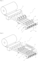
- the device (1) for producing a padding and wedging element comprises a guide means, a drive means and a means for creasing the consumable.
- the device (1) comprises a consumable supply means.
- the guide means is held at least by one holding means magnetic.
- a padding element can also be a cushioning element, making it possible to surround, cushion or even pad the free spaces of a box around the periphery of the item(s) to be packaged.
- the invention relates more precisely to the magnetic holding means of the guide means making it possible to provide a space around the guide means for the free movement of the consumable and the padding and wedging element thus produced by the device (1) , in order to avoid the risk of jamming the consumable.
- a guiding means is intended to support or even to constrain according to a path predetermined by the profile of the guiding means, the consumable as it advances, so that the consumable adapts a predefined conformation prior to its crumpling.
- the invention also relates, in combination with the magnetic holding means, the driving means and/or the crumpling means which are advantageously retractable, in order to also sequentially leave a free space at the periphery of the guide means , with the aim of limiting or even avoiding any risk of jamming the consumable during operation of the device (1).
- the device (1) according to the invention is intended to be powered by at least one consumable.
- the consumable is advantageously presented as a strip or sheet of kraft paper, comprising perforation lines, preferably packaged in a roll or as an accordion-folded strip of paper.
- sheet, strip or consumable will be used to designate the same entity to be creased.
- the consumable is thus brought into contact at least at the level of the driving means and the creasing means along the guide means, during the driving and creasing phases of the consumable.
- the average plane of advancement of the consumable is the plane including the drive axis (Y) and the transverse axis (X).
- the device (1) according to the invention can be positioned horizontally, i.e. the advance of the consumable is directed parallel to the ground, or positioned vertically, i.e. the advance of the consumable is directed downwards perpendicularly or substantially perpendicular to the ground.
- the axis perpendicular to the average plane of advancement of the consumable whatever the positioning of the device (1) will be called vertical axis (Z).
- the guide means comprises a guide body (2) of the consumable, at least one part of which is mechanically secured to at least one constituent element of the device, as explained in more detail in the remainder of the description, while at least another part of the guide body is held by magnetic repulsion forces.
- the guide body extending along the drive axis (Y) requires at least two holding points, in order to be held in position along the drive axis (Y) of the consumable , in view of the adequate functioning of the device according to the invention.
- the two ends of the means of the guide body (2) are free, while at least part of its profile is mechanically secured to a constituent element of the device according to the invention, such as by means of training.
- the mechanical degrees of freedom at a part of the guide body (2), such as one of its ends, are maintained by magnetic repulsion forces at another part of the guide body (2), such as its other free end.
- At least part of the guide body (2) is mechanically secured to a part of the device (1) according to the invention, leaving mechanical degrees of freedom at the aforementioned part of the guide body (2), these degrees of mechanical freedom are maintained by magnetic repulsion forces at another part of the guide body (2).
- the degrees of freedom which are mechanically blocked at a part of a guide body (2) are left free or blocked by magnetic repulsion forces.
- the degrees of freedom in translation along the axes (X, X'), (Y, Y') and (Z, Z') of one end of a guide body (2) are blocked mechanically, while at its other end the degrees of freedom in translation along the axis (Z, Z') are blocked by magnetic repulsion forces.
- the degrees of freedom in translation along the axes (Y, Y') and (Z, Z') and according to the degrees of freedom in rotation are mechanically blocked at one of the ends of a body of guidance (2), while the degrees of freedom in translation along the axes (X, X') and (Z, Z') and the degrees of freedom in rotation are blocked by magnetic repulsion forces.
- the degrees of freedom in translation along the axes (X, of the ends of a guide body (2), while the degrees of freedom in translation along the axis (Y, Y') and the degrees of freedom in rotation along the axis (Z, Z') are blocked by magnetic repulsive forces.
- the degrees of freedom in translation along the axes (X, of the ends of a guide body (2), while the degrees of freedom in translation along the axis (X, X') and the degrees of freedom in rotation along the axis (X, X') are blocked by magnetic repulsive forces.
- the degrees of freedom in translation along the axes (Y, Y') and (Z, Z') and according to the degrees of freedom in rotation are mechanically blocked at one of the ends of a body of guidance (2), while the degrees of freedom in translation along the axis (X, X') and the degrees of freedom in rotation along the axis (Z, Z') are blocked by magnetic repulsion forces.
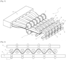
- At least part of the profile of a guide body (2) comprises a permanent magnet (3) or an electromagnet.
- a guide body (2) comprises a permanent magnet (3) at its free end.
- the poles of the permanent magnets (3) are oriented perpendicular to the average plane of advancement of the consumable.
- the poles of the permanent magnets (3) are oriented parallel to the average plane of advancement of the consumable.
- a guide body (2) comprises an electromagnet, for example at its free end or substantially at its free end.
- the device (1) comprises a magnetic holding means around at least part of the periphery of a guide body (2) located opposite at least one permanent magnet (3) or an electromagnet arranged within or on the periphery of at least part of a guide body (2).
- a magnetic holding means a means of holding by magnetic repulsion forces complementary to the permanent magnets or electromagnets located at the level of the guide bodies (2).
- the magnetic holding means is arranged in such a way as to form a space around the part of the guide body (2) arranged in correspondence.
- the magnetic holding means comprises a permanent magnet (3) or an electromagnet.
- the magnetic holding means is presented by a magnetic support (4), for example at least one profile such as a bar or an enclosure, or even two enclosure portions arranged in opposition to each other.
- the magnetic support (4) is represented by a bar comprising, for example, permanent magnets (3) located opposite each of the permanent magnets (3) located on the guide bodies (2).
- the magnetic support (4) is represented by two parallel bars, in which at least part of the profile of the guide bodies (2) are arranged in the space between the two bars, in such a way as to leave a space free between the guide bodies (2) and the bars.
- the poles of the same polarity of the permanent magnets (3) respectively arranged on a guide body (2) and the at least one bar are arranged facing each other.
- This last characteristic makes it possible to maintain the guide bodies throughout the operation of the device (1) according to the invention, while leaving a peripheral space around the guide bodies (2) and advantageously all along their profile and advantageously at at least one of their free ends.
- the magnetic support (4) is a hollow enclosure located on the periphery of at least one guide body (2).
- the magnetic support (4) comprises two enclosure portions arranged in opposition to each other partially surrounding at least one guide body (2).
- At least part of a guide body (2) has a longitudinal profile.
- the guide means comprises a plurality of guide bodies (2) of which at least a part of each of the guide bodies (2) is mechanically secured to at least one constituent element of the device (1), while at least another part of each of the guide bodies (2) is held by magnetic repulsion forces.
- each of the guide bodies (2) is oriented in the same direction, for example, opposite the supply means.
- one end of a guide body (2) is secured to the power supply means, while its other end is free and held by magnetic repulsion forces.
- a free end of the guide body (2) is held by magnetic repulsion forces facing the supply means, while at least a part along its longitudinal profile is mechanically secured to a constituent element of the device (1).
- the end of the guide body (2) located in opposition to the supply means is also free and held by magnetic repulsion forces.
- the end of the guide body (2) arranged opposite the supply means is completely free, namely not mechanically secured nor held by magnetic repulsion forces, while at the same time less a part of the guide body (2) is mechanically secured, for example the central part, for example by the drive means, while the end of the guide body (2) located in opposition to the supply means is maintained by magnetic repulsion forces.
- the end of the guide body (2) arranged opposite the supply means is held by magnetic repulsion forces, while at least part of the guide body ( 2) is mechanically secured, for example the central part, for example by the drive means, while the end of the guide body (2) located in opposition to the supply means is completely free, namely not mechanically secured nor held by magnetic repulsion forces.
- a guide body (2) is in magnetic interaction with the magnetic support (4), but can also be in magnetic interaction, namely in magnetic repulsion with another guide body (2).
- the poles of the permanent magnets (3) of the magnetic support (4) and of the permanent magnets (3) arranged at the guide bodies (2) are oriented along a transverse axis (X), such that a poles of a permanent magnet (3) of a guide body (2) interact with a pole of the same polarity at the magnetic support (4), while the other pole interacts with that of another body of adjacent guide (2).
- the power supply means comprises a shaping block (5), also called a shaper.
- the shaping block (5) comprises at least one opening (6) intended for the passage and shaping of the strip of paper.
- the shaping block (5) of the supply means comprises a rectilinear slot (6) through which a consumable, preferably a strip of paper, is intended to pass.
- the conformation block (5) comprises two parallel lights (6) intended to each be powered by a sheet of paper.
- the conformation block (5) comprises a curved light (6), partially illustrated, which allows the winding of a sheet of paper on itself, namely that the ends of the light (6) overlap the one on top of the other in an offset manner.
- the driving means and the crumpling means can engage permanently or sequentially with the consumable.
- the drive means comprises a set of drive wheels (7) arranged in opposition to the means of advancing the consumable.
- the set of drive wheels (7) are located in an intermediate space between two guide bodies (2).
- the drive means is a translation drive means, intended to operate sequentially.
- the training means illustrated in figure 2 is movable both in translation along the drive axis (Y) and along the vertical axis (Z).
- the aforementioned drive means can be retracted either by translation along the vertical axis (Z) or by pivoting, and in all cases, is movable in translation along the drive axis (Y).
- the consumable is thus made free after the advancing and crumpling sequences both by the drive means and by the crumpling means at the level of the guide means.
- the drive means comprises a drive flap (8), preferably a series of drive flaps (8), mounted movable(s) along a shaft (9) which is movable in rotation, while the shaft (9) is also movable in translation along the drive axis (Y).
- the shaft (9) securing a drive shutter (8) is for example, as illustrated in figure 2 , embedded in a slot oriented parallel to the drive axis (Y) arranged in a plate located perpendicular to the means of advancing the consumable.
- the drive flaps (8) are located between the guide bodies (2), more precisely between the interspaces of the guide bodies (2).
- the drive means comprises a pair of drive flaps (8), more precisely a series of pairs of drive flaps (8), their respective free ends being located opposite one of the other in opposition to the average progress plan of the consumable.
- a drive flap (8) can adapt at least three positions, namely a high rest position in which the drive flap (8) is retracted, the free end of the drive flap (8) not being not in contact with the consumable, as illustrated in figures 1 to 3 , as well as a low contact position of the end free of the drive flap (8) with the consumable by rotating the shaft, followed by a driving position of the consumable by the translation of the shaft (9) along the drive axis ( Y), parallel to the median plane of advancing of the consumable, towards the crumpling means.
- This kinematics also includes the retraction of the drive flaps (8) then their return to their starting position by translation of the shaft (8) towards the supply means.
- the drive means comprises a drive body movable only in translational movements, more preferably comprises a series of drive bodies located directly above the interspaces between pairs of guide bodies (2).
- a drive body is movable along a vertical axis (Z) and along a drive axis (Y).
- a drive body can adopt at least two positions, namely a first contact position, in which the drive body is in contact with the consumable, and a second retracted rest position, the drive body not being in contact with the consumable. contact with the consumable.
- the drive body is intended to follow a kinematics of advancing the consumable, in which the drive body is initially in a second retracted position, then undergoes a vertical translation along a vertical axis (Z) to adopt the first position contact, well undergoes a translation along a drive axis (Y) to advance the consumable towards the crumpling means.
- This kinematics also includes the raising of the drive body then its return to its starting position by translation towards the supply means.
- the drive means comprises a pair of drive bodies, advantageously a series of pairs of drive bodies, their respective free ends being located facing each other in opposition to each other. compared to the average plan to advance the consumable.
- the creasing means according to the invention can be produced by a continuous creasing means in which the creasing means is in permanent contact with the consumable or by a sequential creasing means in which the creasing means perform back and forth movements. comes in a position constraining the consumable and in a position releasing the consumable.
- the creasing means is continuous and produced by a pair of creasing wheels (10).
- way to Crumpling can be considered as a sequential obstruction means, which blocks the advancement of the paper driven by the drive means along the guide means.
- the creasing means can thus adopt at least two positions, a position constraining the consumable, intended to obstruct the advancement of at least one sheet of paper and crease the latter when the consumable is advanced and/or during mobility of the crumpling means in contact with the consumable, to a position no longer constraining the consumable, intended to allow the crumpled paper to advance downstream of the creasing means for its evacuation.
- the position no longer constraining the consumable can leave the advance of the consumable free, at the level of the guiding means, towards its evacuation to avoid the risk of jamming of the consumable both at the level of the drive means and at the level of the crumpling means along the guide body.
- the creasing means is intended to be alternately in a contact position constraining the consumable and a position in which the creasing means is retracted by at least one back and forth movement from the retracted position to the position of creasing as such.
- the position in which the crumpling means does not constrain the advancement of the consumable can be considered as a retracted position or a position for releasing the consumable.
- a withdrawn position namely a position of the creasing means which is no longer in contact with the consumable or a position in contact with the consumable but in a position where the means creasing does not exert force against the consumable, leaving its evacuation free downstream of the creasing means.
- the crumpling means is thus at least movable along a vertical axis (Z) perpendicular to the drive axis (Y) which is parallel to the advancement of the consumable.
- the crumpling means according to the invention is movable along a transverse axis (X) perpendicular to the drive axis (Y).
- the crumpling means is movable along the drive axis (Y).
- the crumpling means is movable along the vertical axis (Z) and along the drive axis (Y).
- the crumpling means is movable along the vertical axis (Z) and along the transverse axis (X).
- the crumpling means is movable along the vertical axis (Z) and both along the transverse axis (X) and along the drive axis (Y).
- the creasing means comprises a creasing flap (11) secured to a shaft (9) or a creasing rod (12).
- the creasing means comprises a creasing flap (11).
- the creasing means comprises a creasing rod (12).
- a creasing flap (11) is movable along a vertical axis (Z) and along a drive axis (Y) in a rotational movement.
- the pivoting of the shaft (9) is advantageously carried out in both directions of rotation.
- the movement of the rotation of a creasing flap (11) allows blocking in a low position, creasing in intermediate positions and/or in the low position in contact with the consumable and release complete the consumable in a completely retracted position or in a consumable release position not constraining the consumable.
- a crumpling flap (11) is movable along a transverse axis (X) in a translational movement.
- a creasing flap (11) is a part pivotally mounted on the shaft (9) or integral with the shaft (9) which is mounted movable in rotation, its free end of which is intended to constrain the consumable at least along the vertical axis (Z).
- the free end of the creasing flap (11) is rounded to avoid damaging the sheet of paper when moving the creasing flap (11) into contact with the consumable.
- a creasing rod (12) is directed in the direction of the consumable and is movable along the vertical axis (Z), advantageously along the drive axis (Y) and advantageously along the transverse axis (X) by translation movements.
- a creasing rod (12) is movable along the vertical axis (Z) and along the drive axis (Y).
- a crumpling rod (12) is movable along the vertical axis (Z) and the transverse axis (X).
- a crumpling rod (12) is both movable along the vertical axis (Z), the drive axis (Y) and the transverse axis (X) by translation movements.
- the creasing means comprises a series of creasing flaps (11) or creasing rods (12) aligned along a transverse axis (X) perpendicular to the drive axis (Y).
- creasing flaps (11) of a series are secured to a shaft (9), while creasing rods (12) of a series are secured for example to a plate (13).
- the shaft (9) securing a series of crumpling flaps (11) is movable in rotation by back and forth movements.
- the shaft (9) is also movable in translation along a transverse axis (X) by back and forth movements.
- the crumpling flaps (11) of a series each follow the same translation movement back and forth along a transverse axis (X).
- a pair of creasing flaps (11) of a series are movable along a transverse axis (X) approaching each other.
- the crumpling flaps (11) of a series are movable two by two by a translation movement approaching along a transverse axis (X).
- each of the creasing flaps (11) or each of the pairs of creasing flaps (11) of a series are movably mounted independently on the shaft (9), at least along the transverse axis (X ) following the tree (9) to which they are attached.
- the crumpling rods (12) are movable within the plate along a transverse axis (X) and along a drive axis (Y), and either along a vertical axis ( Z) or the plate is movable along a vertical axis (Z).
- the creasing rods (11) and the creasing flaps (12) are for example movable in translation by linear motors, not shown.
- the creasing means comprises a plurality of series of creasing flaps (11) or creasing rods (12), mounted on shafts () or parallel plates along the axis of drive (Y).
- This last characteristic makes it possible to simultaneously crease a larger part of the consumable and to harmonize the crease along the consumable in view of a production of padding and cushioning element with greater efficiency.
- the creasing flaps (11) or the creasing rods (12) of a first series are respectively offset along drive axes (Y) relative to those of a second series.
- the creasing flaps (11) or the rods of crumpling (12) of a first series are respectively aligned along drive axes (Y) relative to those of a second series.
- the creasing means can be located on one side of the consumable along the vertical axis (Z) or on either side of the consumable, in opposition or offset according to the average plane of advancement of the consumable, namely the plane including the drive axis (Y) and the transverse axis (X).
- the creasing means is located on either side of the consumable.
- a first series of creasing flaps (11) is located in opposition to a second series of creasing flaps (11), the creasing flaps (11) of each of the series being aligned along a vertical axis (Z).
- each of the shafts (9) securing a series of crumpling flaps (11) is arranged parallel and equidistant from the average plane of advancement of the consumable.
- the creasing flaps (11) or the creasing rods (12) of two adjacent series can work according to creasing sequences, moving closer together or apart from each other.
- the device (1) comprises a control unit directing creasing sequences of the creasing flaps (11) or creasing rods (12) in the same series and pluralities of series relative to each other.
- the device comprises a set of driving wheels (7) and a creasing flap (9), more precisely a series of sets of driving wheels (7) and a series of creasing flaps (9).
- the device (1) comprises a drive flap (8) and a creasing flap (11), more precisely a series of driving flaps (8) and a series of creasing flaps (9).
- the device (1) comprises a set of driving wheels (7) and a creasing flap (9), more precisely a series of sets of driving wheels (7) and two series of creasing flaps (9) .
- the device (1) comprises a set of driving wheels (7) and a creasing rod (12), more precisely a series of driving wheels (7) and a series of creasing rods (12).
Landscapes
- Folding Of Thin Sheet-Like Materials, Special Discharging Devices, And Others (AREA)
- Feeding Of Articles By Means Other Than Belts Or Rollers (AREA)
- Magnetic Treatment Devices (AREA)
Claims (10)
- Vorrichtung (1) zur Herstellung eines Polsterprodukts mit einem Mittel zur Führung von Verbrauchsmaterial, einem Mittel zum Antrieb des Verbrauchsmaterials entlang einer Antriebsachse (Y), einem Mittel zum Knautschen des Verbrauchsmaterials, wobei das Mittel zur Führung an einem Teil der Vorrichtung (1) einerseits mechanisch an mindestens einem Teil seines Profils befestigt ist, dadurch gekennzeichnet, dass andererseits das Mittel zur Führung an einem anderen Teil der Vorrichtung (1) durch magnetische Abstoßungskräfte an mindestens einem anderen Teil seines Profils gehalten wird.
- Vorrichtung (1) nach Anspruch 1, dadurch gekennzeichnet, dass der durch magnetische Abstoßungskräfte gehaltene Teil des Profils des Mittels zur Führungs an einer magnetischen Halterung (4) gehalten wird, so dass ein Spalt zwischen dem Mittel zur Führung und der magnetischen Halterung (4) gebildet wird.
- Vorrichtung (1) nach dem vorhergehenden Anspruch, dadurch gekennzeichnet, dass das Mittel zur Führung und die magnetische Halterung (4) jeweils einen Permanentmagneten (3) und/oder einen Elektromagneten umfassen, die paarweise gegenüberliegend angeordnet sind.
- Vorrichtung (1) nach Anspruch 2 oder 3, dadurch gekennzeichnet, dass das Ende oder im Wesentlichen das Ende des Mittels zur Führung frei ist und durch magnetische Abstoßungskräfte an der magnetischen Halterung (4) gehalten wird.
- Vorrichtung (1) nach einem der Ansprüche 2 bis 4, dadurch gekennzeichnet, dass die magnetische Halterung (4) einen Stab oder zwei Stäbe umfasst, die auf beiden Seiten des Mittels zur Führung gegenüberliegend angeordnet sind.
- Vorrichtung (1) nach einem der Ansprüche 2 bis 4, dadurch gekennzeichnet, dass der magnetische Träger (4) eine Umhüllung oder einen Teil einer Umhüllung umfasst, die bzw. der einen Teil des Mittels zur Führung umgibt.
- Vorrichtung (1) nach einem der vorhergehenden Ansprüche, dadurch gekennzeichnet, dass das Mittel zur Führung mechanisch an einen Formblock (5) als Zuführungsmittel befestigt ist, der stromaufwärts des Mittels zum Antrieb angeordnet ist.
- Vorrichtung (1) nach dem vorhergehenden Anspruch, dadurch gekennzeichnet, dass der Formblock (5) zwei Öffnungen umfasst, die dazu bestimmt sind, jeweils Verbrauchsmaterial aufzunehmen, oder eine Öffnung mit überlappenden Enden, die dazu bestimmt ist, ein auf sich selbst gefaltetes Verbrauchsmaterial aufzunehmen.
- Vorrichtung (1) nach dem vorhergehenden Anspruch, dadurch gekennzeichnet, dass das Mittel zur Führung mechanisch zwischen den beiden Öffnungen oder in der Öffnung, deren Enden sich überlappen, befestigt ist.
- Vorrichtung (1) nach einem der Ansprüche 1 bis 6, dadurch gekennzeichnet, dass mindestens ein Teil des Profils des Mittels zur Führung mechanisch an dem Mittel zum Knautschen oder dem Mittel zum Antrieb befestigt ist.
Applications Claiming Priority (2)
| Application Number | Priority Date | Filing Date | Title |
|---|---|---|---|
| FR1910260A FR3100742B1 (fr) | 2019-09-17 | 2019-09-17 | Dispositif de production d’element de calage |
| PCT/EP2020/075951 WO2021053061A1 (fr) | 2019-09-17 | 2020-09-17 | Dispositif de production d'element de calage |
Publications (3)
| Publication Number | Publication Date |
|---|---|
| EP4031360A1 EP4031360A1 (de) | 2022-07-27 |
| EP4031360B1 true EP4031360B1 (de) | 2023-11-15 |
| EP4031360C0 EP4031360C0 (de) | 2023-11-15 |
Family
ID=68807130
Family Applications (1)
| Application Number | Title | Priority Date | Filing Date |
|---|---|---|---|
| EP20785917.4A Active EP4031360B1 (de) | 2019-09-17 | 2020-09-17 | Vorrichtung zum produzieren von polsterelementen |
Country Status (4)
| Country | Link |
|---|---|
| US (1) | US11993053B2 (de) |
| EP (1) | EP4031360B1 (de) |
| FR (1) | FR3100742B1 (de) |
| WO (1) | WO2021053061A1 (de) |
Family Cites Families (11)
| Publication number | Priority date | Publication date | Assignee | Title |
|---|---|---|---|---|
| US4717613A (en) * | 1984-05-10 | 1988-01-05 | Ranpak Corporation | Mechanism and method for producing cushioning dunnage |
| AU2989899A (en) * | 1998-03-18 | 1999-10-11 | United Container Machinery, Inc. | Lengthwise web corrugator |
| DE19858537A1 (de) * | 1998-12-18 | 2000-06-21 | Lindner Jun | Verfahren und Vorrichtung zum Herstellen eines Papierpolsters aus einer einlagigen Papierbahn |
| DE10242998B4 (de) * | 2002-09-17 | 2004-07-22 | Storopack Hans Reichenecker Gmbh | Polster aus Papier, sowie Verfahren und Vorrichtung zu dessen Herstellung |
| EP1789252B1 (de) * | 2004-06-25 | 2008-01-02 | Ranpak Corp. | Packmaterialumwandlungsmaschine mit gleitenden führungen |
| DE102006059638A1 (de) * | 2006-12-18 | 2008-06-19 | Pack-Tiger Gmbh | Maschine zur Herstellung von Papier-Polstern |
| US9427928B2 (en) * | 2009-08-25 | 2016-08-30 | Sealed Air Corporation (Us) | Method and machine for producing packaging cushioning |
| EP2704969B1 (de) * | 2011-05-03 | 2015-06-24 | Tetra Laval Holdings & Finance S.A. | Teiler zur unterteilung von produkten in parallelreihen |
| DE102012222805B3 (de) * | 2012-12-11 | 2013-06-06 | Storopack Hans Reichenecker Gmbh | Verfahren und Vorrichtung zum Herstellen eines Polsterungserzeugnisses sowie Polsterungserzeugnis |
| GB2508267B (en) * | 2013-09-16 | 2015-01-07 | Dan Steedman | Packaging material forming apparatus, and method of using the same |
| FR3061072B1 (fr) * | 2016-12-22 | 2020-02-07 | Jacky Peterlini | Dispositif de distribution d'element de calage et d'emballage |
-
2019
- 2019-09-17 FR FR1910260A patent/FR3100742B1/fr active Active
-
2020
- 2020-09-17 US US17/761,085 patent/US11993053B2/en active Active
- 2020-09-17 EP EP20785917.4A patent/EP4031360B1/de active Active
- 2020-09-17 WO PCT/EP2020/075951 patent/WO2021053061A1/fr not_active Ceased
Also Published As
| Publication number | Publication date |
|---|---|
| WO2021053061A1 (fr) | 2021-03-25 |
| US11993053B2 (en) | 2024-05-28 |
| FR3100742A1 (fr) | 2021-03-19 |
| US20220339902A1 (en) | 2022-10-27 |
| EP4031360C0 (de) | 2023-11-15 |
| EP4031360A1 (de) | 2022-07-27 |
| FR3100742B1 (fr) | 2021-08-06 |
Similar Documents
| Publication | Publication Date | Title |
|---|---|---|
| DE69213852T2 (de) | Vorrichtung zum Herstellen von Füllmaterial aus Bahnmaterial | |
| EP2616243B1 (de) | Vorrichtung zum drucken durch stanzen | |
| EP0555709B1 (de) | Tragrahmen zum zeitweiligen Abstützen von horizontalen Scheiben während des Stapelns | |
| EP2694280B1 (de) | Druckvorrichtung für heissprägen | |
| WO2010037475A1 (fr) | Dispositif de transport et de pliage de decoupes | |
| EP2867007B1 (de) | Vorrichtung zum schneiden und übertragen einer materialbahn zum zusammenbau eines reifens | |
| CA3046402A1 (fr) | Dispositif de distribution d'element de calage et d'emballage, procede de production, element de calage et consommable pour sa production | |
| EP2860117B1 (de) | Maschine zum Einfüllen von Lebensmittelprodukten in Beutel, und Verfahren zum Einfüllen von Lebensmittelprodukten in Beutel | |
| EP4031360B1 (de) | Vorrichtung zum produzieren von polsterelementen | |
| EP3414199A1 (de) | Einlageblattladevorrichtung, zuschnittaufnahmestation, maschine zur verarbeitung von blattförmigen elementen und einlageblatttransportverfahren | |
| WO2014202308A1 (de) | Vorrichtung und verfahren zur bildung von verpackungseinheiten | |
| EP2196293B1 (de) | Schneidvorrichtung für Dekor für kegelförmige Träger und Vorrichtung zur Herstellung von kegelförmigen Trägern mit Dekoreinlage mit einer solchen Schneidvorrichtung | |
| KR101202869B1 (ko) | 비닐원단 자동 권취장치 및 이를 포함하는 롤백 제조장치 | |
| EP1982937B1 (de) | Transportvorrichtung für eine Leim- und Faltmaschine | |
| JP2011073758A (ja) | 包装装置 | |
| KR102390815B1 (ko) | 그립퍼를 갖춘 이송장치 | |
| EP0876904B1 (de) | Wendevorrichtung für eine Frontplatte in einer Falt-Beleimungsvorrichtung | |
| FR3100743A1 (fr) | Dispositif de production d’element de calage | |
| WO2018069614A1 (fr) | Procede et dispositif de mise en forme d'un flan autour d'un mandrin | |
| ITVR980056A1 (it) | Macchina formatrice per nastri metallici, in particolare per la realiz zazione di piatre per accumulatori elettrici | |
| CH359593A (fr) | Dispositif permettant d'intercepter en cours de distribution des feuilles déposées une à une en pile | |
| KR20130142050A (ko) | 비닐원단 자동 권취장치 및 이를 포함하는 롤백 제조장치 | |
| BE336141A (de) | ||
| DE202010007070U1 (de) | Vorrichtung zum Verpacken von Gegenständen | |
| BE673902A (de) |
Legal Events
| Date | Code | Title | Description |
|---|---|---|---|
| STAA | Information on the status of an ep patent application or granted ep patent |
Free format text: STATUS: UNKNOWN |
|
| STAA | Information on the status of an ep patent application or granted ep patent |
Free format text: STATUS: THE INTERNATIONAL PUBLICATION HAS BEEN MADE |
|
| PUAI | Public reference made under article 153(3) epc to a published international application that has entered the european phase |
Free format text: ORIGINAL CODE: 0009012 |
|
| STAA | Information on the status of an ep patent application or granted ep patent |
Free format text: STATUS: REQUEST FOR EXAMINATION WAS MADE |
|
| 17P | Request for examination filed |
Effective date: 20220315 |
|
| AK | Designated contracting states |
Kind code of ref document: A1 Designated state(s): AL AT BE BG CH CY CZ DE DK EE ES FI FR GB GR HR HU IE IS IT LI LT LU LV MC MK MT NL NO PL PT RO RS SE SI SK SM TR |
|
| DAV | Request for validation of the european patent (deleted) | ||
| DAX | Request for extension of the european patent (deleted) | ||
| GRAP | Despatch of communication of intention to grant a patent |
Free format text: ORIGINAL CODE: EPIDOSNIGR1 |
|
| STAA | Information on the status of an ep patent application or granted ep patent |
Free format text: STATUS: GRANT OF PATENT IS INTENDED |
|
| INTG | Intention to grant announced |
Effective date: 20230612 |
|
| GRAS | Grant fee paid |
Free format text: ORIGINAL CODE: EPIDOSNIGR3 |
|
| GRAA | (expected) grant |
Free format text: ORIGINAL CODE: 0009210 |
|
| STAA | Information on the status of an ep patent application or granted ep patent |
Free format text: STATUS: THE PATENT HAS BEEN GRANTED |
|
| AK | Designated contracting states |
Kind code of ref document: B1 Designated state(s): AL AT BE BG CH CY CZ DE DK EE ES FI FR GB GR HR HU IE IS IT LI LT LU LV MC MK MT NL NO PL PT RO RS SE SI SK SM TR |
|
| REG | Reference to a national code |
Ref country code: CH Ref legal event code: EP Ref country code: GB Ref legal event code: FG4D Free format text: NOT ENGLISH |
|
| REG | Reference to a national code |
Ref country code: DE Ref legal event code: R096 Ref document number: 602020021188 Country of ref document: DE |
|
| REG | Reference to a national code |
Ref country code: IE Ref legal event code: FG4D Free format text: LANGUAGE OF EP DOCUMENT: FRENCH |
|
| U01 | Request for unitary effect filed |
Effective date: 20231205 |
|
| U07 | Unitary effect registered |
Designated state(s): AT BE BG DE DK EE FI FR IT LT LU LV MT NL PT SE SI Effective date: 20231213 |
|
| PG25 | Lapsed in a contracting state [announced via postgrant information from national office to epo] |
Ref country code: GR Free format text: LAPSE BECAUSE OF FAILURE TO SUBMIT A TRANSLATION OF THE DESCRIPTION OR TO PAY THE FEE WITHIN THE PRESCRIBED TIME-LIMIT Effective date: 20240216 |
|
| PG25 | Lapsed in a contracting state [announced via postgrant information from national office to epo] |
Ref country code: IS Free format text: LAPSE BECAUSE OF FAILURE TO SUBMIT A TRANSLATION OF THE DESCRIPTION OR TO PAY THE FEE WITHIN THE PRESCRIBED TIME-LIMIT Effective date: 20240315 |
|
| PG25 | Lapsed in a contracting state [announced via postgrant information from national office to epo] |
Ref country code: ES Free format text: LAPSE BECAUSE OF FAILURE TO SUBMIT A TRANSLATION OF THE DESCRIPTION OR TO PAY THE FEE WITHIN THE PRESCRIBED TIME-LIMIT Effective date: 20231115 |
|
| PG25 | Lapsed in a contracting state [announced via postgrant information from national office to epo] |
Ref country code: IS Free format text: LAPSE BECAUSE OF FAILURE TO SUBMIT A TRANSLATION OF THE DESCRIPTION OR TO PAY THE FEE WITHIN THE PRESCRIBED TIME-LIMIT Effective date: 20240315 Ref country code: GR Free format text: LAPSE BECAUSE OF FAILURE TO SUBMIT A TRANSLATION OF THE DESCRIPTION OR TO PAY THE FEE WITHIN THE PRESCRIBED TIME-LIMIT Effective date: 20240216 Ref country code: ES Free format text: LAPSE BECAUSE OF FAILURE TO SUBMIT A TRANSLATION OF THE DESCRIPTION OR TO PAY THE FEE WITHIN THE PRESCRIBED TIME-LIMIT Effective date: 20231115 |
|
| PG25 | Lapsed in a contracting state [announced via postgrant information from national office to epo] |
Ref country code: RS Free format text: LAPSE BECAUSE OF FAILURE TO SUBMIT A TRANSLATION OF THE DESCRIPTION OR TO PAY THE FEE WITHIN THE PRESCRIBED TIME-LIMIT Effective date: 20231115 Ref country code: PL Free format text: LAPSE BECAUSE OF FAILURE TO SUBMIT A TRANSLATION OF THE DESCRIPTION OR TO PAY THE FEE WITHIN THE PRESCRIBED TIME-LIMIT Effective date: 20231115 Ref country code: NO Free format text: LAPSE BECAUSE OF FAILURE TO SUBMIT A TRANSLATION OF THE DESCRIPTION OR TO PAY THE FEE WITHIN THE PRESCRIBED TIME-LIMIT Effective date: 20240215 Ref country code: HR Free format text: LAPSE BECAUSE OF FAILURE TO SUBMIT A TRANSLATION OF THE DESCRIPTION OR TO PAY THE FEE WITHIN THE PRESCRIBED TIME-LIMIT Effective date: 20231115 |
|
| PG25 | Lapsed in a contracting state [announced via postgrant information from national office to epo] |
Ref country code: CZ Free format text: LAPSE BECAUSE OF FAILURE TO SUBMIT A TRANSLATION OF THE DESCRIPTION OR TO PAY THE FEE WITHIN THE PRESCRIBED TIME-LIMIT Effective date: 20231115 |
|
| PG25 | Lapsed in a contracting state [announced via postgrant information from national office to epo] |
Ref country code: SK Free format text: LAPSE BECAUSE OF FAILURE TO SUBMIT A TRANSLATION OF THE DESCRIPTION OR TO PAY THE FEE WITHIN THE PRESCRIBED TIME-LIMIT Effective date: 20231115 |
|
| PG25 | Lapsed in a contracting state [announced via postgrant information from national office to epo] |
Ref country code: SM Free format text: LAPSE BECAUSE OF FAILURE TO SUBMIT A TRANSLATION OF THE DESCRIPTION OR TO PAY THE FEE WITHIN THE PRESCRIBED TIME-LIMIT Effective date: 20231115 Ref country code: SK Free format text: LAPSE BECAUSE OF FAILURE TO SUBMIT A TRANSLATION OF THE DESCRIPTION OR TO PAY THE FEE WITHIN THE PRESCRIBED TIME-LIMIT Effective date: 20231115 Ref country code: RO Free format text: LAPSE BECAUSE OF FAILURE TO SUBMIT A TRANSLATION OF THE DESCRIPTION OR TO PAY THE FEE WITHIN THE PRESCRIBED TIME-LIMIT Effective date: 20231115 Ref country code: CZ Free format text: LAPSE BECAUSE OF FAILURE TO SUBMIT A TRANSLATION OF THE DESCRIPTION OR TO PAY THE FEE WITHIN THE PRESCRIBED TIME-LIMIT Effective date: 20231115 |
|
| REG | Reference to a national code |
Ref country code: DE Ref legal event code: R097 Ref document number: 602020021188 Country of ref document: DE |
|
| PLBE | No opposition filed within time limit |
Free format text: ORIGINAL CODE: 0009261 |
|
| STAA | Information on the status of an ep patent application or granted ep patent |
Free format text: STATUS: NO OPPOSITION FILED WITHIN TIME LIMIT |
|
| 26N | No opposition filed |
Effective date: 20240819 |
|
| U20 | Renewal fee for the european patent with unitary effect paid |
Year of fee payment: 5 Effective date: 20240924 |
|
| U1N | Appointed representative for the unitary patent procedure changed after the registration of the unitary effect |
Representative=s name: KATZAROV S.A.; CH |
|
| PG25 | Lapsed in a contracting state [announced via postgrant information from national office to epo] |
Ref country code: MC Free format text: LAPSE BECAUSE OF FAILURE TO SUBMIT A TRANSLATION OF THE DESCRIPTION OR TO PAY THE FEE WITHIN THE PRESCRIBED TIME-LIMIT Effective date: 20231115 |
|
| GBPC | Gb: european patent ceased through non-payment of renewal fee |
Effective date: 20240917 |
|
| PG25 | Lapsed in a contracting state [announced via postgrant information from national office to epo] |
Ref country code: GB Free format text: LAPSE BECAUSE OF NON-PAYMENT OF DUE FEES Effective date: 20240917 |
|
| PG25 | Lapsed in a contracting state [announced via postgrant information from national office to epo] |
Ref country code: IE Free format text: LAPSE BECAUSE OF NON-PAYMENT OF DUE FEES Effective date: 20240917 |
|
| REG | Reference to a national code |
Ref country code: CH Ref legal event code: U11 Free format text: ST27 STATUS EVENT CODE: U-0-0-U10-U11 (AS PROVIDED BY THE NATIONAL OFFICE) Effective date: 20251001 |
|
| U20 | Renewal fee for the european patent with unitary effect paid |
Year of fee payment: 6 Effective date: 20250826 |
|
| PGFP | Annual fee paid to national office [announced via postgrant information from national office to epo] |
Ref country code: CH Payment date: 20251001 Year of fee payment: 6 |
|
| PG25 | Lapsed in a contracting state [announced via postgrant information from national office to epo] |
Ref country code: CY Free format text: LAPSE BECAUSE OF FAILURE TO SUBMIT A TRANSLATION OF THE DESCRIPTION OR TO PAY THE FEE WITHIN THE PRESCRIBED TIME-LIMIT; INVALID AB INITIO Effective date: 20200917 |
|
| PG25 | Lapsed in a contracting state [announced via postgrant information from national office to epo] |
Ref country code: HU Free format text: LAPSE BECAUSE OF FAILURE TO SUBMIT A TRANSLATION OF THE DESCRIPTION OR TO PAY THE FEE WITHIN THE PRESCRIBED TIME-LIMIT; INVALID AB INITIO Effective date: 20200917 |