EP1982937B1 - Transportvorrichtung für eine Leim- und Faltmaschine - Google Patents
Transportvorrichtung für eine Leim- und Faltmaschine Download PDFInfo
- Publication number
- EP1982937B1 EP1982937B1 EP08006790A EP08006790A EP1982937B1 EP 1982937 B1 EP1982937 B1 EP 1982937B1 EP 08006790 A EP08006790 A EP 08006790A EP 08006790 A EP08006790 A EP 08006790A EP 1982937 B1 EP1982937 B1 EP 1982937B1
- Authority
- EP
- European Patent Office
- Prior art keywords
- transport device
- drive shaft
- shaft
- longitudinal
- web
- Prior art date
- Legal status (The legal status is an assumption and is not a legal conclusion. Google has not performed a legal analysis and makes no representation as to the accuracy of the status listed.)
- Active
Links
Images

Classifications
-
- B—PERFORMING OPERATIONS; TRANSPORTING
- B65—CONVEYING; PACKING; STORING; HANDLING THIN OR FILAMENTARY MATERIAL
- B65H—HANDLING THIN OR FILAMENTARY MATERIAL, e.g. SHEETS, WEBS, CABLES
- B65H5/00—Feeding articles separated from piles; Feeding articles to machines
- B65H5/02—Feeding articles separated from piles; Feeding articles to machines by belts or chains, e.g. between belts or chains
- B65H5/021—Feeding articles separated from piles; Feeding articles to machines by belts or chains, e.g. between belts or chains by belts
- B65H5/023—Feeding articles separated from piles; Feeding articles to machines by belts or chains, e.g. between belts or chains by belts between a pair of belts forming a transport nip
-
- B—PERFORMING OPERATIONS; TRANSPORTING
- B65—CONVEYING; PACKING; STORING; HANDLING THIN OR FILAMENTARY MATERIAL
- B65H—HANDLING THIN OR FILAMENTARY MATERIAL, e.g. SHEETS, WEBS, CABLES
- B65H2403/00—Power transmission; Driving means
- B65H2403/50—Driving mechanisms
- B65H2403/52—Translation screw-thread mechanisms
-
- B—PERFORMING OPERATIONS; TRANSPORTING
- B65—CONVEYING; PACKING; STORING; HANDLING THIN OR FILAMENTARY MATERIAL
- B65H—HANDLING THIN OR FILAMENTARY MATERIAL, e.g. SHEETS, WEBS, CABLES
- B65H2407/00—Means not provided for in groups B65H2220/00 – B65H2406/00 specially adapted for particular purposes
- B65H2407/10—Safety means, e.g. for preventing injuries or illegal operations
-
- B—PERFORMING OPERATIONS; TRANSPORTING
- B65—CONVEYING; PACKING; STORING; HANDLING THIN OR FILAMENTARY MATERIAL
- B65H—HANDLING THIN OR FILAMENTARY MATERIAL, e.g. SHEETS, WEBS, CABLES
- B65H2511/00—Dimensions; Position; Numbers; Identification; Occurrences
- B65H2511/10—Size; Dimensions
-
- B—PERFORMING OPERATIONS; TRANSPORTING
- B65—CONVEYING; PACKING; STORING; HANDLING THIN OR FILAMENTARY MATERIAL
- B65H—HANDLING THIN OR FILAMENTARY MATERIAL, e.g. SHEETS, WEBS, CABLES
- B65H2511/00—Dimensions; Position; Numbers; Identification; Occurrences
- B65H2511/20—Location in space
-
- B—PERFORMING OPERATIONS; TRANSPORTING
- B65—CONVEYING; PACKING; STORING; HANDLING THIN OR FILAMENTARY MATERIAL
- B65H—HANDLING THIN OR FILAMENTARY MATERIAL, e.g. SHEETS, WEBS, CABLES
- B65H2701/00—Handled material; Storage means
- B65H2701/10—Handled articles or webs
- B65H2701/17—Nature of material
- B65H2701/176—Cardboard
- B65H2701/1764—Cut-out, single-layer, e.g. flat blanks for boxes
-
- B—PERFORMING OPERATIONS; TRANSPORTING
- B65—CONVEYING; PACKING; STORING; HANDLING THIN OR FILAMENTARY MATERIAL
- B65H—HANDLING THIN OR FILAMENTARY MATERIAL, e.g. SHEETS, WEBS, CABLES
- B65H2801/00—Application field
- B65H2801/81—Packaging machines
Definitions
- the present invention relates to a device for transporting plate elements of low specific mass, paper or cardboard, within a folder-gluer machine; machine commonly used in the packaging industry for making, for example, cardboard boxes.
- a folder-gluer machine comprises a series of modules and stations whose number varies according to the complexity of the manufacturing operations that requires the type of box chosen.
- Such machines generally consist of a feeder supplying the production of cut-out boxes from a stack, an alignment module, a breaker pre-crushing the first and third folds between 90 ° and 180 °, a module of folders with hooks which bend at 180 ° the front legs and the rear legs of the cut, a gluing station, a folder for folding the 2nd and 4th folds of the cut, a presser that compresses the 2nd and 4th folds and deposits the boxes in sheet, and finally a receiving module that receives the boxes while keeping them pressed to allow the glue to dry.
- the conveyance of the blanks from one station to another is carried out by means of belt conveyors which, by friction, grip the cuts between a lower conveyor and an upper conveyor.
- the lower conveyor is provided with lower belts and the upper carrier is provided with either upper belts or upper support rollers.
- the lower conveyor comprises two or more longitudinal longitudinal members each supporting an endless conveyor belt guided by pulleys and rollers.
- Each spar is mounted laterally sliding through bearings along one or more slideways mounted fixed between two longitudinal frames.
- the lateral displacement of each beam is ensured by one or more parallel screws mounted in rotation between the frames, the threaded portions of the screws being respectively engaged in transverse threaded orifices of the longitudinal members.
- the drive of the endless conveyor belt is provided by a drive shaft rotatably mounted between the frames and engaged in a pulley of the spar, called driving pulley.
- the drive shaft is connected by a drive train to an electric motor, so when the motor is running, the shaft is rotated.
- the drive shaft is in the form of a metal bar of polygonal section, for example hexagonal, cooperating form with a transverse orifice formed in the axis of the drive pulley.
- a spar moves laterally under the action of the adjusting screws, it slides along the slideways and along the drive shaft.
- the power required to work and to cause the cuts in the machine depends on the width of the machine.
- the larger the machine the greater the forces to be transmitted, which makes it necessary to increase the torsional resistance of the shaft, for example by increasing its section.
- the drive shaft should be designed only to withstand torsion since the weight of the rails is supported by the slides movement but in practice we see that machine operators do not hesitate to climb on the drive shaft to access certain parts of the machine. Therefore, to prevent the drive shaft from bending, it is also designed to support the weight of a man without bending, which increases the cost of manufacturing the tree.
- a sleeve is generally in the form of a volute spring whose end is secured to a frame and whose other end is secured to a spar, the lateral displacement of the spar causing the extension or compression of the spring . It is easy to understand that the presence of such a spring requires dimension the strut moving screws accordingly. Indeed, the greater the stiffness of the volute spring is important and the torque to exert on the screws to move the side members must be important, which also involves adjusting the electric power of the motors for rotating the screws.
- An object of the present invention is to overcome the aforementioned drawbacks by proposing a transport device that no longer requires a flex-resistant drive shaft and no longer requires protective sleeves.
- the subject of the invention is a transport device according to claim 1.
- the drive shaft is designed to withstand only twisting, which can significantly reduce its dimensions and therefore its mass. Therefore, less material is needed to make the tree, which reduces its manufacturing cost and its size.
- the drive shaft is no longer exposed to the driver of the machine which allows to remove the protective sleeves. Therefore, the dimensions of the screws and those of the electric motors for rotating said screws can be reduced.
- Another advantage of the invention is also to facilitate the maintenance of the machine and to increase the service life of the parts. Indeed, thanks to the invention, the drive shaft, the displacement screws and the movement slides are protected against all kinds of deposit or projection such as dust or glue when the transport device according to the invention. invention is in the sizing station.
- the figure 1 illustrates a lower carrier 1 according to the state of the art.
- the arrow 8 indicates the running direction of the plate elements.
- Such a conveyor generally comprises two longitudinal frames 1a, 1b parallel and distant from each other. Each frame has two large faces: an inner face and an outer face, the inner face of a frame being turned towards the inner face of the other frame.
- the frame 1a is located on the opposite side to the conductor and the frame 1b is located on the driver's side.
- Between the two frames 1 a, 1 b are arranged transversely two parallel cylindrical displacement slides 2, three pairs of parallel displacement screws 3 and a drive shaft 4.
- the displacement slides 2 are embedded at each of their ends to the racks.
- each longitudinal spar is movable transversely between the frames 1 a, 1 b, along the slideways 2, this depending on the size of the blanks to be treated.
- Bearing devices cutouts against the conveyor belts 7 are arranged above certain portions of the longitudinal members 6a, 6b, 6c. These support devices may consist of a series of rollers held down by springs or an endless belt whose lower strand is pressed downwards.
- each spar is controlled by a pair of parallel screws 3 whose threaded portions are respectively engaged in transverse threaded holes of the spar, which screws are fixed in translation but free in rotation between the frames 1 a, 1 b.
- one or more electric motors are provided (not shown).
- Each endless conveyor belt 7 is supported by rollers and a drive pulley 5.
- the drive pulleys 5 are coaxial and rotatably mounted on their respective spars.
- the drive shaft 4 is rotatably mounted between the frames 1a, 1b and engaged in the drive pulleys 5.
- the shaft 4 has a hexagonal section in cooperation of shape with a transverse orifice formed in the axis of each drive pulley 5.
- each sleeve 4a, 4b is in the form of a volute spring recessed at both ends.
- the COC sleeve, noted 4a has one end secured to the frame 1a and the other end secured to the spar 6a, that is to say the spar closest to the frame 1a.
- the sleeve CC, noted 4b has one end secured to the frame 1b and the other end secured to the spar 6b, that is to say the spar closest to the frame 1b.
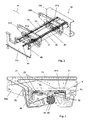
- the Figures 2 and 3 illustrate a lower conveyor 10 according to the invention.
- the arrow 8 indicates the running direction of the plate elements.
- This carrier comprises two frames 10a, 10b parallel and distant from each other. Between the frames 10a, 10b are arranged two longitudinal longitudinal members 60a, 60b. Each spar 60a, 60b is mounted in sliding connection on a pair of common displacement rails 20 integral with a U-shaped profile 9.
- the profile 9 extends transversely between the two frames 10a, 10b, each end of the profile 9 being embedded in a respective frame 10a, 10b.
- the core 9a of the profile is horizontal while the wings 9b, 9c are vertical and turned downwards of the machine.
- the pair of slide rails 20 is mounted on the web of the profile 9 inside the U and extends transversely between the two frames 10a, 10b.
- Each slider 20 is a linear guide rail which, in cross section, has a biconcave shape such that a first concavity faces forward and a second concavity is turned towards the rear of the machine (see FIG. figure 3 ).
- Each spar 60a, 60b has a respective opening 61a, 61b U-shaped in which the profile 9 can pass without interaction.
- each spar is also provided with a pair of pads 21 in shape cooperation with the pair of sliding rails 20.
- each pad 21 of a spar 60a, 60b presents in cross section a U-shaped with a horizontal core and two vertical wings turned upwards the machine such that each wing has in cross section a convexity turned towards the inside of the U so that the convexities of a shoe 21 cooperate with the concavities of a displacement slide 20 to form a slide connection.
- Each spar 60a, 60b supports rollers (not shown), part of which defines a horizontal hard plane 71 for guiding an endless conveyor belt 70.
- the driving of the belt 70 is provided by a driving pulley 50, which is driven by rotation by a drive shaft 40 of hexagonal section.
- Each pulley 50 is mounted in sliding connection with the drive shaft 40.
- the drive shaft 40 extends transversely between the two frames 10a, 10b, each end of the shaft 40 being mounted free to rotate in a respective frame 10a, 10b.
- One of the ends 41 of the shaft 40 passes through the frame 10a to be secured to an electric motor (not shown).
- the shaft 40 is located at least partly between the wings 9b and 9c of the section 9, under the core 9a.
- the drive shaft 40 is no longer apparent as in the state of the art, therefore, the driver of the machine can not interact with the shaft 40, not even between them.
- longitudinal members 60a, 60b since the shaft is protected along its entire length.
- traditional protective sleeves are no longer needed.
- the section 9 being designed to support the weight of the machine operator without bending, the shaft 40 has a lighter structure than in the state of the art. In practice, for a given machine width, it is possible to reduce the section of the drive shaft by at least 30%, thereby reducing the cost of manufacture and the size of the shaft.
- a pair of parallel displacement screws 30 are also provided for moving the respective longitudinal members 60a, 60b along the movement slides 20.
- the threaded part of each screw 30 is engaged in a transverse tapped hole of a respective spar so as to form a helical connection between said screw 30 and said spar, each screw being fixed in translation and free in rotation between the frames 1 a, 1 b.
- one or more electric motors are provided (not shown).
- the displacement screws 30 are located at least partly between the wings 9b and 9c of the profile 9, under the core 9a.
- the lower conveyor is generally surmounted by an upper belt conveyor facilitating the conveying of the cuts taken between the belts of the lower and upper conveyors.
- the invention also applies to the upper conveyor.
Landscapes
- Engineering & Computer Science (AREA)
- Mechanical Engineering (AREA)
- Making Paper Articles (AREA)
- Structure Of Belt Conveyors (AREA)
- Auxiliary Devices For And Details Of Packaging Control (AREA)
- Coating Apparatus (AREA)
- Closing Of Containers (AREA)
Claims (13)
- Transportvorrichtung (10) zum Transport von Blattelementen innerhalb einer Faltklebemaschine, umfassend zwei Längsrahmen (10a, 10b), zwischen denen- eine oder mehrere Gleitschienen (20),- eine oder mehrere Schiebespindeln (30) und eine Antriebswelle (40),- mindestens ein Längstransportträger (60a, 60b), der mindestens ein endloses Förderband (70) unterstützt, wobei der Längstransportträger (60a, 60b) in gleitender Verbindung auf den Gleitschienen (20) und der Antriebswelle (40) und in schraubenartiger Verbindung an den Schiebespindeln (30) befestigt ist,- und Mittel zum Schutz der Antriebswelle (40)positioniert sind,
dadurch gekennzeichnet, dass die Schutzmittel die zwei Längsrahmen (10a, 10b) transversal verbinden. - Transportvorrichtung nach Anspruch 1,
dadurch gekennzeichnet, dass wenigstens eine der Gleitschienen (20) an den Schutzmitteln befestigt ist. - Transportvorrichtung nach Anspruch 2,
dadurch gekennzeichnet, dass die Schutzmittel ein Profil (9) umfassen. - Transportvorrichtung nach Anspruch 3,
dadurch gekennzeichnet, dass das Profil (9) eine zur Antriebswelle (40) hin gerichtete Vertiefung aufweist und in der wenigstens ein Teil der Welle untergebracht ist. - Transportvorrichtung nach Anspruch 3 oder 4,
dadurch gekennzeichnet, dass das Profil (9) im Querschnitt einen Steg (9a) und wenigstens einen Flügel (9b, 9c) aufweist. - Transportvorrichtung nach Anspruch 3 oder 4,
dadurch gekennzeichnet, dass das Profil (9) im Querschnitt einen Steg (9a) und wenigstens zwei Flügel, (9b, 9c) aufweist. - Transportvorrichtung nach Anspruch 6,
dadurch gekennzeichnet, dass die Antriebswelle (40) sich wenigstens teilweise zwischen den zwei Flügeln (9b, 9c) befindet. - Transportvorrichtung nach einem der Ansprüche 5 bis 7,
dadurch gekennzeichnet, dass die Antriebswelle (40) sich unter dem Steg (9a) befindet. - Transportvorrichtung nach Anspruch 5 oder 6,
dadurch gekennzeichnet, dass wenigstens eine der Gleitschienen (20) an dem Steg (9a) befestigt ist. - Transportvorrichtung nach einem der Ansprüche 5 bis 9,
dadurch gekennzeichnet, dass sich wenigstens eine der Schiebespindeln (30) unter dem Steg (9a) befindet. - Transportvorrichtung nach Anspruch 6,
dadurch gekennzeichnet, dass die Schiebespindel (30) sich zumindest teilweise zwischen den zwei Flügeln (9b, 9c) befindet. - Transportvorrichtung nach einem der Ansprüche 1 bis 11,
dadurch gekennzeichnet, dass die Transportvorrichtung eine untere Beförderungsvorrichtung ist. - Transportvorrichtung nach einem der Ansprüche 1 bis 11,
dadurch gekennzeichnet, dass die Transportvorrichtung eine obere Beförderungsvorrichtung ist.
Priority Applications (1)
| Application Number | Priority Date | Filing Date | Title |
|---|---|---|---|
| EP08006790A EP1982937B1 (de) | 2007-04-17 | 2008-04-03 | Transportvorrichtung für eine Leim- und Faltmaschine |
Applications Claiming Priority (2)
| Application Number | Priority Date | Filing Date | Title |
|---|---|---|---|
| EP07007749 | 2007-04-17 | ||
| EP08006790A EP1982937B1 (de) | 2007-04-17 | 2008-04-03 | Transportvorrichtung für eine Leim- und Faltmaschine |
Publications (2)
| Publication Number | Publication Date |
|---|---|
| EP1982937A1 EP1982937A1 (de) | 2008-10-22 |
| EP1982937B1 true EP1982937B1 (de) | 2009-12-23 |
Family
ID=38542133
Family Applications (1)
| Application Number | Title | Priority Date | Filing Date |
|---|---|---|---|
| EP08006790A Active EP1982937B1 (de) | 2007-04-17 | 2008-04-03 | Transportvorrichtung für eine Leim- und Faltmaschine |
Country Status (8)
| Country | Link |
|---|---|
| US (1) | US7810812B2 (de) |
| EP (1) | EP1982937B1 (de) |
| JP (1) | JP4644872B2 (de) |
| CN (1) | CN101289015B (de) |
| AT (1) | ATE452845T1 (de) |
| DE (1) | DE602008000430D1 (de) |
| ES (1) | ES2337420T3 (de) |
| TW (1) | TWI357880B (de) |
Families Citing this family (5)
| Publication number | Priority date | Publication date | Assignee | Title |
|---|---|---|---|---|
| CN104245298A (zh) * | 2012-04-23 | 2014-12-24 | 鲍勃斯脱梅克斯股份有限公司 | 具有框架的模块以及设有所述模块的折叠涂胶机 |
| CN104325686B (zh) * | 2014-10-19 | 2019-04-23 | 广东鸿铭智能股份有限公司 | 送纸定位导向机构 |
| ES2610033B1 (es) * | 2015-09-22 | 2018-01-30 | Biele, S.A. | Dispositivo de apilado automatizado universal |
| CN105666940B (zh) * | 2016-04-11 | 2018-05-04 | 杭州禾康包装材料有限公司 | 一种自动送纸机的送纸卷轴驱动装置 |
| CN115042479B (zh) * | 2022-06-30 | 2023-11-17 | 温州永邦机械有限公司 | 一种具有真空吸附的瓦裱机 |
Family Cites Families (7)
| Publication number | Priority date | Publication date | Assignee | Title |
|---|---|---|---|---|
| US1615590A (en) * | 1924-06-27 | 1927-01-25 | Lisenby Mfg Company | Semiautomatic feed device |
| US2083296A (en) * | 1935-09-27 | 1937-06-08 | Davidson William Ward | Blank conveyer board |
| US3511361A (en) * | 1967-12-04 | 1970-05-12 | Ernest F Urban | Conveying apparatus with drift correction feature |
| DE8902453U1 (de) * | 1989-03-01 | 1989-04-13 | Stahl Gmbh & Co Maschinenfabrik, 7140 Ludwigsburg | Ausrichtetisch |
| DD297382A5 (de) * | 1990-08-31 | 1992-01-09 | Brehmer Buchbindereimaschinen Gmbh,Dd | Anlegetisch fuer bogenverarbeitende maschinen |
| DE202004021692U1 (de) * | 2004-05-04 | 2010-06-10 | Heidelberger Druckmaschinen Ag | Falt- und Einfädelstation einer Faltschachtelklebemaschine |
| CN2782633Y (zh) * | 2005-03-18 | 2006-05-24 | 宇社机械股份有限公司 | 送纸装置 |
-
2008
- 2008-04-03 ES ES08006790T patent/ES2337420T3/es active Active
- 2008-04-03 AT AT08006790T patent/ATE452845T1/de not_active IP Right Cessation
- 2008-04-03 EP EP08006790A patent/EP1982937B1/de active Active
- 2008-04-03 DE DE602008000430T patent/DE602008000430D1/de active Active
- 2008-04-08 TW TW097112617A patent/TWI357880B/zh not_active IP Right Cessation
- 2008-04-15 CN CN2008100927873A patent/CN101289015B/zh not_active Expired - Fee Related
- 2008-04-17 JP JP2008131344A patent/JP4644872B2/ja not_active Expired - Fee Related
- 2008-04-17 US US12/104,606 patent/US7810812B2/en active Active
Also Published As
| Publication number | Publication date |
|---|---|
| ATE452845T1 (de) | 2010-01-15 |
| TW200842096A (en) | 2008-11-01 |
| CN101289015B (zh) | 2010-11-17 |
| JP4644872B2 (ja) | 2011-03-09 |
| EP1982937A1 (de) | 2008-10-22 |
| CN101289015A (zh) | 2008-10-22 |
| US20080258381A1 (en) | 2008-10-23 |
| JP2008265345A (ja) | 2008-11-06 |
| ES2337420T3 (es) | 2010-04-23 |
| TWI357880B (en) | 2012-02-11 |
| DE602008000430D1 (de) | 2010-02-04 |
| US7810812B2 (en) | 2010-10-12 |
Similar Documents
| Publication | Publication Date | Title |
|---|---|---|
| EP3326794B1 (de) | Transport- und faltvorrichtung für zuschnitte | |
| EP3038954B1 (de) | Verfahren zum transportieren und drehen flacher gegenstände | |
| EP1982937B1 (de) | Transportvorrichtung für eine Leim- und Faltmaschine | |
| EP2391501B1 (de) | Biegevorrichtung und -verfahren für biege-klebe-presse | |
| EP1369213B1 (de) | Vorrichtung zur Trennung Befestigungspunkte, die gestapelte Kartonbogen verbinden | |
| EP0248700B1 (de) | Verpackungsmaschine für "amerikanische" Schachteln | |
| EP0983951B1 (de) | Korrigierende Vorrichtung mit Rollen oder Riemen zur seitlichen Ausrichtung, während der Verarbeitung, von Gegenständen, wie in einer Falt-Leimmaschine teilweise gefalteten Blättern oder Zuschnitten | |
| EP0389751A1 (de) | Lateral-Justiervorrichtung für Schlitzmaschinen | |
| EP0987095B1 (de) | Versenkbare zentrale Zuführvorrichtung für eine Falt-Leimmaschine | |
| CH646922A5 (fr) | Dispositif pour le guidage longitudinal d'une bande sans fin. | |
| EP2704973B1 (de) | Vorrichtung zum stapeln von papierbögen oder dergleichen | |
| FR2725969A1 (fr) | Dispositif transporteur | |
| EP0381845A1 (de) | Vorrichtung zum Ausrichten von Schachtelzuschnitten in einer Maschine zu ihrer Bearbeitung | |
| EP0610791B1 (de) | Vorrichtung zum Ausrichten von Schachtelzuschnitten in einer Maschine zu ihrer Bearbeitung | |
| WO2014154333A1 (fr) | Dispositif de pivotement d'objets plats | |
| EP2512792B1 (de) | Falt- und klebemaschine | |
| EP2844460B1 (de) | Modul mit gestell, und damit ausgestattete biege-klebe-presse | |
| FR2722181A1 (fr) | Plieuse. | |
| CH689300A5 (fr) | Machine plieuse-colleuse incorporant un transporteur à rouleaux. | |
| EP1588966B1 (de) | Vorrichtung zum Ausrichten von plattenförmigen Elementen in einer Maschine zu ihrer Bearbeitung | |
| EP1320463A1 (de) | Maschine zum kuvertieren einer menge von dokumenten | |
| EP0453975A1 (de) | Treibvorrichtung für eine Schraube zum Versetzen eines Stückes in einer Maschine für die Behandlung plattenähnlicher Elemente | |
| BE1009088A5 (fr) | Procede pour le guidage de placages. | |
| FR2702993A1 (fr) | Dispositif de redressement d'une nappe de matière, par exemple de carton, défilant en continu . | |
| EP0458066A1 (de) | Vorrichtung zum Falten von Blättern für eine Falt-Leimmaschine zur Herstellung von Packungen |
Legal Events
| Date | Code | Title | Description |
|---|---|---|---|
| PUAI | Public reference made under article 153(3) epc to a published international application that has entered the european phase |
Free format text: ORIGINAL CODE: 0009012 |
|
| AK | Designated contracting states |
Kind code of ref document: A1 Designated state(s): AT BE BG CH CY CZ DE DK EE ES FI FR GB GR HR HU IE IS IT LI LT LU LV MC MT NL NO PL PT RO SE SI SK TR |
|
| AX | Request for extension of the european patent |
Extension state: AL BA MK RS |
|
| 17P | Request for examination filed |
Effective date: 20090303 |
|
| GRAP | Despatch of communication of intention to grant a patent |
Free format text: ORIGINAL CODE: EPIDOSNIGR1 |
|
| AKX | Designation fees paid |
Designated state(s): AT BE BG CH CY CZ DE DK EE ES FI FR GB GR HR HU IE IS IT LI LT LU LV MC MT NL NO PL PT RO SE SI SK TR |
|
| GRAS | Grant fee paid |
Free format text: ORIGINAL CODE: EPIDOSNIGR3 |
|
| GRAA | (expected) grant |
Free format text: ORIGINAL CODE: 0009210 |
|
| AK | Designated contracting states |
Kind code of ref document: B1 Designated state(s): AT BE BG CH CY CZ DE DK EE ES FI FR GB GR HR HU IE IS IT LI LT LU LV MC MT NL NO PL PT RO SE SI SK TR |
|
| REG | Reference to a national code |
Ref country code: GB Ref legal event code: FG4D Free format text: NOT ENGLISH |
|
| REG | Reference to a national code |
Ref country code: CH Ref legal event code: EP |
|
| REG | Reference to a national code |
Ref country code: IE Ref legal event code: FG4D |
|
| REF | Corresponds to: |
Ref document number: 602008000430 Country of ref document: DE Date of ref document: 20100204 Kind code of ref document: P |
|
| REG | Reference to a national code |
Ref country code: ES Ref legal event code: FG2A Ref document number: 2337420 Country of ref document: ES Kind code of ref document: T3 |
|
| REG | Reference to a national code |
Ref country code: NL Ref legal event code: VDEP Effective date: 20091223 |
|
| PG25 | Lapsed in a contracting state [announced via postgrant information from national office to epo] |
Ref country code: FI Free format text: LAPSE BECAUSE OF FAILURE TO SUBMIT A TRANSLATION OF THE DESCRIPTION OR TO PAY THE FEE WITHIN THE PRESCRIBED TIME-LIMIT Effective date: 20091223 Ref country code: LT Free format text: LAPSE BECAUSE OF FAILURE TO SUBMIT A TRANSLATION OF THE DESCRIPTION OR TO PAY THE FEE WITHIN THE PRESCRIBED TIME-LIMIT Effective date: 20091223 Ref country code: SE Free format text: LAPSE BECAUSE OF FAILURE TO SUBMIT A TRANSLATION OF THE DESCRIPTION OR TO PAY THE FEE WITHIN THE PRESCRIBED TIME-LIMIT Effective date: 20091223 Ref country code: NO Free format text: LAPSE BECAUSE OF FAILURE TO SUBMIT A TRANSLATION OF THE DESCRIPTION OR TO PAY THE FEE WITHIN THE PRESCRIBED TIME-LIMIT Effective date: 20100323 |
|
| LTIE | Lt: invalidation of european patent or patent extension |
Effective date: 20091223 |
|
| PG25 | Lapsed in a contracting state [announced via postgrant information from national office to epo] |
Ref country code: SI Free format text: LAPSE BECAUSE OF FAILURE TO SUBMIT A TRANSLATION OF THE DESCRIPTION OR TO PAY THE FEE WITHIN THE PRESCRIBED TIME-LIMIT Effective date: 20091223 Ref country code: HR Free format text: LAPSE BECAUSE OF FAILURE TO SUBMIT A TRANSLATION OF THE DESCRIPTION OR TO PAY THE FEE WITHIN THE PRESCRIBED TIME-LIMIT Effective date: 20091223 Ref country code: LV Free format text: LAPSE BECAUSE OF FAILURE TO SUBMIT A TRANSLATION OF THE DESCRIPTION OR TO PAY THE FEE WITHIN THE PRESCRIBED TIME-LIMIT Effective date: 20091223 Ref country code: PL Free format text: LAPSE BECAUSE OF FAILURE TO SUBMIT A TRANSLATION OF THE DESCRIPTION OR TO PAY THE FEE WITHIN THE PRESCRIBED TIME-LIMIT Effective date: 20091223 |
|
| PG25 | Lapsed in a contracting state [announced via postgrant information from national office to epo] |
Ref country code: AT Free format text: LAPSE BECAUSE OF FAILURE TO SUBMIT A TRANSLATION OF THE DESCRIPTION OR TO PAY THE FEE WITHIN THE PRESCRIBED TIME-LIMIT Effective date: 20091223 |
|
| REG | Reference to a national code |
Ref country code: IE Ref legal event code: FD4D |
|
| PG25 | Lapsed in a contracting state [announced via postgrant information from national office to epo] |
Ref country code: IS Free format text: LAPSE BECAUSE OF FAILURE TO SUBMIT A TRANSLATION OF THE DESCRIPTION OR TO PAY THE FEE WITHIN THE PRESCRIBED TIME-LIMIT Effective date: 20100423 Ref country code: BG Free format text: LAPSE BECAUSE OF FAILURE TO SUBMIT A TRANSLATION OF THE DESCRIPTION OR TO PAY THE FEE WITHIN THE PRESCRIBED TIME-LIMIT Effective date: 20100323 Ref country code: EE Free format text: LAPSE BECAUSE OF FAILURE TO SUBMIT A TRANSLATION OF THE DESCRIPTION OR TO PAY THE FEE WITHIN THE PRESCRIBED TIME-LIMIT Effective date: 20091223 Ref country code: NL Free format text: LAPSE BECAUSE OF FAILURE TO SUBMIT A TRANSLATION OF THE DESCRIPTION OR TO PAY THE FEE WITHIN THE PRESCRIBED TIME-LIMIT Effective date: 20091223 Ref country code: RO Free format text: LAPSE BECAUSE OF FAILURE TO SUBMIT A TRANSLATION OF THE DESCRIPTION OR TO PAY THE FEE WITHIN THE PRESCRIBED TIME-LIMIT Effective date: 20091223 Ref country code: PT Free format text: LAPSE BECAUSE OF FAILURE TO SUBMIT A TRANSLATION OF THE DESCRIPTION OR TO PAY THE FEE WITHIN THE PRESCRIBED TIME-LIMIT Effective date: 20100423 |
|
| PG25 | Lapsed in a contracting state [announced via postgrant information from national office to epo] |
Ref country code: CZ Free format text: LAPSE BECAUSE OF FAILURE TO SUBMIT A TRANSLATION OF THE DESCRIPTION OR TO PAY THE FEE WITHIN THE PRESCRIBED TIME-LIMIT Effective date: 20091223 Ref country code: SK Free format text: LAPSE BECAUSE OF FAILURE TO SUBMIT A TRANSLATION OF THE DESCRIPTION OR TO PAY THE FEE WITHIN THE PRESCRIBED TIME-LIMIT Effective date: 20091223 |
|
| PG25 | Lapsed in a contracting state [announced via postgrant information from national office to epo] |
Ref country code: IE Free format text: LAPSE BECAUSE OF FAILURE TO SUBMIT A TRANSLATION OF THE DESCRIPTION OR TO PAY THE FEE WITHIN THE PRESCRIBED TIME-LIMIT Effective date: 20091223 Ref country code: GR Free format text: LAPSE BECAUSE OF FAILURE TO SUBMIT A TRANSLATION OF THE DESCRIPTION OR TO PAY THE FEE WITHIN THE PRESCRIBED TIME-LIMIT Effective date: 20100324 Ref country code: CY Free format text: LAPSE BECAUSE OF FAILURE TO SUBMIT A TRANSLATION OF THE DESCRIPTION OR TO PAY THE FEE WITHIN THE PRESCRIBED TIME-LIMIT Effective date: 20091223 |
|
| PLBE | No opposition filed within time limit |
Free format text: ORIGINAL CODE: 0009261 |
|
| STAA | Information on the status of an ep patent application or granted ep patent |
Free format text: STATUS: NO OPPOSITION FILED WITHIN TIME LIMIT |
|
| BERE | Be: lapsed |
Owner name: BOBST SA Effective date: 20100430 |
|
| PG25 | Lapsed in a contracting state [announced via postgrant information from national office to epo] |
Ref country code: MC Free format text: LAPSE BECAUSE OF NON-PAYMENT OF DUE FEES Effective date: 20100430 |
|
| 26N | No opposition filed |
Effective date: 20100924 |
|
| PG25 | Lapsed in a contracting state [announced via postgrant information from national office to epo] |
Ref country code: DK Free format text: LAPSE BECAUSE OF FAILURE TO SUBMIT A TRANSLATION OF THE DESCRIPTION OR TO PAY THE FEE WITHIN THE PRESCRIBED TIME-LIMIT Effective date: 20091223 |
|
| PG25 | Lapsed in a contracting state [announced via postgrant information from national office to epo] |
Ref country code: BE Free format text: LAPSE BECAUSE OF NON-PAYMENT OF DUE FEES Effective date: 20100430 |
|
| PG25 | Lapsed in a contracting state [announced via postgrant information from national office to epo] |
Ref country code: MT Free format text: LAPSE BECAUSE OF FAILURE TO SUBMIT A TRANSLATION OF THE DESCRIPTION OR TO PAY THE FEE WITHIN THE PRESCRIBED TIME-LIMIT Effective date: 20091223 |
|
| PG25 | Lapsed in a contracting state [announced via postgrant information from national office to epo] |
Ref country code: HU Free format text: LAPSE BECAUSE OF FAILURE TO SUBMIT A TRANSLATION OF THE DESCRIPTION OR TO PAY THE FEE WITHIN THE PRESCRIBED TIME-LIMIT Effective date: 20100624 Ref country code: LU Free format text: LAPSE BECAUSE OF NON-PAYMENT OF DUE FEES Effective date: 20100403 |
|
| REG | Reference to a national code |
Ref country code: FR Ref legal event code: PLFP Year of fee payment: 9 |
|
| REG | Reference to a national code |
Ref country code: FR Ref legal event code: PLFP Year of fee payment: 10 |
|
| REG | Reference to a national code |
Ref country code: FR Ref legal event code: PLFP Year of fee payment: 11 |
|
| PGFP | Annual fee paid to national office [announced via postgrant information from national office to epo] |
Ref country code: GB Payment date: 20240229 Year of fee payment: 17 |
|
| PGFP | Annual fee paid to national office [announced via postgrant information from national office to epo] |
Ref country code: TR Payment date: 20240320 Year of fee payment: 17 Ref country code: IT Payment date: 20240313 Year of fee payment: 17 |
|
| PGFP | Annual fee paid to national office [announced via postgrant information from national office to epo] |
Ref country code: DE Payment date: 20240306 Year of fee payment: 17 |
|
| PGFP | Annual fee paid to national office [announced via postgrant information from national office to epo] |
Ref country code: CH Payment date: 20240501 Year of fee payment: 17 |
|
| PGFP | Annual fee paid to national office [announced via postgrant information from national office to epo] |
Ref country code: ES Payment date: 20240509 Year of fee payment: 17 |
|
| PGFP | Annual fee paid to national office [announced via postgrant information from national office to epo] |
Ref country code: FR Payment date: 20240410 Year of fee payment: 17 |
|
| REG | Reference to a national code |
Ref country code: DE Ref legal event code: R119 Ref document number: 602008000430 Country of ref document: DE |
|
| REG | Reference to a national code |
Ref country code: CH Ref legal event code: H13 Free format text: ST27 STATUS EVENT CODE: U-0-0-H10-H13 (AS PROVIDED BY THE NATIONAL OFFICE) Effective date: 20251125 |
|
| GBPC | Gb: european patent ceased through non-payment of renewal fee |
Effective date: 20250403 |
|
| PG25 | Lapsed in a contracting state [announced via postgrant information from national office to epo] |
Ref country code: DE Free format text: LAPSE BECAUSE OF NON-PAYMENT OF DUE FEES Effective date: 20251104 |
|
| PG25 | Lapsed in a contracting state [announced via postgrant information from national office to epo] |
Ref country code: GB Free format text: LAPSE BECAUSE OF NON-PAYMENT OF DUE FEES Effective date: 20250403 |
|
| PG25 | Lapsed in a contracting state [announced via postgrant information from national office to epo] |
Ref country code: FR Free format text: LAPSE BECAUSE OF NON-PAYMENT OF DUE FEES Effective date: 20250430 |
|
| PG25 | Lapsed in a contracting state [announced via postgrant information from national office to epo] |
Ref country code: CH Free format text: LAPSE BECAUSE OF NON-PAYMENT OF DUE FEES Effective date: 20250430 |
|
| PG25 | Lapsed in a contracting state [announced via postgrant information from national office to epo] |
Ref country code: IT Free format text: LAPSE BECAUSE OF NON-PAYMENT OF DUE FEES Effective date: 20250403 |