EP4029796B1 - Vorrichtung zum aufbringen eines gegenstandes auf ein bewegtes objekt - Google Patents
Vorrichtung zum aufbringen eines gegenstandes auf ein bewegtes objekt Download PDFInfo
- Publication number
- EP4029796B1 EP4029796B1 EP21151387.4A EP21151387A EP4029796B1 EP 4029796 B1 EP4029796 B1 EP 4029796B1 EP 21151387 A EP21151387 A EP 21151387A EP 4029796 B1 EP4029796 B1 EP 4029796B1
- Authority
- EP
- European Patent Office
- Prior art keywords
- arm element
- applicator head
- article
- arm
- retrieval
- Prior art date
- Legal status (The legal status is an assumption and is not a legal conclusion. Google has not performed a legal analysis and makes no representation as to the accuracy of the status listed.)
- Active
Links
Images
Classifications
-
- B—PERFORMING OPERATIONS; TRANSPORTING
- B65—CONVEYING; PACKING; STORING; HANDLING THIN OR FILAMENTARY MATERIAL
- B65B—MACHINES, APPARATUS OR DEVICES FOR, OR METHODS OF, PACKAGING ARTICLES OR MATERIALS; UNPACKING
- B65B61/00—Auxiliary devices, not otherwise provided for, for operating on sheets, blanks, webs, binding material, containers or packages
- B65B61/20—Auxiliary devices, not otherwise provided for, for operating on sheets, blanks, webs, binding material, containers or packages for adding cards, coupons or other inserts to package contents
- B65B61/205—Auxiliary devices, not otherwise provided for, for operating on sheets, blanks, webs, binding material, containers or packages for adding cards, coupons or other inserts to package contents for adding drinking straws to a container
-
- B—PERFORMING OPERATIONS; TRANSPORTING
- B65—CONVEYING; PACKING; STORING; HANDLING THIN OR FILAMENTARY MATERIAL
- B65B—MACHINES, APPARATUS OR DEVICES FOR, OR METHODS OF, PACKAGING ARTICLES OR MATERIALS; UNPACKING
- B65B65/00—Details peculiar to packaging machines and not otherwise provided for; Arrangements of such details
- B65B65/02—Driving gear
-
- B—PERFORMING OPERATIONS; TRANSPORTING
- B65—CONVEYING; PACKING; STORING; HANDLING THIN OR FILAMENTARY MATERIAL
- B65C—LABELLING OR TAGGING MACHINES, APPARATUS, OR PROCESSES
- B65C9/00—Details of labelling machines or apparatus
- B65C9/26—Devices for applying labels
Definitions
- the present invention relates to a device for applying articles to objects, and specifically to a device for applying articles to moving objects.
- a device for applying an article to a moving object i.e. to an object that is being moved past the device, may be used for applying articles such as drinking straws or labels on objects such as packages.
- Objects such as packages may be discharged from a machine such as a filling machine at a high production rate and thus the device for applying articles to the objects discharged from the machine must be capable of matching this high production rate.
- US 2017/341793 A1 disclosing an apparatus for applying drinking straws to packages.
- the apparatus comprises a bracket journaled in two eccentric shafts, and by rotation of the shafts, an applicator head of the bracket may be moved along a circular path passing a retrieval position and an application position.
- the circular path makes it possible for the applicator head to be moved in a direction having a component in the traveling direction of the object such that the applicator head may be moved together with the package for a short while after application of the drinking straw thereby ensuring correct positioning of the drinking straw.
- Further related background art can be found in US4584046A .
- the object of the present invention is to provide a device for applying an article to a moving object.
- a device for applying an article such as a drinking straw or a label to a moving object comprising an applicator member comprising a base element and an arm element, wherein the arm element is telescopically coupled to the base element such that the arm element is movable between a retracted state and an extended state.
- the device also comprises a biasing member configured to bias the arm element towards its extended state.
- An actuator shaft is pivotable connected to the base element, wherein the actuator shaft is eccentrically arranged and rotatable about a first rotation axis RA1, and a support member is pivotable about a second rotation axis RA2 and slidingly supports a mid-section of the arm element of the applicator member.
- a free end of the arm element comprises an applicator head which in response to rotation of the eccentrically arranged actuator shaft about the first rotation axis RA1 is cyclically movable between a retrieval position in which the applicator head is configured for retrieval of the article and an application position in which the applicator head is configured for applying the article to the object.
- the arm element is configured to be brought to its retracted state during movement of the applicator head from the retrieval position to the application position and configured to assume its extended state during movement of the applicator head from the application position to the retrieval position.
- a device enabling accurate positioning of an article on a moving object during high speed production.
- the applicator member comprises and arm having a base element and an arm element telescopically coupled thereto.
- the base element is pivotable coupled to a rotatable eccentric shaft and a mid-section of the arm element is slidingly supported by a pivotable support member.
- an applicator head formed by the free end of the arm element is cyclically movable in response to rotation of the actuator shaft between a retrieval position for retrieval of the article and an application position for applying the article to the moving object.
- the arm element is movable between an extended state and a retracted state.
- the arm is biased towards the extended state.
- the arm element is further configured to be brought the retracted state during movement of the applicator head from the retrieval position to the application position.
- the rotation of the actuator shaft causes the applicator head to be cyclically moved between the retrieval position to the application position.
- the retraction of the arm element during movement of the applicator head from the retrieval position to the application position enables a flattening of the otherwise curved path which the applicator head follows during this movement, enabling a distinct application of the article on the object.
- the arm element is also configured to assume its extended state during movement of the applicator head from the application position back to the retrieval position. Consequently, the applicator head may be caused to follow a curved path when being moved towards the retrieval position.
- the curved path may be so configured that the applicator head directly after application of the article is moved in a direction having a component coinciding with the feeding direction of the moving object, and by matching the rate at which the applicator head is moved along this component in the feeding direction with the feeding rate of the object, it may be ensured that the applicator head for a distance is moved along with the article applied to the object and thus maintains engagement with the article and presses it against the object before being lifted from the article and returned to the retrieval position.
- the article maintain exact positioning on the object after application thereon.
- the arm element may be configured to be brought from the extended state to the retracted state and then back to the extended state during movement of the applicator head from the retrieval position to the application position such that the applicator head is moved along a near linear path.
- the arm element By configuring the arm element to be brought from the extended state to the retracted state and then back to the extended state during movement of the applicator head from the retrieval position to the application position, the otherwise curved path that the applicator head would follow may be flattened to such an extent that the path becomes near linear, thereby improving the accuracy with which the article may be applied on the moving object.
- the arm element may be provided with a fixedly arranged projection configured to engage the support member during movement of the applicator head from the retrieval position to the application position.
- the arm element may be configured to be brought to its retracted state in response to continued rotation of the eccentrically arranged actuator shaft when the projection is brought into engagement with the support member.
- the arm element is slidingly supported by the support member, and by arranging the projection on arm element, the projection may be brought into engagement with the support member in response to relative movement of the arm element and the support member thereby preventing any further relative movement.
- the arm When engagement between the projection and the support member has been established, the arm may be brought to its retracted state by means of the telescopic coupling of the arm element with the base element.
- the projection provided on the arm element may be arranged on a side of the support member facing the base element of the applicator member.
- the projection may be configured to cooperate with the biasing member.
- the applicator head may be arranged for retrieval and application of an article in the form of a drinking straw.
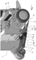
- the device 1 may be configured for applying articles such as labels or drinking straws on objects such as packages.
- the device 1 comprises an applicator member 2 which in the shown embodiment comprises two arms arranged in parallel. It is understood that the applicator member 2 may comprise only one arm or more than two arms.
- Each arm comprises a base element 3 and an arm element 4, wherein the arm element 4 is telescopically coupled to the base element 3 such that the arm element 4 is movable between a retracted state and an extended state.
- the arm element 4 is shown in its extended state.
- the device 1 further comprises a biasing member 5 which is configured to bias each arm element 4 towards the extended state.
- the biasing member 5 comprises a spring member.
- the application member 2 is pivotable coupled to an actuator.
- the actuator comprises an actuator shaft 6 which is arranged at a distance from a first rotation axis RA1 and is rotatable about the first rotation axis RA1.
- the actuator shaft 6 is eccentrically arranged about the first rotation axis RA1.
- the actuator shaft 6 is pivotable connected to the base element 3 of each arm. More specifically, an end portion 7 of each base element 3 is journaled on the actuator shaft 6 such that the arms are pivotable about the actuator shaft 6.
- the device 1 further comprises a support member 8 pivotable about a second rotation axis RA2 and arranged to slidingly support the applicator member 2.
- the second rotation axis RA2 is arranged in parallel with the first rotation axis RA1.
- the support member 8 comprises a support structure for each arm.
- the support member is journaled about a support shaft 9 extending along the second rotation axis RA2, and thus the support member 8 is rotatable about the second rotation axis RA2.
- Each support structure of the support member 8 is configured to slidingly support a mid-section 10 of each arm element 4 of the applicator member 2 and may comprise a sliding bearing configured to slidingly receive the mid-section 10.
- the applicator member 2 comprises an applicator head 11 which in response to rotation of the eccentrically arranged actuator shaft 6 about the first rotation axis RA1 is cyclically movable between a retrieval position in which the applicator head 11 is configured for retrieval of the article and an application position in which the applicator head 11 is configured for applying the article to the object.
- Each arm element 4 of the applicator member 2 is configured to assume its retracted state during movement of the applicator head 11 from the retrieval position to the application position and is configured to assume its extended state during movement of the applicator head 11 from the application position to the retrieval position.
- Each arm element 4 is further provided with a fixedly arranged projection 12 configured to engage the support member 8 during movement of the applicator head 11 from the retrieval position to the application position.
- the projection 12 of each arm element 4 is arranged on a side of the associated support structure facing the base element 3 telescopically coupled to the arm element 4.
- Each arm element 4 is configured to be brought to its retracted state in response to continued rotation of the eccentrically arranged actuator shaft 6 after the projection 12 has been brought into engagement with the associated support structure of the support member 8.
- the applicator head 11 is formed by the free end 13 of each arm element 4 and configured for retrieval and application of articles in the form of drinking straws. It is understood that the design of the applicator head is dependent upon the type of article to be retrieved and applied. For instance, the free ends of the arm elements may be interconnected in order to form an applicator head configured for application of articles in the form of labels or other type.
- the articles may be supplied from a source.
- Drinking straws may be provided as a web in which each drinking straw is wrapped in a protective envelope.
- a web may be supplied to a drive means 14 in the form of a feed wheel arranged retain the web.
- a knife 15 is arranged for separation of each enveloped drinking straw from the web. The separated enveloped drinking straws is then advanced one by one to a position associated with the retrieval position of the applicator head 11 of the applicator member 2.
- the device 1 comprises rotatable actuator wheel 16 eccentrically supporting the actuator shaft 6 at a distance from the first rotation axis RA1.
- the actuator wheel 16 may be rotated by a not shown motor, such as a servo motor.
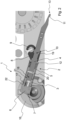
- the end portion 7 of the base element 3 is journaled in the actuator shaft 6 and thus pivotably relative the actuator shaft 6.
- the base element 3 defines a cavity 17 extending in the longitudinal direction of the arm.
- An end portion 18 of the arm element 4 is slidingly received by the cavity 17 such that the arm element 4 is telescopically coupled to the base element 3 and movable between the retracted state and the extended state.
- the support structure of the support member 8 is pivotable about the second rotation axis RA2 arranged in parallel with the first rotation axis RA1.
- the support structure comprises a sliding bearing 19 slidingly supporting the mid-section 10 of the arm element 4.
- a pin 20 extends transversely through the end portion 18 of the arm element 4.
- the opposing ends of the pin 20 is received by two oppositely arranged long holes 21 provided in the base element 3 and extending in the longitudinal direction of the arm.
- the retracted state and the extended state of the arm element 4 are defined by means of the pin 20 and the long holes 21.
- the projection 12 is arranged on the arm element 4 on the side of the support structure facing the base element 3.
- the projection 12 is the form of a washer.
- the arm of the applicator member 2 comprises a biasing member 5 in the form of a spring element configured for biasing the arm element 4 towards its extended state.
- the spring element is arranged between a heel 22 provided on the base portion 3 and the projection 12 in the form of a washer.
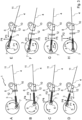
- the device 1 By rotation of the actuator shaft 6 in an anti-clock wise direction indicated by arrow P1, the device 1 will initially move from position A to positions B and C causing the base element 3 pivotable coupled to the actuator shaft 6 to be moved in a first lateral direction indicated by arrow P2 while the end portion 7 of the base element 3 is moved in a first transverse direction indicated by arrow P4.
- Movement of the base element 3 in the first lateral direction P2 will cause the projection 12 provided on the arm element 4 telescopically coupled to the base element 3 to be brought into engagement with the support member 8, preventing the arm element 4 to be pushed through the support member 8 slidingly supporting the mid-section 10 of arm element 4, i.e. the arm element 4 can no longer be moved together with the base element 3 in the first lateral direction P1. Instead, the end portion 18 of the arm element 4 will be pushed deeper into the cavity of the base element 3 - as shown in position B and C - against the action of the biasing member.
- the base element 3 pivotable coupled to the actuator shaft 6 will be moved in a second lateral direction indicated by arrow P3, which is opposite to the first lateral direction P2, while the end portion 7 of the base element 3 being continuously moved in the first transverse direction P4, whereby the arm element 4 is extended through the action of the biasing member while the projection 12 maintains its engagement with the support member 8.
- the applicator head 11 when the device 1 is operated through positions A-E, the applicator head 11 is moved from the retrieval position to the application position and simultaneous the arm element 4 is caused to being moved from the extended state to the retracted state (positions A-C) and back to the extended state (positions C-E). As a consequence, the applicator head 11 may be caused to be moved along a near linear path when being moved from the retrieval position to the application position.
- the base element 3 will initially (positions E-G) be moved in the second lateral direction P3 while the end portion 7 of the base element 3 is moved in a second transverse direction indicated by arrow P5, which is opposite to the first transverse direction P4, with the arm element 4 in its fully extended state.
- the projection 12 will be brought out of engagement with the support member 8, and thus the arm element 4 will maintain its fully extended state under the action of the biasing member.
- the base element 3 By continued rotation of the actuator shaft 6 (positions G-H and then back to position A) the base element 3 will be moved in the first lateral direction P2 while the end portion 7 is continuously moved in the second transverse direction P5. During this movement, the projection 12 will be moved towards the support member 8 but will not be brought into engagement with the same and, thus, the arm element 4 will maintain its fully extended state.
- the applicator head 11 will be moved along a curved path from the application position back to the retrieval position.
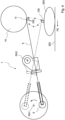
- Fig. 4 schematically illustrates the use of the device 1 for applying an article 100 on a moving object 200.
- the article 100 may be a drinking straw and the object 200 may be a package.
- the object is moved on a conveyor 300 in a feeding direction indicated by arrow P6.
- the figure illustrates the device 1 with its applicator head 11 in the retrieval position.
- the figure also indicates by dashed lines the device 1 with its applicator head 11 in the application position.
- the figure further illustrates a drive means 14 in the form of a feed wheel which has advanced the article 100 to a position associated with the retrieval position of the applicator head 11 such that the applicator head 11 may retrieve the article 100 from the drive means.
- the applicator head 11 By rotation of the actuator shaft 6 about the first rotation axis RA1 from position A to position E as illustrated in Fig. 3 , the applicator head 11 is moved from the retrieval position to the application position. Due to the retraction and subsequent extension of the applicator arm 4 during this movement, the applicator head 11 will be caused to follow a near linear path allowing a distinct application of the article 100 on the object 200.
- the article 100 may be applied to an application surface of the object 200 having been provided with an adhesive, such as hot melt, at an up stream situated station.
- an adhesive such as hot melt
- the applicator head 11 is moved from the application position back to the retrieval position, during which movement the arm element 4 is in its extended state and thus, the applicator head 11 will be caused to follow a curved path which initially has a component in the feeding direction P6 of the moving object 200.
Landscapes
- Engineering & Computer Science (AREA)
- Mechanical Engineering (AREA)
- Auxiliary Devices For And Details Of Packaging Control (AREA)
- Coating Apparatus (AREA)
- Spray Control Apparatus (AREA)
Claims (12)
- Vorrichtung zum Aufbringen eines Gegenstandes (100), wie etwa eines Trinkhalmes oder eines Etiketts, auf ein sich bewegendes Objekt (200), wobei die Vorrichtung umfasst:ein Aufbringungselement (2), das ein Basiselement (3) und ein Armelement (4) umfasst,ein Vorspannelement (5), undeine Stellwelle (6), die schwenkbar mit dem Basiselement verbunden ist, wobei die Stellwelle (6) exzentrisch angeordnet und um eine erste Drehachse (RA1) drehbar ist,wobei ein freies Ende (13) des Armelements (4) einen Aufbringungskopf (11) umfasst, der als Reaktion auf eine Drehung der exzentrisch angeordneten Stellwelle (6) um die erste Drehachse (RA1) zyklisch zwischen einer Entnahmeposition, in der der Aufbringungskopf (11) zur Entnahme des Gegenstands (100) eingerichtet ist, und einer Aufbringungsposition, in der der Aufbringungskopf (11) zum Aufbringen des Gegenstands (100) auf das Objekt (200) eingerichtet ist, bewegbar ist, dadurch gekennzeichnet, dass die Vorrichtung ferner umfasst:ein Trägerelement (8), das um eine zweite Drehachse (RA2) schwenkbar ist und einen mittleren Abschnitt (10) des Armelements (4) des Aufbringungselements (2) gleitend trägt,wobei das Armelement (4) derart teleskopisch mit dem Basiselement (3) gekoppelt ist, dass das Armelement (4) zwischen einem eingefahrenen Zustand und einem ausgefahrenen Zustand beweglich ist,wobei das Vorspannelement (5) eingerichtet ist, um das Armelement (4) in Richtung seines ausgefahrenen Zustands vorzuspannen,wobei das Armelement (4) eingerichtet ist, um während einer Bewegung des Aufbringungskopfes (11) von der Entnahmeposition in die Aufbringungsposition in seinen eingefahrenen Zustand gebracht zu werden, undwobei das Armelement (4) eingerichtet ist, seinen ausgefahrenen Zustand während einer Bewegung des Aufbringungskopfes (11) von der Aufbringungsposition in die Entnahmeposition anzunehmen.
- Vorrichtung nach Anspruch 1, wobei das Armelement (4) eingerichtet ist, um während einer Bewegung des Aufbringungskopfes (11) von der Entnahmeposition in die Aufbringungsposition derart aus dem ausgefahrenen Zustand in den eingefahrenen Zustand und dann zurück in den ausgefahrenen Zustand gebracht zu werden, dass der Aufbringungskopf (11) entlang einer nahezu linearen Bahn bewegt wird.
- Vorrichtung nach Anspruch 1 oder 2, wobei das Armelement (4) mit einem fest angeordneten Vorsprung (12) versehen ist, der eingerichtet ist, um mit dem Trägerelement (8) während einer Bewegung des Aufbringungskopfes (11) von der Entnahmeposition in die Aufbringungsposition in Eingriff zu kommen.
- Vorrichtung nach Anspruch 3, wobei das Armelement (4) eingerichtet ist, um als Reaktion auf eine fortgesetzte Drehung der exzentrisch angeordneten Stellwelle (6) in seinen eingefahrenen Zustand gebracht zu werden, wenn der Vorsprung (12) in Eingriff mit dem Trägerelement (8) gebracht wird.
- Vorrichtung nach Anspruch 3 oder 4, wobei der Vorsprung (12), der auf dem Armelement (4) vorgesehen ist, auf einer Seite des Trägerelements (8) angeordnet ist, die dem Basiselement (3) des Aufbringungselements (2) zugewandt ist.
- Vorrichtung nach einem der Ansprüche 3-5, wobei der Vorsprung (12) eingerichtet ist, um mit dem Vorspannelement (5) zusammenzuwirken.
- Vorrichtung nach einem der vorhergehenden Ansprüche, wobei das Armelement (4) eingerichtet ist, um während einer Bewegung des Aufbringungskopfes (11) von der Aufbringungsposition in die Entnahmeposition derart in dem ausgefahrenen Zustand gehalten zu werden, dass der Aufbringungskopf (11) entlang einer gekrümmten Bahn bewegt wird.
- Vorrichtung nach einem der vorhergehenden Ansprüche, wobei das Vorspannelement (5) ein Federelement umfasst.
- Vorrichtung nach einem der vorhergehenden Ansprüche, bei der das Aufbringungselement (2) ein zusätzliches Basiselement (3) und ein zusätzliches Armelement (4) umfasst, das teleskopisch damit gekoppelt ist, wobei sich das zusätzliche Basiselement (3) und das zusätzliche Armelement (4) parallel zu dem Basiselement (3) und dem Armelement (4) erstrecken.
- Vorrichtung nach einem der vorhergehenden Ansprüche, wobei der Aufbringungskopf (11) zur Entnahme und Aufbringung eines Gegenstandes (100) in Form eines Trinkhalmes angeordnet ist.
- Vorrichtung nach einem der vorhergehenden Ansprüche, wobei der Aufbringungskopf (11) zum Aufbringen des Gegenstands (100) auf ein Objekt (200) in Form einer Verpackung angeordnet ist.
- Vorrichtung nach einem der vorhergehenden Ansprüche, wobei das Trägerelement (8) ein Gleitlager (19) zum Tragen des mittleren Abschnitts (10) des Armelements (4) umfasst.
Priority Applications (10)
| Application Number | Priority Date | Filing Date | Title |
|---|---|---|---|
| PL21151387.4T PL4029796T3 (pl) | 2021-01-13 | 2021-01-13 | Urządzenie do dołączania artykułu do przemieszczającego się przedmiotu |
| ES21151387T ES3012082T3 (en) | 2021-01-13 | 2021-01-13 | Device for applying an article to a moving object |
| EP21151387.4A EP4029796B1 (de) | 2021-01-13 | 2021-01-13 | Vorrichtung zum aufbringen eines gegenstandes auf ein bewegtes objekt |
| PCT/EP2021/084022 WO2022152462A1 (en) | 2021-01-13 | 2021-12-02 | Device for applying an article to a moving object |
| AU2021420770A AU2021420770B2 (en) | 2021-01-13 | 2021-12-02 | Device for applying an article to a moving object |
| JP2023541644A JP7819197B2 (ja) | 2021-01-13 | 2021-12-02 | 移動物体に物品を貼り付けるためのデバイス |
| CA3204426A CA3204426A1 (en) | 2021-01-13 | 2021-12-02 | Device for applying an article to a moving object |
| CN202180089238.4A CN116829464B (zh) | 2021-01-13 | 2021-12-02 | 用于将物品敷贴到移动物体的设备 |
| US18/260,392 US12195223B2 (en) | 2021-01-13 | 2021-12-02 | Device for applying an article to a moving object |
| KR1020237026859A KR102843248B1 (ko) | 2021-01-13 | 2021-12-02 | 움직이는 객체에 아티클을 적용하는 장치 |
Applications Claiming Priority (1)
| Application Number | Priority Date | Filing Date | Title |
|---|---|---|---|
| EP21151387.4A EP4029796B1 (de) | 2021-01-13 | 2021-01-13 | Vorrichtung zum aufbringen eines gegenstandes auf ein bewegtes objekt |
Publications (3)
| Publication Number | Publication Date |
|---|---|
| EP4029796A1 EP4029796A1 (de) | 2022-07-20 |
| EP4029796C0 EP4029796C0 (de) | 2024-09-18 |
| EP4029796B1 true EP4029796B1 (de) | 2024-09-18 |
Family
ID=74181026
Family Applications (1)
| Application Number | Title | Priority Date | Filing Date |
|---|---|---|---|
| EP21151387.4A Active EP4029796B1 (de) | 2021-01-13 | 2021-01-13 | Vorrichtung zum aufbringen eines gegenstandes auf ein bewegtes objekt |
Country Status (10)
| Country | Link |
|---|---|
| US (1) | US12195223B2 (de) |
| EP (1) | EP4029796B1 (de) |
| JP (1) | JP7819197B2 (de) |
| KR (1) | KR102843248B1 (de) |
| CN (1) | CN116829464B (de) |
| AU (1) | AU2021420770B2 (de) |
| CA (1) | CA3204426A1 (de) |
| ES (1) | ES3012082T3 (de) |
| PL (1) | PL4029796T3 (de) |
| WO (1) | WO2022152462A1 (de) |
Family Cites Families (22)
| Publication number | Priority date | Publication date | Assignee | Title |
|---|---|---|---|---|
| US4047359A (en) * | 1976-09-01 | 1977-09-13 | Firma Heinrich Kuper | Device for packaging an object in foil |
| US4372797A (en) * | 1979-01-23 | 1983-02-08 | Tetra Pak International Ab | Method for the application of suction tubes to packing containers |
| DE3204011A1 (de) | 1982-02-05 | 1983-08-11 | Geyssel, Jürgen, 5000 Köln | Vorrichtung zum anbringen von gegenstaenden an packungen, flaschen oder anderen objekten |
| US4535584A (en) * | 1982-12-24 | 1985-08-20 | Tetra Pak International Akteibolag | Device for bonding an article to a commodity |
| JPS59187531A (ja) * | 1983-03-31 | 1984-10-24 | 株式会社 寺岡精工 | ラベル貼付機構 |
| SE454681B (sv) * | 1983-06-23 | 1988-05-24 | Tetra Pak Ab | Anordning for applicering av foremal pa forpackningsbehallare |
| JPS6169528A (ja) * | 1984-09-10 | 1986-04-10 | エービー テトラパック | 移送物品に対する体位変更装置 |
| DE3532839A1 (de) * | 1985-09-14 | 1987-03-26 | Overbeck Gmbh & Co | Verfahren zum anbringen von trinkhalmen an verpackungsbehaeltern, sowie vorrichtung zur durchfuehrung des verfahrens |
| JPS62143274A (ja) * | 1986-11-27 | 1987-06-26 | Sony Corp | テ−プカセツト |
| SE463865B (sv) * | 1987-09-04 | 1991-02-04 | Profor Ab | Anordning och saett att faesta och vika boejbara sugroer utmed sidan av en foerpackning |
| US5037366A (en) * | 1990-05-17 | 1991-08-06 | Gilliland Industrials Corporation | Device for attaching a straw to a carton container |
| DE4314631C1 (de) * | 1993-05-04 | 1994-04-28 | Uhlmann Pac Systeme Gmbh & Co | Vorrichtung zur Zuführung von Packbeilagen |
| SE509833C2 (sv) * | 1997-05-16 | 1999-03-15 | Tetra Laval Holdings & Finance | Anordning för applicering av sugrör |
| US6558490B2 (en) * | 1997-10-06 | 2003-05-06 | Smyth Companies, Inc. | Method for applying labels to products |
| US6526725B1 (en) * | 1999-06-23 | 2003-03-04 | Shrink Packaging Systems Corporation | Apparatus and method for attaching straws to containers |
| JP4589152B2 (ja) * | 2005-03-09 | 2010-12-01 | 株式会社コーセー | ラベル貼付装置 |
| SE531357C2 (sv) * | 2007-09-28 | 2009-03-10 | Ecolean Res & Dev As | Anordning och metod för hantering av en förpackning |
| CN201770042U (zh) * | 2010-06-04 | 2011-03-23 | 宿州市同科机械有限公司 | 一种包装容器的引导装置 |
| WO2016096380A1 (en) | 2014-12-15 | 2016-06-23 | Tetra Laval Holdings & Finance S.A. | A method of operating an apparatus for applying drinking straws to packaging containers and an apparatus operated by the method |
| EP3268285B1 (de) | 2015-03-11 | 2019-12-11 | Tetra Laval Holdings & Finance S.A. | Vorrichtung und verfahren zum anbringen von trinkhalmen an verpackungsbehältern |
| JP7165678B2 (ja) * | 2017-04-27 | 2022-11-04 | エスアイジー テクノロジー アーゲー | 付加的包装材料を貼着するための方法およびデバイス |
| WO2019060394A1 (en) * | 2017-09-19 | 2019-03-28 | Ball Corporation | METHOD AND APPARATUS FOR CONTAINER DECORATION |
-
2021
- 2021-01-13 EP EP21151387.4A patent/EP4029796B1/de active Active
- 2021-01-13 PL PL21151387.4T patent/PL4029796T3/pl unknown
- 2021-01-13 ES ES21151387T patent/ES3012082T3/es active Active
- 2021-12-02 US US18/260,392 patent/US12195223B2/en active Active
- 2021-12-02 AU AU2021420770A patent/AU2021420770B2/en active Active
- 2021-12-02 WO PCT/EP2021/084022 patent/WO2022152462A1/en not_active Ceased
- 2021-12-02 CA CA3204426A patent/CA3204426A1/en active Pending
- 2021-12-02 JP JP2023541644A patent/JP7819197B2/ja active Active
- 2021-12-02 KR KR1020237026859A patent/KR102843248B1/ko active Active
- 2021-12-02 CN CN202180089238.4A patent/CN116829464B/zh active Active
Also Published As
| Publication number | Publication date |
|---|---|
| JP2024502172A (ja) | 2024-01-17 |
| EP4029796A1 (de) | 2022-07-20 |
| JP7819197B2 (ja) | 2026-02-24 |
| US20240059447A1 (en) | 2024-02-22 |
| AU2021420770A1 (en) | 2023-07-13 |
| EP4029796C0 (de) | 2024-09-18 |
| WO2022152462A1 (en) | 2022-07-21 |
| KR20230131884A (ko) | 2023-09-14 |
| AU2021420770B2 (en) | 2025-06-05 |
| PL4029796T3 (pl) | 2025-02-24 |
| AU2021420770A9 (en) | 2024-09-26 |
| CN116829464B (zh) | 2025-11-25 |
| KR102843248B1 (ko) | 2025-08-06 |
| ES3012082T3 (en) | 2025-04-08 |
| CA3204426A1 (en) | 2022-07-21 |
| US12195223B2 (en) | 2025-01-14 |
| CN116829464A (zh) | 2023-09-29 |
Similar Documents
| Publication | Publication Date | Title |
|---|---|---|
| KR101805233B1 (ko) | 핸들-형성 기기 | |
| EP0944528B1 (de) | Etikettiervorrichtung mit etikettenrolle | |
| EP2804823A2 (de) | Artikeldosiervorrichtung, system und verfahren | |
| KR950012654B1 (ko) | 냅킨의 더미를 접는 기계에 의해 공급된 파일로부터 컨베이어에 이송하는 장치 및 방법 | |
| JPS59153752A (ja) | 材料ウエブを送る方法及びその装置 | |
| AU2007262577B2 (en) | Device for machining continuously successively transported, flat objects or an almost endless web of material | |
| EP4029796B1 (de) | Vorrichtung zum aufbringen eines gegenstandes auf ein bewegtes objekt | |
| EP0767736B1 (de) | Festhalteelement für kartons bei rotierenden zuführvorrichtung | |
| EP3446993A1 (de) | Etikettiermaschine mit einer verbesserten etikettentransfertrommel | |
| US7192502B2 (en) | Method and device for applying a label to a packet | |
| US4885895A (en) | Process and apparatus for feeding blanks to a folding unit | |
| US3709110A (en) | Apparatus and method for applying collars to container blanks | |
| US20090090230A1 (en) | Device for Cutting a Ribbon Made of Paper, Plastics or Similar Material | |
| EP2468640A1 (de) | Folienkennzeichnungssystem | |
| HK40094191A (zh) | 用於将物品敷贴到移动物体的设备 | |
| JP4922686B2 (ja) | 被搬送物のコンベア移載装置 | |
| WO2024114913A1 (en) | Pad device with double cam follower for transients | |
| KR20050116255A (ko) | 카카스 반제품의 각도 가변 절단 및 이송장치 | |
| GB2277074A (en) | Container labelling and/or dressing machine | |
| CN121335786A (zh) | 带有防撞元件的标签材料切割单元 | |
| EP2883805A1 (de) | Etikettiereinheit und Verfahren zum Anbringen eines Etiketts auf einen nichtzylindrischen, etikettenaufnehmenden Abschnitt eines Artikels | |
| EP1897812B1 (de) | Vorrichtung zum Spenden von auf einem Trägerband haftenden Etiketten | |
| US20190367200A1 (en) | Packaging sleeve feeding device | |
| JPH0675694U (ja) | 棒状体の長さ方向の位置決め装置 |
Legal Events
| Date | Code | Title | Description |
|---|---|---|---|
| PUAI | Public reference made under article 153(3) epc to a published international application that has entered the european phase |
Free format text: ORIGINAL CODE: 0009012 |
|
| STAA | Information on the status of an ep patent application or granted ep patent |
Free format text: STATUS: THE APPLICATION HAS BEEN PUBLISHED |
|
| AK | Designated contracting states |
Kind code of ref document: A1 Designated state(s): AL AT BE BG CH CY CZ DE DK EE ES FI FR GB GR HR HU IE IS IT LI LT LU LV MC MK MT NL NO PL PT RO RS SE SI SK SM TR |
|
| STAA | Information on the status of an ep patent application or granted ep patent |
Free format text: STATUS: REQUEST FOR EXAMINATION WAS MADE |
|
| 17P | Request for examination filed |
Effective date: 20221220 |
|
| RBV | Designated contracting states (corrected) |
Designated state(s): AL AT BE BG CH CY CZ DE DK EE ES FI FR GB GR HR HU IE IS IT LI LT LU LV MC MK MT NL NO PL PT RO RS SE SI SK SM TR |
|
| GRAP | Despatch of communication of intention to grant a patent |
Free format text: ORIGINAL CODE: EPIDOSNIGR1 |
|
| STAA | Information on the status of an ep patent application or granted ep patent |
Free format text: STATUS: GRANT OF PATENT IS INTENDED |
|
| INTG | Intention to grant announced |
Effective date: 20240419 |
|
| GRAS | Grant fee paid |
Free format text: ORIGINAL CODE: EPIDOSNIGR3 |
|
| GRAA | (expected) grant |
Free format text: ORIGINAL CODE: 0009210 |
|
| STAA | Information on the status of an ep patent application or granted ep patent |
Free format text: STATUS: THE PATENT HAS BEEN GRANTED |
|
| AK | Designated contracting states |
Kind code of ref document: B1 Designated state(s): AL AT BE BG CH CY CZ DE DK EE ES FI FR GB GR HR HU IE IS IT LI LT LU LV MC MK MT NL NO PL PT RO RS SE SI SK SM TR |
|
| REG | Reference to a national code |
Ref country code: GB Ref legal event code: FG4D |
|
| REG | Reference to a national code |
Ref country code: CH Ref legal event code: EP |
|
| REG | Reference to a national code |
Ref country code: IE Ref legal event code: FG4D |
|
| REG | Reference to a national code |
Ref country code: DE Ref legal event code: R096 Ref document number: 602021018815 Country of ref document: DE |
|
| U01 | Request for unitary effect filed |
Effective date: 20241010 |
|
| U07 | Unitary effect registered |
Designated state(s): AT BE BG DE DK EE FI FR IT LT LU LV MT NL PT RO SE SI Effective date: 20241030 |
|
| PG25 | Lapsed in a contracting state [announced via postgrant information from national office to epo] |
Ref country code: NO Free format text: LAPSE BECAUSE OF FAILURE TO SUBMIT A TRANSLATION OF THE DESCRIPTION OR TO PAY THE FEE WITHIN THE PRESCRIBED TIME-LIMIT Effective date: 20241218 |
|
| PG25 | Lapsed in a contracting state [announced via postgrant information from national office to epo] |
Ref country code: GR Free format text: LAPSE BECAUSE OF FAILURE TO SUBMIT A TRANSLATION OF THE DESCRIPTION OR TO PAY THE FEE WITHIN THE PRESCRIBED TIME-LIMIT Effective date: 20241219 |
|
| PGFP | Annual fee paid to national office [announced via postgrant information from national office to epo] |
Ref country code: GB Payment date: 20241217 Year of fee payment: 5 |
|
| U20 | Renewal fee for the european patent with unitary effect paid |
Year of fee payment: 5 Effective date: 20241217 |
|
| PG25 | Lapsed in a contracting state [announced via postgrant information from national office to epo] |
Ref country code: HR Free format text: LAPSE BECAUSE OF FAILURE TO SUBMIT A TRANSLATION OF THE DESCRIPTION OR TO PAY THE FEE WITHIN THE PRESCRIBED TIME-LIMIT Effective date: 20240918 |
|
| PG25 | Lapsed in a contracting state [announced via postgrant information from national office to epo] |
Ref country code: RS Free format text: LAPSE BECAUSE OF FAILURE TO SUBMIT A TRANSLATION OF THE DESCRIPTION OR TO PAY THE FEE WITHIN THE PRESCRIBED TIME-LIMIT Effective date: 20241218 |
|
| PG25 | Lapsed in a contracting state [announced via postgrant information from national office to epo] |
Ref country code: RS Free format text: LAPSE BECAUSE OF FAILURE TO SUBMIT A TRANSLATION OF THE DESCRIPTION OR TO PAY THE FEE WITHIN THE PRESCRIBED TIME-LIMIT Effective date: 20241218 Ref country code: NO Free format text: LAPSE BECAUSE OF FAILURE TO SUBMIT A TRANSLATION OF THE DESCRIPTION OR TO PAY THE FEE WITHIN THE PRESCRIBED TIME-LIMIT Effective date: 20241218 Ref country code: HR Free format text: LAPSE BECAUSE OF FAILURE TO SUBMIT A TRANSLATION OF THE DESCRIPTION OR TO PAY THE FEE WITHIN THE PRESCRIBED TIME-LIMIT Effective date: 20240918 Ref country code: GR Free format text: LAPSE BECAUSE OF FAILURE TO SUBMIT A TRANSLATION OF THE DESCRIPTION OR TO PAY THE FEE WITHIN THE PRESCRIBED TIME-LIMIT Effective date: 20241219 |
|
| REG | Reference to a national code |
Ref country code: ES Ref legal event code: FG2A Ref document number: 3012082 Country of ref document: ES Kind code of ref document: T3 Effective date: 20250408 |
|
| PG25 | Lapsed in a contracting state [announced via postgrant information from national office to epo] |
Ref country code: IS Free format text: LAPSE BECAUSE OF FAILURE TO SUBMIT A TRANSLATION OF THE DESCRIPTION OR TO PAY THE FEE WITHIN THE PRESCRIBED TIME-LIMIT Effective date: 20250118 |
|
| PG25 | Lapsed in a contracting state [announced via postgrant information from national office to epo] |
Ref country code: SM Free format text: LAPSE BECAUSE OF FAILURE TO SUBMIT A TRANSLATION OF THE DESCRIPTION OR TO PAY THE FEE WITHIN THE PRESCRIBED TIME-LIMIT Effective date: 20240918 |
|
| PGFP | Annual fee paid to national office [announced via postgrant information from national office to epo] |
Ref country code: ES Payment date: 20250317 Year of fee payment: 5 |
|
| PG25 | Lapsed in a contracting state [announced via postgrant information from national office to epo] |
Ref country code: CZ Free format text: LAPSE BECAUSE OF FAILURE TO SUBMIT A TRANSLATION OF THE DESCRIPTION OR TO PAY THE FEE WITHIN THE PRESCRIBED TIME-LIMIT Effective date: 20240918 |
|
| PG25 | Lapsed in a contracting state [announced via postgrant information from national office to epo] |
Ref country code: SK Free format text: LAPSE BECAUSE OF FAILURE TO SUBMIT A TRANSLATION OF THE DESCRIPTION OR TO PAY THE FEE WITHIN THE PRESCRIBED TIME-LIMIT Effective date: 20240918 |
|
| PLBE | No opposition filed within time limit |
Free format text: ORIGINAL CODE: 0009261 |
|
| STAA | Information on the status of an ep patent application or granted ep patent |
Free format text: STATUS: NO OPPOSITION FILED WITHIN TIME LIMIT |
|
| 26N | No opposition filed |
Effective date: 20250619 |
|
| REG | Reference to a national code |
Ref country code: CH Ref legal event code: PL |
|
| PG25 | Lapsed in a contracting state [announced via postgrant information from national office to epo] |
Ref country code: MC Free format text: LAPSE BECAUSE OF FAILURE TO SUBMIT A TRANSLATION OF THE DESCRIPTION OR TO PAY THE FEE WITHIN THE PRESCRIBED TIME-LIMIT Effective date: 20240918 |
|
| PG25 | Lapsed in a contracting state [announced via postgrant information from national office to epo] |
Ref country code: CH Free format text: LAPSE BECAUSE OF NON-PAYMENT OF DUE FEES Effective date: 20250131 |
|
| PG25 | Lapsed in a contracting state [announced via postgrant information from national office to epo] |
Ref country code: IE Free format text: LAPSE BECAUSE OF NON-PAYMENT OF DUE FEES Effective date: 20250113 |
|
| PGFP | Annual fee paid to national office [announced via postgrant information from national office to epo] |
Ref country code: PL Payment date: 20251229 Year of fee payment: 6 |
|
| U20 | Renewal fee for the european patent with unitary effect paid |
Year of fee payment: 6 Effective date: 20260115 |