EP4029487B1 - Elektrisches gehhilfefahrzeug - Google Patents
Elektrisches gehhilfefahrzeug Download PDFInfo
- Publication number
- EP4029487B1 EP4029487B1 EP21212449.9A EP21212449A EP4029487B1 EP 4029487 B1 EP4029487 B1 EP 4029487B1 EP 21212449 A EP21212449 A EP 21212449A EP 4029487 B1 EP4029487 B1 EP 4029487B1
- Authority
- EP
- European Patent Office
- Prior art keywords
- inclination
- electromagnetic brake
- control unit
- vehicle
- torque
- Prior art date
- Legal status (The legal status is an assumption and is not a legal conclusion. Google has not performed a legal analysis and makes no representation as to the accuracy of the status listed.)
- Active
Links
Images

Classifications
-
- A—HUMAN NECESSITIES
- A61—MEDICAL OR VETERINARY SCIENCE; HYGIENE
- A61H—PHYSICAL THERAPY APPARATUS, e.g. DEVICES FOR LOCATING OR STIMULATING REFLEX POINTS IN THE BODY; ARTIFICIAL RESPIRATION; MASSAGE; BATHING DEVICES FOR SPECIAL THERAPEUTIC OR HYGIENIC PURPOSES OR SPECIFIC PARTS OF THE BODY
- A61H3/00—Appliances for aiding patients or disabled persons to walk about
- A61H3/04—Wheeled walking aids for patients or disabled persons
-
- B—PERFORMING OPERATIONS; TRANSPORTING
- B60—VEHICLES IN GENERAL
- B60L—PROPULSION OF ELECTRICALLY-PROPELLED VEHICLES; SUPPLYING ELECTRIC POWER FOR AUXILIARY EQUIPMENT OF ELECTRICALLY-PROPELLED VEHICLES; ELECTRODYNAMIC BRAKE SYSTEMS FOR VEHICLES IN GENERAL; MAGNETIC SUSPENSION OR LEVITATION FOR VEHICLES; MONITORING OPERATING VARIABLES OF ELECTRICALLY-PROPELLED VEHICLES; ELECTRIC SAFETY DEVICES FOR ELECTRICALLY-PROPELLED VEHICLES
- B60L15/00—Methods, circuits, or devices for controlling the traction-motor speed of electrically-propelled vehicles
- B60L15/20—Methods, circuits, or devices for controlling the traction-motor speed of electrically-propelled vehicles for control of the vehicle or its driving motor to achieve a desired performance, e.g. speed, torque, programmed variation of speed
- B60L15/2009—Methods, circuits, or devices for controlling the traction-motor speed of electrically-propelled vehicles for control of the vehicle or its driving motor to achieve a desired performance, e.g. speed, torque, programmed variation of speed for braking
- B60L15/2018—Methods, circuits, or devices for controlling the traction-motor speed of electrically-propelled vehicles for control of the vehicle or its driving motor to achieve a desired performance, e.g. speed, torque, programmed variation of speed for braking for braking on a slope
-
- A—HUMAN NECESSITIES
- A61—MEDICAL OR VETERINARY SCIENCE; HYGIENE
- A61H—PHYSICAL THERAPY APPARATUS, e.g. DEVICES FOR LOCATING OR STIMULATING REFLEX POINTS IN THE BODY; ARTIFICIAL RESPIRATION; MASSAGE; BATHING DEVICES FOR SPECIAL THERAPEUTIC OR HYGIENIC PURPOSES OR SPECIFIC PARTS OF THE BODY
- A61H3/00—Appliances for aiding patients or disabled persons to walk about
- A61H3/04—Wheeled walking aids for patients or disabled persons
- A61H2003/043—Wheeled walking aids for patients or disabled persons with a drive mechanism
-
- A—HUMAN NECESSITIES
- A61—MEDICAL OR VETERINARY SCIENCE; HYGIENE
- A61H—PHYSICAL THERAPY APPARATUS, e.g. DEVICES FOR LOCATING OR STIMULATING REFLEX POINTS IN THE BODY; ARTIFICIAL RESPIRATION; MASSAGE; BATHING DEVICES FOR SPECIAL THERAPEUTIC OR HYGIENIC PURPOSES OR SPECIFIC PARTS OF THE BODY
- A61H3/00—Appliances for aiding patients or disabled persons to walk about
- A61H3/04—Wheeled walking aids for patients or disabled persons
- A61H2003/046—Wheeled walking aids for patients or disabled persons with braking means
-
- A—HUMAN NECESSITIES
- A61—MEDICAL OR VETERINARY SCIENCE; HYGIENE
- A61H—PHYSICAL THERAPY APPARATUS, e.g. DEVICES FOR LOCATING OR STIMULATING REFLEX POINTS IN THE BODY; ARTIFICIAL RESPIRATION; MASSAGE; BATHING DEVICES FOR SPECIAL THERAPEUTIC OR HYGIENIC PURPOSES OR SPECIFIC PARTS OF THE BODY
- A61H2201/00—Characteristics of apparatus not provided for in the preceding codes
- A61H2201/01—Constructive details
- A61H2201/0161—Size reducing arrangements when not in use, for stowing or transport
-
- A—HUMAN NECESSITIES
- A61—MEDICAL OR VETERINARY SCIENCE; HYGIENE
- A61H—PHYSICAL THERAPY APPARATUS, e.g. DEVICES FOR LOCATING OR STIMULATING REFLEX POINTS IN THE BODY; ARTIFICIAL RESPIRATION; MASSAGE; BATHING DEVICES FOR SPECIAL THERAPEUTIC OR HYGIENIC PURPOSES OR SPECIFIC PARTS OF THE BODY
- A61H2201/00—Characteristics of apparatus not provided for in the preceding codes
- A61H2201/12—Driving means
- A61H2201/1207—Driving means with electric or magnetic drive
-
- A—HUMAN NECESSITIES
- A61—MEDICAL OR VETERINARY SCIENCE; HYGIENE
- A61H—PHYSICAL THERAPY APPARATUS, e.g. DEVICES FOR LOCATING OR STIMULATING REFLEX POINTS IN THE BODY; ARTIFICIAL RESPIRATION; MASSAGE; BATHING DEVICES FOR SPECIAL THERAPEUTIC OR HYGIENIC PURPOSES OR SPECIFIC PARTS OF THE BODY
- A61H2201/00—Characteristics of apparatus not provided for in the preceding codes
- A61H2201/16—Physical interface with patient
- A61H2201/1602—Physical interface with patient kind of interface, e.g. head rest, knee support or lumbar support
- A61H2201/1628—Pelvis
- A61H2201/1633—Seat
-
- A—HUMAN NECESSITIES
- A61—MEDICAL OR VETERINARY SCIENCE; HYGIENE
- A61H—PHYSICAL THERAPY APPARATUS, e.g. DEVICES FOR LOCATING OR STIMULATING REFLEX POINTS IN THE BODY; ARTIFICIAL RESPIRATION; MASSAGE; BATHING DEVICES FOR SPECIAL THERAPEUTIC OR HYGIENIC PURPOSES OR SPECIFIC PARTS OF THE BODY
- A61H2201/00—Characteristics of apparatus not provided for in the preceding codes
- A61H2201/16—Physical interface with patient
- A61H2201/1602—Physical interface with patient kind of interface, e.g. head rest, knee support or lumbar support
- A61H2201/1635—Hand or arm, e.g. handle
-
- A—HUMAN NECESSITIES
- A61—MEDICAL OR VETERINARY SCIENCE; HYGIENE
- A61H—PHYSICAL THERAPY APPARATUS, e.g. DEVICES FOR LOCATING OR STIMULATING REFLEX POINTS IN THE BODY; ARTIFICIAL RESPIRATION; MASSAGE; BATHING DEVICES FOR SPECIAL THERAPEUTIC OR HYGIENIC PURPOSES OR SPECIFIC PARTS OF THE BODY
- A61H2201/00—Characteristics of apparatus not provided for in the preceding codes
- A61H2201/50—Control means thereof
- A61H2201/5023—Interfaces to the user
- A61H2201/5043—Displays
-
- A—HUMAN NECESSITIES
- A61—MEDICAL OR VETERINARY SCIENCE; HYGIENE
- A61H—PHYSICAL THERAPY APPARATUS, e.g. DEVICES FOR LOCATING OR STIMULATING REFLEX POINTS IN THE BODY; ARTIFICIAL RESPIRATION; MASSAGE; BATHING DEVICES FOR SPECIAL THERAPEUTIC OR HYGIENIC PURPOSES OR SPECIFIC PARTS OF THE BODY
- A61H2201/00—Characteristics of apparatus not provided for in the preceding codes
- A61H2201/50—Control means thereof
- A61H2201/5058—Sensors or detectors
- A61H2201/5061—Force sensors
-
- A—HUMAN NECESSITIES
- A61—MEDICAL OR VETERINARY SCIENCE; HYGIENE
- A61H—PHYSICAL THERAPY APPARATUS, e.g. DEVICES FOR LOCATING OR STIMULATING REFLEX POINTS IN THE BODY; ARTIFICIAL RESPIRATION; MASSAGE; BATHING DEVICES FOR SPECIAL THERAPEUTIC OR HYGIENIC PURPOSES OR SPECIFIC PARTS OF THE BODY
- A61H2201/00—Characteristics of apparatus not provided for in the preceding codes
- A61H2201/50—Control means thereof
- A61H2201/5058—Sensors or detectors
- A61H2201/5069—Angle sensors
-
- A—HUMAN NECESSITIES
- A61—MEDICAL OR VETERINARY SCIENCE; HYGIENE
- A61H—PHYSICAL THERAPY APPARATUS, e.g. DEVICES FOR LOCATING OR STIMULATING REFLEX POINTS IN THE BODY; ARTIFICIAL RESPIRATION; MASSAGE; BATHING DEVICES FOR SPECIAL THERAPEUTIC OR HYGIENIC PURPOSES OR SPECIFIC PARTS OF THE BODY
- A61H2201/00—Characteristics of apparatus not provided for in the preceding codes
- A61H2201/50—Control means thereof
- A61H2201/5058—Sensors or detectors
- A61H2201/5079—Velocity sensors
-
- A—HUMAN NECESSITIES
- A61—MEDICAL OR VETERINARY SCIENCE; HYGIENE
- A61H—PHYSICAL THERAPY APPARATUS, e.g. DEVICES FOR LOCATING OR STIMULATING REFLEX POINTS IN THE BODY; ARTIFICIAL RESPIRATION; MASSAGE; BATHING DEVICES FOR SPECIAL THERAPEUTIC OR HYGIENIC PURPOSES OR SPECIFIC PARTS OF THE BODY
- A61H2203/00—Additional characteristics concerning the patient
- A61H2203/04—Position of the patient
- A61H2203/0406—Standing on the feet
-
- A—HUMAN NECESSITIES
- A61—MEDICAL OR VETERINARY SCIENCE; HYGIENE
- A61H—PHYSICAL THERAPY APPARATUS, e.g. DEVICES FOR LOCATING OR STIMULATING REFLEX POINTS IN THE BODY; ARTIFICIAL RESPIRATION; MASSAGE; BATHING DEVICES FOR SPECIAL THERAPEUTIC OR HYGIENIC PURPOSES OR SPECIFIC PARTS OF THE BODY
- A61H2203/00—Additional characteristics concerning the patient
- A61H2203/04—Position of the patient
- A61H2203/0425—Sitting on the buttocks
- A61H2203/0431—Sitting on the buttocks in 90°/90°-position, like on a chair
Definitions
- the present invention relates to an electric walking assisting vehicle.
- Patent Literature 1 discloses an electric vehicle which includes an electromagnetic brake for locking a motor shaft and is operable to release locking of the electromagnetic brake by operating a hand-push switch in order to enable hand-push traveling upon storing the electric vehicle into a narrow garage or the like.
- Patent Literature 1 JP 4505694 B2
- EP 3 308 761 A1 discloses an electric vehicle capable of determining, without using a grip sensor or the like, whether a user is operating the electric vehicle, and a method of braking the same.
- the electric vehicle includes an inclination sensor, a wheel or an endless track provided on a frame, a brake unit for braking the wheel or the endless track, and a control unit for controlling the brake unit. Based on a change in acceleration of the electric vehicle, the control unit determines whether a user is operating the electric vehicle.
- An object of the present invention is to prevent idle traveling upon hand-push traveling in a state in which motors of an electric walking assisting vehicle are stopped.
- the electric walking assisting vehicle according to the present invention is configured such that only when the inclination is less than the predetermined threshold value, the forcible releasing means for the electromagnetic brake is enabled and when the inclination is the predetermined threshold value or more, the forcible releasing means is disabled, when the inclination is the predetermined threshold value or more, the electromagnetic brake is maintained in a locked state, and idle traveling on a slope due to self-weight can be reliably prevented.
- the inclination is less than the predetermined threshold value, locking of the electromagnetic brake is released, and moving thereof by hand-pushing can be made without braking resistance.
- an electric vehicle 1 includes a vehicle body 2, which is constituted of a moving base 21 (lower traveling body) and an upper frame 22 which is installed in a standing manner in the rear of the moving base 21 (a rear side base 24), and can be utilized in a walking assisting vehicle mode (1) indicated by a solid line in Figure 1 and a compact electric vehicle mode (riding mode 1') indicated by a two-dot chain line in Figure 1 .
- the moving base 21 includes the rear side base 24 (main body part) which is provided with left and right driving wheels 4 (rear wheels) and the upper frame 22 and a front side base 25 which is provided with left and right driven wheels 5 (front wheels), the front side base 25 is coupled to a front side of the rear side base 24 in a manner slidable in a front-rear direction, and a wheel base of the moving base 21 is configured in such a way as to be extendable and contractible.
- the left and right driving wheels 4 are independently driven by left and right motor units 40 (40L and 40R) which are mounted on the rear side base 24.
- the left and right driven wheels 5 are constituted of universal wheels (omni-wheels or omnidirectional wheels), each of which includes, in a treading portion thereof, multiple rollers 50 which can rotate around an axis in a circumferential direction.
- the electric vehicle 1, as described later, can be steered, driven, and braked only by controlling the left and right motor units 40L and 40R.
- the upper frame 22 is of an inverse U-shape or a gate shape in which upper ends of a pair of left and right side part frames installed in a standing manner upward from both left and right side parts of the rear side base 24 are joined by an upper end frame extending in a vehicle width direction, a lower end portion of a stem 31 of a rear handle 3 is rigidly coupled to a joining part 23 in a central portion of the upper end frame in the vehicle width direction, and a seat back 6 is supported on the joining part 23.
- the rear handle 3 is of a T-bar shape and has a pair of left and right gripping parts which extend from a connecting part 32 with the upper end of the stem 31.
- the left and right gripping parts of the rear handle 3 are provided with a gripping sensor 30 which detects a state in which a user (or a helper) grips the gripping parts (hands-on).
- a gripping sensor 30 As the gripping sensor 30, a touch sensor such as a capacitance sensor and a pressure sensor can be used.
- the left and right gripping parts of the rear handle 3 serve as an operation part.
- a base part of a support frame 81 of an armrest 8 is fixed.
- a front end part of the armrest 8 on a right side, which is a depth side in Figure 1 is provided with a riding mode operation unit 83, and a front end part of the armrest 8 on a left side, which is a front side in Figure 1 , is provided with a display part 80 on an upper surface of the gripping parts (83) having the same shapes.
- the riding mode operation unit 83 is configured by a biaxial joystick, which is tiltable in a front-rear direction and a left-right direction, or the like.
- a support frame 71 of the seat 7 is pivotably supported to a pivotal supporting part 27, which protrudes forward from the bending portion of the upper frame 22 (side part frame), by a shaft 7a in the vehicle width direction, a lower end of the support frame 71 is coupled to the front side base 25 (pin) via a coupling part 7b (slot) in a pivotable and slidable manner.
- the front side base 25 slides backward, the moving base 21 is shortened, and the walking assisting vehicle mode (1) in which the user can grip and operate the rear handle 3 while standing and walking is set.
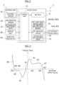
- FIG. 2 is a block diagram showing a control system of the electric vehicle 1.
- the electric vehicle 1 includes a battery 9 which supplies electric power to the left and right motor units 40 (40L and 40R) and a control unit 10 for controlling the left and right motor units 40 (40L and 40R), and the control unit 10 includes an interlock mechanism which implements control corresponding to the walking assisting vehicle mode (1) and control corresponding to the riding mode (1').
- the riding mode operation unit 83 is disabled, and based on detection information detected by an inclination sensor 20, left and right speed sensors 43, and the like and a previously set control map, the control unit 10 executes control of the left and right motor units 40 (40L and 40R).
- the gripping sensor 30 detects only gripping (hands-on/hands-off) of the rear handle 3 by the user and is not involved in torque control of the motor units 40.
- the gripping sensor 30 is disabled, and based on an operation of the riding mode operation unit 83 and detection information detected by the inclination sensor 20, the control unit 10 executes control of the left and right motor units 40 (40L and 40R).
- the control unit 10 is constituted of: a computer (microcomputer) which includes ROM having stored therein programs and data for executing the control in the abovementioned modes, RAM which temporarily stores an arithmetic processing result, a CPU which performs arithmetic processing, and the like; a driving circuit (motor driver) for left and right motors 41; a power supply circuit including a relay which turns on/off the electric power of the battery 9; and the like.
- Each of the left and right motor units 40 includes a motor 41, an electromagnetic brake 42 for locking a rotor of the motor 41, and a rotation position sensor (43) for detecting a rotation position of the motor 41, and a driving shaft of the motor 41 is connected to each of driving wheels 4 (4L and 4R) via a deceleration gear, not shown, so as to be operable to transmit power thereto.
- each of the left and right motors 41 is constituted of a brushless DC motor which switches a current of each phase coil by a driving circuit so as to match each phase of the rotor, which is detected by the rotation position sensor (43), and as described later, in the walking assisting vehicle mode (1), a rotation position sensor (Hall sensor) is used as a rotation speed sensor 43.
- a rotation position sensor Hall sensor
- each of the left and right motors 41 includes a current sensor for detecting a coil current.
- This coil current corresponds to torque of each of the left and right motors 41, and the control unit 10 controls the coil current, thereby executing torque control of the left and right motors 41.
- a negative actuated type electromagnetic brake which locks the driving shafts of the motors 41 in a non-excited state and unlocks the driving shafts thereof in an excited state.
- the electric vehicle 1 can be reliably stopped upon key-off or during stopping without consuming electric power.
- an electromagnetic brake release switch 34 is provided.
- the electromagnetic brake release switch 34 is provided, preferably, in such a way as to neighbor the gripping parts of the rear handle 3, irrespective of gripping detection by the gripping sensor 30, the electromagnetic brake release switch 34 can be operated.
- a momentarily-operable release switch for example, a push button switch which releases locking of the electromagnetic brake 42 with a contact closed in a state in which the user operates the electromagnetic brake release switch 34 and locks the electromagnetic brake 42 with the contact opened when the user detaches his or her hand from the electromagnetic brake release switch 34 is suitable.
- the control unit 10 In a case in which during stopping of the motors 41, an inclination of the vehicle body 2 detected by the inclination sensor 20 is less than a predetermined threshold value (for example, ⁇ four degrees), the control unit 10 enables operation of the electromagnetic brake release switch 34, and in a case in which the inclination of the vehicle body 2 is the predetermined threshold value or more, the control unit 10 disables the operation of the electromagnetic brake release switch 34.
- a predetermined threshold value for example, ⁇ four degrees
- the control unit 10 After the electromagnetic brake 42 has been released by the operation of the electromagnetic brake release switch 34, even when the inclination of the vehicle body 2 detected by the inclination sensor 20 is the predetermined threshold value (for example, ⁇ four degrees) or more, the control unit 10 does not immediately disable the operation of the electromagnetic brake release switch 34 until a predetermined period of time (for example, five seconds) has elapsed.
- a predetermined period of time for example, five seconds
- This postponement time may be configured in such a way as to allow the user to set the postponement time (in consideration of an assumed usage form).
- the control unit 10 disables the operation of the electromagnetic brake release switch 34 and locks the electromagnetic brake 42.
- the front wheels are universal wheels 5, it is preferable that determination be made based on an inclination (corresponding to a road surface inclination) which is obtained from a front-rear direction inclination ⁇ p and a lateral inclination ⁇ r of the vehicle body 2, because an inclination threshold value is relatively small, in a case in which any of the front-rear direction inclination ⁇ p or the lateral inclination ⁇ r is the predetermined threshold value or more, the determination of the inclination threshold value or more may be made.
- a threshold value of the front-rear direction inclination ⁇ p and a threshold value of the lateral inclination ⁇ r can also be separately set.
- the control unit 10 disables the operation of the electromagnetic brake release switch 34 during driving of the motors 41, and during stopping of the motors 41 and in a case in which a rotation speed detected by the rotation speed sensors 43 is less than a predetermined threshold value, that is, only in a case in which the vehicle speed is less than a predetermined threshold value (for example, ⁇ 0.1 km/h) which can be practically presumed to be zero, the control unit 10 enables the operation of the electromagnetic brake release switch 34.
- a predetermined threshold value for example, ⁇ 0.1 km/h
- the control unit 10 In a case in which after the electromagnetic brake 42 has been released by the operation of the electromagnetic brake release switch 34, the rotation speed detected by the rotation speed sensors 43 has reached an upper limit value, that is, in a case in which the vehicle speed has reached a predetermined upper limit value (for example, four km/h), the control unit 10 disables the operation of the electromagnetic brake release switch 34 and locks the electromagnetic brake 42.
- a speed of the electric vehicle 1 is controlled to be less than an upper limit (for example, six km/h) in a standard walking speed range of an assumed user by the below-described control.
- an upper limit speed upon forcibly releasing the electromagnetic brake to be a value (for example, four km/h) smaller than the abovementioned upper limit, the speed thereof can be reliably made to fall within the upper limit speed range at the time when the electric vehicle 1 is moving by hand-pushing.
- the forcible release of the electromagnetic brake 42 by the electromagnetic brake release switch 34 presupposes use for a purpose of temporarily moving the electric vehicle 1 in a case of urgency, at the time of an emergency, or the like.
- the inclination sensor 20 is mounted on a circuit board of the control unit 10 which is mounted inside the moving base 21 (rear side base 24) of the vehicle body 2, and a biaxial inclination sensor for detecting inclination of the vehicle body 2 in a front-rear direction and a lateral direction, an acceleration sensor, or a multiaxial inertial sensor in which an acceleration sensor and an angular acceleration sensor (gyroscope sensor) are integrated can be used.
- the electric vehicle 1 configured as described above is, in the walking assisting vehicle mode (1), operable to perform torque assist in all operations of forward moving/backward moving/turning by generating torque in the left and right motor units 40 (40L and 40R) in accordance with rotation speeds of the left and right driving wheels 4L and 4R, which are detected by the left and right rotation speed sensors 43, in conjunction with operations of pushing/pulling the vehicle body 2 in a state in which the user grips the rear handle 3.
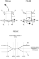
- Figure 3 shows a basic torque map which defines relationship between a rotation speed V detected by each of the left and right rotation speed sensors 43 and a torque T command value of each of the left and right motors 41.
- the rotation position sensors of the left and right motors 41 are used, and a rotation speed of each of the left and right driving wheels 4L and 4R is detected as the rotation speed V of each of the left and right motors 41 (rotors), which is increased by a gear ratio of the deceleration gear.
- each of the left and right motors 41 is a three-phase brushless DC motor
- up to 1/6 rotation of 60 degrees can be detected by three rotation position sensors (43) which are arranged at intervals of 120 degrees, and since when the gear ratio of the deceleration gear is 10:1 and each of the left and right driving wheels 4L and 4R rotates at 36 degrees, each of the left and right motors 41(rotors) makes one rotation, as the rotation speed of each of the left and right motors 41 (rotors) or a number of revolutions [rpm] per unit time, practically sufficient resolution can be obtained.
- a basic operation in the walking assisting vehicle mode (1) is an operation of moving forward in a state in which the user grips the rear handle 3.
- an operation origin Vn neutral point
- Vn neutral point
- the basic torque map shown in Figure 3 has a peak region A1 (-Vn to +Va1) of a torque command value on a positive side of the operation origin Vn, which generates starting torque in the forward moving direction, and a peak region B1 (-Vn to -Vb1) of a torque command value on a negative side of the operation origin Vn, which generates starting torque in the backward moving direction.
- the basic torque map shown in Figure 3 has a steady torque region A2 (+Va1 to +Va2) in the forward moving direction, which is on a further positive side in the peak region A1 on the forward moving side and has a steady torque region B2 (-Vb1 to -Vb2) in the backward moving direction, which is on a further negative side in the peak region B 1 on the backward moving side.
- a torque command value itself be less than that in the steady torque region A2 in the forward moving direction and an increasing rate of the torque command value in accordance with the rotation speed also be small, and the torque command value in the steady torque region B2 in an example shown in Figure 3 is constant.
- the basic torque map shown in Figure 3 has a braking torque region A3 (+V2 to +V3) in the forward moving direction, which is on a further positive side in the steady torque region A2 on the forward moving side, and has a braking torque region B3 (-Vb2 to -Vb3) in the backward moving direction, which is on a further negative side in the steady torque region B2 on the backward moving side.
- a torque command value is decreased as a traveling speed of the electric vehicle 1 approaches an upper limit in a standard walking speed range of the assumed user (for example, 6 km/h), braking torque is further generated for the electric vehicle 1 by executing torque assist in a direction inverse to a traveling direction in the neighborhood of the upper limit in the assumed walking speed range, and a traveling speed of the electric vehicle 1 is controlled to fall within the assumed walking speed range.
- a standard walking speed range of the assumed user for example, 6 km/h
- the similar is applied also to the braking torque region B3 in the backward moving direction, because a walking speed during the backward moving is slow, as compared with a walking speed during the forward moving, braking torque of a lower rotation speed lower than a rotation speed on the forward moving side is generated.
- the basic torque map is stored as a look-up table in an ROM area of the control unit 10.
- the torque command values in accordance with the peak region A1 (starting torque region), the steady torque region A2, and the braking torque region A3 in the forward moving direction are given by the basic torque map shown in Figure 3 , the operation of gripping and pushing the rear handle 3 by the user is thereby further promptly started and shifting to the steady torque region A2 is performed, and thereafter, by exceeding the steady torque region A2 and increasing the speed, the torque assist in a braking direction is executed in the braking torque region A3, and when deceleration to a value not greater than values in the steady torque region A2 is performed, the torque assist in a speed increasing direction is executed in the peak region A1.
- the steady torque region A2 corresponding to the standard walking speed range (+Va1 to +Va2) is maintained only by the simple operation of gripping and pushing/pulling the rear handle 3 by the user without special awareness of the user, thus leading to advantages in that stable assist can be performed.
- torque assist increase and decrease of the rotation speed V by the operations of gripping and pushing/pulling the rear handle 3 by the user and increase and decrease of the rotation speed V by driving of the left and right motors 41 (torque assist) are not distinguished (it is not necessary to distinguish therebetween), and the torque assist is executed in accordance with the rotation speed V as a result of cooperative operations of the operation of gripping and pushing the rear handle 3 by the user and the operation by the driving force of the left and right motors 41.
- each of the motor units 40 (40L and 40R) of the left and right driving wheels 4L and 4R includes the rotation speed sensor 43, and in a case in which the operation of pushing/pulling the vehicle body 2 is performed with left and right forces which are different from each other in a state in which the user grips the rear handle 3 by left and right hands (or either one of the hands), a difference between rotation speeds of the left and right driving wheels 4L and 4R is caused.
- a rotation speed VR which is greater than a rotation speed VL of the driving wheel 4L on a left side
- the basic torque map shown in Figure 3 is applied to control of the motor units 40 (40L and 40R) of the left and right driving wheels 4L and 4R as it is, even if a slight rotation speed difference is caused, the rotation speed difference is increased by left and right individual torque assists, the electric vehicle 1 turns, and stable forward moving/backward moving cannot thereby be performed.
- a torque assist in accordance with the rotation speed difference ⁇ V is executed as described below by a torque map which defines relationship between the rotation speed difference ⁇ V of the left and right driving wheels 4L and 4R and additional torque TL and TR, thereby allowing stable forward moving/backward moving assist and turning assist to be appropriately executed in accordance with circumstances.
- this additional torque map is also stored as a look-up table in the ROM area of the control unit 10.
- a torque map shown in Figure 7C is used in combination, and compensation torque Tca, Tcb, and Td which offset the loads caused in accordance with the inclination (angle) ⁇ p which is detected by the inclination sensor 20 are added to a torque command value.
- a compensation torque command value of the additional torque map is superimposed on a torque command value of the basic torque map.
- this additional torque map is also stored as a look-up table in the ROM area of the control unit 10.
- a threshold value (less than ⁇ p1 and a dead zone) is set for the inclination ⁇ p, and in a case in which the inclination ⁇ p is less than the threshold value and no influence is exerted on the basic control and the turning control, the torque compensation is not performed.
- Figure 8 shows a lateral inclination compensation assist in a case in which the electric vehicle 1 in the walking assisting vehicle mode (1) moves forward on a road surface 93 which has an inclination (lateral inclination ⁇ r) in a direction intersecting with a traveling direction of the electric vehicle 1 (or a case in which the electric vehicle 1 moves forward in a direction intersecting with the inclination ⁇ r of the slope 93).
- a threshold value (dead zone) is set also for the lateral inclination ⁇ r and in a case in which the lateral inclination ⁇ r is less than the threshold value and no influence is exerted on the basic control and the turning control, the lateral inclination compensation assist is not performed.
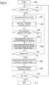
- the electric vehicle 1 configured as described above When the electric vehicle 1 configured as described above is turned on by operating a key 11 and the system is activated, in accordance with a frame form when activated, the walking assisting vehicle mode (1) or the riding mode (1') is set. Note that as already described, in a state in which the electric vehicle 1 is stopping, the electromagnetic brake 42 is in a locked state.
- the gripping sensor 30 is in an operation state.
- the inclination sensor 20 detects the inclination ⁇ p in the forward-backward direction of the vehicle body 2 and the inclination ⁇ r in a lateral direction (step 102).
- step 104 it is checked whether or not the left and right electromagnetic brakes 42 are in a locked state (step 104), and when the left and right electromagnetic brakes 42 are in the locked state (at initial activation time or the like), lock of the left and right electromagnetic brakes 42 is released (step 105).
- the electric vehicle 1 is at rest, an external force resulting from the inclination is offset by compensation torque, and regardless of absence or presence of the inclination, the electric vehicle 1 is in an immediately movable state.
- the user performs the operation of pushing/pulling the rear handle 3, whereby the left and right driving wheels 4L and 4R are rotated, and when rotation speeds V (VL and VR) are detected by the rotation speed sensor 43, in accordance with the rotation speeds V (VL and VR) and the basic torque map, torque is generated in the left and right motor units 40 (40L and 40R), and the torque assist such as the forward moving/backward moving/turning is executed (step 106).
- step 107 detection of the gripping state (hands-on) by the gripping sensor 30 is continued (step 107), and when the gripping state comes not to be detected by the gripping sensor 30 and the control unit 10 determines hands-off, torque command values for the left and right motor units 40 (40L and 40R) are gradually decreased, and torque assist in which the electric vehicle 1 is decelerated and stopped is executed (step 108).
- predetermined time for example, two seconds
- step 110 In a state in which the left and right electromagnetic brakes 42 are locked, when an operation of turning off the key 11 is detected (step 110), electric power supply to the left and right motor units 40 (40L and 40R) is stopped and thereafter, the system is shut down (step 111).
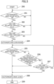
- a walking assisting vehicle mode (1) or a riding mode (1') in a case in which in a state in which the motors 41 are stopped, the electromagnetic brake release switch 34 is turned on (step 201), it is detected whether or not the inclination of the vehicle body 2 detected by the inclination sensor 20 is less than the predetermined threshold value (for example, ⁇ four degrees) (step 202), and furthermore, it is detected whether or not the vehicle speed detected by the rotation speed sensors 43 is less than the predetermined threshold value (for example, ⁇ 0.1 km/h) (step 203).
- the predetermined threshold value for example, ⁇ four degrees
- the operation of the electromagnetic brake release switch 34 is disabled and the electromagnetic brake 42 is maintained in a locked state.
- step 205 when for example, the user's hand is detached from the electromagnetic brake release switch 34, the electromagnetic brake 42 is immediately locked (step 208).
- the electromagnetic brake release switch 34 is turned on, in a case in which detection of the inclination of the vehicle body 2 by the inclination sensor 20 and detection of the vehicle speed by the rotation speed sensors 43 are continued and a state in which the inclination detected by the inclination sensor 20 is the predetermined threshold value or more is continuously detected for the predetermined period of time (for example, five seconds) or more (step 206), or in a case in which the vehicle speed detected by the rotation speed sensors 43 has reached the predetermined threshold value (step 207), the electromagnetic brake 42 is immediately locked (step 208).
- the electromagnetic brake 42 is maintained in a released state. Therefore, while the electric vehicle 1 is moving by hand-pushing, it is made possible to climb over the step difference or to descend the step difference by lifting up the front wheels or the rear wheels.
- the present invention can be implemented as an electric walking assisting vehicle including no riding mode.
Landscapes
- Health & Medical Sciences (AREA)
- Rehabilitation Therapy (AREA)
- Animal Behavior & Ethology (AREA)
- Veterinary Medicine (AREA)
- Public Health (AREA)
- Epidemiology (AREA)
- Pain & Pain Management (AREA)
- Physical Education & Sports Medicine (AREA)
- Life Sciences & Earth Sciences (AREA)
- General Health & Medical Sciences (AREA)
- Engineering & Computer Science (AREA)
- Transportation (AREA)
- Power Engineering (AREA)
- Mechanical Engineering (AREA)
- Electric Propulsion And Braking For Vehicles (AREA)
- Rehabilitation Tools (AREA)
- Automatic Cycles, And Cycles In General (AREA)
- Handcart (AREA)
Claims (6)
- Elektrisches Gehhilfefahrzeug (1), Folgendes umfassend:einen Fahrzeugaufbau (2) mit einer Vorwärts-Rückwärts-Richtung und einer Breitenrichtung;ein linkes und ein rechtes Antriebsrad (4L, 4R), die in der Breitenrichtung des Fahrzeugaufbaus (2) beabstandet sind;linke und rechte Motoren (40L, 40R), die jeweils zur Leistungsübertragung auf das linke und rechte Antriebsrad (4L, 4R) verbunden sind;ein Griffteil (3) zum Erkennen, dass das Griffteil von einem Benutzer in einer Stehend- und Gehhaltung gegriffen wird;eine elektromagnetische Bremse (42) zum Blockieren der linken und rechten Antriebsräder (4L, 4R) oder der linken und rechten Motoren (40L, 40R);Mittel für die erzwungene Freigabe der elektromagnetischen Bremse (42), wobei Mittel für die erzwungene Freigabe einen vom Benutzer betätigbaren Freigabeschalter umfassen;einen Neigungssensor (20) zum Erfassen einer Neigung des Fahrzeugaufbaus;und eine Steuereinheit (10) zum Steuern der linken und rechten Motoren, wobei die Steuereinheit (10) derart konfiguriert ist, dass während des Anhaltens der linken und rechten Motoren (40L, 40R), wenn die durch den Neigungssensor (20) erfasste Neigung kleiner als ein vorbestimmter Schwellenwert ist, die Steuereinheit (10) das Hilfsmittel für die erzwungene Freigabe der elektromagnetischen Bremse (42) aktiviert und wenn die Neigung den vorbestimmten Schwellenwert oder mehr beträgt, die Steuereinheit (10) das Hilfsmittel für die erzwungene Freigabe deaktiviert.
- Elektrisches Gehhilfefahrzeug (1) nach Anspruch 1, wobei die Steuereinheit (10) derart konfiguriert ist, dass während der erzwungenen Freigabe der elektromagnetischen Bremse (42) durch das Hilfsmittel für die erzwungenen Freigabe, wenn die durch den Neigungssensor (20) erfasste Neigung den vorbestimmten Schwellenwert oder mehr kontinuierlich für eine vorbestimmte Zeitspanne beträgt, die Steuereinheit (10) die elektromagnetische Bremse (42) in einen verriegelten Zustand versetzt.
- Elektrisches Gehhilfefahrzeug (1) nach Anspruch 1 oder 2, ferner umfassend Drehzahlsensoren (43), die individuell Drehgeschwindigkeiten des linken und rechten Antriebsrades (4L, 4R) erfassen, wobei die Steuereinheit (10) derart konfiguriert ist, dass, wenn jede der durch die Drehzahlsensoren (43) erfassten Drehgeschwindigkeiten des linken und rechten Antriebsrades (4L, 4R) kleiner als ein vorbestimmter Schwellenwert ist, die Steuereinheit (10) das Hilfsmittel für die erzwungene Freigabe (43) der elektromagnetischen Bremse (42) aktiviert und wenn während der erzwungenen Freigabe der elektromagnetischen Bremse (42) durch das Hilfsmittel für die erzwungene Freigabe jede der Drehzahlen einen oberen Grenzwert erreicht hat, die Steuereinheit (10) das Hilfsmittel für die erzwungene Freigabe (43) deaktiviert und die elektromagnetische Bremse (42) in einen verriegelten Zustand versetzt.
- Elektrisches Gehhilfefahrzeug (1) nach einem der Ansprüche 1 bis 3, ferner umfassend einen Griffsensor (30) zum Erfassen, dass das Griffteil (3) von dem Benutzer gegriffen wird, wobei die Steuereinheit (10) derart konfiguriert ist, dass in einem Zustand, in dem der Griffsensor (30) das Greifen erfasst, in Abhängigkeit der von den Drehgeschwindigkeitssensoren (43) erfassten Drehzahlen der linken und rechten Antriebsräder (4L, 4R) und einer Drehmomentabbildung, die Steuereinheit ein Drehmoment für den linken und rechten Motor generiert.
- Elektrisches Gehhilfefahrzeug (1) nach einem der Ansprüche 1 bis 4, wobei der Fahrzeugaufbau einen klappbaren Sitz (7) und eine Bedieneinheit (83) umfasst, die von dem auf dem Sitz (7) sitzenden Benutzer betätigbar ist, und das elektrische Gehhilfefahrzeug als ein kompaktes Elektrofahrzeug verwendbar ist, und auch in einer Form des kompakten Elektrofahrzeugs, wobei die Steuereinheit (10) derart konfiguriert ist, dass während des Anhaltens des linken und rechten Motors (40L, 40R), wenn die durch den Neigungssensor (20) erfasste Neigung kleiner als der vorbestimmte Schwellenwert ist, die Steuereinheit (10) das Hilfsmittel für die erzwungene Freigabe der elektromagnetischen Bremse (42) aktiviert und wenn die Neigung den vorbestimmten Schwellenwert oder mehr beträgt, die Steuereinheit (10) das Hilfsmittel für die erzwungene Freigabe deaktiviert.
- Elektrisches Gehhilfefahrzeug (1) nach einem der Ansprüche 1 bis 5, wobei die elektromagnetische Bremse (42) eine negativ betätigte elektromagnetische Bremse ist, die in einem nicht angeregten Zustand verriegelt, wobei das Hilfsmittel für die erzwungene Freigabe einen kurzzeitig betätigbaren Freigabeschalter als den vom Benutzer betätigbaren Freigabeschalter beinhaltet, und in einem Zustand, in dem der Freigabeschalter betätigt wird, die Stromzufuhr zu den linken und rechten Motoren (40L, 40R) und deren Antriebsschaltungen unterbrochen wird.
Applications Claiming Priority (1)
| Application Number | Priority Date | Filing Date | Title |
|---|---|---|---|
| JP2021004217A JP7627424B2 (ja) | 2021-01-14 | 2021-01-14 | 電動歩行補助車 |
Publications (2)
| Publication Number | Publication Date |
|---|---|
| EP4029487A1 EP4029487A1 (de) | 2022-07-20 |
| EP4029487B1 true EP4029487B1 (de) | 2024-09-18 |
Family
ID=78821871
Family Applications (1)
| Application Number | Title | Priority Date | Filing Date |
|---|---|---|---|
| EP21212449.9A Active EP4029487B1 (de) | 2021-01-14 | 2021-12-06 | Elektrisches gehhilfefahrzeug |
Country Status (3)
| Country | Link |
|---|---|
| US (1) | US12364642B2 (de) |
| EP (1) | EP4029487B1 (de) |
| JP (1) | JP7627424B2 (de) |
Cited By (1)
| Publication number | Priority date | Publication date | Assignee | Title |
|---|---|---|---|---|
| EP4706616A3 (de) * | 2021-07-01 | 2026-04-01 | Zhejiang Yihengyue Medical Technology Co., Ltd. | Hilfskraftsteuerungsverfahren und -vorrichtung für intelligenten rollator, intelligenter rollator und steuergerät |
Families Citing this family (1)
| Publication number | Priority date | Publication date | Assignee | Title |
|---|---|---|---|---|
| KR20240025682A (ko) * | 2022-01-26 | 2024-02-27 | 저지앙 이헝위에 메디컬 테크놀로지 컴퍼니 리미티드 | 보행 보조기의 조타 보조력 제어 방법, 조타 보조력 제어 장치 및 메모리 |
Family Cites Families (18)
| Publication number | Priority date | Publication date | Assignee | Title |
|---|---|---|---|---|
| JP4505694B2 (ja) | 2000-01-19 | 2010-07-21 | 株式会社アテックス | 電動車の手押し制御装置 |
| JP2003324807A (ja) * | 2002-04-30 | 2003-11-14 | Sanyo Electric Co Ltd | 電動車 |
| JP5712103B2 (ja) * | 2011-10-13 | 2015-05-07 | カヤバ工業株式会社 | 電動アシスト台車 |
| KR101382632B1 (ko) * | 2012-04-18 | 2014-04-08 | 코리아케어서프라이 주식회사 | 접이식 전동 보행 보조차 |
| JP5795664B1 (ja) * | 2014-05-26 | 2015-10-14 | シャープ株式会社 | 歩行補助装置 |
| WO2016013534A1 (ja) | 2014-07-23 | 2016-01-28 | 株式会社村田製作所 | 手押し車 |
| JP5922200B2 (ja) * | 2014-08-27 | 2016-05-24 | シャープ株式会社 | 歩行補助装置、歩行補助装置を制御するための方法、および、コンピュータに歩行補助装置を制御させるためのプログラム |
| JP6059279B2 (ja) * | 2015-03-27 | 2017-01-11 | シャープ株式会社 | 歩行補助車および歩行補助車を制御するためのプログラム |
| JP2016187485A (ja) * | 2015-03-30 | 2016-11-04 | ナブテスコ株式会社 | 電動歩行補助装置、電動歩行補助装置のプログラムおよび電動歩行補助装置の制御方法 |
| JP6620326B2 (ja) * | 2015-07-02 | 2019-12-18 | Rt.ワークス株式会社 | 手押し車 |
| EP3205322B1 (de) * | 2016-02-15 | 2019-10-23 | Nabtesco Corporation | Elektrofahrzeug |
| JP6825945B2 (ja) * | 2016-05-10 | 2021-02-03 | シャープ株式会社 | モーター駆動式の走行装置 |
| JP7083593B2 (ja) * | 2016-10-11 | 2022-06-13 | ナブテスコ株式会社 | 電動車両および電動車両の制動方法 |
| KR102188361B1 (ko) * | 2018-05-24 | 2020-12-08 | 경희대학교 산학협력단 | 인휠 타입 구동장치를 사용하는 보행보조기 및 그것의 제어 방법 |
| JP7145493B2 (ja) * | 2018-09-25 | 2022-10-03 | 株式会社池戸熔接製作所 | 昇降台車 |
| JP7185849B2 (ja) * | 2019-04-05 | 2022-12-08 | スズキ株式会社 | 移動体 |
| JP7300101B2 (ja) * | 2019-05-08 | 2023-06-29 | スズキ株式会社 | 電動歩行補助車 |
| JP7220811B2 (ja) * | 2019-12-25 | 2023-02-10 | ナブテスコ株式会社 | 電動制動機構付き車両、車輪ユニット、及び車輪ユニットの制御用プログラム |
-
2021
- 2021-01-14 JP JP2021004217A patent/JP7627424B2/ja active Active
- 2021-12-06 EP EP21212449.9A patent/EP4029487B1/de active Active
-
2022
- 2022-01-12 US US17/573,771 patent/US12364642B2/en active Active
Cited By (1)
| Publication number | Priority date | Publication date | Assignee | Title |
|---|---|---|---|---|
| EP4706616A3 (de) * | 2021-07-01 | 2026-04-01 | Zhejiang Yihengyue Medical Technology Co., Ltd. | Hilfskraftsteuerungsverfahren und -vorrichtung für intelligenten rollator, intelligenter rollator und steuergerät |
Also Published As
| Publication number | Publication date |
|---|---|
| US20220218555A1 (en) | 2022-07-14 |
| US12364642B2 (en) | 2025-07-22 |
| EP4029487A1 (de) | 2022-07-20 |
| JP2022108966A (ja) | 2022-07-27 |
| JP7627424B2 (ja) | 2025-02-06 |
Similar Documents
| Publication | Publication Date | Title |
|---|---|---|
| EP4014942B1 (de) | Elektrisches gehhilfefahrzeug | |
| EP3205322B1 (de) | Elektrofahrzeug | |
| JP7118607B2 (ja) | 電動補助歩行車、電動補助歩行車の制御方法、及びコンピュータプログラム | |
| KR20240026508A (ko) | 지능형 보행 보조 장치의 보조력 제어 방법 및 장치, 지능형 보행 보조 장치, 컨트롤러 | |
| EP4029487B1 (de) | Elektrisches gehhilfefahrzeug | |
| TWI735815B (zh) | 車輛 | |
| JP6055020B2 (ja) | 歩行補助車 | |
| US11813211B2 (en) | Small electric vehicle | |
| US12076283B2 (en) | Small electric vehicle | |
| JP2019141255A (ja) | 補助力発生装置付き車椅子 | |
| JP7636715B2 (ja) | 小型電動車両 | |
| JP5770348B1 (ja) | 歩行補助装置 | |
| JP7567489B2 (ja) | 電動歩行補助車 | |
| JP7557700B2 (ja) | 小型電動車両 | |
| JP7615497B2 (ja) | 小型電動車両 | |
| JP7602723B2 (ja) | 小型電動車両 | |
| JP2004136818A (ja) | 圧力分布パターンによる駆動制御装置 |
Legal Events
| Date | Code | Title | Description |
|---|---|---|---|
| PUAI | Public reference made under article 153(3) epc to a published international application that has entered the european phase |
Free format text: ORIGINAL CODE: 0009012 |
|
| STAA | Information on the status of an ep patent application or granted ep patent |
Free format text: STATUS: REQUEST FOR EXAMINATION WAS MADE |
|
| 17P | Request for examination filed |
Effective date: 20211223 |
|
| AK | Designated contracting states |
Kind code of ref document: A1 Designated state(s): AL AT BE BG CH CY CZ DE DK EE ES FI FR GB GR HR HU IE IS IT LI LT LU LV MC MK MT NL NO PL PT RO RS SE SI SK SM TR |
|
| GRAP | Despatch of communication of intention to grant a patent |
Free format text: ORIGINAL CODE: EPIDOSNIGR1 |
|
| STAA | Information on the status of an ep patent application or granted ep patent |
Free format text: STATUS: GRANT OF PATENT IS INTENDED |
|
| INTG | Intention to grant announced |
Effective date: 20240705 |
|
| GRAS | Grant fee paid |
Free format text: ORIGINAL CODE: EPIDOSNIGR3 |
|
| GRAA | (expected) grant |
Free format text: ORIGINAL CODE: 0009210 |
|
| STAA | Information on the status of an ep patent application or granted ep patent |
Free format text: STATUS: THE PATENT HAS BEEN GRANTED |
|
| AK | Designated contracting states |
Kind code of ref document: B1 Designated state(s): AL AT BE BG CH CY CZ DE DK EE ES FI FR GB GR HR HU IE IS IT LI LT LU LV MC MK MT NL NO PL PT RO RS SE SI SK SM TR |
|
| REG | Reference to a national code |
Ref country code: GB Ref legal event code: FG4D |
|
| REG | Reference to a national code |
Ref country code: CH Ref legal event code: EP |
|
| REG | Reference to a national code |
Ref country code: IE Ref legal event code: FG4D |
|
| REG | Reference to a national code |
Ref country code: DE Ref legal event code: R096 Ref document number: 602021018920 Country of ref document: DE |
|
| REG | Reference to a national code |
Ref country code: LT Ref legal event code: MG9D |
|
| PG25 | Lapsed in a contracting state [announced via postgrant information from national office to epo] |
Ref country code: NO Free format text: LAPSE BECAUSE OF FAILURE TO SUBMIT A TRANSLATION OF THE DESCRIPTION OR TO PAY THE FEE WITHIN THE PRESCRIBED TIME-LIMIT Effective date: 20241218 |
|
| PG25 | Lapsed in a contracting state [announced via postgrant information from national office to epo] |
Ref country code: GR Free format text: LAPSE BECAUSE OF FAILURE TO SUBMIT A TRANSLATION OF THE DESCRIPTION OR TO PAY THE FEE WITHIN THE PRESCRIBED TIME-LIMIT Effective date: 20241219 Ref country code: FI Free format text: LAPSE BECAUSE OF FAILURE TO SUBMIT A TRANSLATION OF THE DESCRIPTION OR TO PAY THE FEE WITHIN THE PRESCRIBED TIME-LIMIT Effective date: 20240918 |
|
| PG25 | Lapsed in a contracting state [announced via postgrant information from national office to epo] |
Ref country code: BG Free format text: LAPSE BECAUSE OF FAILURE TO SUBMIT A TRANSLATION OF THE DESCRIPTION OR TO PAY THE FEE WITHIN THE PRESCRIBED TIME-LIMIT Effective date: 20240918 |
|
| PG25 | Lapsed in a contracting state [announced via postgrant information from national office to epo] |
Ref country code: LV Free format text: LAPSE BECAUSE OF FAILURE TO SUBMIT A TRANSLATION OF THE DESCRIPTION OR TO PAY THE FEE WITHIN THE PRESCRIBED TIME-LIMIT Effective date: 20240918 |
|
| PG25 | Lapsed in a contracting state [announced via postgrant information from national office to epo] |
Ref country code: HR Free format text: LAPSE BECAUSE OF FAILURE TO SUBMIT A TRANSLATION OF THE DESCRIPTION OR TO PAY THE FEE WITHIN THE PRESCRIBED TIME-LIMIT Effective date: 20240918 |
|
| REG | Reference to a national code |
Ref country code: NL Ref legal event code: MP Effective date: 20240918 |
|
| PG25 | Lapsed in a contracting state [announced via postgrant information from national office to epo] |
Ref country code: RS Free format text: LAPSE BECAUSE OF FAILURE TO SUBMIT A TRANSLATION OF THE DESCRIPTION OR TO PAY THE FEE WITHIN THE PRESCRIBED TIME-LIMIT Effective date: 20241218 |
|
| PG25 | Lapsed in a contracting state [announced via postgrant information from national office to epo] |
Ref country code: RS Free format text: LAPSE BECAUSE OF FAILURE TO SUBMIT A TRANSLATION OF THE DESCRIPTION OR TO PAY THE FEE WITHIN THE PRESCRIBED TIME-LIMIT Effective date: 20241218 Ref country code: NO Free format text: LAPSE BECAUSE OF FAILURE TO SUBMIT A TRANSLATION OF THE DESCRIPTION OR TO PAY THE FEE WITHIN THE PRESCRIBED TIME-LIMIT Effective date: 20241218 Ref country code: LV Free format text: LAPSE BECAUSE OF FAILURE TO SUBMIT A TRANSLATION OF THE DESCRIPTION OR TO PAY THE FEE WITHIN THE PRESCRIBED TIME-LIMIT Effective date: 20240918 Ref country code: HR Free format text: LAPSE BECAUSE OF FAILURE TO SUBMIT A TRANSLATION OF THE DESCRIPTION OR TO PAY THE FEE WITHIN THE PRESCRIBED TIME-LIMIT Effective date: 20240918 Ref country code: GR Free format text: LAPSE BECAUSE OF FAILURE TO SUBMIT A TRANSLATION OF THE DESCRIPTION OR TO PAY THE FEE WITHIN THE PRESCRIBED TIME-LIMIT Effective date: 20241219 Ref country code: FI Free format text: LAPSE BECAUSE OF FAILURE TO SUBMIT A TRANSLATION OF THE DESCRIPTION OR TO PAY THE FEE WITHIN THE PRESCRIBED TIME-LIMIT Effective date: 20240918 Ref country code: BG Free format text: LAPSE BECAUSE OF FAILURE TO SUBMIT A TRANSLATION OF THE DESCRIPTION OR TO PAY THE FEE WITHIN THE PRESCRIBED TIME-LIMIT Effective date: 20240918 |
|
| REG | Reference to a national code |
Ref country code: AT Ref legal event code: MK05 Ref document number: 1724087 Country of ref document: AT Kind code of ref document: T Effective date: 20240918 |
|
| PG25 | Lapsed in a contracting state [announced via postgrant information from national office to epo] |
Ref country code: NL Free format text: LAPSE BECAUSE OF FAILURE TO SUBMIT A TRANSLATION OF THE DESCRIPTION OR TO PAY THE FEE WITHIN THE PRESCRIBED TIME-LIMIT Effective date: 20240918 |
|
| PG25 | Lapsed in a contracting state [announced via postgrant information from national office to epo] |
Ref country code: IS Free format text: LAPSE BECAUSE OF FAILURE TO SUBMIT A TRANSLATION OF THE DESCRIPTION OR TO PAY THE FEE WITHIN THE PRESCRIBED TIME-LIMIT Effective date: 20250118 Ref country code: PT Free format text: LAPSE BECAUSE OF FAILURE TO SUBMIT A TRANSLATION OF THE DESCRIPTION OR TO PAY THE FEE WITHIN THE PRESCRIBED TIME-LIMIT Effective date: 20250120 |
|
| PG25 | Lapsed in a contracting state [announced via postgrant information from national office to epo] |
Ref country code: RO Free format text: LAPSE BECAUSE OF FAILURE TO SUBMIT A TRANSLATION OF THE DESCRIPTION OR TO PAY THE FEE WITHIN THE PRESCRIBED TIME-LIMIT Effective date: 20240918 Ref country code: SM Free format text: LAPSE BECAUSE OF FAILURE TO SUBMIT A TRANSLATION OF THE DESCRIPTION OR TO PAY THE FEE WITHIN THE PRESCRIBED TIME-LIMIT Effective date: 20240918 |
|
| PG25 | Lapsed in a contracting state [announced via postgrant information from national office to epo] |
Ref country code: ES Free format text: LAPSE BECAUSE OF FAILURE TO SUBMIT A TRANSLATION OF THE DESCRIPTION OR TO PAY THE FEE WITHIN THE PRESCRIBED TIME-LIMIT Effective date: 20240918 |
|
| PG25 | Lapsed in a contracting state [announced via postgrant information from national office to epo] |
Ref country code: EE Free format text: LAPSE BECAUSE OF FAILURE TO SUBMIT A TRANSLATION OF THE DESCRIPTION OR TO PAY THE FEE WITHIN THE PRESCRIBED TIME-LIMIT Effective date: 20240918 Ref country code: AT Free format text: LAPSE BECAUSE OF FAILURE TO SUBMIT A TRANSLATION OF THE DESCRIPTION OR TO PAY THE FEE WITHIN THE PRESCRIBED TIME-LIMIT Effective date: 20240918 |
|
| PG25 | Lapsed in a contracting state [announced via postgrant information from national office to epo] |
Ref country code: PL Free format text: LAPSE BECAUSE OF FAILURE TO SUBMIT A TRANSLATION OF THE DESCRIPTION OR TO PAY THE FEE WITHIN THE PRESCRIBED TIME-LIMIT Effective date: 20240918 Ref country code: CZ Free format text: LAPSE BECAUSE OF FAILURE TO SUBMIT A TRANSLATION OF THE DESCRIPTION OR TO PAY THE FEE WITHIN THE PRESCRIBED TIME-LIMIT Effective date: 20240918 |
|
| PG25 | Lapsed in a contracting state [announced via postgrant information from national office to epo] |
Ref country code: IT Free format text: LAPSE BECAUSE OF FAILURE TO SUBMIT A TRANSLATION OF THE DESCRIPTION OR TO PAY THE FEE WITHIN THE PRESCRIBED TIME-LIMIT Effective date: 20240918 Ref country code: SK Free format text: LAPSE BECAUSE OF FAILURE TO SUBMIT A TRANSLATION OF THE DESCRIPTION OR TO PAY THE FEE WITHIN THE PRESCRIBED TIME-LIMIT Effective date: 20240918 |
|
| REG | Reference to a national code |
Ref country code: DE Ref legal event code: R097 Ref document number: 602021018920 Country of ref document: DE |
|
| PG25 | Lapsed in a contracting state [announced via postgrant information from national office to epo] |
Ref country code: MC Free format text: LAPSE BECAUSE OF FAILURE TO SUBMIT A TRANSLATION OF THE DESCRIPTION OR TO PAY THE FEE WITHIN THE PRESCRIBED TIME-LIMIT Effective date: 20240918 |
|
| PG25 | Lapsed in a contracting state [announced via postgrant information from national office to epo] |
Ref country code: DK Free format text: LAPSE BECAUSE OF FAILURE TO SUBMIT A TRANSLATION OF THE DESCRIPTION OR TO PAY THE FEE WITHIN THE PRESCRIBED TIME-LIMIT Effective date: 20240918 |
|
| PLBE | No opposition filed within time limit |
Free format text: ORIGINAL CODE: 0009261 |
|
| STAA | Information on the status of an ep patent application or granted ep patent |
Free format text: STATUS: NO OPPOSITION FILED WITHIN TIME LIMIT |
|
| REG | Reference to a national code |
Ref country code: CH Ref legal event code: PL |
|
| PG25 | Lapsed in a contracting state [announced via postgrant information from national office to epo] |
Ref country code: LU Free format text: LAPSE BECAUSE OF NON-PAYMENT OF DUE FEES Effective date: 20241206 |
|
| 26N | No opposition filed |
Effective date: 20250619 |
|
| PG25 | Lapsed in a contracting state [announced via postgrant information from national office to epo] |
Ref country code: SE Free format text: LAPSE BECAUSE OF FAILURE TO SUBMIT A TRANSLATION OF THE DESCRIPTION OR TO PAY THE FEE WITHIN THE PRESCRIBED TIME-LIMIT Effective date: 20240918 |
|
| REG | Reference to a national code |
Ref country code: BE Ref legal event code: MM Effective date: 20241231 |
|
| PG25 | Lapsed in a contracting state [announced via postgrant information from national office to epo] |
Ref country code: BE Free format text: LAPSE BECAUSE OF NON-PAYMENT OF DUE FEES Effective date: 20241231 |
|
| PG25 | Lapsed in a contracting state [announced via postgrant information from national office to epo] |
Ref country code: CH Free format text: LAPSE BECAUSE OF NON-PAYMENT OF DUE FEES Effective date: 20241231 |
|
| PG25 | Lapsed in a contracting state [announced via postgrant information from national office to epo] |
Ref country code: IE Free format text: LAPSE BECAUSE OF NON-PAYMENT OF DUE FEES Effective date: 20241206 |
|
| PGFP | Annual fee paid to national office [announced via postgrant information from national office to epo] |
Ref country code: DE Payment date: 20251028 Year of fee payment: 5 |
|
| PGFP | Annual fee paid to national office [announced via postgrant information from national office to epo] |
Ref country code: FR Payment date: 20251110 Year of fee payment: 5 |