EP4025852B1 - Kühlschrank - Google Patents
Kühlschrank Download PDFInfo
- Publication number
- EP4025852B1 EP4025852B1 EP21761210.0A EP21761210A EP4025852B1 EP 4025852 B1 EP4025852 B1 EP 4025852B1 EP 21761210 A EP21761210 A EP 21761210A EP 4025852 B1 EP4025852 B1 EP 4025852B1
- Authority
- EP
- European Patent Office
- Prior art keywords
- dispenser
- hose
- guide
- ice maker
- refrigerator
- Prior art date
- Legal status (The legal status is an assumption and is not a legal conclusion. Google has not performed a legal analysis and makes no representation as to the accuracy of the status listed.)
- Active
Links
Images


Classifications
-
- F—MECHANICAL ENGINEERING; LIGHTING; HEATING; WEAPONS; BLASTING
- F25—REFRIGERATION OR COOLING; COMBINED HEATING AND REFRIGERATION SYSTEMS; HEAT PUMP SYSTEMS; MANUFACTURE OR STORAGE OF ICE; LIQUEFACTION SOLIDIFICATION OF GASES
- F25C—PRODUCING, WORKING OR HANDLING ICE
- F25C1/00—Producing ice
- F25C1/22—Construction of moulds; Filling devices for moulds
- F25C1/24—Construction of moulds; Filling devices for moulds for refrigerators, e.g. freezing trays
-
- F—MECHANICAL ENGINEERING; LIGHTING; HEATING; WEAPONS; BLASTING
- F25—REFRIGERATION OR COOLING; COMBINED HEATING AND REFRIGERATION SYSTEMS; HEAT PUMP SYSTEMS; MANUFACTURE OR STORAGE OF ICE; LIQUEFACTION SOLIDIFICATION OF GASES
- F25C—PRODUCING, WORKING OR HANDLING ICE
- F25C1/00—Producing ice
- F25C1/22—Construction of moulds; Filling devices for moulds
- F25C1/25—Filling devices for moulds
-
- F—MECHANICAL ENGINEERING; LIGHTING; HEATING; WEAPONS; BLASTING
- F25—REFRIGERATION OR COOLING; COMBINED HEATING AND REFRIGERATION SYSTEMS; HEAT PUMP SYSTEMS; MANUFACTURE OR STORAGE OF ICE; LIQUEFACTION SOLIDIFICATION OF GASES
- F25C—PRODUCING, WORKING OR HANDLING ICE
- F25C5/00—Working or handling ice
- F25C5/20—Distributing ice
- F25C5/22—Distributing ice particularly adapted for household refrigerators
-
- F—MECHANICAL ENGINEERING; LIGHTING; HEATING; WEAPONS; BLASTING
- F25—REFRIGERATION OR COOLING; COMBINED HEATING AND REFRIGERATION SYSTEMS; HEAT PUMP SYSTEMS; MANUFACTURE OR STORAGE OF ICE; LIQUEFACTION SOLIDIFICATION OF GASES
- F25D—REFRIGERATORS; COLD ROOMS; ICE-BOXES; COOLING OR FREEZING APPARATUS NOT OTHERWISE PROVIDED FOR
- F25D23/00—General constructional features
- F25D23/02—Doors; Covers
- F25D23/028—Details
-
- F—MECHANICAL ENGINEERING; LIGHTING; HEATING; WEAPONS; BLASTING
- F25—REFRIGERATION OR COOLING; COMBINED HEATING AND REFRIGERATION SYSTEMS; HEAT PUMP SYSTEMS; MANUFACTURE OR STORAGE OF ICE; LIQUEFACTION SOLIDIFICATION OF GASES
- F25D—REFRIGERATORS; COLD ROOMS; ICE-BOXES; COOLING OR FREEZING APPARATUS NOT OTHERWISE PROVIDED FOR
- F25D23/00—General constructional features
- F25D23/12—Arrangements of compartments additional to cooling compartments; Combinations of refrigerators with other equipment, e.g. stove
- F25D23/126—Water cooler
-
- F—MECHANICAL ENGINEERING; LIGHTING; HEATING; WEAPONS; BLASTING
- F25—REFRIGERATION OR COOLING; COMBINED HEATING AND REFRIGERATION SYSTEMS; HEAT PUMP SYSTEMS; MANUFACTURE OR STORAGE OF ICE; LIQUEFACTION SOLIDIFICATION OF GASES
- F25C—PRODUCING, WORKING OR HANDLING ICE
- F25C2400/00—Auxiliary features or devices for producing, working or handling ice
- F25C2400/10—Refrigerator units
-
- F—MECHANICAL ENGINEERING; LIGHTING; HEATING; WEAPONS; BLASTING
- F25—REFRIGERATION OR COOLING; COMBINED HEATING AND REFRIGERATION SYSTEMS; HEAT PUMP SYSTEMS; MANUFACTURE OR STORAGE OF ICE; LIQUEFACTION SOLIDIFICATION OF GASES
- F25D—REFRIGERATORS; COLD ROOMS; ICE-BOXES; COOLING OR FREEZING APPARATUS NOT OTHERWISE PROVIDED FOR
- F25D23/00—General constructional features
- F25D23/06—Walls
- F25D23/065—Details
- F25D23/068—Arrangements for circulating fluids through the insulating material
-
- F—MECHANICAL ENGINEERING; LIGHTING; HEATING; WEAPONS; BLASTING
- F25—REFRIGERATION OR COOLING; COMBINED HEATING AND REFRIGERATION SYSTEMS; HEAT PUMP SYSTEMS; MANUFACTURE OR STORAGE OF ICE; LIQUEFACTION SOLIDIFICATION OF GASES
- F25D—REFRIGERATORS; COLD ROOMS; ICE-BOXES; COOLING OR FREEZING APPARATUS NOT OTHERWISE PROVIDED FOR
- F25D2331/00—Details or arrangements of other cooling or freezing apparatus not provided for in other groups of this subclass
- F25D2331/80—Type of cooled receptacles
- F25D2331/806—Dispensers
Definitions
- the disclosure relates to a refrigerator, and more particularly, to a refrigerator including a water supply system.
- a refrigerator is an apparatus configured to keep foods fresh at a low temperature by supplying cold air at a low temperature to a storage compartment in which the food is stored.
- the refrigerator may be classified according to the shape of a storage compartment and a door, and thus the refrigerator may be classified into a top mounted freezer (TMF) type in which a storage compartment is divided up and down by a horizontal partition to form a freezing compartment on the upper side and a refrigerating compartment on the lower side, and a bottom mounted freezer (BMF) type refrigerator in which a refrigerating compartment is formed on the upper side and a freezing compartment is formed on the lower side.
- TMF top mounted freezer
- BMF bottom mounted freezer
- the refrigerator may include a side by side (SBS) type refrigerator in which a storage compartment is partitioned left and right by a vertical partition, and a freezing compartment is formed on one side, and a refrigerating compartment is formed on the other side, and a French door refrigerator (FDR) in which a storage compartment is divided up and down by a horizontal partition, a refrigerating compartment is formed on the upper side, a freezing compartment is formed on the lower side, and the refrigerating compartment on the upper side is opened and closed by a pair of doors.
- SBS side by side
- FDR French door refrigerator
- the refrigerator may include an ice maker configured to make ice, and a dispenser provided to extract water from the front of a door without opening the door.
- a water supply hose for supplying water to the ice maker or the dispenser may be provided on the door of the refrigerator.
- a refrigerator is provided as defined in claim 1.
- the refrigerator may further include a hinge that rotatably supports the door, the guide inlet portion may be coupled to the hinge.
- the hose accommodating portion may include a contraction preventing portion that protrudes from an outer surface of the hose accommodating portion.
- the dispenser hose may include a dispenser connecting portion that is fixable to the dispenser.
- the hose accommodating portion may include a first accommodating portion in which the dispenser hose becomes located in response to the dispenser connecting portion being withdrawn from the dispenser guide portion by a first length, and a second accommodating portion in which the dispenser hose becomes located in response to the dispenser connecting portion being withdrawn from the dispenser guide portion by a second length that is less than the first length.
- the hose guide may be fixed to the dispenser.
- the hose guide may include a first coupling portion screwed to one portion of the dispenser, and a second coupling portion hooked to another portion of the dispenser.
- the door may include an insulating material surrounding the hose guide.
- the dispenser may include a connecting member having one end connected to the dispenser hose, and a cock removably coupled to an other end of the connecting member opposite to the one end of the connecting member.
- the connecting member may include a cock fixing member to fix the cock by an elastic force.
- the connecting member may include a first hose fixing member to fix the dispenser hose by an elastic force, and a second hose fixing member configured to release the dispenser hose in response to the second hose fixing member being pressed toward a direction opposite to a direction from which the dispenser hose is released from the connecting member.
- the dispenser may include an ice guide to which the connecting member is mounted, to guide ice from the ice maker.
- the dispenser may include a dispenser cover to which the ice guide is removably coupled.
- a refrigerator includes a body forming a storage compartment, a door to open and close the storage compartment, a dispenser in the door, and a dispenser hose that is connectable to the dispenser.
- the dispenser may include a connecting member having one end connectable to the dispenser hose, and a cock removably coupled to an other end of the connecting member opposite to the one end of the connecting member.
- the connecting member may include a first hose fixing member to fix the dispenser hose by an elastic force, and a second hose fixing member configured to release the dispenser hose in response to the second hose fixing member being pressed toward a direction opposite to a direction from which the dispenser hose is released from the connecting member.
- the connecting member may include a cock fixing member to fix the cock by an elastic force.
- the cock may be formed of stainless steel.
- the refrigerator includes an ice maker in the storage compartment, a dispenser hose that is connectable to the dispenser, an ice maker hose that is connectable to the ice maker, and a hose guide, inside the door, through which the dispenser hose is insertable to be guided to the dispenser to be connected to the dispenser, and in which the dispenser hose, when connected to the dispenser, is accommodated, and through which the ice maker hose is insertable to be guided to the ice maker to be connected to the ice maker, and in which the ice maker hose, when connected to the ice maker, is accommodated.
- the hose guide includes a hose accommodating portion forming a space to allow the dispenser hose to be withdrawn from the hose guide by a predetermined length.
- the refrigerator may be provided in such a way that the cock is separable from the cock device of the dispenser and thus it is possible to clean the cock when the cock is contaminated. Therefore, it is possible to improve the cleanliness of the dispenser.
- first, second, third, etc. may be used herein to describe various elements, but elements are not limited by these terms. These terms are only used to distinguish one element from another element. For example, without departing from the scope of the disclosure, a first element may be termed as a second element, and a second element may be termed as a first element.
- the term of "and / or" includes a plurality of combinations of relevant items or any one item among a plurality of relevant items.
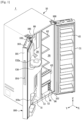
- FIG. 1 is a view illustrating a refrigerator according to an embodiment of the disclosure.
- a refrigerator 1 may include a body 10, a plurality of storage compartments 20 and 30, and a plurality of doors 100 and 31 configured to open and close the plurality of storage compartments 20 and 30.
- the body 10 may include a plurality of inner cases 11 and 12 and an outer case 14 disposed on the outside of the plurality of inner cases 11 and 12 to form an exterior of the refrigerator 1. Between the plurality of inner cases 11 and 12, and the outer case 14, an insulating material (not shown) may foam and be filled to prevent cold air of the plurality of storage compartments 20, and 30 from leaking to the outside of the refrigerator 1.
- the plurality of inner cases 11 and 12 may include a first inner case 11 and a second inner case 12 which are adjacent in a left and right direction Y of the refrigerator 1.
- the first inner case 11 may be disposed on the left side of a partition wall 13 in the left and right direction Y of the refrigerator 1
- the second inner case 12 may be disposed on the right side of the partition wall 13 in the left and right direction Y of the refrigerator 1.
- an insulating material (not shown) may foam and be filled to prevent the heat exchange between a freezing compartment 20 and a refrigerating compartment 30.
- the plurality of storage compartments 20, and 30 may include the freezing compartment 20 provided in the inside of the body 10.
- the plurality of storage compartments 20, and 30 may include the freezing compartment 20 provided in the inside of the first inner case 11.
- the plurality of storage compartments 20, and 30 may further include the refrigerating compartment 30 provided in the inside of the body 10 so as to be adjacent to the freezing compartment 20 in the left and right direction Y of the refrigerator 1.
- the plurality of storage compartments 20, and 30 may further include the refrigerating compartment 30 provided in the inside of the second inner case 12.
- the plurality of storage compartments 20 and 30 may include an open front surface.
- a plurality of shelves 62 and/or a storage box 63 may be provided in the plurality of storage compartments 20 and 30 to store food.
- the storage box 63 may be provided to allow food to be placed and stored therein.
- the storage box 63 may be located in the refrigerating compartment 30.
- the storage box 63 may be withdrawn from the refrigerating compartment 30 or may be inserted into the refrigerating compartment 30.
- the storage box 63 may be configured to be movable in a front and rear direction X of the refrigerator 1.
- the storage box 63 may slide with respect to the refrigerating compartment 30.
- the plurality of doors 100 and 31 may be rotatably installed on the body 10 to open and close the open front surfaces of the plurality of storage compartments 20 and 30.
- the plurality of doors 100 and 31 may include a freezing compartment door 100 rotatably installed on the body 10 to open and close the freezing compartment 20, and a refrigerating compartment door 31 rotatably installed on the body 10 to open and close the refrigerating compartment 30.
- the plurality of doors 100 and 31 may include a door insulating material (not shown) foaming and being filled inside the door to prevent the cold air of the plurality of storage compartments 20 and 30 from leaking to the outside.
- a plurality of door guards 61 may be provided on a rear surface of the plurality of doors 100 and 31 to store food or the like.
- a dispenser 130 is provided on at least one of the plurality of doors 100 and 31 to allow a user to take out water or ice from the outside. Particularly, the dispenser 130 may be provided on the freezing compartment door 100.
- an ice maker 80 configured to make ice that is to be supplied through the dispenser 130 is provided.
- the ice maker 80 may be provided in the freezing compartment 20.
- the refrigerator 1 may further include a cold air supply device configured to supply cold air to the plurality of storage compartments 20 and 30.
- the cold air supply device may include a compressor, a condenser, an expansion valve, and an evaporator.
- the compressor configured to compress a refrigerant and the condenser configured to condense the compressed refrigerant may be installed in a machine room provided below the rear of the plurality of storage compartments 20 and 30.
- a water supply assembly 90 may be disposed in the storage compartments 20, and 30. Particularly, the water supply assembly 90 may be disposed in the refrigerating compartment 30. However, the location of the water supply assembly 90 is not limited thereto.
- the water supply assembly 90 may include a filter 91 configured to filter water that is supplied from an external water source (not shown), and a water tank (not shown) provided to store water that is filtered in the filter 91.
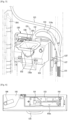
- FIG. 2 is a view illustrating a freezing compartment door shown in FIG. 1 .
- FIG. 3 is a view illustrating a hose guide provided inside the freezing compartment door shown in FIG. 2 .
- FIG. 4 is a view illustrating an inside of a lower end portion of the freezing compartment door shown in FIG. 3 .
- FIG. 5 is a view illustrating an inside of a portion, in which a dispenser is arranged, of the freezing compartment door shown in FIG. 3 .
- FIG. 6 is a view illustrating an upper surface of the freezing compartment door shown in FIG. 3 .
- the freezing compartment door 100 For convenience of description, only the freezing compartment door 100 will be described, but the configurations described below may also be applied to the refrigerating compartment door 31.
- the freezing compartment door 100 is referred to as a door 100.
- the door 100 may include a door plate 101 forming an exterior.
- the door plate 101 may form a front surface and opposite lateral surfaces of the door 100.
- a handle 104 may be formed on one lateral surface of the door plate 101.
- the handle 104 may be recessed from the lateral surface of the door plate 101.
- an upper door cap 102 may be coupled to an upper end of the door plate 101.
- a cap space 102a may be formed inside the upper door cap 102.
- a portion of an ice maker hose 123 may be accommodated in the cap space 102a.
- An upper hinge coupling portion 108 may be provided in the upper door cap 102.
- the upper hinge coupling portion 108 may be rotatably coupled to an upper hinge 106 installed on the body 10.
- the upper hinge 106 may be installed at opposite ends of the upper front side of the body 10.
- a lower door cap 104 may be coupled to a lower end of the door plate 101.
- the lower door cap 104 may include a foam opening 104a. After the door plate 101, the upper door cap 102, the lower door cap 104, and an inner plate 101a are coupled to each other, it is possible to allow an insulating material to foam and to be filled inside the door 100 through the foaming opening 104a.
- a lower hinge coupling portion 109 may be provided on the lower door cap 104.
- the lower hinge coupling portion 109 may be rotatably coupled to a lower hinge 107 installed on the body 10.
- the lower hinge 107 may be installed at opposite ends of the lower front side of the body 10.
- a rear surface of the door plate 101 may be covered by the inner plate 101a.
- the plurality of door guards 61 may be provided on the inner plate 101a.
- the door plate 101 may include a dispenser opening 101b formed on a front surface. A portion of the dispenser 130 may be exposed to the outside through the dispenser opening 101b. A portion of the dispenser cover 135 of the dispenser 130 and a lever 138 may be exposed to the outside through the dispenser opening 101b.
- the dispenser 130 may include an accommodation space 139 formed to accommodate a container.
- a dispenser hose 122 provided to be connectable to the dispenser 130, the ice maker hose 123 provided to be connectable to the ice maker 80, and hose guides 111, 112, and 113 provided to guide the dispenser hose 122 and the ice maker hose 123 are provided.
- the hose guides 111, 112, and 113 include a guide inlet portion 111, a dispenser guide portion 112, and an ice maker guide portion 113.
- the hose guides 111, 112, and 113 are located inside the door 100 and are provided to accommodate the dispenser hose 122 and the ice maker hose 123 therein.
- a door insulating material provided inside the door 100 may be provided to surround the hose guides 111, 112, and 113.
- the hose guides 111, 112, and 113 may be fixed to the inside of the door 100, but the dispenser hose 122 and the ice maker hose 123, which are accommodated in the hose guides 111, 112, and 113, may be separable from the door 100.
- the guide inlet portion 111 guides the dispenser hose 122 and the ice maker hose 123.
- One end of the guide inlet portion 111 may be coupled to the lower hinge coupling portion 109.
- the guide inlet portion 111 may be coupled to the lower hinge 107 through the lower hinge coupling portion 109.
- the other end of the guide inlet portion 111 which is opposite to the one end that is connected to the lower hinge coupling portion 109, may be branched into the dispenser guide portion 112 and the ice maker guide portion 113.
- the dispenser guide portion 112 is provided to guide the dispenser hose 122.
- the dispenser guide portion 112 may extend from the guide inlet portion 111 toward the dispenser 130.
- the dispenser guide portion 112 includes a hose accommodating portion 114 having an inner cross-sectional area greater than an inner cross-sectional area of the guide inlet portion 111 and may have an inner cross-section area greater than an inner cross-sectional area of the ice maker guide portion 113.
- the hose accommodating portion 114 may include a contraction preventing portion 114a provided to prevent contraction caused by the door insulation material filled in the door 100.
- the contraction preventing portion 114a may protrude outward from an outer side of the hose accommodating portion 114.
- the contraction preventing portion 114a may be formed in a portion of the hose accommodating portion 114 in which an area in contact with the door insulating material is relatively large. Strength of the hose accommodating portion 114 may be improved by the contraction preventing portion 114a, and accordingly, it is possible to prevent the hose accommodating portion 114 from being contracted caused by the insulating material that foams and is filled inside the door 100.
- the hose accommodating portion 114 may include a first accommodating portion (a lower portion of the hose accommodating portion 114, refer to FIG. 7 ) in which the dispenser hose 122 is accommodated in response to that the dispenser hose 122 is withdrawn from the dispenser guide portion 112 by a first length, and a second accommodating portion (an upper portion of the hose accommodating portion 114, refer to FIG. 9 ) in which the dispenser hose 122 is accommodated in response to that the dispenser hose 122 is withdrawn from the dispenser guide portion 112 by a second length that is less than the first length.
- a first accommodating portion a lower portion of the hose accommodating portion 114, refer to FIG. 7
- a second accommodating portion an upper portion of the hose accommodating portion 114, refer to FIG. 9
- the dispenser guide portion 112 may be fixed to the dispenser 130. Particularly, the dispenser guide portion 112 may be fixed to a dispenser case 131 of the dispenser 130.
- the hose guides 111, 112, and 113 may include a first coupling portion 116 coupled to one portion of the dispenser 130 and a second coupling portion 117 coupled to another portion of the dispenser 130.
- the first coupling portion 116 may be coupled to a first guide coupling portion 136 formed in an upper portion of the dispenser case 131.
- the first coupling portion 116 may be screwed to the first guide coupling portion 136 through a first fastening member 151.
- the second coupling portion 117 may be coupled to a second guide coupling portion 137 formed on one lateral surface of the dispenser case 131.
- the second guide coupling portion 137 may have a hook shape, and the second coupling portion 117 may be hooked to and fixed to the second guide coupling portion 137.
- the ice maker guide portion 113 is provided to guide the ice maker hose 123.
- the ice maker guide portion 113 may extend from the guide inlet portion 111 toward the upper door cap 102 of the door 100.
- the ice maker guide portion 113 may be connected to an ice maker hose hole 118 formed in the upper door cap 102.
- the ice maker hose 123 may extend into the cap space 102a through the ice maker hose hole 118.
- the ice maker hose 123 which extends to the cap space 102a of the upper door cap 102 through the ice maker hose hole 118, may be connected to an ice maker water supply device 119 of the ice maker 80.
- the ice maker water supply device 119 may receive water required for ice making through the ice maker hose 123.
- the dispenser hose 122 may be provided to guide water to the dispenser 130.
- the dispenser hose 122 may be provided to pass through the lower hinge coupling portion 109 and/or the lower hinge 107.
- the guide inlet portion 111 may be connected to the lower hinge coupling portion 109 and/or the lower hinge 107.
- the dispenser hose 122 extending to the outside of the door 100 through the lower hinge coupling portion 109 and the lower hinge 107 may be connected to a hose (not shown), which extends from the water supply assembly 90, so as to receive water.
- the dispenser hose 122 may extend from a portion, which is branched into the dispenser guide portion 112 and the ice maker guide portion 113 from the guide inlet portion 111, to the dispenser guide portion 112.
- the dispenser hose 122 extending along the dispenser guide portion 112 may be connected to the dispenser 130.
- the ice maker hose 123 may be provided to guide water to the ice maker 80. Referring to FIG. 4 , the ice maker hose 123 may be provided to pass through the lower hinge coupling portion 109 and/or the lower hinge 107. For this, the guide inlet portion 111 may be connected to the lower hinge coupling portion 109 and/or the lower hinge 107. The ice maker hose 123, which extends to the outside of the door 100 through the lower hinge coupling portion 109 and the lower hinge 107, may be connected to a hose (not shown), which extends from the water supply assembly 90, so as to receive water.
- the ice maker hose 123 may extend from a portion, which is branched into the dispenser guide portion 112 and the ice maker guide portion 113 from the guide inlet portion 111, to the ice maker guide portion 113.
- the ice maker hose 123 extending along the ice maker guide portion 113 may extend to the cap space 102a of the upper door cap 102 through the ice maker hose hole 118.
- the ice maker hose 123 may be connected to the ice maker water supply device 119 of the ice maker 80.
- FIG. 7 is a view illustrating a state in which a dispenser hose is connected to the dispenser shown in FIG. 3 .
- FIG. 8 is a view illustrating a state in which a dispenser cover shown in FIG. 7 , a connecting member and an ice guide are being coupled to each other.
- FIG. 9 is a view illustrating a state in which the dispenser cover, the connecting member and the ice guide shown in FIG. 8 are being mounted to a dispenser case and a hose is being connected to the connecting member.
- a process of coupling the dispenser hose 122 to the dispenser 130 of the refrigerator 1 according to an embodiment of the disclosure will be described with reference to FIGS. 7 to 9 .
- the dispenser 130 may include the dispenser case 131 coupled to the rear surface of the door plate 101 of the door 100.
- An ice chute 132 may be coupled to the dispenser case 131.
- the ice chute 132 may guide ice made in the ice maker 80 to the dispenser 130.
- the ice chute 132 may include a chute opening 132a provided to communicate with the ice maker 80.
- the ice chute 132 may include a chute opening and closing member 132b configured to open and close an opening provided to communicate with the dispenser case 132.
- the chute opening and closing member 132b may be driven by a chute driving device 132c.
- a first ice guide 133 may be mounted on the dispenser case 131.
- the first ice guide 133 may guide the ice transmitted from the ice chute 132 to a second ice guide 134.
- the dispenser case 131 may include the second ice guide 134 disposed under the first ice guide 133.
- the second ice guide 134 may guide the ice transmitted from the first ice guide 133 to the accommodation space 139 of the dispenser 130.
- the second ice guide 134 may include a guide opening 134d.
- the second ice guide 134 may include a cover coupling portion 134a coupled to the dispenser cover 135.
- the cover coupling portion 134a may be coupled to the dispenser cover 135 in a hook manner.
- the second ice guide 134 may include a guide fixing portion 134b to which a connecting member 140 is fixed.
- a connecting member insertion hole 134c into which the connecting member 140 is inserted may be formed.
- the dispenser cover 135 may be coupled to the dispenser case 131.
- the dispenser cover 135 may cover the inside of the dispenser 130.
- the connecting member 140 may be mounted on the second ice guide 134.
- the connecting member 140 may include a connecting member fixing portion 149.
- the connecting member fixing portion 149 may be fixed to the guide fixing portion 134b of the second ice guide 134 by a second fastening member 152.
- One end of the connecting member 140 may be connected to the dispenser hose 122.
- a cock 146 may be detachably coupled to the other end of the connecting member 140 opposite to the one end.
- the dispenser hose 122 may include a dispenser connecting portion 122a fixed to the dispenser 130.
- the dispenser connecting portion 122a may be an end portion of the dispenser hose 122 close to the dispenser 130.
- the hose accommodating portion 114 forms a space to allow the dispenser hose 122 to be withdrawn from the dispenser guide portion 112 by a predetermined length. Particularly, for ease of operation of connecting the dispenser hose 122 to the connecting member 140 of the dispenser 130, the dispenser connecting portion 122a of the dispenser hose 122 may be withdrawn from the dispenser guide portion 112 as far as possible. That is, in order to easily couple the dispenser hose 122 to the dispenser 130, the dispenser hose 122 may be withdrawn from the dispenser guide 112 by a length longer than necessary. Accordingly, a portion of the dispenser hose 122 positioned in the hose accommodating portion 114 is positioned in the lower portion of the hose accommodating portion 114.
- the dispenser hose 122 in response to mounting the dispenser cover 135 and the second ice guide 134 to the dispenser case 131 after coupling the dispenser connecting portion 122a of the dispenser hose 122 to the connecting member 140, the dispenser hose 122, which is withdrawn by a length longer than necessary, may be brought back into the dispenser guide portion 112. At this time, in the conventional manner, the dispenser hose 122 may be bent or twisted upon being brought back into the dispenser guide portion 112 because the hose accommodating portion 114 is not provided.
- the hose accommodating portion 114 is provided in the dispenser guide portion 112, and thus the dispenser hose 122 may be accommodated in the hose accommodating portion 114 without being bent or twisted in response to being inserted into the dispenser guide portion 112.
- the dispenser connecting portion 122a of the dispenser hose 122 may be coupled to the connecting member 140, and the cock 146 may be removably provided in the other end of the connecting member 140, thereby reducing the material cost in comparison with the conventional manner in which the dispenser hose 122 extends to the accommodation space 139 of the dispenser 130 and an unnecessary portion is cut out.
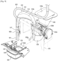
- FIG. 10 is a cross-sectional view illustrating a state in which the dispenser hose and a cock are coupled to the connecting member shown in FIG. 7 .
- FIG. 11 is a view illustrating a state in which the dispenser hose is separated from the connecting member shown in FIG. 10 .
- FIG. 12 is a view illustrating a state in which the cock is separated from the dispenser shown in FIG. 3 .
- the cock 146 detachably mounted on the connecting member 140 of the dispenser 130 of the refrigerator 1 according to an embodiment of the disclosure will be described with reference to FIGS. 10 to 12 .
- the cock 146 according to an embodiment of the disclosure is shown to be applied to a side by side (SBS) type refrigerator 1, the cock 146 according to an embodiment of the disclosure is not limited to the type of refrigerator.
- the cock 146 according to an embodiment of the disclosure may be applied to any type of refrigerator as long as including a dispenser.
- the cock 146 is a component separated from the above-mentioned hose guides 111, 112 and 113 and thus the cock 146 may be applied to a refrigerator in which the hose guides 111, 112 and 113 are not provided.
- the dispenser 130 includes the connecting member 140 provided to connect the dispenser hose 122 to the cock 146.
- the connecting member 140 is provided such that one end of the dispenser hose 122 may be fixed to the dispenser connecting portion 122a.
- the connecting member 140 may include a first hose fixing member 141 provided to fix the dispenser hose 122 by an elastic force.
- the first hose fixing member 141 may be provided as an 0-ring.
- the first hose fixing member 141 may seal between the connecting member 140 and the dispenser hose 122.
- the connecting member 140 may include a second hose fixing member 143 provided to selectively fix the dispenser hose 122.
- the second hose fixing member 143 may be configured to release the dispenser hose 122 in response to pressing the second hose fixing member 143 to the direction in which the dispenser hose 122 is inserted into the connecting member 140.
- the second hose fixing member 143 is provided in such a way that one end thereof close to the first hose fixing member 141 is elastically biased in a direction of fixing the dispenser hose 122.
- the cock 146 may be provided to be separable from the connecting member 140.
- the cock 146 may be formed of stainless steel.
- the connecting member 140 may include a cock fixing member 147 provided to removably fix the cock 146.
- the cock fixing member 147 may fix the cock 146 by an elastic force.
- the cock fixing member 147 may be provided as an O-ring.
- the cleanliness of the dispenser 130 may be improved.
Landscapes
- Engineering & Computer Science (AREA)
- Physics & Mathematics (AREA)
- Mechanical Engineering (AREA)
- Thermal Sciences (AREA)
- General Engineering & Computer Science (AREA)
- Chemical & Material Sciences (AREA)
- Combustion & Propulsion (AREA)
- Refrigerator Housings (AREA)
- Devices For Dispensing Beverages (AREA)
- Devices That Are Associated With Refrigeration Equipment (AREA)
Claims (12)
- Kühlschrank (1), der Folgendes umfasst:einen Körper (10), der ein Lagerfach (20, 30) ausbildet;eine Tür (31, 100), die drehbar am Körper (10) angebracht ist, um das Lagerfach (20, 30) zu öffnen oder zu schließen;einen Spender (130) in der Tür (31, 100);eine Eisbereiter (80) im Lagerfach (20, 30);einen Spenderschlauch (122), der mit dem Spender (130) verbindbar ist;einen Eisbereiterschlauch (123), der mit dem Eisbereiter (80) verbunden werden kann; undeine Schlauchführung (111, 112, 113),durch die der Spenderschlauch (122) einführbar ist, um zum Spender (130) geführt zu werden, um mit dem Spender (130) verbunden zu werden, und in der der Spenderschlauch (122), wenn er mit dem Spender (130) verbunden ist, aufgenommen ist, und
durch die der Eisbereiterschlauch (123) einführbar ist, um zu dem Eisbereiter (80) geführt zu werden, um mit dem Eisbereiter (80) verbunden zu werden, und in der der Eisbereiterschlauch (123), wenn er mit dem Eisbereiter (80) verbunden ist, aufgenommen ist, wobei die Schlauchführung (111, 112, 113) umfasst:einen Führungseinlassabschnitt (111), durch den der Spenderschlauch (122) und der Eisbereiterschlauch (123) eingeführt werden können, um den Spenderschlauch (122) und den Eisbereiterschlauch (123) zu führen,einen Spenderführungsabschnitt (112), der von dem Führungseinlassabschnitt (111) abzweigt, um den Spenderschlauch (122), aber nicht den Eisbereiterschlauch (123) zu führen, undeinen Eisbereiterführungsabschnitt (113), der von dem Führungseinlassabschnitt (111) abzweigt, um den Eisbereiterschlauch (123), aber nicht den Spenderschlauch (122) zu führen, undwobei der Spenderführungsabschnitt (112) einen Schlauchaufnahmeabschnitt (114) umfasst, der einen Raum ausbildet, um zu ermöglichen, dass der Spenderschlauch (122) um eine vorbestimmte Länge aus dem Spenderführungsabschnitt (112) herausgezogen werden kann,dadurch gekennzeichnet, dass die Schlauchführung (111, 112, 113) im Inneren der Tür (31, 100) vorgesehen ist und dass der Schlauchaufnahmeabschnitt (114) so ausgebildet ist, dass er eine innere Querschnittsfläche aufweist, die größer ist als eine innere Querschnittsfläche des Führungseinlassabschnitts (111). - Kühlschrank (1) nach Anspruch 1, der außerdem Folgendes umfasst:ein Scharnier, das die Tür (31, 100) drehbar trägt,wobei der Führungseinlassabschnitt (111) mit dem Scharnier gekoppelt ist.
- Kühlschrank (1) nach Anspruch 1, wobei der Schlauchaufnahmeabschnitt (114) einen Kontraktionsverhinderungsabschnitt (114a) enthält, der von einer Außenfläche des Schlauchaufnahmeabschnitts (114) vorsteht.
- Kühlschrank (1) nach Anspruch 1, wobeider Spenderschlauch (122) einen Spenderverbindungsabschnitt (122a) aufweist, der an dem Spender (130) befestigbar ist, undder Schlauchaufnahmeabschnitt (114) umfasst:einen ersten Aufnahmeabschnitt, in dem der Spenderschlauch (122) in Reaktion darauf angeordnet wird, dass der Spenderverbindungsabschnitt (122a) um eine erste Länge aus dem Spenderführungsabschnitt (112) herausgezogen wird, undeinen zweiten Aufnahmeabschnitt, in dem der Spenderschlauch (122) in Reaktion darauf angeordnet wird, dass der Spenderverbindungsabschnitt (122a) um eine zweite Länge, die kleiner als die erste Länge ist, aus dem Spenderführungsabschnitt (112) herausgezogen wird.
- Kühlschrank (1) nach Anspruch 1, wobei die Schlauchführung (111, 112, 113) am Spender (130) befestigt ist.
- Kühlschrank (1) nach Anspruch 5, wobei die Schlauchführung (111, 112, 113) umfasst:einen ersten Kopplungsabschnitt (116), der mit einem Abschnitt des Spenders (130) verschraubt ist, undeinen zweiten Kopplungsabschnitt (117), der mit einem anderen Abschnitt des Spenders (130) verbunden ist.
- Kühlschrank (1) nach Anspruch 1, wobei die Tür (31, 100) ein Isoliermaterial aufweist, das die Schlauchführung (111, 112, 113) umgibt.
- Kühlschrank (1) nach Anspruch 1, wobei der Spender (130) umfasst:ein Verbindungselement (140), dessen eines Ende mit dem Spenderschlauch (122) verbunden ist, undeinen Hahn (146), der abnehmbar mit einem anderen Ende des Verbindungselements (140) gekoppelt ist, das dem einen Ende des Verbindungselements (140) gegenüberliegt.
- Kühlschrank (1) nach Anspruch 8, wobei das Verbindungselement (140) ein Hahnbefestigungselement (147) enthält, um den Hahn (146) durch eine elastische Kraft zu befestigen.
- Kühlschrank (1) nach Anspruch 8, wobei das Verbindungselement (140) umfasst:ein erstes Schlauchbefestigungselement (141), um den Spenderschlauch (122) durch eine elastische Kraft zu befestigen, undein zweites Schlauchbefestigungselement (143), das konfiguriert ist, um den Spenderschlauch (122) in Reaktion darauf freizugeben, dass das zweite Schlauchbefestigungselement (143) in eine Richtung gedrückt wird, die einer Richtung entgegengesetzt ist, aus der der Spenderschlauch (122) von dem Verbindungselement (140) freigegeben wird.
- Kühlschrank (1) nach Anspruch 8, wobei der Spender (130) eine Eisführung aufweist, an der das Verbindungselement (140) angebracht ist, um Eis aus dem Eisbereiter (80) zu führen.
- Kühlschrank (1) nach Anspruch 9, wobei der Spender (130) eine Spenderabdeckung (135) aufweist, an die die Eisführung abnehmbar gekoppelt ist.
Applications Claiming Priority (2)
| Application Number | Priority Date | Filing Date | Title |
|---|---|---|---|
| KR1020200025170A KR102902153B1 (ko) | 2020-02-28 | 2020-02-28 | 냉장고 |
| PCT/KR2021/002195 WO2021172830A1 (en) | 2020-02-28 | 2021-02-22 | Refrigerator |
Publications (4)
| Publication Number | Publication Date |
|---|---|
| EP4025852A1 EP4025852A1 (de) | 2022-07-13 |
| EP4025852A4 EP4025852A4 (de) | 2022-11-02 |
| EP4025852B1 true EP4025852B1 (de) | 2024-08-28 |
| EP4025852C0 EP4025852C0 (de) | 2024-08-28 |
Family
ID=77463595
Family Applications (1)
| Application Number | Title | Priority Date | Filing Date |
|---|---|---|---|
| EP21761210.0A Active EP4025852B1 (de) | 2020-02-28 | 2021-02-22 | Kühlschrank |
Country Status (4)
| Country | Link |
|---|---|
| US (2) | US11828527B2 (de) |
| EP (1) | EP4025852B1 (de) |
| KR (1) | KR102902153B1 (de) |
| WO (1) | WO2021172830A1 (de) |
Families Citing this family (2)
| Publication number | Priority date | Publication date | Assignee | Title |
|---|---|---|---|---|
| KR20230094440A (ko) * | 2021-12-21 | 2023-06-28 | 엘지전자 주식회사 | 냉장고 |
| KR20230094441A (ko) * | 2021-12-21 | 2023-06-28 | 엘지전자 주식회사 | 냉장고 |
Family Cites Families (40)
| Publication number | Priority date | Publication date | Assignee | Title |
|---|---|---|---|---|
| KR970022171A (ko) | 1995-10-31 | 1997-05-28 | 김광호 | 제빙기 및 워터디스펜서를 구비한 냉장고 |
| KR200157107Y1 (ko) | 1997-06-02 | 1999-09-15 | 윤종용 | 냉장고용 디스펜서의 냉수공급튜브 연결장치 |
| US5787724A (en) | 1997-06-04 | 1998-08-04 | Maytag Corporation | Dispensing assembly for top mount refrigerator |
| KR20000011251U (ko) | 1998-11-30 | 2000-06-26 | 전주범 | 사이드 바이 사이드형 냉장고의 물공급장치 |
| DE102004013431B4 (de) | 2003-03-20 | 2018-06-21 | Lg Electronics Inc. | Kühlschranktür |
| US7266951B2 (en) * | 2004-10-26 | 2007-09-11 | Whirlpool Corporation | Ice making and dispensing system |
| US7287555B2 (en) * | 2005-11-30 | 2007-10-30 | Bsh Bosch Und Siemens Hausgeraete Gmbh | Dispenser assembly for a refrigerator door |
| KR100728340B1 (ko) | 2005-12-12 | 2007-06-13 | 주식회사 대우일렉트로닉스 | 냉장고용 음료 취출 장치의 배관구조 |
| CA3247024A1 (en) | 2006-07-07 | 2025-03-27 | Fairlife, L.L.C. | Liquid food dispenser system and method |
| KR101334576B1 (ko) * | 2006-09-15 | 2013-11-28 | 엘지전자 주식회사 | 냉장고 제빙수단 |
| KR101548263B1 (ko) | 2008-10-02 | 2015-08-28 | 삼성전자 주식회사 | 냉장고 |
| KR20100053978A (ko) * | 2008-11-13 | 2010-05-24 | 삼성전자주식회사 | 냉장고 |
| CN104764265B (zh) * | 2008-11-14 | 2018-04-10 | 博西华家用电器有限公司 | 冰箱及其制造方法 |
| US8136367B2 (en) * | 2008-12-11 | 2012-03-20 | General Electric Company | Hinge assembly for a refrigerator |
| KR101626981B1 (ko) | 2009-06-22 | 2016-06-02 | 엘지전자 주식회사 | 냉장고의 제어 방법 |
| KR20110026602A (ko) | 2009-09-08 | 2011-03-16 | 삼성전자주식회사 | 냉장고 |
| KR101733241B1 (ko) | 2010-03-15 | 2017-05-08 | 엘지전자 주식회사 | 냉장고 |
| KR101821813B1 (ko) * | 2010-09-20 | 2018-03-09 | 엘지전자 주식회사 | 냉장고 |
| KR101849106B1 (ko) | 2011-08-23 | 2018-06-01 | 삼성전자주식회사 | 냉장고 |
| KR20130059988A (ko) * | 2011-11-29 | 2013-06-07 | 삼성전자주식회사 | 냉장고 |
| KR101837451B1 (ko) * | 2011-11-29 | 2018-03-12 | 삼성전자주식회사 | 냉장고 |
| KR101892755B1 (ko) * | 2012-05-16 | 2018-08-28 | 엘지전자 주식회사 | 냉장고 |
| EP3062049B1 (de) * | 2013-02-20 | 2017-12-13 | LG Electronics Inc. | Kühlschrank |
| KR102156123B1 (ko) * | 2013-08-12 | 2020-09-15 | 엘지전자 주식회사 | 냉장고 |
| KR102186837B1 (ko) | 2013-12-06 | 2020-12-07 | 삼성전자주식회사 | 냉장고 |
| KR101561349B1 (ko) * | 2013-12-13 | 2015-10-16 | 동부대우전자 주식회사 | 냉장고 급수장치 |
| KR101696850B1 (ko) * | 2015-06-17 | 2017-01-16 | 동부대우전자 주식회사 | 아이스버킷 록킹장치를 갖는 냉장고 및 아이스버킷 록킹장치의 설치 방법 |
| US9739517B2 (en) * | 2015-08-21 | 2017-08-22 | Haier Us Appliance Solutions, Inc. | Controlling the operation of a dispenser system |
| DE102015217566A1 (de) * | 2015-09-15 | 2017-03-16 | BSH Hausgeräte GmbH | Kältegerät mit einem Eisbehälter |
| KR102432001B1 (ko) * | 2015-10-14 | 2022-08-16 | 삼성전자주식회사 | 냉장고 |
| KR20170069658A (ko) * | 2015-12-11 | 2017-06-21 | 삼성전자주식회사 | 냉장고 |
| US9738504B2 (en) * | 2015-12-17 | 2017-08-22 | Whirlpool Corporation | Low force actuation dispenser paddle for a dispenser assembly of an appliance |
| KR102465860B1 (ko) * | 2015-12-24 | 2022-11-11 | 삼성전자주식회사 | 냉장고 |
| KR101798542B1 (ko) | 2016-07-12 | 2017-11-17 | 동부대우전자 주식회사 | 아이스 메이커를 갖는 냉장고 및 급수유닛 |
| KR102519052B1 (ko) | 2016-07-19 | 2023-04-07 | 삼성전자주식회사 | 밸브 장치 및 이를 갖는 냉장고 |
| KR101997259B1 (ko) * | 2017-05-26 | 2019-10-01 | 엘지전자 주식회사 | 냉장고 |
| KR102474197B1 (ko) | 2017-07-21 | 2022-12-06 | 엘지전자 주식회사 | 냉장고 |
| US10837690B2 (en) * | 2017-12-08 | 2020-11-17 | Midea Group Co., Ltd. | Refrigerator icemaking system with tandem storage bins and/or removable dispenser recess |
| KR20190125113A (ko) * | 2018-04-27 | 2019-11-06 | 주식회사 위니아대우 | 제빙 장치 및 이를 갖는 냉장고 |
| BR102019015737A2 (pt) * | 2018-08-01 | 2020-02-18 | Lg Electronics Inc. | Refrigerador |
-
2020
- 2020-02-28 KR KR1020200025170A patent/KR102902153B1/ko active Active
-
2021
- 2021-02-22 WO PCT/KR2021/002195 patent/WO2021172830A1/en not_active Ceased
- 2021-02-22 EP EP21761210.0A patent/EP4025852B1/de active Active
- 2021-03-01 US US17/188,237 patent/US11828527B2/en active Active
-
2023
- 2023-10-24 US US18/383,369 patent/US12173960B2/en active Active
Also Published As
| Publication number | Publication date |
|---|---|
| US11828527B2 (en) | 2023-11-28 |
| US20210270517A1 (en) | 2021-09-02 |
| US20240053093A1 (en) | 2024-02-15 |
| WO2021172830A1 (en) | 2021-09-02 |
| US12173960B2 (en) | 2024-12-24 |
| KR102902153B1 (ko) | 2025-12-19 |
| EP4025852C0 (de) | 2024-08-28 |
| EP4025852A1 (de) | 2022-07-13 |
| KR20210109925A (ko) | 2021-09-07 |
| EP4025852A4 (de) | 2022-11-02 |
Similar Documents
| Publication | Publication Date | Title |
|---|---|---|
| US9360239B2 (en) | Refrigerator | |
| US8438871B2 (en) | Refrigerator door having dispenser | |
| US12173960B2 (en) | Refrigerator | |
| RU2608220C1 (ru) | Скользящее устройство и холодильник, имеющий скользящее устройство | |
| KR101067219B1 (ko) | 냉장고 | |
| EP4018140B1 (de) | Kühlschrank | |
| EP4321826A1 (de) | Kühlschrank | |
| EP4202331A1 (de) | Kühlschrank | |
| EP2348268B1 (de) | Kühlgerät und dessen herstellungsmethode | |
| US20220196312A1 (en) | Refrigerator | |
| EP4585873A1 (de) | Kühlschrank | |
| EP3667205B1 (de) | Kühlschrank | |
| KR20240030126A (ko) | 냉장고 | |
| US20220243973A1 (en) | Refrigerator and method for manufacturing same | |
| KR101053849B1 (ko) | 냉장고 | |
| US20220357093A1 (en) | Refrigerator | |
| KR100688672B1 (ko) | 냉장실도어 | |
| KR0133006Y1 (ko) | 냉장고용 얼음저장용기 | |
| KR100951286B1 (ko) | 냉장고 | |
| JP2006105420A (ja) | 自動製氷機及び自動製氷機を備えた冷凍冷蔵庫 | |
| US20220373248A1 (en) | Refrigerator | |
| US20240085088A1 (en) | Refrigerator | |
| US20220357096A1 (en) | Refrigerator | |
| US20220196314A1 (en) | Refrigerator | |
| KR100662140B1 (ko) | 냉장고 이너케이스의 처짐방지 구조 |
Legal Events
| Date | Code | Title | Description |
|---|---|---|---|
| STAA | Information on the status of an ep patent application or granted ep patent |
Free format text: STATUS: THE INTERNATIONAL PUBLICATION HAS BEEN MADE |
|
| PUAI | Public reference made under article 153(3) epc to a published international application that has entered the european phase |
Free format text: ORIGINAL CODE: 0009012 |
|
| STAA | Information on the status of an ep patent application or granted ep patent |
Free format text: STATUS: REQUEST FOR EXAMINATION WAS MADE |
|
| 17P | Request for examination filed |
Effective date: 20220404 |
|
| AK | Designated contracting states |
Kind code of ref document: A1 Designated state(s): AL AT BE BG CH CY CZ DE DK EE ES FI FR GB GR HR HU IE IS IT LI LT LU LV MC MK MT NL NO PL PT RO RS SE SI SK SM TR |
|
| A4 | Supplementary search report drawn up and despatched |
Effective date: 20220929 |
|
| RIC1 | Information provided on ipc code assigned before grant |
Ipc: F25C 5/20 20180101ALI20220923BHEP Ipc: F25C 1/25 20180101ALI20220923BHEP Ipc: F25C 1/24 20180101ALI20220923BHEP Ipc: F25D 23/12 20060101ALI20220923BHEP Ipc: F25D 23/02 20060101AFI20220923BHEP |
|
| DAV | Request for validation of the european patent (deleted) | ||
| DAX | Request for extension of the european patent (deleted) | ||
| GRAP | Despatch of communication of intention to grant a patent |
Free format text: ORIGINAL CODE: EPIDOSNIGR1 |
|
| STAA | Information on the status of an ep patent application or granted ep patent |
Free format text: STATUS: GRANT OF PATENT IS INTENDED |
|
| INTG | Intention to grant announced |
Effective date: 20240416 |
|
| GRAS | Grant fee paid |
Free format text: ORIGINAL CODE: EPIDOSNIGR3 |
|
| GRAA | (expected) grant |
Free format text: ORIGINAL CODE: 0009210 |
|
| STAA | Information on the status of an ep patent application or granted ep patent |
Free format text: STATUS: THE PATENT HAS BEEN GRANTED |
|
| AK | Designated contracting states |
Kind code of ref document: B1 Designated state(s): AL AT BE BG CH CY CZ DE DK EE ES FI FR GB GR HR HU IE IS IT LI LT LU LV MC MK MT NL NO PL PT RO RS SE SI SK SM TR |
|
| REG | Reference to a national code |
Ref country code: CH Ref legal event code: EP |
|
| REG | Reference to a national code |
Ref country code: DE Ref legal event code: R096 Ref document number: 602021018013 Country of ref document: DE |
|
| REG | Reference to a national code |
Ref country code: IE Ref legal event code: FG4D |
|
| U01 | Request for unitary effect filed |
Effective date: 20240919 |
|
| U07 | Unitary effect registered |
Designated state(s): AT BE BG DE DK EE FI FR IT LT LU LV MT NL PT RO SE SI Effective date: 20241011 |
|
| PG25 | Lapsed in a contracting state [announced via postgrant information from national office to epo] |
Ref country code: NO Free format text: LAPSE BECAUSE OF FAILURE TO SUBMIT A TRANSLATION OF THE DESCRIPTION OR TO PAY THE FEE WITHIN THE PRESCRIBED TIME-LIMIT Effective date: 20241128 |
|
| PG25 | Lapsed in a contracting state [announced via postgrant information from national office to epo] |
Ref country code: PL Free format text: LAPSE BECAUSE OF FAILURE TO SUBMIT A TRANSLATION OF THE DESCRIPTION OR TO PAY THE FEE WITHIN THE PRESCRIBED TIME-LIMIT Effective date: 20240828 Ref country code: GR Free format text: LAPSE BECAUSE OF FAILURE TO SUBMIT A TRANSLATION OF THE DESCRIPTION OR TO PAY THE FEE WITHIN THE PRESCRIBED TIME-LIMIT Effective date: 20241129 |
|
| PG25 | Lapsed in a contracting state [announced via postgrant information from national office to epo] |
Ref country code: IS Free format text: LAPSE BECAUSE OF FAILURE TO SUBMIT A TRANSLATION OF THE DESCRIPTION OR TO PAY THE FEE WITHIN THE PRESCRIBED TIME-LIMIT Effective date: 20241228 |
|
| PG25 | Lapsed in a contracting state [announced via postgrant information from national office to epo] |
Ref country code: HR Free format text: LAPSE BECAUSE OF FAILURE TO SUBMIT A TRANSLATION OF THE DESCRIPTION OR TO PAY THE FEE WITHIN THE PRESCRIBED TIME-LIMIT Effective date: 20240828 |
|
| PG25 | Lapsed in a contracting state [announced via postgrant information from national office to epo] |
Ref country code: RS Free format text: LAPSE BECAUSE OF FAILURE TO SUBMIT A TRANSLATION OF THE DESCRIPTION OR TO PAY THE FEE WITHIN THE PRESCRIBED TIME-LIMIT Effective date: 20241128 Ref country code: ES Free format text: LAPSE BECAUSE OF FAILURE TO SUBMIT A TRANSLATION OF THE DESCRIPTION OR TO PAY THE FEE WITHIN THE PRESCRIBED TIME-LIMIT Effective date: 20240828 |
|
| PG25 | Lapsed in a contracting state [announced via postgrant information from national office to epo] |
Ref country code: RS Free format text: LAPSE BECAUSE OF FAILURE TO SUBMIT A TRANSLATION OF THE DESCRIPTION OR TO PAY THE FEE WITHIN THE PRESCRIBED TIME-LIMIT Effective date: 20241128 Ref country code: PL Free format text: LAPSE BECAUSE OF FAILURE TO SUBMIT A TRANSLATION OF THE DESCRIPTION OR TO PAY THE FEE WITHIN THE PRESCRIBED TIME-LIMIT Effective date: 20240828 Ref country code: NO Free format text: LAPSE BECAUSE OF FAILURE TO SUBMIT A TRANSLATION OF THE DESCRIPTION OR TO PAY THE FEE WITHIN THE PRESCRIBED TIME-LIMIT Effective date: 20241128 Ref country code: IS Free format text: LAPSE BECAUSE OF FAILURE TO SUBMIT A TRANSLATION OF THE DESCRIPTION OR TO PAY THE FEE WITHIN THE PRESCRIBED TIME-LIMIT Effective date: 20241228 Ref country code: HR Free format text: LAPSE BECAUSE OF FAILURE TO SUBMIT A TRANSLATION OF THE DESCRIPTION OR TO PAY THE FEE WITHIN THE PRESCRIBED TIME-LIMIT Effective date: 20240828 Ref country code: GR Free format text: LAPSE BECAUSE OF FAILURE TO SUBMIT A TRANSLATION OF THE DESCRIPTION OR TO PAY THE FEE WITHIN THE PRESCRIBED TIME-LIMIT Effective date: 20241129 Ref country code: ES Free format text: LAPSE BECAUSE OF FAILURE TO SUBMIT A TRANSLATION OF THE DESCRIPTION OR TO PAY THE FEE WITHIN THE PRESCRIBED TIME-LIMIT Effective date: 20240828 |
|
| U20 | Renewal fee for the european patent with unitary effect paid |
Year of fee payment: 5 Effective date: 20250221 |
|
| PG25 | Lapsed in a contracting state [announced via postgrant information from national office to epo] |
Ref country code: SM Free format text: LAPSE BECAUSE OF FAILURE TO SUBMIT A TRANSLATION OF THE DESCRIPTION OR TO PAY THE FEE WITHIN THE PRESCRIBED TIME-LIMIT Effective date: 20240828 |
|
| PG25 | Lapsed in a contracting state [announced via postgrant information from national office to epo] |
Ref country code: CZ Free format text: LAPSE BECAUSE OF FAILURE TO SUBMIT A TRANSLATION OF THE DESCRIPTION OR TO PAY THE FEE WITHIN THE PRESCRIBED TIME-LIMIT Effective date: 20240828 |
|
| PG25 | Lapsed in a contracting state [announced via postgrant information from national office to epo] |
Ref country code: SK Free format text: LAPSE BECAUSE OF FAILURE TO SUBMIT A TRANSLATION OF THE DESCRIPTION OR TO PAY THE FEE WITHIN THE PRESCRIBED TIME-LIMIT Effective date: 20240828 |
|
| PGFP | Annual fee paid to national office [announced via postgrant information from national office to epo] |
Ref country code: GB Payment date: 20250120 Year of fee payment: 5 |
|
| PLBE | No opposition filed within time limit |
Free format text: ORIGINAL CODE: 0009261 |
|
| STAA | Information on the status of an ep patent application or granted ep patent |
Free format text: STATUS: NO OPPOSITION FILED WITHIN TIME LIMIT |
|
| 26N | No opposition filed |
Effective date: 20250530 |
|
| PG25 | Lapsed in a contracting state [announced via postgrant information from national office to epo] |
Ref country code: MC Free format text: LAPSE BECAUSE OF FAILURE TO SUBMIT A TRANSLATION OF THE DESCRIPTION OR TO PAY THE FEE WITHIN THE PRESCRIBED TIME-LIMIT Effective date: 20240828 |
|
| REG | Reference to a national code |
Ref country code: CH Ref legal event code: PL |
|
| PG25 | Lapsed in a contracting state [announced via postgrant information from national office to epo] |
Ref country code: CH Free format text: LAPSE BECAUSE OF NON-PAYMENT OF DUE FEES Effective date: 20250228 |
|
| PG25 | Lapsed in a contracting state [announced via postgrant information from national office to epo] |
Ref country code: IE Free format text: LAPSE BECAUSE OF NON-PAYMENT OF DUE FEES Effective date: 20250222 |