EP4023979A1 - Verstärkungsanordnung für eine isolierte struktur - Google Patents
Verstärkungsanordnung für eine isolierte struktur Download PDFInfo
- Publication number
- EP4023979A1 EP4023979A1 EP21216701.9A EP21216701A EP4023979A1 EP 4023979 A1 EP4023979 A1 EP 4023979A1 EP 21216701 A EP21216701 A EP 21216701A EP 4023979 A1 EP4023979 A1 EP 4023979A1
- Authority
- EP
- European Patent Office
- Prior art keywords
- wrapper
- operably coupled
- perimeter frame
- appliance
- insulated structure
- Prior art date
- Legal status (The legal status is an assumption and is not a legal conclusion. Google has not performed a legal analysis and makes no representation as to the accuracy of the status listed.)
- Pending
Links
Images




Classifications
-
- F—MECHANICAL ENGINEERING; LIGHTING; HEATING; WEAPONS; BLASTING
- F25—REFRIGERATION OR COOLING; COMBINED HEATING AND REFRIGERATION SYSTEMS; HEAT PUMP SYSTEMS; MANUFACTURE OR STORAGE OF ICE; LIQUEFACTION SOLIDIFICATION OF GASES
- F25D—REFRIGERATORS; COLD ROOMS; ICE-BOXES; COOLING OR FREEZING APPARATUS NOT OTHERWISE PROVIDED FOR
- F25D23/00—General constructional features
- F25D23/06—Walls
- F25D23/062—Walls defining a cabinet
-
- F—MECHANICAL ENGINEERING; LIGHTING; HEATING; WEAPONS; BLASTING
- F25—REFRIGERATION OR COOLING; COMBINED HEATING AND REFRIGERATION SYSTEMS; HEAT PUMP SYSTEMS; MANUFACTURE OR STORAGE OF ICE; LIQUEFACTION SOLIDIFICATION OF GASES
- F25D—REFRIGERATORS; COLD ROOMS; ICE-BOXES; COOLING OR FREEZING APPARATUS NOT OTHERWISE PROVIDED FOR
- F25D23/00—General constructional features
- F25D23/06—Walls
- F25D23/065—Details
- F25D23/066—Liners
-
- F—MECHANICAL ENGINEERING; LIGHTING; HEATING; WEAPONS; BLASTING
- F25—REFRIGERATION OR COOLING; COMBINED HEATING AND REFRIGERATION SYSTEMS; HEAT PUMP SYSTEMS; MANUFACTURE OR STORAGE OF ICE; LIQUEFACTION SOLIDIFICATION OF GASES
- F25D—REFRIGERATORS; COLD ROOMS; ICE-BOXES; COOLING OR FREEZING APPARATUS NOT OTHERWISE PROVIDED FOR
- F25D23/00—General constructional features
- F25D23/02—Doors; Covers
- F25D23/028—Details
-
- F—MECHANICAL ENGINEERING; LIGHTING; HEATING; WEAPONS; BLASTING
- F25—REFRIGERATION OR COOLING; COMBINED HEATING AND REFRIGERATION SYSTEMS; HEAT PUMP SYSTEMS; MANUFACTURE OR STORAGE OF ICE; LIQUEFACTION SOLIDIFICATION OF GASES
- F25D—REFRIGERATORS; COLD ROOMS; ICE-BOXES; COOLING OR FREEZING APPARATUS NOT OTHERWISE PROVIDED FOR
- F25D23/00—General constructional features
- F25D23/06—Walls
- F25D23/065—Details
- F25D23/067—Supporting elements
-
- F—MECHANICAL ENGINEERING; LIGHTING; HEATING; WEAPONS; BLASTING
- F25—REFRIGERATION OR COOLING; COMBINED HEATING AND REFRIGERATION SYSTEMS; HEAT PUMP SYSTEMS; MANUFACTURE OR STORAGE OF ICE; LIQUEFACTION SOLIDIFICATION OF GASES
- F25D—REFRIGERATORS; COLD ROOMS; ICE-BOXES; COOLING OR FREEZING APPARATUS NOT OTHERWISE PROVIDED FOR
- F25D2201/00—Insulation
- F25D2201/10—Insulation with respect to heat
- F25D2201/12—Insulation with respect to heat using an insulating packing material
-
- F—MECHANICAL ENGINEERING; LIGHTING; HEATING; WEAPONS; BLASTING
- F25—REFRIGERATION OR COOLING; COMBINED HEATING AND REFRIGERATION SYSTEMS; HEAT PUMP SYSTEMS; MANUFACTURE OR STORAGE OF ICE; LIQUEFACTION SOLIDIFICATION OF GASES
- F25D—REFRIGERATORS; COLD ROOMS; ICE-BOXES; COOLING OR FREEZING APPARATUS NOT OTHERWISE PROVIDED FOR
- F25D2201/00—Insulation
- F25D2201/10—Insulation with respect to heat
- F25D2201/14—Insulation with respect to heat using subatmospheric pressure
-
- F—MECHANICAL ENGINEERING; LIGHTING; HEATING; WEAPONS; BLASTING
- F25—REFRIGERATION OR COOLING; COMBINED HEATING AND REFRIGERATION SYSTEMS; HEAT PUMP SYSTEMS; MANUFACTURE OR STORAGE OF ICE; LIQUEFACTION SOLIDIFICATION OF GASES
- F25D—REFRIGERATORS; COLD ROOMS; ICE-BOXES; COOLING OR FREEZING APPARATUS NOT OTHERWISE PROVIDED FOR
- F25D2323/00—General constructional features not provided for in other groups of this subclass
- F25D2323/02—Details of doors or covers not otherwise covered
- F25D2323/024—Door hinges
-
- F—MECHANICAL ENGINEERING; LIGHTING; HEATING; WEAPONS; BLASTING
- F25—REFRIGERATION OR COOLING; COMBINED HEATING AND REFRIGERATION SYSTEMS; HEAT PUMP SYSTEMS; MANUFACTURE OR STORAGE OF ICE; LIQUEFACTION SOLIDIFICATION OF GASES
- F25D—REFRIGERATORS; COLD ROOMS; ICE-BOXES; COOLING OR FREEZING APPARATUS NOT OTHERWISE PROVIDED FOR
- F25D2323/00—General constructional features not provided for in other groups of this subclass
- F25D2323/06—Details of walls not otherwise covered
-
- F—MECHANICAL ENGINEERING; LIGHTING; HEATING; WEAPONS; BLASTING
- F25—REFRIGERATION OR COOLING; COMBINED HEATING AND REFRIGERATION SYSTEMS; HEAT PUMP SYSTEMS; MANUFACTURE OR STORAGE OF ICE; LIQUEFACTION SOLIDIFICATION OF GASES
- F25D—REFRIGERATORS; COLD ROOMS; ICE-BOXES; COOLING OR FREEZING APPARATUS NOT OTHERWISE PROVIDED FOR
- F25D2400/00—General features of, or devices for refrigerators, cold rooms, ice-boxes, or for cooling or freezing apparatus not covered by any other subclass
- F25D2400/04—Refrigerators with a horizontal mullion
-
- F—MECHANICAL ENGINEERING; LIGHTING; HEATING; WEAPONS; BLASTING
- F25—REFRIGERATION OR COOLING; COMBINED HEATING AND REFRIGERATION SYSTEMS; HEAT PUMP SYSTEMS; MANUFACTURE OR STORAGE OF ICE; LIQUEFACTION SOLIDIFICATION OF GASES
- F25D—REFRIGERATORS; COLD ROOMS; ICE-BOXES; COOLING OR FREEZING APPARATUS NOT OTHERWISE PROVIDED FOR
- F25D2400/00—General features of, or devices for refrigerators, cold rooms, ice-boxes, or for cooling or freezing apparatus not covered by any other subclass
- F25D2400/06—Refrigerators with a vertical mullion
-
- Y—GENERAL TAGGING OF NEW TECHNOLOGICAL DEVELOPMENTS; GENERAL TAGGING OF CROSS-SECTIONAL TECHNOLOGIES SPANNING OVER SEVERAL SECTIONS OF THE IPC; TECHNICAL SUBJECTS COVERED BY FORMER USPC CROSS-REFERENCE ART COLLECTIONS [XRACs] AND DIGESTS
- Y02—TECHNOLOGIES OR APPLICATIONS FOR MITIGATION OR ADAPTATION AGAINST CLIMATE CHANGE
- Y02B—CLIMATE CHANGE MITIGATION TECHNOLOGIES RELATED TO BUILDINGS, e.g. HOUSING, HOUSE APPLIANCES OR RELATED END-USER APPLICATIONS
- Y02B40/00—Technologies aiming at improving the efficiency of home appliances, e.g. induction cooking or efficient technologies for refrigerators, freezers or dish washers
Definitions
- the present disclosure generally relates to an insulated structure, and more specifically, to a reinforcement assembly for an insulated structure.
- an insulated structure for an appliance includes a wrapper that has an outer surface, an inner surface, and a peripheral edge defined by each of the outer and inner surfaces.
- a liner has an interior surface and an exterior surface. The liner is operable coupled to the wrapper.
- a mullion is operably coupled to the liner.
- a reinforcement assembly is coupled to the wrapper. The reinforcement assembly includes a perimeter frame that is disposed on the peripheral edge of the wrapper, and a central plate that is operably coupled to the mullion.
- At least one door includes a body, a first hinge that is operably coupled to the perimeter frame, and a second hinge that is operably coupled to the central plate.
- a vacuum insulated structure for an appliance includes a wrapper that has a peripheral edge, a liner that is operably coupled to the wrapper, and a mullion that is operably coupled to the liner.
- a reinforcement assembly that includes a perimeter frame operably coupled to the wrapper.
- the perimeter frame includes a top plate, side plates, and a bottom plate.
- the reinforcement assembly further includes a central plate that is operably coupled to the mullion.
- an appliance includes a vacuum insulated structure that has a peripheral edge and includes a wrapper and a liner.
- a mullion is operably coupled to the vacuum insulated structure.
- a reinforcement assembly is operably coupled to the vacuum insulated structure and the mullion.
- the reinforcement assembly includes a perimeter frame that is operably coupled to the peripheral edge of the vacuum insulated structure, and a central plate that is operably coupled to the mullion.
- a door is operably coupled to the reinforcement assembly.
- the terms “upper,” “lower,” “right,” “left,” “rear,” “front,” “vertical,” “horizontal,” and derivatives thereof shall relate to the disclosure as oriented in FIG. 1 .
- the term “front” shall refer to the surface of the element closer to an intended viewer, and the term “rear” shall refer to the surface of the element further from the intended viewer.
- the disclosure may assume various alternative orientations, except where expressly specified to the contrary.
- the specific devices and processes illustrated in the attached drawings, and described in the following specification are simply exemplary embodiments of the inventive concepts defined in the appended claims. Hence, specific dimensions and other physical characteristics relating to the embodiments disclosed herein are not to be considered as limiting, unless the claims expressly state otherwise.
- reference numeral 10 generally designates an insulated structure for an appliance 12.
- the insulated structure 10 includes a wrapper 14 that has an outer surface 16, and an inner surface 18.
- the wrapper 14 also includes a peripheral edge 20 of each of the outer and inner surfaces 16, 18.
- a liner 22 has an interior surface 24 and an exterior surface 26 and is operably coupled to the wrapper 14.
- a mullion 28 is operably coupled to the liner 22 and the wrapper 14.
- a reinforcement assembly 30 is coupled to the wrapper 14 and includes a perimeter frame 32 disposed on the peripheral edge 20 of the wrapper 14.
- a central plate 34 is operably coupled to the mullion 28.
- At least one door 36 includes a body 38.
- a first hinge 40 is operably coupled to the perimeter frame 32, and a second hinge 42 is operably coupled to the central plate 34.
- the appliance 12 is illustrated as a refrigerating appliance, but it is also contemplated that the insulated structure 10 described herein may be used with a variety of appliances or insulation purposes other than within an appliance.
- the appliance 12 includes at least one door 36, and the appliance 12 is illustrated as having a first door 36a and a second door 36b.
- the insulated structure 10 may be a vacuum insulated structure, such that the insulated structure 10 undergoes evacuation to define a vacuum, as described below.
- the insulated structure 10 includes the liner 22 and the wrapper 14.
- the wrapper 14 and the liner 22 are coupled to a trim breaker 50 to generally define a structural enclosure 52, which further defines an insulating cavity 54 in which one or more insulation materials 56 are disposed.
- the insulation materials 56 can be a glass-type material, a carbon-based powder, silicon oxide-based materials, insulating gasses, and other standard insulation materials 56 known in the art.
- the insulation materials 56 substantially fill the insulating cavity 54 forming a substantially continuous layer between the liner 22 and the wrapper 14.
- the wrapper 14 has a three-dimensional shape such that a plurality of panels define a central cavity 58.
- the liner 22 has a plurality of surfaces defining an inner cavity 60. It is generally contemplated that the liner 22 is received within the central cavity 58 of the wrapper 14 to at least partially define the insulating cavity 54.
- the liner 22 may be constructed to define a first compartment 62 and a second compartment 64 defined by the trim breaker 50 and separated by the mullion 28.
- the wrapper 14 and the liner 22 can be made from a material at least partially resistant to bending, biasing, or otherwise being formed in resistive to an inward compressive force 66. These materials for the liner 22 and the wrapper 14 may include, but are not limited to, metals, polymers, metal alloys, combinations thereof, and other similar substantially rigid materials that can be used for vacuum insulated structures within appliances.
- the reinforcement assembly 30 is operably coupled to at least the outer surface 16 of the wrapper 14 along the peripheral edge 20 of the wrapper and the mullion 28.
- the wrapper 14 includes a top portion 74, side portions 76, and a bottom portion 78, and it is generally contemplated that the perimeter frame 32 is disposed up on each of the top portion 74, the side portions 76, and the bottom portion 78.
- the peripheral edge 20 includes a peripheral flange 80 defined, at least in part, by the perimeter frame 32 of the reinforcement assembly 30.
- the peripheral flange 80 extends outwardly from the perimeter frame 32 and remains generally planar under vacuum pressure.
- the peripheral flange 80 generally resists the inward force 66 resulting from the insulating cavity 54 of the insulated structure 10 being evacuated. It is generally contemplated that the perimeter frame 32 stabilizes the peripheral flange 80 while the insulated structure 10 is evacuated under vacuum pressure, such that the peripheral flange 80 is reinforced by the perimeter frame 32.
- the peripheral flange 80 can include both the outer surface 16 and the inner surface 18 of at least the wrapper 14. It is generally contemplated that the liner 22 includes a perimeter flange 82, which is defined proximate to the peripheral flange 80 of the wrapper 14.
- the perimeter frame 32 can be securely coupled to the insulated structure 10 to define each of the peripheral flange 80 and the perimeter flange 82 of the wrapper 14 and the liner 22, respectively.
- the perimeter frame 32 can be spot welded to the insulated structure 10, such that the perimeter frame 32 can be coupled to both the wrapper 14 and the liner 22.
- the trim breaker 50 is operably coupled to each of the peripheral and perimeter flanges 80, 82 of the insulated structure 10.
- the trim breaker 50 can be coupled to each of the peripheral and perimeter flanges 80, 82 via an adhesive 86.
- the adhesive 86 may be disposed within a first groove 88 and a second groove 90 defined by the trim breaker 50.
- the peripheral flange 80 of the wrapper 14 can be disposed within the first groove 88
- the perimeter flange 82 of the liner 22 can be disposed within the second groove 90 of the trim breaker 50.
- Each of the peripheral and perimeter flanges 80, 82 may be operably coupled to the first and second grooves 88, 90, respectively, via the adhesive 86. It is also contemplated that the peripheral flange 80 may be disposed within the second groove 90 and the perimeter flange 82 may be disposed within the first groove 88.
- the trim breaker 50 is configured to minimize gas permeation of the insulated structure 10 and is typically a generally rectilinear shape to follow a border of the insulated structure 10. It is generally contemplated that the trim breaker 50 can be one continuous piece of material that follows the shape of the insulated structure 10.
- the trim breaker 50 may follow the overall shape and configuration of the insulated structure 10 including the first and second compartments 62, 64 defined by the liner 22.
- the trim breaker 50 in combination with the metallic liner 22 and wrapper 14, can diminish the overall rate of gas permeation into the insulated structure 10.
- the integrity of the insulated structure 10 may be maintained, which ultimately increases the useful life of the insulated structure 10.
- the perimeter frame 32 maintains the generally planar configuration of each of the peripheral and perimeter flanges 80, 82.
- the maintenance of the planar configuration of each of the peripheral and perimeter flanges 80, 82 further maintains the integrity of the insulated structure 10 as each of the peripheral and perimeter flanges 80, 82 remain relatively straight within the trim breaker 50 under vacuum pressure.
- the mullion 28 extends between the first compartment 62 and the second compartment 64 of the liner 22 in a horizontal configuration.
- the mullion 28 is typically disposed between central portions 100 of the trim breaker 50, which are proximate to each of the first and second compartments 62, 64.
- the mullion 28 is operably coupled to the insulated structure 10 and may be coupled to the liner 22 between the first and second compartments 62, 64, as illustrated in FIG. 2 .
- the mullion 28 is horizontally oriented.
- the first and second compartments 62, 64 can be positioned to the left and right of a mullion 28 that is vertically oriented.
- the central plate 34 of the reinforcement assembly 30 is operably coupled to the mullion 28 between the central portions 100 of the trim breaker 50. As illustrated in FIG. 1 , the central plate 34 is concealed by a cover 102 coupled to the appliance 12.
- the central plate 34 generally provides additional structural reinforcement for the insulated structure 10, such that the central plate 34 may be integrally formed with the perimeter frame 32. Additionally or alternatively, the central plate 34 can be spot-welded or otherwise securely coupled to the perimeter frame 32 to form the reinforcement assembly 30.
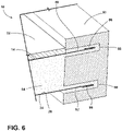
- the central plate 34 includes attachment plates 104 that can be either coupled to or integrally formed with the perimeter frame 32. As illustrated in FIGS.
- the attachment plates 104 span each of the peripheral and perimeter flanges 80, 82 of the insulated structure 10 to couple to the perimeter frame 32 as the perimeter frame 32 is set back from, at least, the peripheral flange 80.
- the attachment plates 104 and the perimeter frame 32 reinforce the side portions 76 of the insulated structure 10, as described further below.
- the central plate 34 centrally braces the reinforcement assembly 30 to reinforce the insulated structure 10 at least during the evacuation of the insulation cavity 54. Stated differently, the central plate 34 may provide additional support for the liner 22 in addition to the trim breaker 50 during the evacuation process of the insulated structure 10.
- the perimeter frame 32 of the reinforcement assembly 30 includes a top plate 106, first and second side plates 108, and a bottom plate 110.
- the central plate 34 is operably coupled to the side plates 108 via the attachment plates 104 to form the reinforcement assembly 30 along with the perimeter frame 32.
- the top plate 106, side plates 108, and the bottom plate 110 of the perimeter frame 32 are all integrally formed to define a single, unitary construction.
- the reinforcement assembly 30 may similarly be defined as a monolithic body that includes the perimeter frame 32 and the central plate 34.
- the unitary configuration of the reinforcement assembly 30 provides added structural strength to the overall insulated structure 10.
- the reinforcement assembly 30 is configured to evenly distribute a load L ( FIG. 1 ) of each of the first and second doors 36a, 36b, ( FIG. 1 ) as described in further detail below.
- the first and second doors 36a, 36b of the appliance 12 are operably coupled to the insulated structure 10 via the reinforcement assembly 30.
- the first and second doors 36a, 36b are operably coupled to the insulated structure 10 via a plurality of hinges 120.
- the plurality of hinges 120 are operably coupled to the reinforcement assembly 30, as described further below.
- the plurality of hinges 120 include a first pair of hinges 122 and a second pair of hinges 124. It is generally contemplated that the first pair of hinges 122 are configured to support the first door 36a proximate to the first compartment 62, and the second pair of hinges 124 are configured to support the second door 36b proximate to the second compartment 64.
- Both of the first and second pairs of hinges 122, 124 include the first hinge 40 and the second hinge 42, mentioned above.
- the first hinges 40 are configured to operably couple to the perimeter frame 32 of the reinforcement assembly 30.
- the second hinges 42 of the first pair of hinges 122 and the second pair of hinges 124 are illustrated as being operably coupled to the central plate 34 of the reinforcement assembly 30. Additionally or alternatively, the position of each of the first and second hinges 40, 42 may be interchanged, such that the first hinges 40 may be disposed on the central plate 34 and the second hinges 42 may be disposed on the perimeter frame 32.
- first hinges 40 coupled to the top and bottom plates 106, 110 of the perimeter frame 32, respectively.
- first hinges 40 are generally disposed on the top portion 74 and the bottom portion 78 of the insulated structure 10 by coupling to the top and bottom plates 106, 110 of the perimeter frame 32, respectively.
- the second hinges 42 can be operably coupled to the central plate 34 of the reinforcement assembly 30 proximate to each of the first and second compartments 62, 64.
- the first and second doors 36a, 36b are each operably coupled to the first and second hinges 40, 42.
- the first and second doors 36a, 36b are configured to hingedly rotate relative to the insulated structure 10 to provide selective access to each of the first and second compartments 62, 64 via the first and second hinges 40, 42.
- the first and second doors 36a, 36b define the load L that is applied to the insulated structure 10.
- the reinforcement assembly 30 is configured to offset the load L defined by the first and second doors 36a, 36b.
- the perimeter frame 32 and the central plate 34 cooperate to redistribute the load L along the reinforcement assembly 30 to alleviate the load L placed upon the insulated structure 10.
- the side plates 108 of the perimeter frame 32 advantageously absorb at least a portion of the load L applied on the top and bottom plates 106, 110 of the perimeter frame 32.
- the side plates 108 cooperate with the top and bottom plates 106, 110 to redistribute and absorb at least a portion of the load L distributed along the central plate 34.
- the load L of the doors 36a, 36b may vary, such that the load L may, for example, increase as a user adds items to support bins 130 disposed on the body 38 of each of the doors 36a, 36b.
- the body 38 of the doors 36a, 36b typically applies a force F to each of the first and second hinges 40, 42 that is generally relative to the load L of the respective door 36a, 36b.
- the first and second hinges 40, 42 can transfer the force F applied by the doors 36a, 36b to the reinforcement assembly 30, which ultimately extends the useful life of the insulated structure 10.
- the reinforcement assembly 30, rather than the insulated structure 10, absorbs the force F from the load L of the doors 36a, 36b.
- the insulated structure 10 may still accommodate a portion of the load L of the doors 36a, 36b, but the reinforcement assembly 30 provides advantageous support and redistribution of the load such that load L placed upon the insulated structure 10 is minimized.
- the even distribution of the load L of the doors 36a, 36b by the reinforcement assembly is configured to minimize potential misalignment of the doors 36a, 36b over time due to the force F acting upon the doors 36a, 36b in, at least, an open position 132 of the doors 36a, 36b.
- the first and second hinges 40, 42 are configured to engage the top plate 106, the bottom plate 110, and the central plate 34 with the load L of the doors 36a, 36b.
- the load L can then be distributed along the side plates 108 of the perimeter frame 32 to maintain the overall balance of the doors 36a, 36b relative to the appliance 12.
- the side plates 108 redistribute the load L from the top plate 106, the bottom plate 110, and the central plate 34 along the reinforcement assembly 30, such that the alignment of the doors 36a, 36b can be maintained over time to increase the overall useful life of the appliance 12 and the insulated structure 10.
- the side plates 108 reinforce the wrapper 14 to balance the load L along the side portions 76 of the insulated structure 10. Stated differently, the side plates 108 minimize the overall load L applied to the insulated structure 10. In addition, the positioning of the perimeter frame 32 along the peripheral edge 20 of the wrapper 14 reinforces the structural integrity of the wrapper 14 due to the rigid configuration of the perimeter frame 32. It is generally contemplated that the reinforcement assembly 30 can be formed from a metallic material or other structurally rigid material generally known in the art.
- the rigidity of the perimeter frame 32 maintains the planar configuration of the peripheral flange 80 of the wrapper 14.
- the positioning of the perimeter frame 32 inward along the peripheral edge 20 of the wrapper 14 further supports the wrapper 14 by bracing a more central portion of the wrapper 14 as compared to the peripheral flange 80 that is defined by the perimeter frame 32.
- the perimeter frame 32 is advantageously positioned proximate to the peripheral edge 20 of the wrapper 14, while being positioned deep enough along the top portion 74, the side portions 76, and the bottom portion 78 ( FIG. 2 ) of the wrapper 14 to reinforce the insulated structure 10.
- the reinforcement assembly 30 maintains the overall alignment of the doors 36a, 36b relative to the appliance 12 and provides structural support for the insulated structure 10.
- the side plates 108 assist in balancing the load L of the doors 36a, 36b along with the top plate 106 and the bottom plate 110.
- the central plate 34 being coupled to and/or integrally formed with the perimeter frame 32 reinforces the insulated structure 10.
- the structural reinforcement of the entire reinforcement assembly 30 cooperates with the trim breaker 50 to maintain the planar configuration of, at least, the peripheral flange 80, which extends the overall useful life of the insulated structure 10 as there is minimized bending or other alteration of the peripheral edge 20 of the wrapper 14 under vacuum pressure.
- an insulated structure for an appliance includes a wrapper that has an outer surface, an inner surface, and a peripheral edge defined by each of the outer and inner surfaces.
- a liner has an interior surface and an exterior surface. The liner is operable coupled to the wrapper.
- a mullion is operably coupled to the liner.
- a reinforcement assembly is coupled to the wrapper. The reinforcement assembly includes a perimeter frame that is disposed on the peripheral edge of the wrapper, and a central plate that is operably coupled to the mullion.
- At least one door includes a body, a first hinge that is operably coupled to the perimeter frame, and a second hinge that is operably coupled to the central plate.
- a reinforcement assembly is configured to evenly distribute a load of at least one door.
- a perimeter frame and a central plate are configured to minimize misalignment of at least one door over time.
- an outer surface of a wrapper includes a top portion, side portions, and a bottom portion.
- a perimeter frame is operably coupled to at least the top portion and the bottom portion of the outer surface.
- a central plate is operably coupled to side portions of an outer surface of a wrapper.
- At least one door includes a first door and a second door.
- the first door is coupled to a perimeter frame at a top portion of a wrapper
- the second door is coupled to the perimeter frame at a bottom portion of the wrapper.
- an insulated structure further includes a trim breaker that is operably coupled to a wrapper and a liner.
- the trim breaker is disposed along a peripheral edge of the wrapper and is proximate to a perimeter frame.
- a vacuum insulated structure for an appliance includes a wrapper that has a peripheral edge, a liner that is operably coupled to the wrapper, and a mullion operably coupled to the liner.
- the reinforcement assembly includes a perimeter frame that is operably coupled to the wrapper.
- the perimeter frame includes a top plate, side plates, and a bottom plate.
- the reinforcement assembly further includes a central plate that is operably coupled to the mullion.
- a central plate is integrally formed with side plates of a perimeter frame.
- a vacuum insulated structure further includes a door that is operably coupled to a reinforcement assembly.
- a door includes a first hinge and a second hinge.
- the first hinge is operably coupled to a perimeter frame and a second hinge is operably coupled to a central plate.
- side plates are configured to reinforce a wrapper.
- a perimeter frame is coupled to a peripheral edge of a wrapper to define a peripheral flange of a wrapper.
- a perimeter frame is constructed from a rigid material to maintain a planar configuration of a peripheral flange of a wrapper.
- an appliance includes a vacuum insulated structure that has a peripheral edge and includes a wrapper and a liner.
- a mullion is operably coupled to the vacuum insulated structure.
- a reinforcement assembly is operably coupled to the vacuum insulated structure and the mullion.
- the reinforcement assembly includes a perimeter frame that is operably coupled to the peripheral edge of the vacuum insulated structure, and a central plate that is operably coupled to the mullion.
- a door is operably coupled to the reinforcement assembly.
- a perimeter frame includes a top plate, side plates, and a bottom plate.
- the side plates are configured to reinforce a vacuum insulated structure.
- a door defines a load that is relative to a vacuum insulated structure.
- Side plates of a perimeter frame minimize the load that is applied to the vacuum insulated structure.
- a door includes a first hinge and a second hinge.
- the first hinge is operably coupled to a perimeter frame and a second hinge is operably coupled to a central plate.
- a central plate is integrally formed with a perimeter frame.
- a perimeter frame is operably coupled to a vacuum insulated structure to define a peripheral flange.
- the peripheral flange is planar under vacuum pressure.
Landscapes
- Engineering & Computer Science (AREA)
- Chemical & Material Sciences (AREA)
- Combustion & Propulsion (AREA)
- Physics & Mathematics (AREA)
- Mechanical Engineering (AREA)
- Thermal Sciences (AREA)
- General Engineering & Computer Science (AREA)
- Refrigerator Housings (AREA)
Applications Claiming Priority (1)
| Application Number | Priority Date | Filing Date | Title |
|---|---|---|---|
| US17/138,149 US11486627B2 (en) | 2020-12-30 | 2020-12-30 | Reinforcement assembly for an insulated structure |
Publications (1)
| Publication Number | Publication Date |
|---|---|
| EP4023979A1 true EP4023979A1 (de) | 2022-07-06 |
Family
ID=79019040
Family Applications (1)
| Application Number | Title | Priority Date | Filing Date |
|---|---|---|---|
| EP21216701.9A Pending EP4023979A1 (de) | 2020-12-30 | 2021-12-21 | Verstärkungsanordnung für eine isolierte struktur |
Country Status (3)
| Country | Link |
|---|---|
| US (3) | US11486627B2 (de) |
| EP (1) | EP4023979A1 (de) |
| CN (1) | CN114688819A (de) |
Cited By (1)
| Publication number | Priority date | Publication date | Assignee | Title |
|---|---|---|---|---|
| EP4345404A1 (de) * | 2022-09-27 | 2024-04-03 | Liebherr-Hausgeräte Lienz GmbH | Kühl- und/oder gefriergerät |
Families Citing this family (4)
| Publication number | Priority date | Publication date | Assignee | Title |
|---|---|---|---|---|
| DE102019213447A1 (de) * | 2019-09-04 | 2021-03-04 | BSH Hausgeräte GmbH | Kältegerätevorrichtung |
| JP2024061275A (ja) * | 2022-10-21 | 2024-05-07 | 東芝ライフスタイル株式会社 | 冷蔵庫用扉、及び冷蔵庫 |
| US12529508B2 (en) * | 2023-08-16 | 2026-01-20 | Whirlpool Corporation | Trim breaker interface for reducing air infiltration in a vacuum insulated appliance |
| US20250180278A1 (en) * | 2023-11-30 | 2025-06-05 | Whirlpool Corporation | Refrigerator with a vacuum-insulated structure supported by a structural support with a baseplate welded to the vacuum-insulated structure |
Citations (4)
| Publication number | Priority date | Publication date | Assignee | Title |
|---|---|---|---|---|
| US20040012315A1 (en) * | 2002-07-16 | 2004-01-22 | Maytag Corporation | Localized reinforcement system for refrigerator cabinet |
| US8752921B2 (en) * | 2005-11-30 | 2014-06-17 | Bsh Bosch Und Siemens Hausgerate Gmbh | Refrigerator or freezer comprising a reinforcement frame |
| US20170184341A1 (en) * | 2015-12-28 | 2017-06-29 | Whirlpool Corporation | Structural stanchion for a cabinet of an appliance |
| US20190101320A1 (en) * | 2016-05-03 | 2019-04-04 | Whirlpool Corporation | Hinge support assembly for a vacuum insulated appliance cabinet |
Family Cites Families (35)
| Publication number | Priority date | Publication date | Assignee | Title |
|---|---|---|---|---|
| US4822117A (en) * | 1987-06-12 | 1989-04-18 | General Electric Company | Refrigerator case/liner interface and related components for automated assembly |
| US5899546A (en) * | 1997-06-04 | 1999-05-04 | Maytag Corporation | Refrigerator cabinet and method of assembling the same |
| US6036293A (en) * | 1998-09-03 | 2000-03-14 | Maytag Corporation | Refrigerator cabinet and method of assembling the same |
| CA2469167C (en) * | 2003-07-11 | 2009-11-03 | Maytag Corporation | Localized reinforcement system for refrigerator cabinet |
| DE102005057143A1 (de) * | 2005-11-30 | 2007-06-06 | BSH Bosch und Siemens Hausgeräte GmbH | Kältegerät mit Isolationsleiste zum thermischen Entkoppeln der Seitenwände |
| KR100744773B1 (ko) | 2005-12-27 | 2007-08-01 | 삼성전자주식회사 | 냉장고 및 그 조립방법 |
| CN102116554A (zh) | 2010-01-04 | 2011-07-06 | Lg电子株式会社 | 电冰箱 |
| US8491070B2 (en) | 2010-10-04 | 2013-07-23 | General Electric Company | Refrigerator door pocket hinge assembly |
| JP5689387B2 (ja) | 2011-08-30 | 2015-03-25 | 日立アプライアンス株式会社 | 冷蔵庫及びその製造方法 |
| JP5812833B2 (ja) | 2011-12-06 | 2015-11-17 | 株式会社東芝 | 冷蔵庫 |
| JP5872270B2 (ja) | 2011-12-06 | 2016-03-01 | 株式会社東芝 | 冷蔵庫 |
| JP5978520B2 (ja) * | 2011-12-06 | 2016-08-24 | 東芝ライフスタイル株式会社 | 断熱箱 |
| JP6038446B2 (ja) | 2011-12-07 | 2016-12-07 | 東芝ライフスタイル株式会社 | 断熱キャビネット |
| US9140481B2 (en) * | 2012-04-02 | 2015-09-22 | Whirlpool Corporation | Folded vacuum insulated structure |
| US10017971B2 (en) | 2013-10-22 | 2018-07-10 | Whirlpool Corporation | Method of making an appliance cabinet |
| US9574819B2 (en) | 2014-01-07 | 2017-02-21 | Samsung Electronics Co., Ltd. | Refrigerator |
| WO2015105333A1 (ko) * | 2014-01-07 | 2015-07-16 | 삼성전자주식회사 | 냉장고 |
| EP2891858B1 (de) * | 2014-01-07 | 2018-04-04 | Samsung Electronics Co., Ltd | Kühlschrank |
| JP2017040432A (ja) | 2015-08-20 | 2017-02-23 | パナソニックIpマネジメント株式会社 | 冷蔵庫 |
| WO2017068776A1 (ja) | 2015-10-21 | 2017-04-27 | パナソニックIpマネジメント株式会社 | 冷蔵庫 |
| KR101810760B1 (ko) | 2016-01-05 | 2017-12-19 | 엘지전자 주식회사 | 냉장고 및 냉장고의 제어 방법 |
| KR101862564B1 (ko) | 2016-01-05 | 2018-05-30 | 엘지전자 주식회사 | 냉장고 |
| WO2017180126A1 (en) * | 2016-04-14 | 2017-10-19 | Whirlpool Corporation | Double cabinet vacuum insulated refrigerator with a structural foamed mullion |
| US9879900B1 (en) * | 2016-09-06 | 2018-01-30 | Whirlpool Corporation | Column cabinet construction and method for door construction |
| EP3526531A4 (de) * | 2016-10-11 | 2020-06-17 | Whirlpool Corporation | Strukturschrank für ein gerät mit einheitlichen metallischen kästen |
| WO2018101954A1 (en) * | 2016-12-02 | 2018-06-07 | Whirlpool Corporation | Hinge support assembly |
| EP3548816A4 (de) * | 2016-12-02 | 2020-07-01 | Whirlpool Corporation | Scharnierhalteanordnung |
| DE102016224385A1 (de) * | 2016-12-07 | 2018-06-07 | BSH Hausgeräte GmbH | Haushaltskältegerät mit einem Türanschlagholm mit einer daran mit einem wärmeleitenden Übertragungsmedium thermisch gekoppelten Heizungsleitung |
| US10234194B2 (en) * | 2017-03-16 | 2019-03-19 | Sub-Zero, Inc. | Door manufacturing method for a freezer drawer |
| KR102511095B1 (ko) * | 2017-12-13 | 2023-03-16 | 엘지전자 주식회사 | 진공단열체 및 냉장고 |
| KR102530909B1 (ko) | 2017-12-13 | 2023-05-11 | 엘지전자 주식회사 | 진공단열체 및 냉장고 |
| EP3796812B1 (de) * | 2018-05-23 | 2024-05-01 | Whirlpool Corporation | Gerätescharnieranordnung |
| US10697699B2 (en) | 2018-11-05 | 2020-06-30 | Whirlpool Corporation | Cabinet assembly of an appliance |
| KR20200072257A (ko) | 2018-12-12 | 2020-06-22 | 엘지전자 주식회사 | 진공단열체 및 냉장고 |
| US11221175B1 (en) * | 2020-12-18 | 2022-01-11 | Sub-Zero Group, Inc. | Liner hanger |
-
2020
- 2020-12-30 US US17/138,149 patent/US11486627B2/en active Active
-
2021
- 2021-12-21 EP EP21216701.9A patent/EP4023979A1/de active Pending
- 2021-12-29 CN CN202111643040.4A patent/CN114688819A/zh active Pending
-
2022
- 2022-10-27 US US17/974,828 patent/US11828525B2/en active Active
-
2023
- 2023-11-27 US US18/519,826 patent/US12313331B2/en active Active
Patent Citations (4)
| Publication number | Priority date | Publication date | Assignee | Title |
|---|---|---|---|---|
| US20040012315A1 (en) * | 2002-07-16 | 2004-01-22 | Maytag Corporation | Localized reinforcement system for refrigerator cabinet |
| US8752921B2 (en) * | 2005-11-30 | 2014-06-17 | Bsh Bosch Und Siemens Hausgerate Gmbh | Refrigerator or freezer comprising a reinforcement frame |
| US20170184341A1 (en) * | 2015-12-28 | 2017-06-29 | Whirlpool Corporation | Structural stanchion for a cabinet of an appliance |
| US20190101320A1 (en) * | 2016-05-03 | 2019-04-04 | Whirlpool Corporation | Hinge support assembly for a vacuum insulated appliance cabinet |
Cited By (1)
| Publication number | Priority date | Publication date | Assignee | Title |
|---|---|---|---|---|
| EP4345404A1 (de) * | 2022-09-27 | 2024-04-03 | Liebherr-Hausgeräte Lienz GmbH | Kühl- und/oder gefriergerät |
Also Published As
| Publication number | Publication date |
|---|---|
| US20230052982A1 (en) | 2023-02-16 |
| US11486627B2 (en) | 2022-11-01 |
| US12313331B2 (en) | 2025-05-27 |
| US20240093931A1 (en) | 2024-03-21 |
| US20220205711A1 (en) | 2022-06-30 |
| CN114688819A (zh) | 2022-07-01 |
| US11828525B2 (en) | 2023-11-28 |
Similar Documents
| Publication | Publication Date | Title |
|---|---|---|
| EP4023979A1 (de) | Verstärkungsanordnung für eine isolierte struktur | |
| EP3851778B1 (de) | Ein geräteschrank aufweisend eine verstärkungsanordnung | |
| US3910658A (en) | Refrigeration apparatus enclosure structure | |
| EP3796812B1 (de) | Gerätescharnieranordnung | |
| US6505442B2 (en) | Thermal and reinforced refrigerator door | |
| EP3443283B1 (de) | Vakuumisolierte doppelschrankkältemaschine mit strukturellem schaumpfosten | |
| EP4067790B1 (de) | Stützanordnung für eine isolierte struktur | |
| US12264868B2 (en) | Side access panel for an appliance | |
| EP2789945B1 (de) | Wärmedämmungsschrank | |
| EP3929514B1 (de) | Kühlgeräteschrankanordnung | |
| EP4502511A1 (de) | Regalstutzehalterunganordnung für einen vakuumisolierten platte | |
| WO2016141292A1 (en) | Appliance door with vacuum insulated outer door | |
| US4033806A (en) | Method of making refrigeration apparatus enclosure structure | |
| JPS6392897A (ja) | 恒温構造体 | |
| JP2020139706A (ja) | 断熱箱体およびこれを備える冷蔵庫 | |
| JP2573098B2 (ja) | ショーケース | |
| JPH08200933A (ja) | 断熱箱体 | |
| JP2000283644A (ja) | 断熱箱体の組立構造 | |
| GB2297937A (en) | Insulated structure for the casing of a refrigeration appliance | |
| JP2003058942A (ja) | 自動販売機の断熱扉およびその製作方法 | |
| JPH11281244A (ja) | ショーケース |
Legal Events
| Date | Code | Title | Description |
|---|---|---|---|
| PUAI | Public reference made under article 153(3) epc to a published international application that has entered the european phase |
Free format text: ORIGINAL CODE: 0009012 |
|
| STAA | Information on the status of an ep patent application or granted ep patent |
Free format text: STATUS: THE APPLICATION HAS BEEN PUBLISHED |
|
| AK | Designated contracting states |
Kind code of ref document: A1 Designated state(s): AL AT BE BG CH CY CZ DE DK EE ES FI FR GB GR HR HU IE IS IT LI LT LU LV MC MK MT NL NO PL PT RO RS SE SI SK SM TR |
|
| STAA | Information on the status of an ep patent application or granted ep patent |
Free format text: STATUS: REQUEST FOR EXAMINATION WAS MADE |
|
| 17P | Request for examination filed |
Effective date: 20230104 |
|
| RBV | Designated contracting states (corrected) |
Designated state(s): AL AT BE BG CH CY CZ DE DK EE ES FI FR GB GR HR HU IE IS IT LI LT LU LV MC MK MT NL NO PL PT RO RS SE SI SK SM TR |
|
| RAP3 | Party data changed (applicant data changed or rights of an application transferred) |
Owner name: WHIRLPOOL CORPORATION |
|
| STAA | Information on the status of an ep patent application or granted ep patent |
Free format text: STATUS: EXAMINATION IS IN PROGRESS |
|
| 17Q | First examination report despatched |
Effective date: 20240513 |
|
| P01 | Opt-out of the competence of the unified patent court (upc) registered |
Free format text: CASE NUMBER: APP_49085/2024 Effective date: 20240828 |