EP4023804B1 - Method for producing fiber articles - Google Patents
Method for producing fiber articles Download PDFInfo
- Publication number
- EP4023804B1 EP4023804B1 EP20856784.2A EP20856784A EP4023804B1 EP 4023804 B1 EP4023804 B1 EP 4023804B1 EP 20856784 A EP20856784 A EP 20856784A EP 4023804 B1 EP4023804 B1 EP 4023804B1
- Authority
- EP
- European Patent Office
- Prior art keywords
- fibers
- resin particles
- contact
- fiber article
- fiber
- Prior art date
- Legal status (The legal status is an assumption and is not a legal conclusion. Google has not performed a legal analysis and makes no representation as to the accuracy of the status listed.)
- Active
Links
Images


Classifications
-
- D—TEXTILES; PAPER
- D02—YARNS; MECHANICAL FINISHING OF YARNS OR ROPES; WARPING OR BEAMING
- D02G—CRIMPING OR CURLING FIBRES, FILAMENTS, THREADS, OR YARNS; YARNS OR THREADS
- D02G1/00—Producing crimped or curled fibres, filaments, yarns, or threads, giving them latent characteristics
- D02G1/12—Producing crimped or curled fibres, filaments, yarns, or threads, giving them latent characteristics using stuffer boxes
-
- D—TEXTILES; PAPER
- D04—BRAIDING; LACE-MAKING; KNITTING; TRIMMINGS; NON-WOVEN FABRICS
- D04H—MAKING TEXTILE FABRICS, e.g. FROM FIBRES OR FILAMENTARY MATERIAL; FABRICS MADE BY SUCH PROCESSES OR APPARATUS, e.g. FELTS, NON-WOVEN FABRICS; COTTON-WOOL; WADDING ; NON-WOVEN FABRICS FROM STAPLE FIBRES, FILAMENTS OR YARNS, BONDED WITH AT LEAST ONE WEB-LIKE MATERIAL DURING THEIR CONSOLIDATION
- D04H1/00—Non-woven fabrics formed wholly or mainly of staple fibres or like relatively short fibres
- D04H1/40—Non-woven fabrics formed wholly or mainly of staple fibres or like relatively short fibres from fleeces or layers composed of fibres without existing or potential cohesive properties
- D04H1/42—Non-woven fabrics formed wholly or mainly of staple fibres or like relatively short fibres from fleeces or layers composed of fibres without existing or potential cohesive properties characterised by the use of certain kinds of fibres insofar as this use has no preponderant influence on the consolidation of the fleece
- D04H1/4382—Stretched reticular film fibres; Composite fibres; Mixed fibres; Ultrafine fibres; Fibres for artificial leather
-
- D—TEXTILES; PAPER
- D02—YARNS; MECHANICAL FINISHING OF YARNS OR ROPES; WARPING OR BEAMING
- D02G—CRIMPING OR CURLING FIBRES, FILAMENTS, THREADS, OR YARNS; YARNS OR THREADS
- D02G3/00—Yarns or threads, e.g. fancy yarns; Processes or apparatus for the production thereof, not otherwise provided for
- D02G3/22—Yarns or threads characterised by constructional features, e.g. blending, filament/fibre
- D02G3/40—Yarns in which fibres are united by adhesives; Impregnated yarns or threads
-
- D—TEXTILES; PAPER
- D04—BRAIDING; LACE-MAKING; KNITTING; TRIMMINGS; NON-WOVEN FABRICS
- D04H—MAKING TEXTILE FABRICS, e.g. FROM FIBRES OR FILAMENTARY MATERIAL; FABRICS MADE BY SUCH PROCESSES OR APPARATUS, e.g. FELTS, NON-WOVEN FABRICS; COTTON-WOOL; WADDING ; NON-WOVEN FABRICS FROM STAPLE FIBRES, FILAMENTS OR YARNS, BONDED WITH AT LEAST ONE WEB-LIKE MATERIAL DURING THEIR CONSOLIDATION
- D04H1/00—Non-woven fabrics formed wholly or mainly of staple fibres or like relatively short fibres
- D04H1/70—Non-woven fabrics formed wholly or mainly of staple fibres or like relatively short fibres characterised by the method of forming fleeces or layers, e.g. reorientation of fibres
- D04H1/72—Non-woven fabrics formed wholly or mainly of staple fibres or like relatively short fibres characterised by the method of forming fleeces or layers, e.g. reorientation of fibres the fibres being randomly arranged
-
- D—TEXTILES; PAPER
- D04—BRAIDING; LACE-MAKING; KNITTING; TRIMMINGS; NON-WOVEN FABRICS
- D04H—MAKING TEXTILE FABRICS, e.g. FROM FIBRES OR FILAMENTARY MATERIAL; FABRICS MADE BY SUCH PROCESSES OR APPARATUS, e.g. FELTS, NON-WOVEN FABRICS; COTTON-WOOL; WADDING ; NON-WOVEN FABRICS FROM STAPLE FIBRES, FILAMENTS OR YARNS, BONDED WITH AT LEAST ONE WEB-LIKE MATERIAL DURING THEIR CONSOLIDATION
- D04H5/00—Non woven fabrics formed of mixtures of relatively short fibres and yarns or like filamentary material of substantial length
- D04H5/08—Non woven fabrics formed of mixtures of relatively short fibres and yarns or like filamentary material of substantial length characterised by the method of forming fleeces or layers, e.g. reorientation of fibres or yarns
-
- D—TEXTILES; PAPER
- D04—BRAIDING; LACE-MAKING; KNITTING; TRIMMINGS; NON-WOVEN FABRICS
- D04H—MAKING TEXTILE FABRICS, e.g. FROM FIBRES OR FILAMENTARY MATERIAL; FABRICS MADE BY SUCH PROCESSES OR APPARATUS, e.g. FELTS, NON-WOVEN FABRICS; COTTON-WOOL; WADDING ; NON-WOVEN FABRICS FROM STAPLE FIBRES, FILAMENTS OR YARNS, BONDED WITH AT LEAST ONE WEB-LIKE MATERIAL DURING THEIR CONSOLIDATION
- D04H1/00—Non-woven fabrics formed wholly or mainly of staple fibres or like relatively short fibres
- D04H1/40—Non-woven fabrics formed wholly or mainly of staple fibres or like relatively short fibres from fleeces or layers composed of fibres without existing or potential cohesive properties
- D04H1/42—Non-woven fabrics formed wholly or mainly of staple fibres or like relatively short fibres from fleeces or layers composed of fibres without existing or potential cohesive properties characterised by the use of certain kinds of fibres insofar as this use has no preponderant influence on the consolidation of the fleece
- D04H1/4282—Addition polymers
- D04H1/4318—Fluorine series
-
- D—TEXTILES; PAPER
- D04—BRAIDING; LACE-MAKING; KNITTING; TRIMMINGS; NON-WOVEN FABRICS
- D04H—MAKING TEXTILE FABRICS, e.g. FROM FIBRES OR FILAMENTARY MATERIAL; FABRICS MADE BY SUCH PROCESSES OR APPARATUS, e.g. FELTS, NON-WOVEN FABRICS; COTTON-WOOL; WADDING ; NON-WOVEN FABRICS FROM STAPLE FIBRES, FILAMENTS OR YARNS, BONDED WITH AT LEAST ONE WEB-LIKE MATERIAL DURING THEIR CONSOLIDATION
- D04H1/00—Non-woven fabrics formed wholly or mainly of staple fibres or like relatively short fibres
- D04H1/40—Non-woven fabrics formed wholly or mainly of staple fibres or like relatively short fibres from fleeces or layers composed of fibres without existing or potential cohesive properties
- D04H1/42—Non-woven fabrics formed wholly or mainly of staple fibres or like relatively short fibres from fleeces or layers composed of fibres without existing or potential cohesive properties characterised by the use of certain kinds of fibres insofar as this use has no preponderant influence on the consolidation of the fleece
- D04H1/4382—Stretched reticular film fibres; Composite fibres; Mixed fibres; Ultrafine fibres; Fibres for artificial leather
- D04H1/43838—Ultrafine fibres, e.g. microfibres
Definitions
- the present disclosure relates to a production method for a fiber article.
- Patent Document 1 discloses a nonwoven fabric that is a fiber article including different types of fibers.
- the present document discloses a production method for producing a nonwoven fabric by inserting a fiber stream of one type of fiber into the other fiber stream of another type of fiber while separately spinning and transferring the respective types of fibers.
- Patent Document 1 JP H06-116854 A
- a fiber article including different types of fibers for example, fibers having different outer diameters are combined and the fiber article is configured to be bulky. Consequently, the function of each of type of fiber can be achieved and the performance of the fiber article can be improved. However, it may be difficult to efficiently produce such a fiber article that has high functionality. This problem is particularly prominent in a case where fibers having an extremely small outer diameters are used.
- an object of the present disclosure is to allow for, in the case of producing a fiber article by combining different types of fibers having different outer diameters, efficiently producing a bulky fiber article having high functionality.
- a production method for a fiber article includes: a contact step of, while transferring a plurality of first fibers, bringing a plurality of resin particles formed of polytetrafluoroethylene (PTFE) that can be fiberized into contact with the plurality of first fibers; a first processing step of applying an external force to the plurality of first fibers brought into contact with the plurality of resin particles and narrowing gaps between fibers; and a second processing step of, by relieving the external force applied to the plurality of first fibers brought into contact with the plurality of resin particles, forming second fibers from the plurality of resin particles, the second fibers each having an outer diameter that is smaller than each of the first fibers and is set to a value in a range of 30 nm or greater to 1.0 ⁇ m or less, and forming a fiber composite including the first fibers and the second fibers.
- PTFE polytetrafluoroethylene
- a bulky fiber article can be produced that includes the fine second fibers each having an outer diameter set to a value in the range of 30 nm or greater to 1.0 ⁇ m or less, and the first fibers each having an outer diameter larger than that of the second fiber. Further, the fine second fibers are combined with the first fibers, and the second fibers are supported by the first fibers. Therefore, compared to a case where a fiber article is produced only from resin fibers, for example, a bulky fiber article can be produced. In addition, a fiber article that can achieve the function of the second fibers over a long period of time can be produced. Furthermore, for example, the second fibers are formed of the plurality of resin particles dispersedly brought into contact with the first fibers, and thus the second fibers can be uniformly distributed and disposed within the fiber article and a fiber article having uniform quality can be produced.
- the fiber article can be efficiently and sequentially produced with the use of a single transfer facility. Therefore, a separate step of forming the second fibers can be omitted, and production steps are simplified and thus production costs can be reduced. As a result, a bulky fiber article having high functionality can be efficiently produced.
- a band may be formed by applying the external force to the first fibers to which the plurality of resin particles is added and crimping the first fibers. Consequently, the fiber article including the first fibers and the second fibers can be efficiently produced while using the band.
- tensile force may be applied as the external force in a transfer direction to the plurality of first fibers brought into contact with the plurality of resin particles in the band.
- the plurality of first fibers may be inserted between a pair of nip rolls and pressed by the pair of nip rolls, whereby the external force is applied to the first fibers brought into contact with the plurality of resin particles.
- the external force can be efficiently applied to the first fibers.
- a dispersion in which the plurality of resin particles are dispersed may be used.
- fluidity of the dispersion can be used to easily bring the plurality of resin particles into contact with a wide range of the surface of the first fibers.
- the method may further include a drying step of, between the contact step and the first processing step, drying at least a portion of the dispersion applied to the first fibers. Therefore, by drying a portion of the dispersion before forming the band, the amount of the resin particles that drop from the first fibers can be reduced, and the weight ratio between the first fibers and the second fibers can be easily adjusted. Additionally, the resin particles are appropriately brought into contact with the first fibers, and thus formation of the second fibers in the second processing step can be facilitated.
- An aqueous dispersion obtained by dispersing the plurality of resin particles in water may be used as the dispersion.
- the dispersion can be produced at relatively low cost and the dispersion can be easily handled.
- the dispersion separated from the first fibers in the first processing step may be reused. Therefore, a reduction in the production costs can be further facilitated.
- the plurality of resin particles in a powder form may be directly brought into contact with the first fibers.
- the plurality of resin particles can be brought into contact with the first fibers in a relatively simple manner.
- nip pressure set to a value of 0.05 MPa or greater may be applied as the external force to the plurality of first fibers brought into contact with the plurality of resin particles.
- the plurality of resin particles including lamellar structures may be used. Therefore, in the second processing step, the second fibers can be easily formed from the plurality of resin particles.
- the fiber composite may be formed in which a weight ratio W1/W2 of a total weight W1 of the first fibers to a total weight W2 of the second fibers and the residual resin particles is set to a value in a range of 3.00 or greater to 200.00 or less.
- a length dimension of the first fibers may form the fiber composite that is longer than a length dimension of the second fibers.
- the first fibers are used as the framework of the fiber article and the second fibers are supported on the first fibers, and thus the function of the second fibers can be stably achieved.
- the first fibers each having an outer diameter set to a value in a range of 5 ⁇ m or greater and 50 ⁇ m or less may be used. As a result, design flexibility of the fiber article can be improved.
- the first fibers formed of at least one of rayon, polypropylene, polyethylene terephthalate, polyethylene, or cellulose acetate may be used. Additionally, in the contact step, the resin particles formed of polytetrafluoroethylene are used.
- the fiber article including the first fibers and the second fibers can be efficiently produced, and the first fibers and the second fibers respectively formed of specific materials are combined, and thus the functions of the first fibers and the second fibers can be easily achieved.
- a bulky fiber article having high functionality can be efficiently produced.
- a production method for a fiber article includes: a contact step of, while transferring a plurality of first fibers, bringing a plurality of resin particles formed of PTFE that can be fiberized into contact with the plurality of first fibers; a first processing step of applying an external force to the plurality of first fibers brought into contact with the plurality of resin particles and narrowing gaps between fibers; and a second processing step of, by relieving the external force applied to the plurality of first fibers brought into contact with the plurality of resin particles, forming second fibers from the plurality of resin particles, the second fibers each having an outer diameter that is smaller than each of the first fibers and is set to a value in a range of 30 nm or greater to 1.0 ⁇ m or less, and forming a fiber composite including the first fibers and the second fibers.
- the plurality of first fibers are crimped, and thus external force is applied to the plurality of first fibers.
- a band production apparatus and a fiber article production apparatus that are used in the production method will be described below.
- FIG. 1 is an overall view of a band production apparatus 1 according to the first embodiment.
- the band production apparatus 1 illustrated in FIG. 1 spins filaments 61 as first fibers by dry spinning. Further, the band production apparatus 1 produces a yarn 62, an end 63, and a band 64 from a plurality of the filaments 61.
- the raw material of the filament 61 may be any material from which the yarn 62, the end 63, and the band 64 are appropriately obtained, for example, in the spinning method to be selected.
- the filament 61 of the present embodiment includes at least one of rayon, polypropylene, polyethylene terephthalate, polyethylene, or cellulose acetate. As an example, the filament 61 is made of cellulose acetate.
- the band production apparatus 1 is provided with a mixing apparatus 2, a filtration apparatus 3, a spinning unit 4, lubrication units 5, godet rolls 6, guide pins 7, an application apparatus 8, a first drying apparatus 9, a crimping apparatus 10, and a second drying apparatus 11.
- a predetermined spinning dope 60 is used.
- the spinning dope 60 is formed by dissolving flakes made of, for example, cellulose diacetate in an organic solvent at a predetermined concentration.
- the spinning dope 60 is mixed by the mixing apparatus 2 and then filtered by the filtration apparatus 3.
- the spinning dope 60 passed through the filtration apparatus 3 is extruded from a plurality of orifices 15a of a spinneret 15 provided on a cabinet 14 of the spinning unit 4.
- the orifice 15a has a circumference shape formed into a predetermined shape (for example, a circular shape).
- the diameter of each orifice 15a is set as appropriate in accordance with a denier per filament (FD) of the produced filaments 61.
- the spinning dope 60 extruded from each orifice 15a is heated by hot air supplied from a drying unit (not illustrated) into the cabinet 14 and the organic solvent evaporates, and thus the spinning dope 60 is dried. As a result, the solid filaments 61 are formed.
- the plurality of filaments 61 passed through the single cabinet 14 are gathered by the guide pins 7, thereby forming the yarn 62.
- the yarn 62 is wound by the godet roll 6.
- the yarn 62 is then taken up by a predetermined winding device.
- the series of units for producing the yarn 62 i.e., the spinning unit 4 that extrudes the spinning dope 60 from the spinneret 15 and spins the filaments 61, the drying unit, the lubrication unit 5, and the winding unit that includes the godet rolls 6, is collectively referred to as a station.
- a station Typically, a plurality of stations are arranged in a line.
- a plurality of yarns 62 passed through each station is transferred along the arrangement direction of the stations and sequentially accumulated or layered.
- the plurality of yarns 62 are layered to form the end (a tow) 63, which is a flat assembly of the yarns 62.
- the end 63 is formed by layering the plurality of yarns 62 and setting the yarns to a predetermined total denier (TD).
- TD total denier
- the method for spinning the filaments 61 is not limited, and may be a method other than the dry spinning method (for example, a melt spinning method or a wet spinning method).
- the method for spinning the filaments 61 may be any method provided that the band 64 is appropriately obtained.
- the application apparatus 8 applies a dispersion including resin particles 66 to the filaments 61 while transferring a plurality of first fibers (here, the end 63).
- the application apparatus 8 includes a reservoir that stores the dispersion, and an affixing roll that is pivotally supported such that the dispersion in the reservoir is applied to the roll surface to be applied to the filaments 61.
- the dispersion of the present embodiment is an aqueous dispersion obtained by dispersing the plurality of resin particles 66 in water.
- the dispersion may include a liquid other than water.
- the resin particle 66 internally includes a lamellar structure.
- the lamellar structure herein corresponds to a structure in which polymer chains constituting a resin of the resin particles 66 are linked and folded.
- the lamellar structure internally included in the resin particles 66 comprises fine fibers, specifically, in which millions of the polymer chains are linked and formed into a ribbon shape. The fine fibers are folded and stored in the resin particles 66.
- the resin particles 66 are primary particles, and the plurality of resin particles 66 bond to each other to form secondary particles.
- the secondary particles in other words, two bonded resin particles 66
- the fine fibers are drawn out of the resin particles 66, and resin fibers 66a are formed from the resin particles 66.
- the primary particles formed of the plurality of resin particles 66 are contained in a dispersed manner in the solvent.
- the application apparatus 8 applies the dispersion to the filaments 61, and thus the plurality of resin particles 66 are dispersedly brought into contact with the surface of the filaments 61.
- the external force is applied to the plurality of filaments 61 to narrow gaps between fibers, and thus the plurality of resin particles 66 brought into contact with the surface of the different filaments 61 adhere to each other.
- the external force applied to the plurality of filaments 61 is relieved, and thus the adhered resin particles 66 are separated and the resin fibers 66a are formed.
- the resin particles 66 of the present embodiment may be formed, for example, by a polymerization reaction and may contain lamellar structures.
- the resin particles 66 are made of PTFE (polytetrafluoroethylene).
- the resin particles 66 are set to have a mean particle size of a value in a range of 100 nm or greater to 100 ⁇ m or less (for example, approximately 300 nm).
- the value of the mean particle size is further preferably in a range of 200 nm or greater to 700 nm or less, and is still further preferably in a range of 250 nm or greater to 400 nm or less.
- the mean particle size refers to the median diameter (cumulative 50% diameter (D50)) calculated from measurement results of dynamic light scattering.
- the resin particles 66 are formed, for example, by paste extrusion.
- the first drying apparatus 9 dries at least a portion of the dispersion applied to the filaments 61.
- the crimping apparatus 10 crimps the filaments 61.
- the crimping apparatus 10 includes a pair of nip rolls N1, N2 and a stuffing box 18. Rotating shafts of the pair of nip rolls N1, N2 are arranged in parallel to each other. The pair of nip rolls N1, N2 press the end 63 between the roll surfaces of the respective rolls.
- the stuffing box 18 is disposed on a rear side of the pair of nip rolls N1, N2 in a transfer direction P.
- the stuffing box 18 includes a pair of plate members C1, C2 each having a plate surface extending in the transfer direction P, and a biasing member 12.
- the pair of plate members C1, C2 are disposed with the plate surfaces facing each other across a gap G and with the gap G decreasing from a front side to a rear side of the stuffing box 18 in the transfer direction P.
- the end 63 (the plurality of filaments 61) passed through the pair of nip rolls N1, N2 is transferred in the gap G.
- the biasing member 12 is a plate member as an example, and extends in a direction perpendicular to the transfer direction P along the plate surface of the plate member C 1. A front end of the biasing member 12 in the transfer direction P is supported by the plate member C1 to be rotatable about an axis Q extending in the direction perpendicular to the transfer direction P along the plate surface of the plate member C1. The biasing member 12 is biased toward the plate surface of the plate member C2 and presses the end 63 transferred between the pair of plate members C1, C2.
- the end 63 is pressed between the pair of nip rolls N1, N2 by the pair of nip rolls N1, N2 and is thereafter pushed into the stuffing box 18.
- the end 63 is pressed against the plate surface of the plate member C2 by the biasing member 12 while being transferred in a meandering manner between the plate surfaces of the plate members C1, C2.
- the end 63 is pushed into the stuffing box 18 by the pair of nip rolls N1, N2 by a force larger than a force applied to the end 63 from the plate members C1, C2 and the biasing member 12, and thus crimping is applied to the end 63.
- the end 63 passes through the crimping apparatus 10, thereby forming the band 64.
- the plurality of filaments 61 in the end 63 are pressurized in the crimping apparatus 10. As a result, the gaps between fibers are narrowed and the plurality of resin particles 66 that have been brought into contact with the filaments 61 bond together. As a result, the secondary particles of the resin particles 66 are formed.
- nip pressure of the pair of nip rolls N1, N2 is desirably set to a value in a suitable pressure range in order to appropriately crimp the filaments 61 and reduce the amount of dropping of the dispersion from the filaments 61.
- the band 64 passed through the crimping apparatus 10 is further dried by the second drying apparatus 11.
- FIG. 2 is a schematic cross-sectional view of the band 64 produced by the band production apparatus 1 of FIG. 1 .
- the band 64 includes the plurality of crimped filaments 61 and the plurality of resin particles 66 dispersed into the band 64 and supported on the filaments 61.
- the surface of the filaments 61 is partially covered by the plurality of resin particles 66.
- the plurality of resin particles 66 are supported on the filaments 61 while being bonded together.
- the band 64 is formed to be bulky.
- the TD and FD of the band 64 may be set as appropriate.
- the FD of the band 64 is set to a value in a range of, for example, 1.0 or greater to 10.0 or less. From the perspective of appropriately securing the gaps between fibers while retaining appropriate strength of the filaments 61, it is desirable that the FD of the band 64 is further set to a value in a range of 2.0 or greater to 6.0 or less.
- the band 64 passed through the second drying apparatus 11 is accumulated and then pressurized and packaged in a packaging container 19, thereby forming a bale shape.
- FIG. 1 illustrates a cross-sectional structure of the packaging container 19.
- the PTFE used as the material of the resin particles 66 will be described.
- the PTFE is configured as high molecules that can be fiberized.
- Such PTFE is high molecular weight PTFE obtained from, for example, emulsion polymerization or suspension polymerization of TFE (tetrafluoroethylene).
- the high molecular weight PTFE may be at least any of modified PTFE or homo PTFE.
- the modified PTFE consists of TFE and a monomer (modified monomer) other than TFE.
- the modified PTFE is uniformly denatured by the modified monomer or is denatured at the early or end stage of a polymerization reaction, but the modified PTFE is not particularly limited.
- the modified PTFE includes a TFE unit based on TFE and a modified monomer unit based on a modified monomer.
- the modified monomer unit is a part of a molecular structure of the modified PTFE, and is a part derived from the modified monomer.
- the total monomer unit is derived from all monomers in the molecular structure of the modified PTFE.
- the modified monomer is not particularly limited.
- high molecular weight of the high molecular weight PTFE refers to a molecular weight at which the PTFE is easily fiberized at the time of producing the band 64 and at which fibrils having a long fiber length are obtained.
- the high molecular weight is a value of a standard specific gravity (SSG) in a rage of 2.130 or greater and 2.230 or less, and indicates a molecular weight at which melt flow substantially does not occur due to high viscosity.
- SSG standard specific gravity
- FIG. 3 is an overall view of a fiber article production apparatus 20 according to the first embodiment.
- FIG. 3 illustrates a cross-sectional structure of the packaging container 19.
- the fiber article production apparatus 20 includes a layering ring 21, a first filament opening unit 22, a turn baffle 23, a second filament opening unit 24, a pair of pre-tension rolls 25, a pair of first filament opening rolls 26, a pair of second filament opening rolls 27, a third filament opening unit 28, a pair of transfer rolls 29, and a winding roll 30.
- the layering ring 21 and the turn baffle 23 guide the bale-shaped band 64 fed up from within the packaging container 19 toward the first filament opening unit 22.
- the first filament opening unit 22, the second filament opening unit 24, and the third filament opening unit 28 open the band 64 in the width direction of the band 64 by using gas (for example, pressurized air).
- the pair of pre-tension rolls 25, the pair of first filament opening rolls 26, and the pair of second filament opening rolls 27 open the band 64 in the width direction and the transfer direction P in a state where the band 64 is subject to tensile force in the transfer direction P.
- the pair of pre-tension rolls 25 include a pair of rolls R1, R2 arranged with the roll surfaces facing each other.
- the pair of first filament opening rolls 26 include a pair of rolls R3, R4 arranged with the roll surfaces facing each other.
- the pair of second filament opening rolls 27 include a pair of rolls R5, R6 arranged with the roll surfaces facing each other. Grooves extending in a circumferential direction are formed on the roll surfaces of the rolls R3 to R6 and are configured to easily open the band 64.
- the pair of transfer rolls 29 include a pair of rolls R7, R8 arranged with the roll surfaces facing each other.
- the pair of transfer rolls 29 transfer the band 64 passed through the pair of second filament opening rolls 27 to the winding roll 30 side.
- the winding roll 30 winds the band 64 passed through the pair of transfer rolls 29.
- the band 64 fed up from within the packaging container 19 is inserted through the layering ring 21 and is thereafter opened in the width direction by the first filament opening unit 22. Afterward, the band 64 is guided by the turn baffle 23 toward the second filament opening unit 24.
- the band 64 is further opened in the width direction by the second filament opening unit 24 and is thereafter sequentially inserted between the rolls R1, R2, between the rolls R3, R4, and between the rolls R5, R6.
- the band 64 makes contact with the rolls R1 to R6.
- the rotating speed of the pair of rolls R5, R6 is higher than the rotating speed of the pair of rolls R3, R4. Therefore, the band 64 is opened in the transfer direction P and the width direction while being subject to tensile force in the transfer direction P by the pair of first filament opening rolls 26 and the pair of second filament opening rolls 27.
- FIG. 4 is a schematic cross-sectional view of the band 64 transferred between the pair of first filament opening rolls 26 and the pair of second filament opening rolls 27 of FIG. 3 .
- the band 64 is opened in the transfer direction P (the left-right direction on the plane of paper) and the width direction (the direction perpendicular to the plane of paper) by the pair of rolls 26, 27, and thus the tensile force acts on the filaments 61 and the resin particles 66 in the transfer direction P and the width direction.
- the plurality of filaments 61 in the band 64 are opened.
- the tensile force acts on the resin particles 66 to separate the resin particles 66 bonded to each other, and thus the fine fibers folded in the resin particles 66 are efficiently elongated and the resin fibers 66a are formed. Therefore, the band 64 is formed into a fiber composite 67 including the filaments 61 and the resin fibers 66a.
- the resin fibers 66a can be formed by opening the plurality of filaments 61 in the band 64 and using the tensile force applied to the band 64 during opening. Therefore, a dedicated process or equipment for separately forming the resin fibers 66a is not required.
- the resin fibers 66a are formed at the time of opening the band 64; however, the resin fibers 66a are formed by applying an external force to narrow the gaps between fibers with respect to the plurality of filaments 61 to which the plurality of resin particles 66 are brought into contact, and then relieving the external force.
- the dispersion is applied to the plurality of filaments 61 by the application apparatus 8 and then the external force is applied at least once. Thereafter, the external force is relieved, and the resin fibers 66a are formed.
- the resin fibers 66a can be also formed, for example, by applying nip pressure as the external force to the plurality of filaments 61 brought into contact with the plurality of resin particles 66, by at least any of the pair of nip rolls N1, N2, the pair of first filament opening rolls 26, and the pair of second filament opening rolls 27.
- nip pressure as the external force to the plurality of filaments 61 brought into contact with the plurality of resin particles 66
- at least one of the external forces described above may be used.
- the outer diameter of the resin fiber 66a can be adjusted by, for example, the tensile force applied to the band 64 at the time of opening the band 64. For example, when the tensile force is increased, the outer diameter of the resin fiber 66a can be set to be small and the length dimension of the resin fiber 66a can be set to be long. When the tensile force is decreased, the outer diameter of the resin fiber 66a can be set to be large and the length dimension of the resin fiber 66a can be set to be short.
- the outer diameter of the resin fiber 66a can be set to a value in a range of 30 nm or greater to 1.0 ⁇ m or less.
- the fiber composite 67 passed between the pair of second filament opening rolls 27 is inserted between the rolls R7, R8 of the pair of transfer rolls 29.
- the rotating speed of the pair of rolls R7, R8 is slower than the rotating speed of the pair of rolls R5, R6. Therefore, the tensile force applied to the fiber composite 67 in the transfer direction P between the pair of first filament opening rolls 26 and the pair of second filament opening rolls 27 is relieved between the pair of second filament opening rolls 27 and the pair of transfer rolls 29. Relieving this tensile force adjusts the fiber composite 67 to be bulky.
- FIG. 5 is a cross-sectional view of the fiber article 65 produced by the fiber article production apparatus 20 of FIG. 3 .
- the resin fibers 66a are supported on the filaments 61 while being intertwined with the filaments 61. Accordingly, even when the resin fiber 66a is thinner than the filament 61, the resin fibers 66a can be supported on the filaments 61 while the resin fibers 66a are prevented from being cut. Therefore, the function of the resin fibers 66a can be maintained over a long period of time.
- the resin fibers 66a are dispersedly disposed throughout the inside of the band 64. Note that a portion of the resin particles 66 may be decreased in size or may be exhausted within the fiber article 65 in accordance with forming of the resin fibers 66a.
- the fiber article 65 is formed bulkier by the plurality of filaments 61 that are opened with abundant gaps between fibers therein. Therefore, the fiber article 65 has an appropriate airy texture.
- the fiber article 65 is formed into a sheet-like article as an example.
- the fiber article 65 may be formed by overlaying and crimping a plurality of sheet-like fiber composites 67.
- the thickness dimension of the fiber article 65 can be easily designed by adjusting the number of fiber composites 67.
- the fiber article 65 may be formed with the plurality of sheet-like fiber composites 67 arranged side by side in the width direction. In this case, for example, the width dimension of the fiber article 65 can be easily designed by adjusting the number of the fiber composites 67.
- the value of the external force applied to the plurality of filaments 61 to form the resin fibers 66a can be set as appropriate, but may be a value of, for example, 0.05 MPa or greater.
- the value of the external force applied to the plurality of filaments 61 is desirably a value of, for example, 0.10 MPa or greater in order to obtain good filter performance.
- the upper limit of the external force may be a value of, for example, 1 MPa or greater (e.g., several tens of MPa or greater).
- the fiber article 65 is produced by a production method using the band production apparatus 1 and the fiber article production apparatus 20.
- the production method includes a contact step, a first processing step, and a second processing step.
- the production method of the present embodiment further includes a drying step.
- the contact step is a step of bringing the plurality of resin particles 66 formed of PTFE that can be fiberized (in the present embodiment, the dispersion that includes the plurality of resin particles 66 containing lamellar structures and connected to each other) into contact with the filaments 61 while transferring the plurality of filaments 61.
- the first processing step is a step of applying an external force to the plurality of filaments 61 brought into contact with the plurality of resin particles 66, and narrowing the gaps between fibers.
- the external force is applied to the filaments 61 to which the plurality of resin particles 66 are added and the filaments 61 are crimped, and thus the band 64 is formed. Furthermore, for example, in the first processing step, while transferring the band 64, tensile force is applied as the external force in the transfer direction P to the plurality of filaments 61 in the band 64 brought into contact with the plurality of resin particles 66.
- nip pressure set to a value of 0.05 MPa or greater is further applied as the external force to the plurality of filaments 61 brought into contact with the plurality of resin particles 66.
- the nip pressure is applied, for example, by at least any (here, by all) of the pair of nip rolls N1, N2, the pair of first filament opening rolls 26, and the pair of second filament opening rolls 27.
- the resin fibers 66a are abundantly formed.
- the second processing step is a step of forming the resin fibers 66a from the plurality of resin particles 66 by relieving the external force applied to the plurality of filaments 61 brought into contact with the resin particles 66, and forming the fiber composite 67 including the filaments 61 and the resin fibers 66a.
- the drying step is a step of, between the contact step and the first processing step, drying at least a portion of the dispersion applied to the filaments 61.
- the dispersion separated from the filaments 61 in the first processing step is recovered, and the recovered dispersion is used in the contact step.
- a weight ratio W1/W2 of a total weight W1 of the filaments 61 and a total weight W2 of the resin fibers 66a and the residual resin particles 66 can be set as appropriate.
- the fiber composite 67 in which, for example, the weight ratio W1/W2 is set to a value in a range of 3.00 or greater to 200.00 or less is formed.
- the weight ratio W1/W2 may include a value in a range of 9.00 or greater to 200 or less.
- a value in the range of the weight ratio W1/W2 corresponds to a value in a range of 0.5% or greater to 10% or less of the application concentration of PTFE in the fiber composite 67.
- the filaments 61 each having an outer diameter set to a value in a range of 5 ⁇ m or greater to 50 ⁇ m is used. As a result, design flexibility of the fiber article can be improved.
- a volume ratio V1/V2 of a total volume V1 of the filaments 61 (first fibers) to a total volume V2 of the resin fibers 66a (second fibers) and the residual resin particles 66 has a maximum value of 124.0 or less.
- the function of the resin fibers 66a can be easily achieved while the gaps between fibers inside of the fiber article 65 are appropriately maintained and the resin fibers 66a are stably held by the filaments 61.
- the length dimension of the filaments 61 and the length dimension of the resin fibers 66a can be set as appropriate.
- the length dimension of the filaments 61 forms the fiber composite 67 that is longer than the length dimension of the resin fibers 66a.
- the filaments 61 are used as the framework of the fiber article 65 and the resin fibers 66a are supported on the filaments 61, and thus the function of the resin fibers 66a can be stably achieved.
- the bulky fiber article 65 can be produced that includes the fine resin fibers 66a each having an outer diameter set to a value in the range of 30 nm or greater to 1.0 ⁇ m or less, and the filaments 61 each having an outer diameter larger than that of the resin fiber 66a. Further, the fine resin fibers 66a are combined with the filaments 61, and the resin fibers 66a are supported by the filaments 61. Therefore, compared to a case where a fiber article is produced only from resin fibers, for example, the bulky fiber article 65 can be produced and the function of the resin fibers 66a in the fiber article 65 can be achieved over a long time.
- the fiber article 65 can be efficiently and sequentially produced with the use of a single transfer facility. Therefore, a separate step of forming the resin fibers 66a can be omitted, and production steps are simplified and thus production costs can be reduced. As a result, the bulky fiber article 65 having high functionality can be efficiently produced.
- the external force is applied to the filaments 61 to which the plurality of resin particles 66 are added, thereby crimping the filaments 61. Therefore, the band 64 is formed. Consequently, the fiber article 65 including the filaments 61 and the resin fibers 66a can be efficiently produced while using the band 64.
- tensile force is applied as the external force in the transfer direction to the band 64 while transferring the band 64. Therefore, in the first processing step, the external force can be efficiently applied to the filaments 61.
- the dispersion in which the plurality of resin particles 66 are dispersed is used.
- fluidity of the dispersion can be utilized to easily bring the plurality of resin particles 66 into contact with a wide range of the surface of the filaments 61.
- the production method includes the drying step, by drying a portion of the dispersion before forming the band 64, the amount of the resin particles 66 that drop from the filaments 61 can be reduced, and the weight ratio between the filaments 61 and the resin fibers 66a can be easily adjusted. Further, the resin particles 66 are appropriately brought into contact with the filaments 61, and thus the formation of the resin fibers 66a in the second processing step can be facilitated.
- the dispersion can be produced at relatively low cost and the dispersion can be easily handled. Further, the dispersion separated from the filaments 61 in the first processing step is reused in the contact step, and therefore a reduction in the production costs can be further facilitated.
- nip pressure set to a value of 0.05 MPa or greater is applied as the external force to the plurality of filaments 61 brought into contact with the plurality of resin particles 66.
- the resin fibers 66a can be appropriately and easily formed.
- the plurality of resin particles 66 including lamellar structures are used. Therefore, in the second processing step, the resin fibers 66a can be easily formed from the plurality of resin particles 66.
- the filaments 61 formed of at least one of rayon, polypropylene, polyethylene terephthalate, polyethylene, or cellulose acetate may be used.
- the resin particles 66 formed of polytetrafluoroethylene are used.
- the fiber article 65 including the filaments 61 and the resin fibers 66a can be efficiently produced, and the filaments 61 and the resin fibers 66a respectively formed of specific materials are combined, and thus the functions of the filaments 61 and the resin fibers 66a can be easily achieved.
- the external force applied to the plurality of filaments 61 may be a force applied to the plurality of filaments 61 at a timing other than the timing of crimping the filaments 61 or opening the band including the crimped filaments 61.
- FIG. 6 is a schematic diagram of a band production apparatus 101 according to a modified example of the first embodiment.
- the band production apparatus 101 includes a particle adding apparatus (feeder) 16.
- the particle adding apparatus 16 is disposed at the cabinet 14 side rather than at the crimping apparatus 10 (here, between the godet rolls 6 and the crimping apparatus 10 in the transfer direction P) such that the resin particles 66 in a powder form can be added to the filaments 61.
- the plurality of resin particles 66 in a powder form are directly applied to the filaments 61 in the contact step of the present modified example.
- water or a fiber oil agent is usually applied to the filaments 61 to be introduced into the crimping apparatus 10. Therefore, the resin particles 66 appropriately adhere to the surface of the filaments 61.
- the plurality of resin particles 66 can be brought into contact with the filaments 61 in a relatively simple manner.
- a second embodiment will be described focusing on differences from the first embodiment.
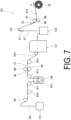
- FIG. 7 is a schematic view of a fiber article production apparatus 201 according to a second embodiment.
- a bale-like band 164 that does not include the resin particles 66 and is not crimped is used.
- the band 164 is compressed and packaged in a packaging container 119.
- the fiber article production apparatus 201 includes a plurality of guide members (for example, guide rolls R9 to R16) dispersedly disposed to guide the band 164 fed from the packaging container 119 in the transfer direction P, an application apparatus 108 that applies a dispersion to the band 164 being transferred, a pair of nip rolls N4, N5 that causes the tow band 164 to which the dispersion is applied to pass through a nip point N3, and a drying apparatus 131 that dries the band 164 (fiber composite 67) passed through the nip rolls N4, N5.
- guide members for example, guide rolls R9 to R16
- the band 164 is guided by the guide roll R12 and immersed in the dispersion based on a dip coating method, thereby being applied with the dispersion.
- the band 164 to which the dispersion is applied by the application apparatus 108 and which is dried by the drying apparatus 13 is temporarily packaged in another packaging container 120.
- the fiber article production apparatus 201 also includes the first filament opening unit 22 that widens the band 164 fed from the packaging container 120, a turn baffle 123 that guides the band 164, the second filament opening unit 24 that widens the band 164 passed through the turn baffle 123, and a pair of nip rolls N7, N8 that causes the band 164 passed through the second filament opening unit 24 to pass through a nip point N6.
- the band 164 to which the plurality of resin particles 66 are brought into contact passes through the nip point N3 of the nip rolls N4, N5, and an external force (nip pressure) is applied to the plurality of filaments 61 to narrow the gaps between fibers. Also, thereafter, the external force applied to the filaments 61 is relieved. At this time, in the gaps between fibers, a large number of the resin particles 66 are dispersed and brought into contact with the surface of the plurality of filaments 61, and the gaps between fibers are narrowed by the external force. Thereby, the resin particles 66 brought into contact with the surfaces of different filaments 61 are bonded together.
- the resin fibers 66a are formed from the resin particles 66 brought into contact with the filaments 61 of the band 164, and the fiber composite 67 is formed.
- the resin fibers 66a are also formed by passing the band 164 through the nip point N6 of the nip rolls N7, N8.
- the fiber composite 67 is wound on the predetermined winding roll 30. The wound fiber composite 67 is cut to predetermined dimensions, and thus the fiber article 65 is obtained.
- the plurality of filaments 61 are inserted between the pair of nip rolls N4, N5 and pressed by the pair of nip rolls N4, N5, thereby applying the external force to the filaments 61 to which the resin particles 66 are brought into contact.
- Such a method can also efficiently produce the fiber article 65.
- the fiber article 65 using the filaments 61 that are not crimped is obtained. Therefore, design flexibility of the fiber article 65 can be improved. Note that when the nip rolls N4, N5 and the nip rolls N7, N8 are used as in the present embodiment, for example, the nip rolls N7, N8 may be omitted.
- a confirmation test was performed to confirm the numerical range of the external force that enables the resin fibers 66a to be formed in the first processing step.
- the pressure (nip pressure) of the pair of nip rolls N1, N2 was changed in a range of 0.05 MPa or greater to 0.06 MPa or less.
- the pressure (nip pressure) of each of the pair of first filament opening rolls 26 and the pair of second filament opening rolls 27 was changed in a range of 0.10 MPa or greater to 0.41 MPa or less. Accordingly, the setting conditions of Examples 1 to 7 were prepared.
- Comparative Example 1 was prepared in which the pressure (nip pressure) of any of the pair of nip rolls N1, N2, the pair of first filament opening rolls 26, and the pair of second filament opening rolls 27 was set to 0 MPa. The results are indicated in Table 1.
- packaging the band 64 produced by the band production apparatus 1, 101 into the packaging container 19 is described.
- the fiber article 65 may be produced by introducing the band 64 into the fiber article production apparatus 20 without packaging the band 64.
- the configuration of the fiber article production apparatus 20 is not limited to that described above.
- a slurry containing a relatively large amount of the resin particles 66 may be used as the dispersion used in the contact step. Additionally, the resin particles 66 may be brought into contact with the filaments 61 prior to forming the yarn 62 or the end 63.
Landscapes
- Engineering & Computer Science (AREA)
- Textile Engineering (AREA)
- Mechanical Engineering (AREA)
- Yarns And Mechanical Finishing Of Yarns Or Ropes (AREA)
- Nonwoven Fabrics (AREA)
- Treatments For Attaching Organic Compounds To Fibrous Goods (AREA)
Applications Claiming Priority (2)
| Application Number | Priority Date | Filing Date | Title |
|---|---|---|---|
| JP2019158820 | 2019-08-30 | ||
| PCT/JP2020/032652 WO2021039979A1 (ja) | 2019-08-30 | 2020-08-28 | 繊維物品の製造方法 |
Publications (4)
| Publication Number | Publication Date |
|---|---|
| EP4023804A1 EP4023804A1 (en) | 2022-07-06 |
| EP4023804A4 EP4023804A4 (en) | 2023-09-06 |
| EP4023804C0 EP4023804C0 (en) | 2024-10-02 |
| EP4023804B1 true EP4023804B1 (en) | 2024-10-02 |
Family
ID=74685074
Family Applications (1)
| Application Number | Title | Priority Date | Filing Date |
|---|---|---|---|
| EP20856784.2A Active EP4023804B1 (en) | 2019-08-30 | 2020-08-28 | Method for producing fiber articles |
Country Status (5)
| Country | Link |
|---|---|
| US (1) | US12180627B2 (https=) |
| EP (1) | EP4023804B1 (https=) |
| JP (1) | JP7555344B2 (https=) |
| CN (1) | CN114144548B (https=) |
| WO (1) | WO2021039979A1 (https=) |
Families Citing this family (6)
| Publication number | Priority date | Publication date | Assignee | Title |
|---|---|---|---|---|
| JP7624302B2 (ja) * | 2020-09-30 | 2025-01-30 | 株式会社ダイセル | 繊維物品の製造方法 |
| WO2023095301A1 (ja) | 2021-11-26 | 2023-06-01 | 株式会社ダイセル | 乾式不織布製造方法 |
| JPWO2024228360A1 (https=) * | 2023-05-02 | 2024-11-07 | ||
| CN120981618A (zh) * | 2023-05-02 | 2025-11-18 | 株式会社大赛璐 | 纤维物品的制造方法 |
| WO2024228258A1 (ja) * | 2023-05-02 | 2024-11-07 | 株式会社ダイセル | 繊維物品の製造方法 |
| JP2026037654A (ja) * | 2024-08-22 | 2026-03-06 | 株式会社ダイセル | 繊維積層体 |
Family Cites Families (12)
| Publication number | Priority date | Publication date | Assignee | Title |
|---|---|---|---|---|
| JPH0291262A (ja) * | 1988-09-26 | 1990-03-30 | Asahi Chem Ind Co Ltd | 高強力不織布 |
| JPH06116854A (ja) | 1991-04-03 | 1994-04-26 | Toyobo Co Ltd | 特殊不織布 |
| JP4518223B2 (ja) * | 2000-03-31 | 2010-08-04 | 日本ケミコン株式会社 | 電気二重層コンデンサ用分極性電極およびその製造方法 |
| JP4863894B2 (ja) * | 2007-01-29 | 2012-01-25 | 日本バイリーン株式会社 | 不織布及びその製造方法 |
| JP5405926B2 (ja) * | 2009-07-09 | 2014-02-05 | 帝人株式会社 | 繊維構造体および繊維製品 |
| JP2012188774A (ja) * | 2011-03-09 | 2012-10-04 | Mitsubishi Paper Mills Ltd | 不織布及び不織布の製造方法 |
| US8956466B2 (en) | 2011-08-01 | 2015-02-17 | Texwipe (a division of Illinois Tool Works Inc.) | Process for preparing sorptive substrates, and integrated processing system for substrates |
| CN103987886B (zh) * | 2011-12-05 | 2016-04-27 | 日本华尔卡工业株式会社 | 包含氟树脂纤维的氟树脂类片及其制造方法 |
| CN104245827B (zh) | 2012-04-20 | 2019-09-06 | 大金工业株式会社 | 以ptfe为主要成分的组合物、混合粉末、成型用材料和过滤器用滤材、空气过滤器单元、以及多孔膜的制造方法 |
| RU2710434C2 (ru) | 2014-11-28 | 2019-12-26 | Дайсел Корпорэйшн | Целлюлозно-ацетатная волокнистая жгутовая лента для использования в сигаретном фильтре, сигаретный фильтр, устройство для изготовления жгутовой ленты и способ изготовления жгутовой ленты |
| WO2017009882A1 (ja) | 2015-07-15 | 2017-01-19 | 株式会社ダイセル | トウ開繊装置、これを用いた繊維シート製造装置、及び、繊維シートの製造方法 |
| JP6761685B2 (ja) * | 2016-07-05 | 2020-09-30 | 株式会社ダイセル | 吸収性物品製造装置及び吸収性物品の製造方法 |
-
2020
- 2020-08-28 CN CN202080053461.9A patent/CN114144548B/zh active Active
- 2020-08-28 JP JP2021543053A patent/JP7555344B2/ja active Active
- 2020-08-28 EP EP20856784.2A patent/EP4023804B1/en active Active
- 2020-08-28 US US17/637,741 patent/US12180627B2/en active Active
- 2020-08-28 WO PCT/JP2020/032652 patent/WO2021039979A1/ja not_active Ceased
Also Published As
| Publication number | Publication date |
|---|---|
| EP4023804C0 (en) | 2024-10-02 |
| US20220282413A1 (en) | 2022-09-08 |
| EP4023804A1 (en) | 2022-07-06 |
| CN114144548A (zh) | 2022-03-04 |
| CN114144548B (zh) | 2023-04-25 |
| JP7555344B2 (ja) | 2024-09-24 |
| US12180627B2 (en) | 2024-12-31 |
| JPWO2021039979A1 (https=) | 2021-03-04 |
| EP4023804A4 (en) | 2023-09-06 |
| WO2021039979A1 (ja) | 2021-03-04 |
Similar Documents
| Publication | Publication Date | Title |
|---|---|---|
| EP4023804B1 (en) | Method for producing fiber articles | |
| CN107849753B (zh) | 基于纳米纤维的复合假捻纱及其制备方法 | |
| KR20220107074A (ko) | 셀룰로오스 아세테이트 토우 밴드 및 셀룰로오스 아세테이트 토우 밴드의 제조 방법 | |
| MXPA05003033A (es) | Telas industriales no tejidas con propiedades mejoradas de barrera. | |
| EP3763862A1 (en) | Non-woven fabric and filter | |
| CN105926079A (zh) | 聚丙烯膜裂纤维及制备方法以及由其制备的空气过滤材料 | |
| RU2660071C1 (ru) | Способ получения нановолоконной нити с высокой прочностью на растяжение | |
| EP4023803B1 (en) | Fiber article | |
| TWI820405B (zh) | 纖維物品之製造方法 | |
| US12152325B2 (en) | Dry-laid nonwoven fabric production method | |
| JP6359117B2 (ja) | トウバンドの製造方法及びトウバンド製造装置 | |
| CN108842242B (zh) | 纳米纤维纱线及其制备方法 | |
| EP4707446A1 (en) | Fiber article manufacturing method | |
| CN112714808B (zh) | 共聚聚苯硫醚纤维 | |
| EP4023319A1 (en) | Air filter filtration material and air filter product | |
| WO2024228258A1 (ja) | 繊維物品の製造方法 | |
| Han et al. | The effects of electrospinning parameters on coaxial polyacrylonitrile/polyurethane nanofibers: Morphology and water vapour transmission rate | |
| WO2026042769A1 (ja) | 積層体 | |
| EP4299809A1 (en) | Nonwoven substrate comprising at least one fibrous layer | |
| EP4707445A1 (en) | Fiber article | |
| JP2026037654A (ja) | 繊維積層体 | |
| CN108866683A (zh) | 辊距钩针相对位置自动微调控制装置 | |
| KR20250045703A (ko) | Ptfe 화이버 제작용 시트 생산장비의 쿨링 시스템 | |
| Wang | Rapid, controllable and environmentally benign fabrication of thermoplastic nanofibers and applications |
Legal Events
| Date | Code | Title | Description |
|---|---|---|---|
| STAA | Information on the status of an ep patent application or granted ep patent |
Free format text: STATUS: THE INTERNATIONAL PUBLICATION HAS BEEN MADE |
|
| PUAI | Public reference made under article 153(3) epc to a published international application that has entered the european phase |
Free format text: ORIGINAL CODE: 0009012 |
|
| STAA | Information on the status of an ep patent application or granted ep patent |
Free format text: STATUS: REQUEST FOR EXAMINATION WAS MADE |
|
| 17P | Request for examination filed |
Effective date: 20220323 |
|
| AK | Designated contracting states |
Kind code of ref document: A1 Designated state(s): AL AT BE BG CH CY CZ DE DK EE ES FI FR GB GR HR HU IE IS IT LI LT LU LV MC MK MT NL NO PL PT RO RS SE SI SK SM TR |
|
| DAV | Request for validation of the european patent (deleted) | ||
| DAX | Request for extension of the european patent (deleted) | ||
| REG | Reference to a national code |
Ref country code: DE Ref legal event code: R079 Free format text: PREVIOUS MAIN CLASS: D04H0001720000 Ipc: D04H0005080000 Ref country code: DE Ref legal event code: R079 Ref document number: 602020038826 Country of ref document: DE Free format text: PREVIOUS MAIN CLASS: D04H0001720000 Ipc: D04H0005080000 |
|
| A4 | Supplementary search report drawn up and despatched |
Effective date: 20230803 |
|
| RIC1 | Information provided on ipc code assigned before grant |
Ipc: D04H 1/4318 20120101ALN20230728BHEP Ipc: D04H 1/4382 20120101ALN20230728BHEP Ipc: D04H 5/08 20120101AFI20230728BHEP |
|
| STAA | Information on the status of an ep patent application or granted ep patent |
Free format text: STATUS: EXAMINATION IS IN PROGRESS |
|
| 17Q | First examination report despatched |
Effective date: 20240311 |
|
| GRAP | Despatch of communication of intention to grant a patent |
Free format text: ORIGINAL CODE: EPIDOSNIGR1 |
|
| STAA | Information on the status of an ep patent application or granted ep patent |
Free format text: STATUS: GRANT OF PATENT IS INTENDED |
|
| RIC1 | Information provided on ipc code assigned before grant |
Ipc: D04H 1/4318 20120101ALN20240426BHEP Ipc: D04H 1/4382 20120101ALN20240426BHEP Ipc: D02G 1/12 20060101ALI20240426BHEP Ipc: D04H 5/08 20120101AFI20240426BHEP |
|
| INTG | Intention to grant announced |
Effective date: 20240522 |
|
| GRAS | Grant fee paid |
Free format text: ORIGINAL CODE: EPIDOSNIGR3 |
|
| GRAA | (expected) grant |
Free format text: ORIGINAL CODE: 0009210 |
|
| STAA | Information on the status of an ep patent application or granted ep patent |
Free format text: STATUS: THE PATENT HAS BEEN GRANTED |
|
| AK | Designated contracting states |
Kind code of ref document: B1 Designated state(s): AL AT BE BG CH CY CZ DE DK EE ES FI FR GB GR HR HU IE IS IT LI LT LU LV MC MK MT NL NO PL PT RO RS SE SI SK SM TR |
|
| REG | Reference to a national code |
Ref country code: GB Ref legal event code: FG4D |
|
| REG | Reference to a national code |
Ref country code: CH Ref legal event code: EP |
|
| REG | Reference to a national code |
Ref country code: DE Ref legal event code: R096 Ref document number: 602020038826 Country of ref document: DE |
|
| REG | Reference to a national code |
Ref country code: IE Ref legal event code: FG4D |
|
| U01 | Request for unitary effect filed |
Effective date: 20241002 |
|
| U07 | Unitary effect registered |
Designated state(s): AT BE BG DE DK EE FI FR IT LT LU LV MT NL PT RO SE SI Effective date: 20241025 |
|
| PG25 | Lapsed in a contracting state [announced via postgrant information from national office to epo] |
Ref country code: IS Free format text: LAPSE BECAUSE OF FAILURE TO SUBMIT A TRANSLATION OF THE DESCRIPTION OR TO PAY THE FEE WITHIN THE PRESCRIBED TIME-LIMIT Effective date: 20250202 Ref country code: HR Free format text: LAPSE BECAUSE OF FAILURE TO SUBMIT A TRANSLATION OF THE DESCRIPTION OR TO PAY THE FEE WITHIN THE PRESCRIBED TIME-LIMIT Effective date: 20241002 |
|
| PG25 | Lapsed in a contracting state [announced via postgrant information from national office to epo] |
Ref country code: ES Free format text: LAPSE BECAUSE OF FAILURE TO SUBMIT A TRANSLATION OF THE DESCRIPTION OR TO PAY THE FEE WITHIN THE PRESCRIBED TIME-LIMIT Effective date: 20241002 |
|
| PG25 | Lapsed in a contracting state [announced via postgrant information from national office to epo] |
Ref country code: NO Free format text: LAPSE BECAUSE OF FAILURE TO SUBMIT A TRANSLATION OF THE DESCRIPTION OR TO PAY THE FEE WITHIN THE PRESCRIBED TIME-LIMIT Effective date: 20250102 |
|
| PG25 | Lapsed in a contracting state [announced via postgrant information from national office to epo] |
Ref country code: GR Free format text: LAPSE BECAUSE OF FAILURE TO SUBMIT A TRANSLATION OF THE DESCRIPTION OR TO PAY THE FEE WITHIN THE PRESCRIBED TIME-LIMIT Effective date: 20250103 |
|
| PG25 | Lapsed in a contracting state [announced via postgrant information from national office to epo] |
Ref country code: PL Free format text: LAPSE BECAUSE OF FAILURE TO SUBMIT A TRANSLATION OF THE DESCRIPTION OR TO PAY THE FEE WITHIN THE PRESCRIBED TIME-LIMIT Effective date: 20241002 Ref country code: CZ Free format text: LAPSE BECAUSE OF FAILURE TO SUBMIT A TRANSLATION OF THE DESCRIPTION OR TO PAY THE FEE WITHIN THE PRESCRIBED TIME-LIMIT Effective date: 20241002 |
|
| PG25 | Lapsed in a contracting state [announced via postgrant information from national office to epo] |
Ref country code: RS Free format text: LAPSE BECAUSE OF FAILURE TO SUBMIT A TRANSLATION OF THE DESCRIPTION OR TO PAY THE FEE WITHIN THE PRESCRIBED TIME-LIMIT Effective date: 20250102 |
|
| PG25 | Lapsed in a contracting state [announced via postgrant information from national office to epo] |
Ref country code: SM Free format text: LAPSE BECAUSE OF FAILURE TO SUBMIT A TRANSLATION OF THE DESCRIPTION OR TO PAY THE FEE WITHIN THE PRESCRIBED TIME-LIMIT Effective date: 20241002 |
|
| PG25 | Lapsed in a contracting state [announced via postgrant information from national office to epo] |
Ref country code: SK Free format text: LAPSE BECAUSE OF FAILURE TO SUBMIT A TRANSLATION OF THE DESCRIPTION OR TO PAY THE FEE WITHIN THE PRESCRIBED TIME-LIMIT Effective date: 20241002 |
|
| PLBE | No opposition filed within time limit |
Free format text: ORIGINAL CODE: 0009261 |
|
| STAA | Information on the status of an ep patent application or granted ep patent |
Free format text: STATUS: NO OPPOSITION FILED WITHIN TIME LIMIT |
|
| 26N | No opposition filed |
Effective date: 20250703 |
|
| U20 | Renewal fee for the european patent with unitary effect paid |
Year of fee payment: 6 Effective date: 20250827 |
|
| REG | Reference to a national code |
Ref country code: CH Ref legal event code: H13 Free format text: ST27 STATUS EVENT CODE: U-0-0-H10-H13 (AS PROVIDED BY THE NATIONAL OFFICE) Effective date: 20260324 |
|
| PG25 | Lapsed in a contracting state [announced via postgrant information from national office to epo] |
Ref country code: MC Free format text: LAPSE BECAUSE OF FAILURE TO SUBMIT A TRANSLATION OF THE DESCRIPTION OR TO PAY THE FEE WITHIN THE PRESCRIBED TIME-LIMIT Effective date: 20241002 |
|
| PG25 | Lapsed in a contracting state [announced via postgrant information from national office to epo] |
Ref country code: CH Free format text: LAPSE BECAUSE OF NON-PAYMENT OF DUE FEES Effective date: 20250831 |