EP4022158B1 - Meuble, en particulier armoire - Google Patents
Meuble, en particulier armoire Download PDFInfo
- Publication number
- EP4022158B1 EP4022158B1 EP20711639.3A EP20711639A EP4022158B1 EP 4022158 B1 EP4022158 B1 EP 4022158B1 EP 20711639 A EP20711639 A EP 20711639A EP 4022158 B1 EP4022158 B1 EP 4022158B1
- Authority
- EP
- European Patent Office
- Prior art keywords
- side wall
- closure flap
- suspension frame
- furniture
- piece
- Prior art date
- Legal status (The legal status is an assumption and is not a legal conclusion. Google has not performed a legal analysis and makes no representation as to the accuracy of the status listed.)
- Active
Links
Images


Classifications
-
- E—FIXED CONSTRUCTIONS
- E06—DOORS, WINDOWS, SHUTTERS, OR ROLLER BLINDS IN GENERAL; LADDERS
- E06B—FIXED OR MOVABLE CLOSURES FOR OPENINGS IN BUILDINGS, VEHICLES, FENCES OR LIKE ENCLOSURES IN GENERAL, e.g. DOORS, WINDOWS, BLINDS, GATES
- E06B3/00—Window sashes, door leaves, or like elements for closing wall or like openings; Layout of fixed or moving closures, e.g. windows in wall or like openings; Features of rigidly-mounted outer frames relating to the mounting of wing frames
- E06B3/32—Arrangements of wings characterised by the manner of movement; Arrangements of movable wings in openings; Features of wings or frames relating solely to the manner of movement of the wing
- E06B3/50—Arrangements of wings characterised by the manner of movement; Arrangements of movable wings in openings; Features of wings or frames relating solely to the manner of movement of the wing with more than one kind of movement
- E06B3/5045—Arrangements of wings characterised by the manner of movement; Arrangements of movable wings in openings; Features of wings or frames relating solely to the manner of movement of the wing with more than one kind of movement specially adapted for furniture
-
- E—FIXED CONSTRUCTIONS
- E05—LOCKS; KEYS; WINDOW OR DOOR FITTINGS; SAFES
- E05D—HINGES OR SUSPENSION DEVICES FOR DOORS, WINDOWS OR WINGS
- E05D15/00—Suspension arrangements for wings
- E05D15/56—Suspension arrangements for wings with successive different movements
- E05D15/58—Suspension arrangements for wings with successive different movements with both swinging and sliding movements
- E05D15/581—Suspension arrangements for wings with successive different movements with both swinging and sliding movements the swinging axis laying in the sliding direction
-
- A—HUMAN NECESSITIES
- A47—FURNITURE; DOMESTIC ARTICLES OR APPLIANCES; COFFEE MILLS; SPICE MILLS; SUCTION CLEANERS IN GENERAL
- A47B—TABLES; DESKS; OFFICE FURNITURE; CABINETS; DRAWERS; GENERAL DETAILS OF FURNITURE
- A47B55/00—Cabinets, racks or shelf units, having essential features of rigid construction
-
- E—FIXED CONSTRUCTIONS
- E05—LOCKS; KEYS; WINDOW OR DOOR FITTINGS; SAFES
- E05B—LOCKS; ACCESSORIES THEREFOR; HANDCUFFS
- E05B65/00—Locks or fastenings for special use
- E05B65/44—Locks or fastenings for special use for furniture
-
- E—FIXED CONSTRUCTIONS
- E05—LOCKS; KEYS; WINDOW OR DOOR FITTINGS; SAFES
- E05Y—INDEXING SCHEME ASSOCIATED WITH SUBCLASSES E05D AND E05F, RELATING TO CONSTRUCTION ELEMENTS, ELECTRIC CONTROL, POWER SUPPLY, POWER SIGNAL OR TRANSMISSION, USER INTERFACES, MOUNTING OR COUPLING, DETAILS, ACCESSORIES, AUXILIARY OPERATIONS NOT OTHERWISE PROVIDED FOR, APPLICATION THEREOF
- E05Y2201/00—Constructional elements; Accessories therefor
- E05Y2201/60—Suspension or transmission members; Accessories therefor
- E05Y2201/622—Suspension or transmission members elements
- E05Y2201/684—Rails; Tracks
-
- E—FIXED CONSTRUCTIONS
- E05—LOCKS; KEYS; WINDOW OR DOOR FITTINGS; SAFES
- E05Y—INDEXING SCHEME ASSOCIATED WITH SUBCLASSES E05D AND E05F, RELATING TO CONSTRUCTION ELEMENTS, ELECTRIC CONTROL, POWER SUPPLY, POWER SIGNAL OR TRANSMISSION, USER INTERFACES, MOUNTING OR COUPLING, DETAILS, ACCESSORIES, AUXILIARY OPERATIONS NOT OTHERWISE PROVIDED FOR, APPLICATION THEREOF
- E05Y2900/00—Application of doors, windows, wings or fittings thereof
- E05Y2900/20—Application of doors, windows, wings or fittings thereof for furniture, e.g. cabinets
- E05Y2900/212—Doors disappearing in pockets in the furniture body
Definitions
- the invention relates to a piece of furniture, in particular in the form of a cupboard.
- Furniture particularly in the form of a (lockable) cupboard, is used to store objects.
- a common problem is the selection of furniture. Buyers often have the problem that the piece of furniture they have bought does not meet all requirements or that the requirements change over time. Retrofitting solutions for furniture to extend functionality often do not exist. As a result, a new piece of furniture has to be bought and the old piece of furniture usually has no other use.
- the present invention aims to retrofit a piece of furniture in the form of a cupboard with a corresponding locking flap in order to safely store objects inside the cupboard.
- the WO 98/51194 A1 and the US 4 591 214 A1 show cabinets with storage spaces, each of which can be closed with a locking flap.
- the US 4 709 980 A discloses a transport container for stacked goods.
- a disadvantage of the state of the art described is that the closure flaps shown cannot be subsequently mounted into a cabinet system.
- the piece of furniture which is in particular a cupboard or cupboard system, comprises a first side wall, a second side wall, a rear wall, a base arrangement and a lid arrangement. These elements delimit a receiving space. Instead of a first and second side wall, one could also speak of a left and right side wall.
- An opening is formed between the first and the second side wall.
- a closure flap is provided, which can be moved between an open position and a closed position. The receiving space of the piece of furniture is accessible via the opening in the open position. In the closed position of the closure flap, the opening is closed by the closure flap.
- the closure flap comprises a first and a second guide device.
- a first and a second suspension frame are also provided. The first suspension frame rests on an upper front side of the first side wall.
- the upper front side points in the direction of the lid arrangement.
- the second suspension frame rests on an upper front side of the second side wall, which also points in the direction of the lid arrangement.
- the first guide device is arranged in the area of a first side of the closure flap and is in mechanical contact with the first suspension frame over the entire path of movement of the closure flap, i.e. from the open position to the closed position.
- This second guide device is arranged in the area of a second side of the closure flap.
- the second side of the closure flap is opposite the first side of the closure flap.
- the second guide device is again in mechanical contact with the second suspension frame over the entire path of movement of the closure flap, i.e. from the open position to the closed position.
- the term "mechanical contact” means that the closure flap is held and/or guided on the respective first or second suspension frame via the respective first and second guide devices throughout its entire path of movement.
- the first and/or second suspension frame comprises a support section that rests on the upper front side of the respective first or second side wall.
- This support section preferably rests on the front side along the majority of the length of the front side.
- the support section is preferably continuous.
- the support section could also comprise one or more support segments, with several support segments being separated from one another, so that the support section is not continuous, i.e. not uninterrupted.
- the support section could optionally also overlap the respective front side and extend along an outer side of the respective first or second side wall.
- the respective first and/or second suspension frames also comprise a contact section according to the invention.
- the contact section extends from the respective support section in the direction of the floor arrangement and ends at a distance from this floor arrangement within the receiving space.
- the contact section rests on an inner side of the first or second side wall.
- the side wall is in particular free of corresponding engagement openings into which the contact section dips.
- the first and/or second suspension frame further comprises an engagement device arranged on the contact section in the area of the opening.
- this engagement device is arranged less than 5 cm, 4 cm, 3 cm or less than 2 cm from the opening.
- the engagement device can extend into the receiving space.
- An angle between the engagement device and the contact section is preferably 90°. Deviations from this are permissible. However, these should preferably be less than 20°, 15°, 10° or less than 5°.
- the engagement device is then designed to engage in the first or second guide device of the closure flap. This creates mechanical contact (e.g. holding and/or guiding).
- the engagement device is preferably a cylindrical projection or a pin.
- a pin can have a cross-sectional shape that differs from a round cross-sectional shape (cylindrical projection). This also includes an engagement bolt.
- the first and/or second suspension frame comprise a support web.
- This support web is formed on the respective contact section (preferably in one piece) and extends in the direction of the receiving space.
- the support web forms an angle of approximately 90° towards the contact section. Deviations from this are possible (preferably less than 20°, 15°, 10°, 5°).
- the support web preferably extends less than 5 cm, 4 cm, 3 cm or less than 2 cm into the receiving space. Preferably, it extends further than 0.5 cm or 1 cm into the receiving space.
- the support web is designed to hold the closure flap in the open position in the area of the first or second side.
- the support web preferably runs in a plane that is parallel to the floor arrangement.
- the support web could also be inclined. It would preferably be inclined towards the rear wall in the direction of the floor arrangement.
- the support web is preferably designed to be uninterrupted. However, it could also have interruptions.
- the thickness of the support web is preferably constant. However, it could also change along its length.
- the support web of the first and/or second suspension frame is further away from the cover arrangement than the engagement device.
- the closure flap therefore rests on the support web.
- the closure flap could rest directly on the support web with its inner side. However, it could also rest on the support web of the first or second suspension frame with its first or second guide device.
- the respective support bar of the first or second hanging frame is arranged further away from the opening of the piece of furniture than the engagement device of the first or second hanging frame. This makes it particularly easy to close the closure flap because it does not get caught on the support bar during the rotational movement (from the open position to the closed position and back).
- the respective support web of the first or second hanging frame comprises a stop section.
- This stop section is arranged at the end of the respective support web that points closer towards the rear wall.
- the stop section runs from the respective support web in the direction of the lid arrangement (and preferably ends at a distance from the lid arrangement).
- the stop section also preferably runs at an angle of 90° towards the support web. Deviations from this are possible (preferably less than 20°, 15°, 10°, 5°).
- This stop section is used to position the first or second hanging frame in the piece of furniture. As soon as the first or second hanging frame is correctly positioned, the stop section rests against an inner side of the rear wall.
- the respective support web of the first or second suspension frame extends over more than 50%, 60% or more than 70%, but preferably over less than 95%, 90%, 85% or less than 80% of the length of the first or second suspension frame. This ensures that the closure flap is held stable, but at the same time the closing or opening movement is not blocked by the respective support web.
- the first or second hanging frame preferably also includes a front contact section.
- the front contact section surrounds the front end of the first or second side wall and rests on this front end.
- the first or second hanging frame includes a rear contact section. This rear contact section rests on the left or right end of the rear wall over part of the length of the left or right end. The respective rear contact section runs vertically (downwards), i.e. in the direction of the floor arrangement. This ensures that the first or second hanging frame is held in position.
- an additional fastening solution for the first and second support frames is described. It is proposed that that at least one support rod (preferably two support rods) are provided.
- the at least one support rod is attached to the first and second trailer frames so that these suspension frames support each other and cannot fall into the receiving space.
- the at least one support rod is arranged on the contact section of the first suspension frame and on the contact section of the second suspension frame. As a result, both contact sections are pressed towards the inside of the respective first and second side walls.
- the at least one support rod runs between the lid arrangement and the closure flap when the closure flap is in the open position.
- the contact section of the first or second suspension frame comprises a holding device.
- the holding device comprises a wall which runs around at least in sections and which extends in the direction of the receiving space and which delimits a holding space.
- This holding space is open at least in the direction of the respective opposite suspension frame, so that a first or second end of the support rod is arranged in this holding space and is held by the surrounding wall.
- the surrounding wall can be designed with slots so that the individual wall segments have springy or elastic properties. It can also be open in a further direction (preferably perpendicular to the longitudinal axis of the support rod), whereby the support rod can be removed via this further opening.
- An angle between the holding device and the contact section is preferably 90°.
- the support rod is preferably made of plastic. It could also be made of metal. It also preferably has a round cross-section. Different cross-sectional shapes (e.g. triangular, square, n-sided, oval, etc.) are possible.
- first and second suspension frames are constructed in one piece.
- the first and second suspension frames preferably comprise or consist of plastic. They can be manufactured, for example, using a plastic injection molding process.
- first and second support frames could also be formed as one piece.
- first and the second support frame are connected to one another via one or more connecting webs.
- the one or more connecting webs would then take on the task of at least one support rod.
- the connecting webs would preferably run directly underneath the cover arrangement or rest against it.
- first or second suspension frame is mounted on the first or second side wall without screws and/or adhesives and/or without pressing.
- first or second suspension frame it is possible for the first or second suspension frame to be removable from the first or second side wall without leaving any traces because no processing of the respective first or second side wall is necessary.
- first or second side wall is in particular free of a groove for guiding the closure flap or for fastening the first or second side frame.
- the first or second guide device comprises a guide groove.
- This guide groove is open in the opening position of the closure flap in the direction of the first or second side wall and is designed to accommodate the engagement device of the first or second suspension frame.
- the guide groove of the first or second guide device is arranged in a first or second (lateral) front side of the closure flap.
- This groove can be created by a milling process.
- a corresponding metal fitting, which encloses the groove, could also be pressed into the front side.
- a corresponding recess should preferably be created before pressing in.
- Such a fitting, which in particular consists of metal or comprises metal, could also be glued in.
- the fitting could also be made of plastic.
- the guide groove of the first or second guide device could be arranged in a separate first or second housing arrangement. This first or second housing arrangement is then attached to an inside of the closure flap (in the area of its left or right side). Such an attachment can be made, for example, by an adhesive connection or a screw connection. A clip connection would also be possible.
- a further embodiment explains that the guide groove of the first or second guide device runs exclusively along a straight line. Curved lines should be avoided. Such a straight line applies in particular to the sections of the guide groove in which the engagement device of the first or second suspension frame is located during a movement of the closure flap from the open position to the closed position and back.
- the guide groove of the first or second guide device comprises two closed ends. In the closed position of the closure flap, the guide groove of the first or second guide device is closed in the direction of the cover arrangement or the base arrangement. This prevents the engagement device of the first or second suspension frame from disengaging from the respective first or second guide device.
- the first or second guide device has an insertion opening through which the respective guide groove is accessible.
- the insertion opening is preferably arranged at 90° to the (regular) opening of the guide groove through which the engagement device engages in the groove. This additional insertion opening is directed in the direction of the base arrangement in the open position of the closure flap or shortly before the closure flap reaches the open position.
- the engagement device of the first or second suspension frame can be inserted into the respective guide groove through this insertion opening.
- the engagement device it would be possible for the engagement device to have a widened section at its free end and for the respective guide groove to have an opening width along its length such that the widened section of the engagement device cannot be removed. It could only be removed from the guide groove in the area of the insertion opening.
- a further embodiment explains that the insertion opening of the first guide device and the insertion opening of the second guide device are at different distances from the rear wall. This prevents the closure flap from being completely removed accidentally. This is because the respective engagement devices of the first and second suspension frames would have to jump out of their respective guide grooves at different times during the opening movement.
- the insertion opening of the first or second guide device is preferably located at the end of the respective guide groove at which the engagement device is arranged when the closure flap is almost completely (but preferably not completely) open. This prevents the engagement device from accidentally jumping out of the first or second guide device (and thus the respective guide groove) during the closing process, i.e. when the closure flap is rotated.
- a preferred embodiment also describes the use of a first and/or second door stop.
- the first door stop is arranged in the area of the first side wall and the floor arrangement and the second door stop is arranged in the area of the second side wall and the floor arrangement.
- the first and second door stops are each arranged in the transition between their respective side wall and the floor arrangement.
- the first and second door stops comprise a stop section with a flap stop surface. This flap stop surface is arranged in the area of the opening of the piece of furniture (preferably less than 5 cm, 4 cm, 3 cm, 2 cm, 1 cm but preferably more than 0.5 cm from the opening).
- the closing flap In the closed position, the closing flap can be brought into contact with the flap stop surface of the first or second door stop. This prevents the closing flap from rotating further into the receiving space and assuming an angle of approximately 90° to the floor arrangement in the closed position.
- the first or second door stopper comprises a support surface.
- the support surface is inserted between the first or second side wall and the base arrangement. This means that the first or second side wall rests on this support surface.
- the first or second door stopper also comprises a contact section. The contact section extends from the support surface in the direction of the cover arrangement and ends at a distance from it. The contact section of the first or second doorstop rests within the receiving space on an inner side of the first or second side wall.
- the stop section of the first or second doorstop is arranged on the contact section in the area of the opening and extends in the direction of the receiving space.
- the stop section preferably forms an angle of 90° with the contact section.
- the first or second door stop preferably comprises a front contact section.
- the front contact section surrounds the front end of the first or second side wall and lies against the front end over a partial length.
- the first or second door stop comprises a rear contact section.
- the rear contact section preferably runs vertically (from the base arrangement in the direction of the cover arrangement). The rear contact section lies against this left or right end over a partial length of the left or right end of the rear wall.
- first and second doorstops are constructed in one piece.
- the first and second doorstops preferably comprise or consist of plastic. They can be manufactured, for example, using a plastic injection molding process.
- first and second doorstops could also be formed as one piece.
- first and second doorstops could be connected to one another via one or more connecting webs. This would allow them to support one another.
- the connecting webs would preferably rest on the base arrangement, whereby, for example, a shelf could be arranged above it.
- a further embodiment describes that the closure flap has a locking device.
- the locking device can assume a closed state or an open state. In the closed state, the The closing flap cannot be opened in the closed position.
- the locking device can include a lock that can be opened with a key.
- a combination lock or a radio lock e.g. RFID can also be used.
- the lock device comprises a locking rod arrangement.
- the locking rod arrangement In the closed state, the locking rod arrangement can be brought into engagement with a lock stop surface of the first and/or second door stop.
- the lock stop surface of the first and/or second door stop points in the direction of the rear wall, so that opening the locking flap (turning the locking flap) is not possible because the locking rod arrangement then hits the lock stop surface.
- the lock stop surface It would also be possible for the lock stop surface to be formed by an opening in the contact section of the first or second door stop. This opening would in particular be made in a corresponding projection.
- This lock stop surface of the first or second door stop can be formed by the stop section of the first or second door stop, which also has the flap stop surface.
- the lock stop surface can also be formed by a further stop section, which is arranged closer to the rear wall than the stop section with the flap stop surface.
- neither the rear wall nor the left and right side walls or the closure flap can be removed.
- the first and second side walls and the rear wall can only be removed in particular by pushing them into the receiving space, or folding them or tilting them.
- the folding or pushing in or tilting of the rear wall is prevented by the first and second hanging frames and optionally by the first and second door stoppers.
- the folding or pushing in or tilting of the first and second side walls is prevented in particular by the at least one support rod.
- the first and second guide device of the closure flap can only be in a certain position be freed from the engagement device of the respective first or second suspension frame. This position is just not reached in the closed state, especially since the locking rod arrangement in particular additionally counteracts such removal.
- the piece of furniture also comprises a first front and a first rear vertical column and a second front and a second rear vertical column.
- the first side wall is then arranged between the first front and the first rear column.
- the second side wall is arranged between the second front and the second rear column.
- the rear wall is arranged between the first rear and the second rear column.
- the opening is then located between the first and second front column.
- the columns preferably have a square cross-section.
- the first front and the first rear vertical column are preferably aligned such that the side surfaces of the respective vertical column are aligned at 45° with respect to the side surfaces (outside, inside) of the first side wall and the rear wall.
- the same also applies to the second front and the second rear vertical column.
- These are preferably also aligned such that the side surfaces of the second front and the second rear vertically extending columns are aligned at 45° with respect to the side surfaces (inside, outside) of the second side wall and the rear wall.
- columns could also be provided that have a completely different orientation and cross-sectional shape.
- the rear wall can be fastened without screws or adhesives.
- the rear wall comprises a receiving slot at each corner (four corners), which extends from the respective corner into the two adjacent front sides.
- a holding element is arranged (inserted) in each corner, which is preferably designed in one piece.
- the holding element comprises two holding surfaces that protrude from the front side, i.e. stand away.
- the holding surfaces of each holding element run parallel to each other but in different planes.
- a first holding element rests with its first holding surface on the side surface of the first rear column, which points in the direction of the receiving space (because it is rotated by 45°).
- the first holding element rests with its second holding surface on an outside of the lid arrangement.
- the second holding element rests with its first holding surface on the side surface of the first rear column, which points in the direction of the receiving space.
- the second holding element rests with its second holding surface on an outside of the base arrangement.
- the third holding element rests with its first holding surface on the side surface of the second rear column, which points in the direction of the receiving space.
- the third holding element rests with its second holding surface on an outside of the lid arrangement.
- the fourth holding element rests with its first holding surface on the side surface of the second rear column, which points in the direction of the receiving space.
- the fourth holding element rests with its second holding surface on an outside of the base arrangement.
- the outsides are visible from outside the piece of furniture. This makes it very easy to insert the rear wall.
- the second and fourth holding elements come into position and are then aligned straight.
- the first and third holding elements then also come into engagement with the respective column and the side surface of the lid arrangement.
- the retaining elements ensure that the rear wall centers itself.
- Corresponding retaining elements could also be inserted in the corners of the respective first and second side walls.
- the retaining elements of the first side wall then come into contact with the lid arrangement, the base arrangement and the first front and first rear columns.
- the retaining elements of the second side wall then come into contact with the lid arrangement, the base arrangement and the second front and second rear columns.
- the respective first or second suspension frame does not cover the corner area of the first or second side wall.
- a cover arrangement preferably includes all structures above the respective side wall or rear wall. It can be a wooden insert that is surrounded by a holding device, e.g. made of metal. The same can also apply to the base arrangement.
- the cover arrangement and the base arrangement do not have to be made in one piece, but they can be. Both the base arrangement and the cover arrangement can also consist of a single (wooden) plate.
- the base arrangement can also include a corresponding shelf in addition to a base.
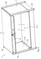
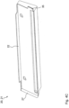
- the Figures 1 and 2 show the piece of furniture 1 according to the invention. In the embodiment, it is a free-standing cupboard.
- the piece of furniture 1 could, however, also be part of a shelving system. This includes, for example, a corresponding shelf compartment.
- the piece of furniture 1 comprises a first side wall 2 and a second side wall 3, as well as a rear wall 4, a base arrangement 5 and a cover arrangement 6.
- the base arrangement 5 is shown without a corresponding shelf. These delimit a receiving space 8.
- an opening 7 is provided through which the receiving space 8 is accessible.
- a closure flap 10 is also provided, which can be moved between an open position ( Figure 2 ), in which the receiving space 8 is accessible from outside the piece of furniture 1 and a closed position ( Figure 1 ), in which the opening 7 is closed by the closure flap 10, can be moved back and forth.
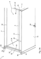
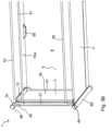
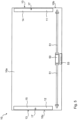
- FIG. 3A and 3B further views of the piece of furniture 1 with the lid assembly 6 removed are shown.
- a first hanging frame 20 and a second hanging frame 21 can be seen here.
- the wording "first” can also be understood as “left” when looking at the opening 7 from above.
- the wording “second” can also be understood as “right” when looking at the opening 7 from above.
- the first suspension frame 20 rests on an upper end face 2a of the first side wall 2. This upper end face 2a extends in the direction of the cover arrangement 6.
- the second suspension frame 21, on the other hand, rests on an upper end face 3a of the second side wall 3, which also points in the direction of the cover arrangement 6.
- first guide device 11 (see e.g. Figure 5 ), which is arranged in the area of a first side of the closure flap 10 and is in mechanical contact with the first suspension frame 20 over the entire path of movement of the closure flap 10.
- second guide device 12 which is arranged in the area of a second side of the closure flap 10 and is in mechanical contact with the second suspension frame 21 over the entire path of movement of the closure flap 10.
- the guide devices 11 and 12 are in particular in Figure 5 shown.
- the Figures 6A and 6B show further embodiments of the first and second guide devices 11, 12.
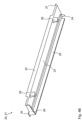
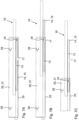
- the Figures 4A , 4B and 4C describe the structure of the first and second suspension frames 20, 21.
- the second (right) suspension frame 21 is shown in the figures.
- the first suspension frame 20 comprises a corresponding mirrored structure.
- the reference numerals for the individual parts of the second suspension frame 21 are identical to those of the first suspension frame 20. Therefore, the same reference numerals are used.
- the first and second suspension frames 20, 21 comprise a support section 22 which rests on the respective upper end face 2a, 3a of the first and second side walls 2, 3.
- a contact section 23 which extends from the support section 22 in the direction of the base arrangement 5 (e.g. for preferably less than 8 cm, 7 cm, 6 cm, 5 cm or less than 4 cm) and ends at a distance from it.
- the contact section 23 runs on an inner side 2b or 3b of the first and second side walls 2, 3.
- an engagement device 24 is provided which is arranged on the contact section 23 in the region of the opening 7 and extends in the direction of the receiving space 8. This engagement device 24 is designed to engage in the respective first or second guide device 11, 12 of the closure flap 10.
- the engagement device 24 of the first or second suspension frame 20, 21 is, for example, pin-shaped. This can be, for example, a cylindrical projection or a pin.
- the free end of this engagement device 24 can be wider than an intermediate piece.
- the engagement device 24 also widens in the direction of the contact section 23. This increases the robustness of the engagement device 24 and ensures optimal force transfer.
- the first or second suspension frame 20, 21 also comprise a support web 25 which is formed on the contact section 23 (in particular in one piece) and extends in the direction of the receiving space 8.
- the support web 25 is preferably arranged in the area of the first or second suspension frame 20, 21 which is arranged closest to the base arrangement 5.
- the support web 25 is designed to hold the closure flap 10 in the open position in the area of its first or second side. This also makes guidance easier.
- the support web 25 is further away from the cover arrangement 6 than the engagement device 24.
- the engagement device 24 can be attached to one end of the support web 25, which is arranged in particular in the region of the opening 7.
- the engagement device 24 preferably protrudes into the receiving space 8 by the same distance as the support web 25.
- the engagement device 24 could also protrude further or less far into the receiving space 8 than the support web 25.
- the support web 25 of the first or second hanging frame 20, 21 preferably comprises a stop section 26.
- This stop section 26 extends from the support web 25 in the direction of the lid arrangement 6 or the support section 22.
- the closure flap 10 could preferably be brought into contact with this stop section 26 in the open position. Preferably, however, the closure flap 10 cannot be brought into contact with this stop section 26.
- the stop section 26 is instead used to position the first or second hanging frame 20, 21 in the cabinet.
- the stop section 26 rests on an inner side of the rear wall 4 and serves as a stop for the first or second hanging frame 20, 21 when positioning it on the respective first or second side wall 2, 3.
- the first and second suspension frames 20, 21 comprise a front contact section 27.
- the front contact section 27 can be brought into contact with or rests against a front end face 2c, 3c of the first and second side walls over a partial length thereof.
- the front contact section 27 can additionally be supported on the first and second front vertical columns 60.
- the first or second suspension frame 20, 21 further comprises a rear contact section 35 (see Figure 4b ) which rests over a partial length of the left end face 4a or the right end face 4b of the rear wall 4 on those of these end faces 4a, 4b.
- At least one support rod 30, 31 is preferably provided.
- Two support rods 30, 31 are provided which run parallel to one another.
- the at least one support rod 30, 31 is arranged on the contact section 23 of the first or second suspension frame 20, 21 and extends between the cover arrangement 6 and the closure flap 10 when the latter is in the open position.
- the contact section 23 of the first or second suspension frame 20, 21 comprises at least one holding device 28, 29.
- the respective holding device 28, 29 comprises a wall that runs around at least in sections. This extends in the direction of the receiving space 8. It delimits a corresponding holding space that is open at least in the direction of the other suspension frame 21, 20.
- One end of the support rod 30, 31 is arranged and held in the corresponding holding space.
- the holding space can also be open to another side (in particular perpendicular to the extension of the support rod 30, 31). This could enable the support rod 30, 31 to be so-called clipped into the holding device.
- the first and second guide devices 11, 12 are described and their interaction with the respective engagement device 24 of the first or second suspension frame 20, 21 is explained.
- the first or second guide device 11, 12 comprises a guide groove 13. This guide groove 13 is open in the opening position of the closure flap 10 in the direction of the first or second side wall 2, 3 and is designed to accommodate the respective engagement device 24 of the first or second suspension frame 20, 21.
- Figure 6A shows that the guide groove 13 is arranged in a respective first and second housing arrangement 14, 15.
- a first housing arrangement 14 and second housing arrangement 15 are shown in Figure 5 These are preferably attached to an inner side 10a of the closure flap 10 (e.g. screwed and/or glued).
- the housing arrangement 14, 15 preferably does not extend over the entire height of the closure flap 10.
- the housing arrangement 14, 15 preferably has a width of preferably less than 6 cm, 5 cm, 4 cm or less than 3 cm and a height (thickness) of preferably less than 3 cm, 2 cm and less than 1 cm.
- the guide groove 13 is adapted in its opening width to the engagement device 24 and is intended to ensure that the engagement device 24 slides back and forth.
- the guide groove 13 preferably has an opening width of less than 1 cm, 8 mm, 6 mm or less than 5 mm, but preferably more than 2 mm.
- the guide groove 13 preferably runs exclusively along a straight line in the region in which the engagement device 24 of the first or second suspension frame 20, 21 moves during the normal movement of the closure flap 10 from the open position to the closed position.
- the ends 16 of the guide groove 13 of the first or second guide device 11, 12 are preferably closed and serve as end stops in the open or closed state of the closure flap 10.
- elements such as screws could be inserted or screwed into the grooves in order to be able to adjust the end stop and thus the open position and the closed position.
- the distance between the left or right front side 10b, 10c of the closure flap 10 to the respective contact section 23 of the first or second suspension frame 20, 21 is smaller than the length of the engagement device 24 of the first or second suspension frame 20, 21.
- the engagement device 24 cannot be pulled off the front side of the closure flap 10.
- the first or second guide device 11, 12 comprises an insertion opening 17 through which the guide groove 13 is accessible.
- the insertion opening 17 is directed in the direction of the base arrangement 5 in the open position of the closure flap 10 or before this open position is reached (in a predominantly horizontal position of the closure flap 10).
- the insertion opening 17 of the first guide device 11 and the insertion opening 17 of the second guide device 12 are preferably at different distances from the upper and lower end faces of the closure flap 10, so that an accidental release of the engagement device 24 from both guide grooves 13 does not occur simultaneously.
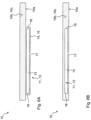
- closure flap 10 is in the open position.
- the engagement device 24 strikes a first closed end of the guide groove 13.
- a part of the closure flap 10 protrudes from the opening 7 of the receiving space.
- the largest part of the closure flap 10 is arranged within the receiving space 8.
- the closure flap 10 rests on the support web 25 of the respective first or second suspension frame 20, 21. In this case, it rests with its corresponding housing arrangement 14, 15 on this support web 25.
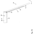
- FIG. 7C shows a view of a further movement of the closure flap 10 in the direction of the closed position. This can only be tilted minimally because it would immediately hit the lid arrangement 6 or the first or second support rod 30, 31 or the respective holding device 28, 29. This prevents the closure flap 10 from folding down accidentally. Only when the closure flap 10 has been moved into the end position (the engagement device 24 hits a second closed end of the guide groove 13) can the closure flap 10 be rotated by 90° in particular.
- a first and a second door stop 40, 41 are preferably provided.
- Figures 8A and 8B a first (left) doorstop 40 is described. This is inserted in the area of the first side wall 2 and the floor arrangement 6.
- a second doorstop 41 is inserted in the area of the second side wall 3 and the floor arrangement 6. Both doorstops 40, 41 are identical, but mirrored.
- the reference numerals of the first doorstop 40 also apply to the second doorstop 41.
- the first and second doorstops 40, 41 comprise a stop section 42 with a flap stop surface 43. This flap stop surface 43 is arranged in the area of the opening 7 of the piece of furniture 1.
- the closing flap 10 can be brought into contact with the respective flap stop surface 43 in the closed position.
- the first and second doorstops 40, 41 also comprise a support surface 44 which is inserted between the first and second side walls 2, 3 and the floor arrangement 6. There is also a contact section 45 which extends from the support surface 44 in the direction of the cover arrangement 6 (preferably by less than 6 cm, 5 cm, 4 cm but preferably more than 1 cm) and ends at a distance from the latter.
- the contact section 45 is arranged within the receiving space 8 and rests against an inner side 2b, 3b of the first or second side wall 2, 3.
- the stop section 42 of the first or second doorstop 40, 41 is arranged on the contact section 45 in the area of the opening 7 and extends in the direction of the receiving space 8. It preferably extends by less than 5 cm, 4 cm, or less than 3 cm into the receiving space 8. Preferably, however, it extends by more than 1 cm into the receiving space 8.
- the first or second doorstop 40, 41 preferably also comprises a front contacting section 46, wherein the front contacting section 46 rests against the front end face 2c, 3c of the first or second side wall 2, 3 over a partial length thereof.
- rear support surface 48 which can be inserted in the area between the rear wall 4 and the bottom wall 5.
- first or second door stop 40, 41 could also be integrated into the first or second suspension frame 20, 21.
- the flap stop surface 43 would extend from the contact section 23 into the receiving space 8 and run vertically in the area of the opening 7 in the direction of the floor arrangement 5.
- the closure flap 10 also comprises a locking device 50, which can switch back and forth between a closed state in which the closure flap 10 cannot be opened in the closed position and an open state in which the closure flap 10 can be opened in the closed position.
- the locking device 50 comprises a locking rod arrangement 51 (see Figure 5 ).
- the locking bar arrangement 51 is in the closed state in engagement with a lock stop surface 52 (see Figure 8A ) of the first or second door stop 40, 41. This lock stop surface 52 points in the direction of the rear wall 4.
- the lock stop surface 52 of the first or second door stop 40, 41 is according to Figure 8B formed by the stop section 42 of the first or second door stop 40, 41. It could also be formed by a further stop section which is arranged closer to the rear wall 4 than the already described stop section 42 with the flap striking surface 43.
- first and second side walls 2, 3 and the rear wall 4 as well as the base arrangement 5 and the cover arrangement 6 are attached to corresponding vertically extending columns 60.
- these columns 60 have a square cross-section.
- the columns 60 are preferably all rotated by 45° with respect to the first or second side walls 2, 3 or the rear wall 4.
- each of these columns 4 comprises corresponding side surfaces.
- each column 60 points in the direction of the receiving space 8.
- these side surfaces of the rear columns 60 are engaged by retaining elements that are inserted in the corners of the rear wall 4.
- the other retaining surfaces of these retaining elements then (encircle) the cover arrangement 6 or the base arrangement 5. This means that the rear wall 4 can be mounted without screws or adhesives.
- a holding element 53 in the form of a loop or a handle is attached to the closure flap 10 so that a user can easily open or close the closure flap 10.
Landscapes
- Engineering & Computer Science (AREA)
- Mechanical Engineering (AREA)
- Civil Engineering (AREA)
- Structural Engineering (AREA)
- Extensible Doors And Revolving Doors (AREA)
- Cabinets, Racks, Or The Like Of Rigid Construction (AREA)
- Hinges (AREA)
Claims (13)
- Meuble (1), notamment placard, présentant les particularités suivantes :- il est prévu un premier et un deuxième pan latéral (2, 3), un pan arrière (4), un plancher (5) et un plafond (6) qui délimitent un espace de rangement (8) ;- il est prévu une ouverture (7) entre les premier et deuxième pans latéraux (2, 3) ;- il est prévu un vantail de fermeture (10), lequel vantail de fermeture (10) est mobile entre une position d'ouverture, dans laquelle l'espace de rangement (8) est accessible depuis l'extérieur du meuble (1) par l'ouverture (7), et une position de fermeture dans laquelle l'ouverture (7) est fermée par le vantail de fermeture (10) ;- le vantail de fermeture (10) comprend un premier et un deuxième dispositif de guidage (11, 12) ;- il est prévu un premier et un deuxième bâti de suspension (20, 21) ;- le premier bâti de suspension (20) repose sur une face terminale supérieure (2a) du premier pan latéral (2) qui est tournée vers le plafond (6), et le deuxième bâti de suspension (21) repose sur une face terminale supérieure (3a) du deuxième pan latéral (3) qui est tournée vers le plafond (6) ;- le premier dispositif de guidage (11) est disposé dans la zone d'une première face du vantail de fermeture (10) et est en contact mécanique avec le premier bâti de suspension (20) sur toute la course de déplacement du vantail de fermeture (10), de la position d'ouverture jusqu'à la position de fermeture ; et- le deuxième dispositif de guidage (12) est disposé dans la zone d'une deuxième face du vantail de fermeture (10) et est en contact mécanique avec le deuxième bâti de suspension (21) sur toute la course de déplacement du vantail de fermeture (10), de la position d'ouverture jusqu'à la position de fermeture ;ledit meuble (1) étant caractérisé en ce que :- le premier bâti de suspension (20) comprend :a) une section de support (22) qui repose sur la face terminale supérieure (2a) du premier pan latéral (2) ;b) une section de contact (23) qui s'étend à partir de la section de support (22) en direction du plancher (5) et se termine à distance de celui-ci en reposant, à l'intérieur de l'espace de rangement (8), sur une face intérieure (2b) du premier pan latéral (2) ;c) un dispositif d'emboîtement (24) qui est disposé sur la section de contact (23) dans la zone de l'ouverture (7) en s'étendant en direction de l'espace de rangement (8) et est conçu pour s'emboîter dans le premier dispositif de guidage (11) du vantail de fermeture (10) ;et/ou- le deuxième bâti de suspension (21) comprend :a) une section de support (22) qui repose sur la face terminale supérieure (3a) du deuxième pan latéral (3);b) une section de contact (23) qui s'étend à partir de la section de support (22) en direction du plancher (5) et se termine à distance de celui-ci en reposant, à l'intérieur de l'espace de rangement (8), sur une face intérieure (3b) du deuxième pan latéral (3) ;c) un dispositif d'emboîtement (24) qui est disposé sur la section de contact (23) dans la zone de l'ouverture (7) en s'étendant en direction de l'espace de rangement (8) et est conçu pour s'emboîter dans le deuxième dispositif de guidage (12) du vantail de fermeture (10) ;et/ou- le premier dispositif de guidage (11) comprend une rainure de guidage (13) qui est ouverte, dans la position d'ouverture du vantail de fermeture (10), en direction du premier pan latéral (2) et est conçue pour recevoir un dispositif d'emboîtement (24) du premier bâti de suspension (20) ;
et/ou- le deuxième dispositif de guidage (12) comprend une rainure de guidage (13) qui est ouverte, dans la position d'ouverture du vantail de fermeture (10), en direction du deuxième pan latéral (3) et est conçue pour recevoir un dispositif d'emboîtement (24) du deuxième bâti de suspension (21). - Meuble (1) selon la revendication 1, caractérisé par les particularités suivantes :- le premier bâti de suspension (20) comprend une traverse de support (25) qui est formée sur la section de contact (23) en s'étendant en direction de l'espace de rangement (8) et est conçue pour maintenir le vantail de fermeture (10), en position d'ouverture, dans la zone de son premier côté, et/ou- le deuxième bâti de suspension (21) comprend une traverse de support (25) qui est formée sur la section de contact (23) en s'étendant en direction de l'espace de rangement (8) et est conçue pour maintenir le vantail de fermeture (10), en position d'ouverture, dans la zone de son deuxième côté.
- Meuble (1) selon la revendication 1 ou 2, caractérisé par les particularités suivantes :- il est prévu au moins une barre de support (30, 31) ;- l'au moins une barre de support (30, 31) est disposée sur la section de contact (23) du premier bâti de suspension (20) et sur la section de contact (23) du deuxième bâti de suspension (21) et s'étend entre le plafond (6) et le vantail de fermeture (10) lorsque ce dernier est en position d'ouverture.
- Meuble (1) selon l'une des revendications précédentes, caractérisé par les particularités suivantes :- le premier bâti de suspension (20) est d'un seul tenant et/ou le premier bâti de suspension (20) comprend du plastique ou en est constitué, et/ou- le deuxième bâti de suspension (21) est d'un seul tenant et/ou le deuxième bâti de suspension (21) comprend du plastique ou en est constitué ; et/ou
- Meuble (1) selon l'une des revendications précédentes, caractérisé par les particularités suivantes :- le premier bâti de suspension (20) est monté sur le premier pan latéral (2) sans vis et/ou sans colle et/ou sans pression et peut être retiré du premier pan latéral (2) sans laisser de traces, et/ou- le deuxième bâti de suspension (21) est monté sur le deuxième pan latéral (3) sans vis et/ou sans colle et/ou sans pression et peut être retiré du deuxième pan latéral (3) sans laisser de traces.
- Meuble (1) selon l'une des revendications précédentes, caractérisé par les particularités suivantes :- le premier pan latéral (2) est dépourvu de rainure servant à guider le vantail de verrouillage (10) et/ou à fixer le premier bâti de suspension (20), et/ou- le deuxième pan latéral (3) est dépourvu de rainure servant à guider le vantail de verrouillage (10) et/ou à fixer le deuxième bâti de suspension (21).
- Meuble (1) selon l'une des revendications précédentes, caractérisé par les particularités suivantes :- il est prévu une première butée de porte (40), laquelle première butée de porte (40) est disposée dans la zone du premier pan latéral (2) et du plancher (5) et présente une section de butée (42) dotée d'une surface de butée de vantail (43) dans la zone de l'ouverture (7) du meuble (1), ledit vantail de fermeture (10) en position de fermeture pouvant être mis en contact avec la surface de butée de vantail (43), et/ou- il est prévu une deuxième butée de porte (41), laquelle deuxième butée de porte (41) est disposée dans la zone du deuxième pan latéral (3) et du plancher (5) et présente une section de butée (42) dotée d'une surface de butée de vantail (43) dans la zone de l'ouverture (7) du meuble (1), ledit vantail de fermeture (10) en position de fermeture pouvant être mis en contact avec la surface de butée de vantail (43).
- Meuble (1) selon la revendication 7, caractérisé par les particularités suivantes :- la première butée de porte (40) comprend :a) une surface d'appui (44) qui loge entre le premier pan latéral (2) et le plancher (5) ;b) une section de contact (45) qui s'étend depuis la surface d'appui (44) en direction du plafond (6) et se termine à distance de celui-ci en reposant, à l'intérieur de l'espace de rangement (8), sur une surface intérieure (2b) du premier pan latéral (2) ;et/ou- le deuxième arrêt de porte (41) comprend :a) une surface d'appui (44) qui loge entre le deuxième pan latéral (3) et le plancher (5) ;b) une section de contact (45) qui s'étend depuis la surface d'appui (44) en direction du plafond (6) et se termine à distance de celui-ci en reposant, à l'intérieur de l'espace de rangement (8), sur la face intérieure (3b) du deuxième pan latéral (3).
- Meuble (1) selon la revendication 7 ou 8, caractérisé par les particularités suivantes :- la section de butée (42) de la première butée de porte (40) est disposée sur la section de contact (45) dans la zone de l'ouverture (7) et s'étend en direction de l'espace de rangement (6), et/ou- la section de butée (42) de la deuxième butée de porte (40) est disposée sur la section de contact (45) dans la zone de l'ouverture (7) et s'étend en direction de l'espace de rangement (8).
- Meuble (1) selon l'une des revendications 7 à 9, caractérisé par les particularités suivantes :- la première butée de porte (40) comprend une section de stabilisation avant (46), laquelle section de stabilisation avant (46) repose contre une face terminale avant (2c) du premier pan latéral (2) sur une longueur partielle de la face terminale avant (2c), et/ou la première butée de porte (40) comprend une section de stabilisation arrière (47), laquelle section de stabilisation arrière (47) repose contre une face terminale de gauche (4a) du pan arrière (4) sur une longueur partielle de cette face terminale de gauche (4a), et/ou la première butée de porte (40) comprend une surface d'appui arrière (48), laquelle surface d'appui arrière (48) repose dans une zone située entre le pan arrière (4) et le plancher (5) ; et/ou- la deuxième butée de porte (41) comprend une section de stabilisation avant (46), laquelle section de stabilisation avant (46) repose contre une face terminale avant (3c) du deuxième pan latéral (3) sur une longueur partielle de la face terminale avant (3c), et/ou la deuxième butée de porte (41) comprend une section de stabilisation arrière (47), laquelle section de stabilisation arrière (47) repose contre une face terminale de droite (4b) du pan arrière (4) sur une longueur partielle de cette face terminale de droite (4b), et/ou la deuxième butée de porte (41) comprend une surface d'appui arrière (48), laquelle surface d'appui arrière (48) repose dans une zone située entre le pan arrière (4) et le plancher (5).
- Meuble (1) selon l'une des revendications précédentes, caractérisé par les particularités suivantes :- le vantail de fermeture (10) comprend un dispositif de verrouillage (50), lequel dispositif de verrouillage (50) est mobile entre un état fermé dans lequel le vantail de fermeture (10), lorsqu'il se trouve en position de fermeture, ne peut pas être ouvert et un état ouvert dans lequel le vantail de fermeture (10), lorsqu'il se trouve en position de fermeture, peut être ouvert ;- le dispositif de verrouillage (50) comprend un ensemble de barres de verrouillage (51) ;- l'ensemble de barres de verrouillage (51) peut, dans ledit état fermé, être amené à s'enclencher dans une surface de butée de verrouillage (52) de la première butée de porte (40), ladite surface de butée de verrouillage (52) de la première butée de porte (40) étant tournée vers le pan arrière (4) ; et/ou- l'ensemble de barres de verrouillage (51) peut, dans ledit état fermé, être amené à s'enclencher dans une surface de butée de verrouillage (52) de la deuxième butée de porte (41), ladite surface de butée de verrouillage (52) de la deuxième butée de porte (41) étant tournée vers le pan arrière (4).
- Meuble (1) selon l'une des revendications précédentes, caractérisé par les particularités suivantes :- il est prévu un premier montant avant et un premier montant arrière (60) ;- il est prévu un deuxième montant avant et un deuxième montant arrière (60) ;- le premier pan latéral (2) est disposé entre le premier montant avant et le premier montant arrière (60) ;- le deuxième pan latéral (3) est disposé entre le deuxième montant avant et le deuxième montant arrière (60) ;- le pan arrière (4) est disposé entre les premier montant arrière et deuxième montant arrière (60) ;- l'ouverture (7) est réalisée entre les premier et deuxième montants avant (60).
- Meuble (1) selon la revendication 12, caractérisé par les particularités suivantes :- les premiers montants avant et arrière (60) ont une section transversale carrée ;- les deuxièmes montants avant et arrière (60) ont une section transversale carrée ;- les premiers montants avant et arrière (60) sont orientés de telle façon que les surfaces latérales des premiers montants avant et arrière (60) sont à 45° par rapport aux surfaces latérales du premier pan latéral (2) et du pan arrière (4) ;- les deuxièmes montants avant et arrière (60) sont orientés de telle façon que les surfaces latérales des deuxièmes montants avant et arrière (60) sont à 45° par rapport aux surfaces latérales du deuxième pan latéral (3) et du pan arrière (4).
Applications Claiming Priority (1)
| Application Number | Priority Date | Filing Date | Title |
|---|---|---|---|
| PCT/IB2020/000038 WO2021161056A1 (fr) | 2020-02-14 | 2020-02-14 | Meuble, en particulier armoire |
Publications (2)
| Publication Number | Publication Date |
|---|---|
| EP4022158A1 EP4022158A1 (fr) | 2022-07-06 |
| EP4022158B1 true EP4022158B1 (fr) | 2024-10-23 |
Family
ID=69844859
Family Applications (1)
| Application Number | Title | Priority Date | Filing Date |
|---|---|---|---|
| EP20711639.3A Active EP4022158B1 (fr) | 2020-02-14 | 2020-02-14 | Meuble, en particulier armoire |
Country Status (4)
| Country | Link |
|---|---|
| US (1) | US12241297B2 (fr) |
| EP (1) | EP4022158B1 (fr) |
| ES (1) | ES3004388T3 (fr) |
| WO (1) | WO2021161056A1 (fr) |
Families Citing this family (2)
| Publication number | Priority date | Publication date | Assignee | Title |
|---|---|---|---|---|
| USD1092107S1 (en) * | 2021-03-22 | 2025-09-09 | Jason Miller | Cabinet |
| CN218791196U (zh) * | 2022-09-22 | 2023-04-07 | 浙江致派工贸有限公司 | 一种鞋盒 |
Family Cites Families (13)
| Publication number | Priority date | Publication date | Assignee | Title |
|---|---|---|---|---|
| US3716282A (en) * | 1970-10-12 | 1973-02-13 | Miller H Inc | Drawer, tray-shelf and supporting structures therefor |
| US3794401A (en) * | 1971-10-20 | 1974-02-26 | Wright Barry Corp | Door guide |
| DE8434693U1 (de) | 1984-11-27 | 1985-03-07 | Fritz Schäfer GmbH, 5908 Neunkirchen | Stapeltransportkasten mit Kufen |
| US4591214A (en) * | 1985-03-01 | 1986-05-27 | Knoll International, Inc. | Cabinet closure assembly |
| US4615570A (en) * | 1985-04-29 | 1986-10-07 | Herman Miller, Inc. | Flipper door mounting assembly for cabinet |
| US5050944A (en) * | 1990-12-19 | 1991-09-24 | Haworth, Inc. | Over or under flipper door mounting |
| US5104080A (en) * | 1991-01-14 | 1992-04-14 | The Ducane Company, Inc. | Slidable shelf for outdoor grills |
| US5893616A (en) | 1997-05-15 | 1999-04-13 | Steelcase, Inc. | Knock-down hang-on storage unit for portable partition systems |
| DE20209103U1 (de) | 2002-06-12 | 2002-09-19 | Obermüller, Barbara, 91054 Erlangen | Schiebespiel mit Spielsteinen und einem Spielfeld |
| DE20307207U1 (de) | 2003-05-09 | 2004-09-16 | Paul Hettich Gmbh & Co. | Dreh-Schiebetür-Beschlag für Klappen oder Türen eines Schrankmöbels |
| ATE383489T1 (de) | 2003-10-29 | 2008-01-15 | Steelcase Sa | Tür mit versetzter drehachse |
| DE102008026381A1 (de) | 2008-06-02 | 2009-12-03 | BSH Bosch und Siemens Hausgeräte GmbH | Türablagefach für ein Kältegerät |
| DE102011109552B4 (de) | 2011-08-05 | 2015-04-30 | Steelcase Werndl Ag | Beschlagsystem zum Führen einer Verschlussklappe eines Möbelstücks sowie ein Möbelstück mit diesem |
-
2020
- 2020-02-14 EP EP20711639.3A patent/EP4022158B1/fr active Active
- 2020-02-14 US US17/759,661 patent/US12241297B2/en active Active
- 2020-02-14 WO PCT/IB2020/000038 patent/WO2021161056A1/fr not_active Ceased
- 2020-02-14 ES ES20711639T patent/ES3004388T3/es active Active
Also Published As
| Publication number | Publication date |
|---|---|
| WO2021161056A1 (fr) | 2021-08-19 |
| ES3004388T3 (en) | 2025-03-12 |
| US20230061256A1 (en) | 2023-03-02 |
| EP4022158A1 (fr) | 2022-07-06 |
| US12241297B2 (en) | 2025-03-04 |
Similar Documents
| Publication | Publication Date | Title |
|---|---|---|
| EP1868465B1 (fr) | Compartiment telescopique destine a un appareil frigorifique | |
| DE2412114A1 (de) | Vorrichtung zum verriegeln bestimmter von mehreren herausziehbaren aufbewahrungseinheiten bei einer aufbewahrungseinrichtung, z.b. einem schrank | |
| EP3467414B1 (fr) | Porte pour un appareil électroménager frigorifique pourvue d'un même dispositif permettant le montage dans les rainures latérales des côtés longitudinaux opposés ainsi que dispositif électroménager frigorifique et procédé de fabrication d'une porte | |
| WO1994015049A1 (fr) | Dispositif de fermeture pour portes de boitiers ou de placards | |
| EP1881775B1 (fr) | Dispositif d'extraction telescopique | |
| AT398516B (de) | Schubkastenauszug | |
| EP4022158B1 (fr) | Meuble, en particulier armoire | |
| EP1848942B1 (fr) | Appareil frigorifique a support de denrees refrigerees telescopique | |
| EP1592323A1 (fr) | Ensemble de rails telescopiques et appareil frigorifique pourvu d'un tel ensemble | |
| EP1846711B1 (fr) | Appareil a refroidir dote d'un porte-produits a refroidir coulissant | |
| EP4048122B1 (fr) | Combinaison d'un element de mouvement et d'un element de synchronisation pour des rails de tiroir | |
| EP3191779B1 (fr) | Appareil frigorifique avec caisson extractible | |
| EP3189749B1 (fr) | Guidage télescopique pour une partie de meuble mobile | |
| AT398517B (de) | Schublade | |
| DE10237138A1 (de) | Absteller für ein Kältegerät | |
| DE19818269A1 (de) | Diagonal-Einstecksystem | |
| DE29921641U1 (de) | Haushalts-Einbaukühlschrank mit Vorrichtungen zur Feinregulierung der Position der vorderen Abdeckplatten | |
| EP0293637B1 (fr) | Armoire à cadre pour tiroir munie d'une plaque de recouvrement rabattable | |
| EP2059744A1 (fr) | Appareil frigorifique comprenant un contenant qui peut être refermé par des portes coulissantes | |
| EP0698707B1 (fr) | Dispositif de verrouillage central pour chariot porte-outils | |
| EP0446452B1 (fr) | Dispositif pour armoire | |
| DE4441740C2 (de) | Möbelsystem | |
| DE29509556U1 (de) | Schaltschrank mit Montageplatte | |
| DE102015119991A1 (de) | Haltevorrichtung für einen Regalboden an einer Regalwand und Regal mit einer solchen Haltevorrichtung | |
| DE9313325U1 (de) | Regalsystem |
Legal Events
| Date | Code | Title | Description |
|---|---|---|---|
| STAA | Information on the status of an ep patent application or granted ep patent |
Free format text: STATUS: UNKNOWN |
|
| STAA | Information on the status of an ep patent application or granted ep patent |
Free format text: STATUS: THE INTERNATIONAL PUBLICATION HAS BEEN MADE |
|
| PUAI | Public reference made under article 153(3) epc to a published international application that has entered the european phase |
Free format text: ORIGINAL CODE: 0009012 |
|
| STAA | Information on the status of an ep patent application or granted ep patent |
Free format text: STATUS: REQUEST FOR EXAMINATION WAS MADE |
|
| 17P | Request for examination filed |
Effective date: 20220401 |
|
| AK | Designated contracting states |
Kind code of ref document: A1 Designated state(s): AL AT BE BG CH CY CZ DE DK EE ES FI FR GB GR HR HU IE IS IT LI LT LU LV MC MK MT NL NO PL PT RO RS SE SI SK SM TR |
|
| STAA | Information on the status of an ep patent application or granted ep patent |
Free format text: STATUS: EXAMINATION IS IN PROGRESS |
|
| 17Q | First examination report despatched |
Effective date: 20230116 |
|
| DAV | Request for validation of the european patent (deleted) | ||
| DAX | Request for extension of the european patent (deleted) | ||
| GRAP | Despatch of communication of intention to grant a patent |
Free format text: ORIGINAL CODE: EPIDOSNIGR1 |
|
| STAA | Information on the status of an ep patent application or granted ep patent |
Free format text: STATUS: GRANT OF PATENT IS INTENDED |
|
| INTG | Intention to grant announced |
Effective date: 20240214 |
|
| GRAJ | Information related to disapproval of communication of intention to grant by the applicant or resumption of examination proceedings by the epo deleted |
Free format text: ORIGINAL CODE: EPIDOSDIGR1 |
|
| STAA | Information on the status of an ep patent application or granted ep patent |
Free format text: STATUS: EXAMINATION IS IN PROGRESS |
|
| GRAS | Grant fee paid |
Free format text: ORIGINAL CODE: EPIDOSNIGR3 |
|
| STAA | Information on the status of an ep patent application or granted ep patent |
Free format text: STATUS: GRANT OF PATENT IS INTENDED |
|
| GRAP | Despatch of communication of intention to grant a patent |
Free format text: ORIGINAL CODE: EPIDOSNIGR1 |
|
| INTC | Intention to grant announced (deleted) | ||
| INTG | Intention to grant announced |
Effective date: 20240702 |
|
| GRAA | (expected) grant |
Free format text: ORIGINAL CODE: 0009210 |
|
| STAA | Information on the status of an ep patent application or granted ep patent |
Free format text: STATUS: THE PATENT HAS BEEN GRANTED |
|
| AK | Designated contracting states |
Kind code of ref document: B1 Designated state(s): AL AT BE BG CH CY CZ DE DK EE ES FI FR GB GR HR HU IE IS IT LI LT LU LV MC MK MT NL NO PL PT RO RS SE SI SK SM TR |
|
| REG | Reference to a national code |
Ref country code: GB Ref legal event code: FG4D Free format text: NOT ENGLISH |
|
| REG | Reference to a national code |
Ref country code: CH Ref legal event code: EP |
|
| REG | Reference to a national code |
Ref country code: DE Ref legal event code: R096 Ref document number: 502020009559 Country of ref document: DE |
|
| REG | Reference to a national code |
Ref country code: IE Ref legal event code: FG4D Free format text: LANGUAGE OF EP DOCUMENT: GERMAN |
|
| REG | Reference to a national code |
Ref country code: LT Ref legal event code: MG9D |
|
| REG | Reference to a national code |
Ref country code: NL Ref legal event code: MP Effective date: 20241023 |
|
| REG | Reference to a national code |
Ref country code: ES Ref legal event code: FG2A Ref document number: 3004388 Country of ref document: ES Kind code of ref document: T3 Effective date: 20250312 |
|
| PG25 | Lapsed in a contracting state [announced via postgrant information from national office to epo] |
Ref country code: NL Free format text: LAPSE BECAUSE OF FAILURE TO SUBMIT A TRANSLATION OF THE DESCRIPTION OR TO PAY THE FEE WITHIN THE PRESCRIBED TIME-LIMIT Effective date: 20241023 |
|
| PG25 | Lapsed in a contracting state [announced via postgrant information from national office to epo] |
Ref country code: NL Free format text: LAPSE BECAUSE OF FAILURE TO SUBMIT A TRANSLATION OF THE DESCRIPTION OR TO PAY THE FEE WITHIN THE PRESCRIBED TIME-LIMIT Effective date: 20241023 |
|
| PG25 | Lapsed in a contracting state [announced via postgrant information from national office to epo] |
Ref country code: IS Free format text: LAPSE BECAUSE OF FAILURE TO SUBMIT A TRANSLATION OF THE DESCRIPTION OR TO PAY THE FEE WITHIN THE PRESCRIBED TIME-LIMIT Effective date: 20250223 Ref country code: PT Free format text: LAPSE BECAUSE OF FAILURE TO SUBMIT A TRANSLATION OF THE DESCRIPTION OR TO PAY THE FEE WITHIN THE PRESCRIBED TIME-LIMIT Effective date: 20250224 Ref country code: HR Free format text: LAPSE BECAUSE OF FAILURE TO SUBMIT A TRANSLATION OF THE DESCRIPTION OR TO PAY THE FEE WITHIN THE PRESCRIBED TIME-LIMIT Effective date: 20241023 |
|
| PGFP | Annual fee paid to national office [announced via postgrant information from national office to epo] |
Ref country code: DE Payment date: 20250227 Year of fee payment: 6 |
|
| PG25 | Lapsed in a contracting state [announced via postgrant information from national office to epo] |
Ref country code: FI Free format text: LAPSE BECAUSE OF FAILURE TO SUBMIT A TRANSLATION OF THE DESCRIPTION OR TO PAY THE FEE WITHIN THE PRESCRIBED TIME-LIMIT Effective date: 20241023 |
|
| PG25 | Lapsed in a contracting state [announced via postgrant information from national office to epo] |
Ref country code: BG Free format text: LAPSE BECAUSE OF FAILURE TO SUBMIT A TRANSLATION OF THE DESCRIPTION OR TO PAY THE FEE WITHIN THE PRESCRIBED TIME-LIMIT Effective date: 20241023 |
|
| PGFP | Annual fee paid to national office [announced via postgrant information from national office to epo] |
Ref country code: ES Payment date: 20250303 Year of fee payment: 6 |
|
| PG25 | Lapsed in a contracting state [announced via postgrant information from national office to epo] |
Ref country code: NO Free format text: LAPSE BECAUSE OF FAILURE TO SUBMIT A TRANSLATION OF THE DESCRIPTION OR TO PAY THE FEE WITHIN THE PRESCRIBED TIME-LIMIT Effective date: 20250123 |
|
| PG25 | Lapsed in a contracting state [announced via postgrant information from national office to epo] |
Ref country code: LV Free format text: LAPSE BECAUSE OF FAILURE TO SUBMIT A TRANSLATION OF THE DESCRIPTION OR TO PAY THE FEE WITHIN THE PRESCRIBED TIME-LIMIT Effective date: 20241023 Ref country code: GR Free format text: LAPSE BECAUSE OF FAILURE TO SUBMIT A TRANSLATION OF THE DESCRIPTION OR TO PAY THE FEE WITHIN THE PRESCRIBED TIME-LIMIT Effective date: 20250124 |
|
| PG25 | Lapsed in a contracting state [announced via postgrant information from national office to epo] |
Ref country code: PL Free format text: LAPSE BECAUSE OF FAILURE TO SUBMIT A TRANSLATION OF THE DESCRIPTION OR TO PAY THE FEE WITHIN THE PRESCRIBED TIME-LIMIT Effective date: 20241023 |
|
| PGFP | Annual fee paid to national office [announced via postgrant information from national office to epo] |
Ref country code: FR Payment date: 20250225 Year of fee payment: 6 |
|
| PGFP | Annual fee paid to national office [announced via postgrant information from national office to epo] |
Ref country code: GB Payment date: 20250227 Year of fee payment: 6 |
|
| PG25 | Lapsed in a contracting state [announced via postgrant information from national office to epo] |
Ref country code: RS Free format text: LAPSE BECAUSE OF FAILURE TO SUBMIT A TRANSLATION OF THE DESCRIPTION OR TO PAY THE FEE WITHIN THE PRESCRIBED TIME-LIMIT Effective date: 20250123 |
|
| PG25 | Lapsed in a contracting state [announced via postgrant information from national office to epo] |
Ref country code: SM Free format text: LAPSE BECAUSE OF FAILURE TO SUBMIT A TRANSLATION OF THE DESCRIPTION OR TO PAY THE FEE WITHIN THE PRESCRIBED TIME-LIMIT Effective date: 20241023 |
|
| PG25 | Lapsed in a contracting state [announced via postgrant information from national office to epo] |
Ref country code: DK Free format text: LAPSE BECAUSE OF FAILURE TO SUBMIT A TRANSLATION OF THE DESCRIPTION OR TO PAY THE FEE WITHIN THE PRESCRIBED TIME-LIMIT Effective date: 20241023 |
|
| PG25 | Lapsed in a contracting state [announced via postgrant information from national office to epo] |
Ref country code: EE Free format text: LAPSE BECAUSE OF FAILURE TO SUBMIT A TRANSLATION OF THE DESCRIPTION OR TO PAY THE FEE WITHIN THE PRESCRIBED TIME-LIMIT Effective date: 20241023 |
|
| PG25 | Lapsed in a contracting state [announced via postgrant information from national office to epo] |
Ref country code: RO Free format text: LAPSE BECAUSE OF FAILURE TO SUBMIT A TRANSLATION OF THE DESCRIPTION OR TO PAY THE FEE WITHIN THE PRESCRIBED TIME-LIMIT Effective date: 20241023 |
|
| REG | Reference to a national code |
Ref country code: DE Ref legal event code: R097 Ref document number: 502020009559 Country of ref document: DE |
|
| PG25 | Lapsed in a contracting state [announced via postgrant information from national office to epo] |
Ref country code: SK Free format text: LAPSE BECAUSE OF FAILURE TO SUBMIT A TRANSLATION OF THE DESCRIPTION OR TO PAY THE FEE WITHIN THE PRESCRIBED TIME-LIMIT Effective date: 20241023 |
|
| PG25 | Lapsed in a contracting state [announced via postgrant information from national office to epo] |
Ref country code: CZ Free format text: LAPSE BECAUSE OF FAILURE TO SUBMIT A TRANSLATION OF THE DESCRIPTION OR TO PAY THE FEE WITHIN THE PRESCRIBED TIME-LIMIT Effective date: 20241023 |
|
| PG25 | Lapsed in a contracting state [announced via postgrant information from national office to epo] |
Ref country code: IT Free format text: LAPSE BECAUSE OF FAILURE TO SUBMIT A TRANSLATION OF THE DESCRIPTION OR TO PAY THE FEE WITHIN THE PRESCRIBED TIME-LIMIT Effective date: 20241023 |
|
| PLBE | No opposition filed within time limit |
Free format text: ORIGINAL CODE: 0009261 |
|
| STAA | Information on the status of an ep patent application or granted ep patent |
Free format text: STATUS: NO OPPOSITION FILED WITHIN TIME LIMIT |
|
| PG25 | Lapsed in a contracting state [announced via postgrant information from national office to epo] |
Ref country code: SE Free format text: LAPSE BECAUSE OF FAILURE TO SUBMIT A TRANSLATION OF THE DESCRIPTION OR TO PAY THE FEE WITHIN THE PRESCRIBED TIME-LIMIT Effective date: 20241023 |
|
| PG25 | Lapsed in a contracting state [announced via postgrant information from national office to epo] |
Ref country code: MC Free format text: LAPSE BECAUSE OF FAILURE TO SUBMIT A TRANSLATION OF THE DESCRIPTION OR TO PAY THE FEE WITHIN THE PRESCRIBED TIME-LIMIT Effective date: 20241023 |
|
| REG | Reference to a national code |
Ref country code: CH Ref legal event code: PL |
|
| 26N | No opposition filed |
Effective date: 20250724 |
|
| PG25 | Lapsed in a contracting state [announced via postgrant information from national office to epo] |
Ref country code: LU Free format text: LAPSE BECAUSE OF NON-PAYMENT OF DUE FEES Effective date: 20250214 |
|
| PG25 | Lapsed in a contracting state [announced via postgrant information from national office to epo] |
Ref country code: CH Free format text: LAPSE BECAUSE OF NON-PAYMENT OF DUE FEES Effective date: 20250228 |
|
| REG | Reference to a national code |
Ref country code: BE Ref legal event code: MM Effective date: 20250228 |
|
| PG25 | Lapsed in a contracting state [announced via postgrant information from national office to epo] |
Ref country code: BE Free format text: LAPSE BECAUSE OF NON-PAYMENT OF DUE FEES Effective date: 20250228 |
|
| PG25 | Lapsed in a contracting state [announced via postgrant information from national office to epo] |
Ref country code: IE Free format text: LAPSE BECAUSE OF NON-PAYMENT OF DUE FEES Effective date: 20250214 |