EP4022155B1 - Selbsteinstellende sonnenschutzbaugruppe - Google Patents
Selbsteinstellende sonnenschutzbaugruppe Download PDFInfo
- Publication number
- EP4022155B1 EP4022155B1 EP20856803.0A EP20856803A EP4022155B1 EP 4022155 B1 EP4022155 B1 EP 4022155B1 EP 20856803 A EP20856803 A EP 20856803A EP 4022155 B1 EP4022155 B1 EP 4022155B1
- Authority
- EP
- European Patent Office
- Prior art keywords
- mast
- sail
- ribs
- assembly
- pivot cap
- Prior art date
- Legal status (The legal status is an assumption and is not a legal conclusion. Google has not performed a legal analysis and makes no representation as to the accuracy of the status listed.)
- Active
Links
Images


Classifications
-
- E—FIXED CONSTRUCTIONS
- E04—BUILDING
- E04H—BUILDINGS OR LIKE STRUCTURES FOR PARTICULAR PURPOSES; SWIMMING OR SPLASH BATHS OR POOLS; MASTS; FENCING; TENTS OR CANOPIES, IN GENERAL
- E04H15/00—Tents or canopies, in general
- E04H15/28—Umbrella type tents
-
- A—HUMAN NECESSITIES
- A45—HAND OR TRAVELLING ARTICLES
- A45B—WALKING STICKS; UMBRELLAS; LADIES' OR LIKE FANS
- A45B23/00—Other umbrellas
-
- A—HUMAN NECESSITIES
- A45—HAND OR TRAVELLING ARTICLES
- A45B—WALKING STICKS; UMBRELLAS; LADIES' OR LIKE FANS
- A45B25/00—Details of umbrellas
- A45B25/02—Umbrella frames
-
- A—HUMAN NECESSITIES
- A45—HAND OR TRAVELLING ARTICLES
- A45B—WALKING STICKS; UMBRELLAS; LADIES' OR LIKE FANS
- A45B25/00—Details of umbrellas
- A45B25/06—Umbrella runners
-
- A—HUMAN NECESSITIES
- A45—HAND OR TRAVELLING ARTICLES
- A45B—WALKING STICKS; UMBRELLAS; LADIES' OR LIKE FANS
- A45B25/00—Details of umbrellas
- A45B25/10—Umbrella crowns
-
- A—HUMAN NECESSITIES
- A45—HAND OR TRAVELLING ARTICLES
- A45B—WALKING STICKS; UMBRELLAS; LADIES' OR LIKE FANS
- A45B25/00—Details of umbrellas
- A45B25/18—Covers; Means for fastening same
-
- A—HUMAN NECESSITIES
- A45—HAND OR TRAVELLING ARTICLES
- A45B—WALKING STICKS; UMBRELLAS; LADIES' OR LIKE FANS
- A45B25/00—Details of umbrellas
- A45B25/22—Devices for increasing the resistance of umbrellas to wind
-
- E—FIXED CONSTRUCTIONS
- E04—BUILDING
- E04H—BUILDINGS OR LIKE STRUCTURES FOR PARTICULAR PURPOSES; SWIMMING OR SPLASH BATHS OR POOLS; MASTS; FENCING; TENTS OR CANOPIES, IN GENERAL
- E04H15/00—Tents or canopies, in general
- E04H15/32—Parts, components, construction details, accessories, interior equipment, specially adapted for tents, e.g. guy-line equipment, skirts, thresholds
- E04H15/58—Closures; Awnings; Sunshades
-
- A—HUMAN NECESSITIES
- A45—HAND OR TRAVELLING ARTICLES
- A45B—WALKING STICKS; UMBRELLAS; LADIES' OR LIKE FANS
- A45B23/00—Other umbrellas
- A45B2023/0012—Ground supported umbrellas or sunshades on a single post, e.g. resting in or on a surface there below
-
- A—HUMAN NECESSITIES
- A45—HAND OR TRAVELLING ARTICLES
- A45B—WALKING STICKS; UMBRELLAS; LADIES' OR LIKE FANS
- A45B23/00—Other umbrellas
- A45B2023/0093—Sunshades or weather protections of other than umbrella type
-
- A—HUMAN NECESSITIES
- A45—HAND OR TRAVELLING ARTICLES
- A45B—WALKING STICKS; UMBRELLAS; LADIES' OR LIKE FANS
- A45B25/00—Details of umbrellas
- A45B25/10—Umbrella crowns
- A45B2025/105—Umbrella crowns movable with respect to the shaft
Definitions
- the presently disclosed subject matter is directed to a self-adjusting sun shade assembly and to a method using the same.
- Beach umbrellas are used to create an area shaded from the sunlight beneath the umbrella canopy. They are particularly useful at the beach where there is generally a lack of trees or roofed structures to provide shade. Because the skin of the beachgoer is largely exposed at the beach, there is a greater need to provide protection from harmful ultraviolet rays, which may cause sunburn or melanomas. Many beachgoers also require some form of shade to minimize heat discomfort. The shade and shelter provided by a beach umbrella is also useful in protecting the user's valuables and shielding perishable items from direct sunlight.
- Conventional beach umbrellas include a single central support pole with a pointed lower end that is inserted directly into the sand. Conventional umbrellas further include an overhead fabric covering attached to the support pole.
- the self-adjusting sun shade assembly according to the present invention is presented in claim 1.
- the method of using a self-adjusting sun shade assembly according to the present invention is presented in claim 11.
- the presently disclosed subject matter is directed to a self-adjusting sun shade assembly (e.g., an assembly that provides shade from the sun).
- the assembly comprises a pair of ribs defined by a first end and a second end, wherein the first end of each rib is attached to a pivot cap.
- the assembly further includes a sail with a front edge comprising a channel sized and shaped to house each rib such that the ribs extend across the edge.
- the assembly includes a mast comprising a first end and a second end, wherein the first end is operably connected to the pivot cap, wherein the pivot cap can freely rotate about the mast.
- the assembly comprises at least one support arm with a first end and a second end, wherein the first end of the support arm is attached to a rib and the second end of the support arm Is attached to a slider configured to move up and down the mast.
- the assembly comprises a tension adjuster that adjusts rotation of the pivot cap about the mast.
- the assembly comprises an anchor operably connected to the second end of the mast. The pivot cap, ribs, slider, and support arms are configured to rotate about the mast in response to blowing of the wind.
- the pivot cap rotates about the mast at an angle of about 0-360 degrees. In an example the pivot cap rotates about a top end of the mast (e.g., is configured to rotate about the top end of the mast).
- the ribs are configured at an angle of greater than 180 degrees relative to each other.
- one face of the pivot cap comprises a lock defined by a bridge comprising an opening and a slidable arm that moves to cover and expose the opening.
- a portion of sail material can be locked in between the bridge and slidable arm to lock it into position.
- the slider is configured as a collar that fits around the exterior circumference of the mast.
- the mast length is adjustable.
- the anchor is releasably attached to the second end of the mast.
- the anchor comprises an auger.
- auger refers to a member in which a spiral vane or multiple parallel vanes are provided about the perimeter of a shaft.
- the tension adjuster is configured to permit the pivot cap, slider, ribs, and support arms to freely rotate about the mast, not rotate about the mast, or any level of rotation therebetween.
- the pivot cap, slider, ribs, and support arms rotate as a single, attached unit.
- the sail channel comprises one or more apertures to facilitate insertion of the ribs into the channel.
- the sail channel comprises one or more apertures to allow direct contact between each rib and a corresponding support arm.
- the sail has a top face and a bottom face, and wherein the bottom face includes at least one conduit configured as a channel with an open mouth positioned adjacent to the channel, a closed back end, and a length parallel with the length of the sail.
- the sail has a top face and a bottom face and wherein at least one of the top or bottom faces comprises a coating.
- the sail has an opposed rear edge comprising an adjacent hem constructed from a durable material.
- the mast comprises at least one handle.
- the presently disclosed subject matter is directed to a method of using a sunshade.
- the method comprises positioning the anchor of a sun shade assembly in a support surface.
- the sun shade assembly comprises: a pair of ribs defined by a first end and a second end, wherein the first end of each rib is attached to a pivot cap; a sail with a front edge comprising a channel sized and shaped to house each rib such that the ribs extend across the edge; a mast comprising a first end and a second end, wherein the first end is operably connected to the pivot cap, wherein the pivot cap can freely rotate about the mast; at least one support arm with a first end and a second end, wherein the first end of the support arm is attached to a rib and the second end of the support arm is attached to a slider configured to move up and down the mast; a tension adjuster that adjusts rotation of the pivot cap about the mast; and an anchor operably connected to the second end of the mast.
- the method further includes adjusting
- the tension adjuster can be adjusted to allow the pivot cap, slider, ribs, and support arms to freely rotate about the mast, not rotate about the mast, or any level of rotation therebetween.
- the sail has a top face and a bottom face, and wherein the bottom face includes at least one conduit configured as a channel with an open mouth positioned adjacent to the channel, a closed back end, and a length parallel with the length of the sail.
- one face of the pivot cap comprises a lock defined by a bridge comprising and opening and a slidable arm that moves to cover and expose the opening.
- the sail has an opposed rear edge comprising an adjacent hem constructed from a durable material.
- the term "about”, when referring to a value or to an amount of mass, weight, time, volume, concentration, and/or percentage can encompass variations of, in an example +/-20%, in an example +/-10%, in an example +/-5%, in an example +/-1%, in an example +/-0.5%, and in an example +/-0.1%, from the specified amount, as such variations are appropriate in the disclosed packages and methods.
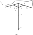
- Fig. 1 illustrates one embodiment of sun shade assembly 5.
- the assembly includes sail 20 that releasably attaches to a pair of ribs 10, providing shade to the user.
- At least one support arm 15 can be used to reinforce ribs 10.
- Mast 30 provides height to the assembly and includes anchor 35 that allows the assembly to be secured into a support surface (e.g., sand).
- the ribs and support arms rotate about the mast, thereby self-adjusting the direction of sail 20 in response to the wind blowing, as described in more detail below.
- the assembly further includes tension adjuster 25 that can be tightened or loosed to control the rotation of the ribs and support arms in response to wind conditions.
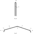
- Fig. 2a illustrates one embodiment of rib 10.
- the rib includes first end 11 and second end 12.
- the ribs can each include one or more joints 13 that can be folded, allowing the ribs to be easily stored when not in use, as illustrated in Figs. 2b and 2c .
- Any mechanism can be used to fold the ribs, such as (but not limited to) hinges, joints, and the like.
- a living hinge, a barrel hinge, spring hinge, butterfly hinge, flag hinge, H hinge, or any other pivotable member can be used.
- living hinge refers to a hinge integrally formed with two opposite portions of the same material.
- barrel hinge refers to a sectional barrel secured by a pivot.
- spring hinge refers to a spring-loaded hinge that applies force to secure the hinge in an open or closed configuration.
- Boilfly hinge refers to dovetail orInstitut hinges.
- flag hinge refers to hinges that can be taken apart with a fixed pin on one leaf, manufactured in a right-hand or left-hand configuration.
- An “H hinge” refers to a hinge shaped like an "H.”
- the ribs are non-foldable and remain in the fully extended state, even during storage.
- the ribs can be slightly offset relative to each other (e.g., are not 180 degrees apart). The offset nature allows the ribs to compensate for stretching of the sail.
- the angle 16 between ribs 10 can be about 180-300 degrees, as shown in Fig. 2d .
- the angle between ribs 10 can be at least/no more than about 180, 185, 190, 195, 200, 205, 210, 215, 220, 225, 230, 235, 240, 245, 250, 255, 260, 265, 270, 275, 280, 285, or 290 degrees.
- angle 16 is not limited and can be larger or smaller than the range set forth herein.
- the ribs can be fully folded, such as in a storage position, as shown in Fig. 2e .
- rib 10 can include extension 14 as shown in Fig. 2f .
- the extensions provide a decorative look the assembly when the sail is attached.
- Each extension can be attached to rib second end 12 using any desired method (e.g., adhesive, welding, clips, clamps, hinges, screws, bolts, magnets, etc.). It should be appreciated that extension 14 is optional.
- Ribs 10 can have any desired length.
- suitable lengths can include (but are not limited to) about 3-10 feet.
- the ribs can have a length of at least about (or no more than about) 3, 3.5, 4, 4.5, 5, 5.5, 6, 6.5, 7, 7.5, 8, 8.5, 9, 9.5, or 10 feet.
- the presently disclosed subject matter is not limited the length of each rib can be larger or smaller than the range given herein.
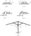
- the ribs are joined using pivot cap 40, as illustrated in Fig. 3a .
- the pivot cap joins ribs 10 and enables rotation of the ribs about mast 30.
- the pivot cap can freely rotate about the mast in response to wind conditions, as discussed in more detail below and as shown in Fig. 3b .
- the ribs can rotate in a clockwise or counterclockwise direction, depending on the wind direction. It should be appreciated that the ribs can join to pivot cap 40 using any mechanism (e.g., screws, bolts, clips, hinges, welding, adhesive, magnets, and the like).
- one face of pivot cap 40 includes bridge 94 comprising opening 93 and slidable arm 95 that can be used to releasably lock the sail into proper position, as shown in Figs. 3c-3e .
- a portion of the sail can be inserted into opening 94.
- Arm 95 can then be slid to trap the portion of the sail over the bridge, as shown in Figs. 3f and 3g .
- a portion of the sail is trapped between the bridge and the arm.
- the arm can be slid to expose opening 93, thereby allowing the sail to be removed.
- bridge refers to any device that has a raised portion with an opening configured therein.
- the arm can fully surround at least a segment of the raised bridge portion.
- the assembly can include one or more support arms 15 that provide stability to the ribs, allowing the assembly to support the sail even in high wind conditions.
- Each support arm includes first end 16 attached to rib 10 and second end 17 attached to slider 45.
- the support arms can be attached to the rib and slider using any known mechanism, such as the use of adhesives, welding, magnets, mechanical elements (screws, bolts, clips), and the like.
- the support arms are hingedly attached to the ribs and/or slider to allow for easy transitioning between positions.
- Slider 45 can move along mast 30 to fold or unfold the ribs and support arms.
- the slider can be configured as a collar that fits about the outer circumference of mast 30, as shown in Fig. 4b .
- the inner circumference of slider 45 is therefore at least slightly larger than the outer circumference of mast 30.
- the slider and support arms can rotate freely about the mast.
- the mast remains in a stationary position, while the slider (and attached support arms and ribs) rotate in response to the wind blowing.
- the slider can rotate in any direction (e.g., clockwise and counterclockwise).
- the slider can include retention element 2 to keep it from sliding down the length of the mast.
- the retention element can include any device that retains the slider in a desired position on the mast, such as (but not limited to) a removable ledge with an outer circumference larger than the inner circumference of the slider, clips, pins, clasps, and the like. The retention element therefore locks the slider at a desired location along the mast. In this way, the ribs and support arms can be maintained in the open configuration without the slider slipping to a lower position. Likewise, the slider can also be locked in a lower "storage" configuration along the mast (or any location therebetween).
- the slider can also be used to fold the ribs and support arms, such as when the assembly is transitioned to a storage configuration (e.g., not in use).
- a storage configuration e.g., not in use.
- the support arms and ribs are unfolded outward and thus sail 20 is unfolded, as shown in Fig. 4a .
- the support arms and ribs are folded to the storage position, as shown in Figs 4c and 4d . Therefore, the slider can travel on the mast in an upward direction to extend the ribs and support arms to a fully open configuration.
- the slider can also move downward along the mast to transition the ribs and support arms into a folded position.
- Ribs 10 and support arms 15 can have any desired cross-sectional shape.
- the ribs and support arms can be configured with a circular, oval, square, rectangular, triangular, pentagonal, hexagonal, octagonal, heart, diamond, or abstract cross-sectional shape.
- assembly 5 comprises mast 30 that reinforces ribs 10 and support arms 15, as well as provides height to the assembly, as shown in Fig. 5a .
- the mast further provides a base about which the ribs can rotate via pivot cap 40.
- the mast includes first end 31 operatively attached to pivot cap 40 and second end 32 attached to anchor 35.
- the mast can be permanently or releasably attached to the pivot cap and/or anchor.
- the pivot cap is attached to mast first end 31 using any known method.
- a screw, bolt, or other element 33 can be threaded through the pivot cap, extending into the mast as shown in Fig. 5b .
- the pivot cap attaches to the mast and still can rotate freely in a clockwise or counterclockwise direction.
- the pivot cap can have any desired shape and is not limited to the embodiment shown in Fig. 5b . Attachment of the pivot cap to the mast is further not limited.
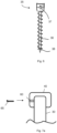
- the mast can include telescoping inner and outer tubes 41, 42.
- the term "telescoping" refers to a mechanical action of at least two longitudinal bodies of congruent cross-sections sliding relative to each other along a common longitudinal axis.
- inner tube 41 can be at least partially slidably disposed into the interior of outer tube 42.
- the diameter of the outer tube is larger than the diameter of the inner tube such that the inner tube can be housed within the interior of the outer tube.
- the mast can include any number of telescoping tubes.
- a locking pin can pass through one or more holes 43 configured in the outer tube to hold the mast at the desired length.
- the inner and outer tubes can cooperate with a locking screw to secure the mast height. It should be appreciated that the length of the mast can be locked using any known element, such as friction fit, screw fit, snap-fit, screws, bolts, and the like.
- the length of the mast can be adjusted using any known mechanism and is not limited to a telescoping arrangement.
- the mast can include a plurality of segments that can be added or removed as desired to achieve a suitable height.
- the length of mast 30 is not adjustable.
- mast 30 can have any desired cross-sectional shape.
- the mast can be configured with a circular, oval, square, rectangular, triangular, pentagonal, hexagonal, octagonal, heart, diamond, or abstract cross-sectional shape.
- Anchor broadly refers to any element that provides weight and/or a mechanism by which to secure assembly 5 into a support surface (e.g., sand).
- the anchor can be permanently attached to mast 30 using adhesives, welding, and the like.
- the anchor can be releasably attached to the mast using any of a wide variety of mechanical elements (e.g., screw knob 37 ).
- a releasably attached anchor allows for the replacement of the anchor depending on use conditions (e.g., beach sand versus grass or rock).
- Fig. 6 illustrates one embodiment of anchor 35 comprising auger 36 that can be configured as any type of spike, helical corkscrew, or shaft optionally having a threaded portion capable of being turned and embedding itself into a support surface (e.g., sand at a beach).
- Lower end 38 of the auger can be configured as a spike or pointed end to initiate insertion of the anchor into the support surface. Because auger 36 is inserted into a support surface, it does not rotate and remains in the inserted position until the user desires to remove it. Likewise, the mast does not rotate in response to wind conditions due to its attachment to the anchor.
- the disclosed assembly further includes tension adjuster 25 that allows a user to adjust the tension on the pivot cap relative to the mast easily and safely. In this way, a user can alter the amount of rotation ribs 10, support arms 15 and slider 45 have about mast 30 in response to wind conditions.
- the tension adjuster can be generally located adjacent to the pivot cap.
- the tension adjuster is also attached to mast 30 using any known mechanism (e.g., screws, bolts, clips, etc.).
- the pivot cap (and attached ribs, slider, and support arms) can freely rotate about the mast in response to the wind blowing.
- the tension adjuster can be tightened as desired by the user (e.g., when the wind is shifting back and forth) to stop or limit rotation of the pivot cap (and ribs, support arm, and slider) about the mast to maintain a more balanced assembly.
- the tension adjuster can be loosened to allow the pivot cap, ribs, support arms, and slider to freely rotate (e.g., 360 degrees) about the mast.
- the pivot cap, ribs, slider, and support arms have a more limited freedom to rotate (e.g., it takes a stronger gust of wind to rotate).
- the tension adjuster can be fully tightened such that the ribs, slider, and support arms cannot rotate relative to the mast.
- Tension adjuster 25 can have any desired configuration that allows a user to control the level of movement of the tension cap relative to the mast.
- the tension adjuster can include passageway 60 with actuator 65 (e.g., lever or screw) capable of contacting pivot cap 40, as shown in Figs. 7a and 7b . Adjusting the actuator through the passageway will increase or decrease the tension on the pivot cap. Specifically, if the actuator is tightened to fully contact the pivot cap, the pivot cap will be incapable of moving relative to the mast. Alternatively, if the actuator is loosened such that it does not fully contact or press against the mast, the pivot cap is free to rotate. Any degree of actuator tightening can therefore adjust the level of pivot cap rotation.
- actuator 65 e.g., lever or screw
- the tension adjuster can have any known configuration and is not limited to the embodiment described above.
- the tension adjuster can apply a force parallel, at an angle, or perpendicular to the tension it creates.
- the force can be generated by any known method, such as fixed displacement, stretching/compression of a spring, changing the volume of a gas, hydraulic pressure, or gravity.
- Tension adjuster 25 can therefore include any device that applies a force to create or maintain tension.
- actuator 65 can have any known configuration, such as (but not limited to) a lever, wrench, key, screw, handle, knob, bolt, and the like.
- the ribs, mast, support arms, pivot cap, tension adjuster, and anchor can be constructed from any desired material, such as (but not limited to) metal (e.g., aluminum, steel, brass, stainless steel, copper), plastic, wood, stone, or combinations thereof.
- metal e.g., aluminum, steel, brass, stainless steel, copper
- plastic e.g., polymethyl methacrylate
- wood e.g., polymethyl methacrylate, polymethyl methacrylate, polymethyl methacrylate, polymethyl methacrylate, polymethyl methacrylate, polymethyl methacrylate, polymethyl methacrylate, polymethyl methacrylate, polymethyl methacrylate, polymethyl methacrylate, polymethyl methacrylate, polymethyl methacrylate, polymethyl methacrylate, polymethyl methacrylate, polymethyl methacrylate, polymethyl methacrylate, polymethyl methacrylate, polymethyl methacrylate, polymethyl methacrylate, polymethyl methacrylate, polymethyl methacrylate, poly
- Assembly 5 further includes sail 20 that cooperates with ribs 10. As shown in Figs. 8a and 8b , the sail can include front edge 61, rear edge 62, and a pair of side edges 63. The sail further includes top face 70 and bottom face 71.
- Front edge 61 comprises channel 65 sized and shaped to house each rib 10, as shown in Figs. 8c .
- the front edge can be a straight edge, a curved edge, or have any known configuration.
- the ribs can be removed from channels 65 if desired by the user (e.g., to repair the sail or replace with a new sail).
- Channels 65 can be formed in the sail using any known method. For example, in an example the channel can be formed through sewing, welding, and the like. Such methods are well known in the art.
- each channel includes one or more apertures.
- each channel can include apertures 91 sized and shaped to allow each rib to be inserted into channel 65.
- the channel can further include one or more apertures 92 sized and shaped to allow each support arm to connect with the appropriate rib, as shown in Fig. 8d .
- Apertures 91, 92 can have any desired size and/or shape so long as they allow for insertion of a rib and/or connection of a support arm with a rib (e.g., through one or more screws, clips, and/or the like). Further, apertures 91, 92 can be positioned at any suitable position in the channel.
- bottom face 71 of the sail can include at least one closed conduit 72 that provides a passageway for the flow of the wind during use.
- Fig. 8e illustrates one embodiment of conduit 72 comprising open mouth 73 positioned adjacent to the sail front edge, length 74 and closed end 75.
- Fig 8f illustrates the flow of wind (represented by the arrows) as it enters open mouth 73, hits closed end 75 and then exits the open mouth.
- Conduit 72 provides added support for the sail, preventing or reducing excess flapping in the wind.
- the length of the conduit is the same as the length of the sail (i.e., the conduit extends the full length of the sail). In other embodiments, the conduit is configured to be shorter than the length of the sail, as shown in Figs. 8g and 8h . In an example the thickness of the conduit can taper as it reaches closed end 75, as shown in Fig. 8i .
- the conduit can have any cross-sectional shape, such as (but not limited to) square, rectangular, circular, oval, triangular, and the like.
- the sail can further have any desired dimensions, such as length 77 and/or width 76 of about 3-20 feet (e.g., at least/no more than about 3, 4, 5, 6, 7, 8, 9, 10, 11, 12, 13, 14, 15, 16, 17, 18, 19, or 20 feet).
- the sail can have an area of about 10-100 ft 2 (e.g., at least/no more than about 10, 15, 20, 25, 30, 35, 40, 45, 50, 55, 60, 65, 70, 75, 80, 85, 90, 95, or 100 ft 2 ).
- the sail can be configured with dimensions outside the range given above.
- the term "length” refers to the distance in the longitudinal direction.
- width refers to the dimension perpendicular to the length.
- Sail 20 can have any desired thickness, such as about 1 inch or less.
- the sail can have a thickness of about 1, 0.9, 0.8, 0.7, 0.6, 0.5, 0.4, 0.3, 0.2, 0.1, 0.01, 0.001 inches or less.
- the presently disclosed subject matter is not limited and the sail can have thickness of greater or less than the range given above.
- Sail 20 can be constructed from any desired lightweight material.
- the term "lightweight material” refers to any material that is able to be lifted and carried by the wind (e.g., a wind speed of at least about 2-3 mph). Suitable materials can therefore include (but are not limited to) nylon, polyester, vinyl, rayon, canvas, acrylic fabric, cotton, or combinations thereof.
- the material(s) used to construct the sail can have a UPF (ultraviolet protection coefficient) rating of about 30 or more in accordance with ASTM D6544, incorporated by reference herein.
- sail 20 can include coating 21 to reduce the noise level when the sail is moving in the wind.
- the coating can be positioned on the sail top and/or bottom surfaces.
- the coating can span the entire top and/or bottom surface or only a portion thereof.
- the sail can optionally be calendared and/or treated with the application of heat/pressure to aid in the reduction of noise.
- the term “calendaring” refers to a method of passing the sail between calendar rolls at high temperature and/or pressure.
- Coating 21 can comprise any material that would serve to reduce the amount of noise and/or movement of sail 20. Suitable materials can therefore include (but are not limited to) urethane polyurethane, plastic (e.g., polyethylene), or combinations thereof.
- Coating 21 can have any thickness, such as about 0.0001 inches to about 0.1 inches.
- the coating can impart a waterproof or water-resistant quality to sail 20.
- the term “waterproof” refers to a material that is impervious to water.
- the term “water-resistant” refers to the ability of a material to resist the entry of water to some degree but not entirely.
- hem 82 sewn or otherwise applied at or adjacent to rear edge 62, as shown in Fig. 9d .
- Hem 82 can be sewn with a durable material (e.g., monofilament nylon thread) to reduce the pliability of the sail, which aids in noise reduction and in the reduction of excess flapping in the wind.
- hem 82 is in addition to any rear edge hem used to construct the sail (e.g., the rear edge can include an additional hem). It should be appreciated that hem 82 can be configured at any desired location.
- the disclosed umbrella assembly can be used to provide shade to one or more users.
- Anchor 35 is positioned in a support surface, such as sand at the beach.
- the anchor can be inserted into the ground using a twisting motion, which allows the auger to be easily buried, as shown in Figs. 10a and 10b .
- the mast can be manually rotated to insert the auger into the ground.
- mast 30 can include one or more handles 83 that fold out to aid in screwing the auger into the ground, as illustrated in Fig. 10c .
- handles 83 can rotate up and down, flush with the mast as shown by the arrows.
- the handles fold into the mast when not in use and can be easily folded out when desired to insert the auger into a support surface. It should be appreciated that the handles can have any desired configuration.
- Mast 30 can then be extended to a desired length to accommodate one or more users and their belongings.
- inner and outer tubes 41 and 42 can be adjusted as needed to a desired length.
- the mast is of a single length and need only be positioned and attached to the anchor.
- Ribs 10 can then be inserted into channel 65 of the sail.
- each rib is inserted into channel aperture 91 for proper placement in the channel.
- aperture 91 can be positioned at any location in channel 65.
- each aperture 91 is positioned adjacent to the center of the channel (e.g., about 1-10 inches from the center point of the channel).
- apertures 92 are properly positioned to allow support arms 15 to be attached to the ribs, as shown in Fig 10d .
- the apertures provide an opening in the sail to allow the support arms to directly attach to the ribs. In this way, the support arms can be easily attached to the ribs.
- the sail can then be secured into position via bridge 94 and arm 95 on the pivot cap, as shown in Fig 10e .
- the portion of the sail positioned between apertures 91 can be inserted into the bridge opening, and the arm then slid over to trap the sail material in position. In this way, the sail does not significantly shift out of proper position during use.
- the support arms can then be attached to the ribs through channel apertures 92, as shown in Fig. 10f . Any known mechanism to secure the support arms to the ribs can be used. It should be appreciated that the opposing side of the support arms are secured to mast 30.
- the tension adjuster can be set to lock the position of the ribs (e.g., no movement relative to the mast) or to limit movement.
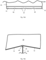
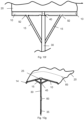
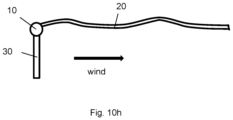
- the sail will move in response, blowing and extending outward providing shade to the user, as shown in Figs. 10g and 10h .
- the sail requires a wind speed of at least 2-3 miles per hour to flap or extend into the wind.
- the assembly has a reduced likelihood of falling over as a result heavy winds and/or when the wind shifts directions.
- the sail will self-adjust (e.g. the pivot cap, ribs, sail, support arm, and slider rotate about the non-movable mast in response to the wind blowing and changing direction).
- the sail rotates relative to the mast it prevents loosening the auger position and thereby causing failure of the assembly.
- the disclosed assembly therefore offers many advantages over prior art systems. For example, because the sail consistently blows in response to the wind, the user's views are not blocked as is common with prior art umbrellas. As a result, users can keep an eye on children and the water at all times.
- the disclosed assembly allows the wind to self-adjust the direction of ribs 10 and sail 20, saving the user the time and hassle of manually adjusting the assembly.
- the frame of the assembly (e.g. mast) does not catch the wind. If the mast falls over, it typically falls straight to the ground and does not tumble down the beach.
- the disclosed assembly is capable of being quickly assembled. Users can easily set up the umbrella assembly in about 40 seconds or less. Likewise, the assembly can be quickly and easily disassembled in about 40 seconds or less.
- Assembly 5 comprises a single mast, so it is universally permitted on beaches where tents are not.
- the mast is typically not in the middle of the umbrella sitting area, thereby providing adding convenience to the user.
- the disclosed assembly is quiet compared to other umbrellas and sun shades. Specifically, sail 20 does not loudly flap in the wind. Rather the sail stays extended by consistently floating in the direction of the wind.
- the disclosed system acts as an effective seagull deterrent. Because the sail is constantly changing directions in response to the wind, birds are deterred and tend to keep their distance.
Landscapes
- Engineering & Computer Science (AREA)
- Architecture (AREA)
- Civil Engineering (AREA)
- Structural Engineering (AREA)
- Wind Motors (AREA)
- Tents Or Canopies (AREA)
- Pivots And Pivotal Connections (AREA)
- Building Awnings And Sunshades (AREA)
Claims (15)
- Selbstjustierende Sonnenblendenbaugruppe (5), umfassend:ein Paar Rippen (10), die durch ein erstes Ende (11) und ein zweites Ende (12) definiert sind;ein Segel (20) mit einer Vorderkante (61), die einen Kanal (65) umfasst, der so bemessen und geformt ist, dass er jede Rippe aufnehmen kann, so dass sich die Rippen über die Vorderkante erstrecken;einen Mast (30), der ein erstes Ende (31) und ein zweites Ende (32) umfasst; undeinen Anker (35), der mit dem zweiten Ende des Masts funktionsfähig verbunden ist;dadurch gekennzeichnet, dass die selbstjustierende Sonnenblendenbaugruppe ferner umfasst:eine Schwenkkappe (40), an der das erste Ende jeder Rippe befestigt ist und mit der das erste Ende des Mastes funktionsfähig verbunden ist, wobei die Schwenkkappe so konfiguriert ist, dass sie sich im montierten Zustand frei um den Mast drehen kann;mindestens einen Stützarm (15) mit einem ersten Ende (16) und einem zweiten Ende (17), wobei das erste Ende des Stützarms an einer der Rippen befestigt ist und das zweite Ende des Stützarms an einem Schieber (45) befestigt ist, der so konfiguriert ist, dass er sich am Mast auf und ab bewegen kann; undeinem Spannungseinsteller (25), der die Drehung der Schwenkkappe um den Mast einstellt;wobei die Schwenkkappe, die Rippen, der Schieber und die Stützarme so konfiguriert sind, dass sie sich als Reaktion auf den Wind um den Mast drehen.
- Baugruppe nach Anspruch 1, wobei sich die Schwenkkappe um den Mast in einem Winkel von etwa 0 bis 360 Grad dreht.
- Baugruppe nach Anspruch 1, wobei die Rippen in einem Winkel von mehr als 180 Grad zueinander angeordnet sind.
- Baugruppe nach Anspruch 1, wobei eine Fläche der Schwenkkappe eine Verriegelung umfasst, die durch eine Brücke (94) definiert ist, die eine Öffnung (93) und einen verschiebbaren Arm (95) umfasst, der sich bewegt, um die Öffnung abzudecken und freizulegen.
- Baugruppe nach Anspruch 1, wobei der Schieber als Kragen konfiguriert ist, der um den Außenumfang des Mastes passt.
- Baugruppe nach Anspruch 1, wobei die Mastlänge einstellbar ist.
- Baugruppe nach Anspruch 1, wobei der Spannungseinsteller so konfiguriert ist, dass sich die Schwenkkappe, der Schieber, die Rippen und die Stützarme frei um den Mast drehen können, sich nicht um den Mast drehen können oder sich in einem beliebigen Grad dazwischen drehen können.
- Baugruppe nach Anspruch 1, wobei der Segelkanal eine oder mehrere Öffnungen (91) umfasst, um das Einsetzen der Rippen in den Kanal zu erleichtern.
- Baugruppe nach Anspruch 1, wobei der Segelkanal eine oder mehrere Öffnungen (92) umfasst, um einen direkten Kontakt zwischen jeder Rippe und einem entsprechenden Stützarm zu ermöglichen.
- Baugruppe nach Anspruch 1, wobei das Segel eine Oberseite (70) und eine Unterseite (71) aufweist und wobei die Unterseite mindestens einen Kanal (72) umfasst, der als ein Kanal mit einer offenen Mündung (73), die angrenzend an den Kanal positioniert ist, einem geschlossenen hinteren Ende (75) und einer Länge (74) parallel zur Länge des Segels konfiguriert ist.
- Verfahren zur Verwendung einer selbstjustierenden Sonnenblendenbaugruppe (5),
wobei die selbstjustierende Sonnenblendenbaugruppe umfasst:ein Paar Rippen (10), die durch ein erstes Ende (11) und ein zweites Ende (12) definiert sind;ein Segel (20) mit einer Vorderkante (61), die einen Kanal (65) umfasst, der so bemessen und geformt ist, dass er jede Rippe aufnehmen kann, so dass sich die Rippen über die Kante erstrecken;einen Mast (30), der ein erstes Ende (31) und ein zweites Ende (32) umfasst; undeinen Anker (35), der mit dem zweiten Ende des Mastes funktionsfähig verbunden ist;wobei das Verfahren umfasst:Positionieren des Ankers der selbstjustierenden Sonnenblendenbaugruppe in einer Auflagefläche;dadurch gekennzeichnet, dass die selbstjustierende Sonnenblendenbaugruppe ferner umfasst:eine Schwenkkappe (40), an der das erste Ende jeder Rippe befestigt ist und mit der das erste Ende des Mastes funktionsfähig verbunden ist, wobei die Schwenkkappe so konfiguriert ist, dass sie sich frei um den Mast drehen kann;mindestens einen Stützarm (15) mit einem ersten Ende (16) und einem zweiten Ende (17), wobei das erste Ende des Stützarms an einer der Rippen befestigt ist und das zweite Ende des Stützarms an einem Schieber (45) befestigt ist, der so konfiguriert ist, dass er sich am Mast auf und ab bewegen kann; undeinem Spannungseinsteller (25), der die Drehung der Schwenkkappe um den Mast einstellt;wobei das Verfahren ferner umfasst:Einstellen des Spannungseinstellers, um einen gewünschten Drehungsbetrag der Schwenkkappe, der Rippen, der Stützarme, des Schiebers und des Segels relativ zum nicht beweglichen Mast zu erreichen;wobei sich die Sonnenblendenbaugruppe als Reaktion auf den Wind selbst einstellt. - Verfahren nach Anspruch 11, wobei der Spannungseinsteller so konfiguriert ist, dass er so eingestellt werden kann, dass sich die Schwenkkappe, der Schieber, die Rippen und die Stützarme frei um den Mast drehen können, sich nicht um den Mast drehen können oder sich in einem beliebigen Grad dazwischen drehen können.
- Verfahren nach Anspruch 11, wobei das Segel eine Oberseite (70) und eine Unterseite (71) aufweist und wobei die Unterseite mindestens einen Kanal (72) umfasst, der als ein Kanal mit einer offenen Mündung (73), die angrenzend an den Kanal positioniert ist, einem geschlossenen hinteren Ende (75) und einer Länge (74) parallel zur Länge des Segels konfiguriert ist.
- Verfahren nach Anspruch 11, wobei eine Fläche der Schwenkkappe eine Verriegelung umfasst, die durch eine Brücke (94) definiert ist, die eine Öffnung (93) und einen verschiebbaren Arm (95) umfasst, der sich bewegt, um die Öffnung abzudecken und freizulegen.
- Verfahren nach Anspruch 11, wobei das Segel eine gegenüberliegende Hinterkante (62) aufweist, die einen angrenzenden Saum (82) umfasst, der aus einem haltbaren Material hergestellt ist.
Priority Applications (1)
| Application Number | Priority Date | Filing Date | Title |
|---|---|---|---|
| EP25179063.0A EP4585774A3 (de) | 2019-08-28 | 2020-06-22 | Selbsteinstellende sonnenschutzanordnung |
Applications Claiming Priority (2)
| Application Number | Priority Date | Filing Date | Title |
|---|---|---|---|
| US201962892700P | 2019-08-28 | 2019-08-28 | |
| PCT/US2020/038920 WO2021040863A1 (en) | 2019-08-28 | 2020-06-22 | Self-adjusting sun shade assembly |
Related Child Applications (1)
| Application Number | Title | Priority Date | Filing Date |
|---|---|---|---|
| EP25179063.0A Division EP4585774A3 (de) | 2019-08-28 | 2020-06-22 | Selbsteinstellende sonnenschutzanordnung |
Publications (4)
| Publication Number | Publication Date |
|---|---|
| EP4022155A1 EP4022155A1 (de) | 2022-07-06 |
| EP4022155A4 EP4022155A4 (de) | 2023-09-06 |
| EP4022155B1 true EP4022155B1 (de) | 2025-05-28 |
| EP4022155C0 EP4022155C0 (de) | 2025-05-28 |
Family
ID=74686010
Family Applications (2)
| Application Number | Title | Priority Date | Filing Date |
|---|---|---|---|
| EP25179063.0A Pending EP4585774A3 (de) | 2019-08-28 | 2020-06-22 | Selbsteinstellende sonnenschutzanordnung |
| EP20856803.0A Active EP4022155B1 (de) | 2019-08-28 | 2020-06-22 | Selbsteinstellende sonnenschutzbaugruppe |
Family Applications Before (1)
| Application Number | Title | Priority Date | Filing Date |
|---|---|---|---|
| EP25179063.0A Pending EP4585774A3 (de) | 2019-08-28 | 2020-06-22 | Selbsteinstellende sonnenschutzanordnung |
Country Status (7)
| Country | Link |
|---|---|
| US (2) | US11596211B2 (de) |
| EP (2) | EP4585774A3 (de) |
| JP (1) | JP7530667B2 (de) |
| CN (1) | CN114667382B (de) |
| AU (1) | AU2020340195B2 (de) |
| MX (2) | MX2022002359A (de) |
| WO (1) | WO2021040863A1 (de) |
Families Citing this family (18)
| Publication number | Priority date | Publication date | Assignee | Title |
|---|---|---|---|---|
| AU2021221687A1 (en) * | 2021-08-19 | 2023-03-09 | Mark Andrew Fraser | A portable shelter |
| US12256817B2 (en) | 2021-07-20 | 2025-03-25 | Mark Andrew Fraser | Portable shelter |
| AU2021218150A1 (en) * | 2021-08-19 | 2023-03-09 | Mark Andrew Fraser | A portable shelter |
| US20230235592A1 (en) * | 2022-01-25 | 2023-07-27 | James Michel | Airfoil beach shade |
| CN115189276A (zh) * | 2022-07-26 | 2022-10-14 | 国网福建省电力有限公司福州市长乐区供电公司 | 一种绝缘毯操作杆及其使用方法 |
| US12116797B2 (en) * | 2022-12-19 | 2024-10-15 | The Flying Nautilus, LLC | Portable shade system |
| US20240401366A1 (en) * | 2023-05-30 | 2024-12-05 | Solbello, Inc. | Sun shade assembly comprising improved noise dampening characteristics |
| US20250024923A1 (en) * | 2023-07-19 | 2025-01-23 | Talon James Roger SASEK | Sun shade |
| US20250067082A1 (en) * | 2023-08-23 | 2025-02-27 | Qinglin Cai | Portable Beach Sunshade Tent |
| USD1018755S1 (en) * | 2023-08-23 | 2024-03-19 | Qinglin Cai | Beach shade |
| USD1032766S1 (en) * | 2023-09-21 | 2024-06-25 | Qinglin Cai | Beach shade |
| JP1783862S (ja) * | 2023-09-21 | 2024-11-06 | ビーチキャノピー | |
| US12054961B2 (en) * | 2023-10-19 | 2024-08-06 | Xianrui Zeng | Beach sunshade |
| USD1097541S1 (en) * | 2024-03-15 | 2025-10-14 | Shaoxing Gaobu Tourism Products Co., Ltd. | Beach umbrella |
| USD1052680S1 (en) * | 2024-05-06 | 2024-11-26 | Qinglin Cai | Tent pole |
| USD1058739S1 (en) * | 2024-05-23 | 2025-01-21 | Wendi Xu | Parasol |
| USD1074906S1 (en) * | 2024-05-29 | 2025-05-13 | Xianrui Zeng | Beach tent |
| US12264491B1 (en) * | 2024-09-09 | 2025-04-01 | Xianrui Zeng | Beach sunshade canopy |
Family Cites Families (27)
| Publication number | Priority date | Publication date | Assignee | Title |
|---|---|---|---|---|
| US3075536A (en) * | 1959-12-09 | 1963-01-29 | George B D Parker | Beach tent |
| US3070107A (en) * | 1960-03-01 | 1962-12-25 | John W Beatty | Shelter apparatus |
| DE3043465C2 (de) * | 1980-11-18 | 1983-12-15 | Kortenbach & Rauh Kg, 5650 Solingen | Sonnenschirm |
| FR2684128A1 (fr) * | 1991-11-26 | 1993-05-28 | Marion Alain | Dispositif de protection contre le rayonnement solaire. |
| DE9310571U1 (de) * | 1993-07-15 | 1994-08-11 | Ledwoch, Thomas, 51149 Köln | Pflanzenschirm, insbesondere zum Schutz der Pflanzen vor zu starker Sonnenhitze |
| FR2717849A1 (fr) * | 1994-03-24 | 1995-09-29 | Mariat Jacques | Parasol à pied décentré et corolle pivotante. |
| US5555903A (en) * | 1995-02-06 | 1996-09-17 | Rizzotti; Salvatore A. | Aerodynamic umbrella |
| KR100285661B1 (ko) * | 1998-10-20 | 2001-04-02 | 이재윤 | 우산 |
| DE29920235U1 (de) * | 1999-11-17 | 2000-03-09 | Holly-Produkte-Vertriebs- und Lizenz GmbH, 88287 Grünkraut | Zusammenlegbare Sonnenschutzvorrichtung |
| WO2002011578A2 (en) * | 2000-08-10 | 2002-02-14 | Colin Garfield Page Taylor | Sun shade |
| AT6044U1 (de) * | 2002-03-12 | 2003-03-25 | Sensenwerk Sonnleithner Ges M | Fahnenmast |
| US7406977B1 (en) * | 2005-01-05 | 2008-08-05 | Shires Henry C | Lightweight shelter |
| US20060278261A1 (en) * | 2005-06-08 | 2006-12-14 | Fausto Marcelli | Sail umbrella |
| US20080196754A1 (en) | 2007-02-16 | 2008-08-21 | Manuel Saiz | Aerodynamic Sunshade |
| FR2951619B1 (fr) * | 2009-10-28 | 2013-03-01 | Adre X Evenement | Dispositif de protection contre la pluie et/ou les rayons du soleil |
| US20120291830A1 (en) * | 2011-05-02 | 2012-11-22 | Charles Crimi | Wind resistant canopy |
| US20130019794A1 (en) * | 2011-07-19 | 2013-01-24 | Terrell Neal | Corrosion-Resistant, Ultra-Strong, Universal Holder |
| US9051756B1 (en) * | 2011-10-18 | 2015-06-09 | John D. Jenkins | Collapsible sunshade |
| US20140041703A1 (en) * | 2012-08-10 | 2014-02-13 | Erik Laibe | Canopy device |
| WO2015009738A1 (en) * | 2013-07-15 | 2015-01-22 | The Coleman Company, Inc. | Adjustable free standing shelter |
| CN203626382U (zh) * | 2013-12-19 | 2014-06-04 | 中国通信建设第四工程局有限公司 | 一种通信应急帐篷支架 |
| DE202014103145U1 (de) * | 2014-07-09 | 2015-10-12 | alfa GmbH Fahnen- und Lichtmasten | Beleuchtung für einen Fahnenmast und Energiezuführungsvorrichtung |
| US10099751B1 (en) * | 2017-07-21 | 2018-10-16 | Lawrence A Greer | Recreational canopy |
| CN109419115A (zh) * | 2017-08-27 | 2019-03-05 | 南京乐朋电子科技有限公司 | 一种智能悬停遮阳伞 |
| WO2019055608A1 (en) * | 2017-09-14 | 2019-03-21 | Lso, Lp | PARASOL WING |
| CN108476807B (zh) * | 2018-01-19 | 2024-04-26 | 华北水利水电大学 | 兼具支撑与灌溉的多功能农用大棚及其搭建方法 |
| HU5705U (hu) * | 2023-07-18 | 2024-03-28 | Toth Peter Dr | Árnyékoló szerkezet árbócrögzítési ponttal rendelkezõ SUP deszkához |
-
2020
- 2020-06-22 JP JP2022512758A patent/JP7530667B2/ja active Active
- 2020-06-22 EP EP25179063.0A patent/EP4585774A3/de active Pending
- 2020-06-22 US US17/417,739 patent/US11596211B2/en not_active Ceased
- 2020-06-22 CN CN202080060562.9A patent/CN114667382B/zh active Active
- 2020-06-22 US US18/367,224 patent/USRE50606E1/en active Active
- 2020-06-22 AU AU2020340195A patent/AU2020340195B2/en active Active
- 2020-06-22 WO PCT/US2020/038920 patent/WO2021040863A1/en not_active Ceased
- 2020-06-22 EP EP20856803.0A patent/EP4022155B1/de active Active
- 2020-06-22 MX MX2022002359A patent/MX2022002359A/es unknown
-
2022
- 2022-02-24 MX MX2025014837A patent/MX2025014837A/es unknown
Also Published As
| Publication number | Publication date |
|---|---|
| AU2020340195B2 (en) | 2025-11-20 |
| EP4022155A1 (de) | 2022-07-06 |
| MX2025014837A (es) | 2026-01-07 |
| AU2020340195A1 (en) | 2022-02-24 |
| WO2021040863A1 (en) | 2021-03-04 |
| JP7530667B2 (ja) | 2024-08-08 |
| US11596211B2 (en) | 2023-03-07 |
| US20220175098A1 (en) | 2022-06-09 |
| USRE50606E1 (en) | 2025-09-30 |
| CN114667382A (zh) | 2022-06-24 |
| EP4022155C0 (de) | 2025-05-28 |
| EP4585774A3 (de) | 2025-12-10 |
| MX2022002359A (es) | 2022-04-06 |
| EP4022155A4 (de) | 2023-09-06 |
| CN114667382B (zh) | 2024-11-26 |
| EP4585774A2 (de) | 2025-07-16 |
| JP2022546366A (ja) | 2022-11-04 |
Similar Documents
| Publication | Publication Date | Title |
|---|---|---|
| EP4022155B1 (de) | Selbsteinstellende sonnenschutzbaugruppe | |
| EP1097652B1 (de) | Freiarmschirm | |
| US10492579B1 (en) | Arthritic-aiding triple-sail wind-rotating wind-aligning umbrella | |
| US7493909B2 (en) | Umbrella assembly with tilt adjustment | |
| US9289038B2 (en) | Cantilever umbrella | |
| US7918236B2 (en) | Portable sun and weather shelter | |
| US20080202570A1 (en) | Hub assembly for an umbrella frame | |
| US10655357B1 (en) | Convertible hammock-shade tent | |
| AU2019329384B2 (en) | Multi-angle multi-function umbrella | |
| EP2491205B1 (de) | Zusammenklapp- und tragbarer schutzraum | |
| US20090145471A1 (en) | Portable tent | |
| US11096458B1 (en) | Multi-use umbrella with water filtration and sail functions | |
| US10161158B2 (en) | Combination umbrella and cover | |
| US7779849B2 (en) | Umbrella featuring a vertically deployable sun shade | |
| CA3272470A1 (en) | SHADE AWNING TENSIONING KIT | |
| US20060070644A1 (en) | Side supported umbrella | |
| EP1700536B1 (de) | Standschirm mit Neigungsjustierung | |
| DE10129578C1 (de) | Zweiteiliger Schirm | |
| KR102955065B1 (ko) | 접이식 파라솔 | |
| HUP0600684A2 (en) | Umbrella for sheltering from rain and sunlight | |
| JPS6249042B2 (de) | ||
| EP2159350A1 (de) | Zusammenklappbarer Schutzraum | |
| HK1095493A (en) | Umbrella assembly with tilt adjustment | |
| DE19855105A1 (de) | Sonnenschutzschirm, windstabil | |
| JPH05149034A (ja) | 形状が変化する日除けテント |
Legal Events
| Date | Code | Title | Description |
|---|---|---|---|
| STAA | Information on the status of an ep patent application or granted ep patent |
Free format text: STATUS: THE INTERNATIONAL PUBLICATION HAS BEEN MADE |
|
| PUAI | Public reference made under article 153(3) epc to a published international application that has entered the european phase |
Free format text: ORIGINAL CODE: 0009012 |
|
| STAA | Information on the status of an ep patent application or granted ep patent |
Free format text: STATUS: REQUEST FOR EXAMINATION WAS MADE |
|
| 17P | Request for examination filed |
Effective date: 20220228 |
|
| AK | Designated contracting states |
Kind code of ref document: A1 Designated state(s): AL AT BE BG CH CY CZ DE DK EE ES FI FR GB GR HR HU IE IS IT LI LT LU LV MC MK MT NL NO PL PT RO RS SE SI SK SM TR |
|
| DAV | Request for validation of the european patent (deleted) | ||
| DAX | Request for extension of the european patent (deleted) | ||
| A4 | Supplementary search report drawn up and despatched |
Effective date: 20230803 |
|
| RIC1 | Information provided on ipc code assigned before grant |
Ipc: E04H 15/00 20060101ALI20230728BHEP Ipc: E04H 15/58 20060101ALI20230728BHEP Ipc: A45B 23/00 20060101ALI20230728BHEP Ipc: E04H 12/22 20060101ALI20230728BHEP Ipc: E04H 15/28 20060101AFI20230728BHEP |
|
| GRAP | Despatch of communication of intention to grant a patent |
Free format text: ORIGINAL CODE: EPIDOSNIGR1 |
|
| STAA | Information on the status of an ep patent application or granted ep patent |
Free format text: STATUS: GRANT OF PATENT IS INTENDED |
|
| INTG | Intention to grant announced |
Effective date: 20250203 |
|
| GRAS | Grant fee paid |
Free format text: ORIGINAL CODE: EPIDOSNIGR3 |
|
| GRAA | (expected) grant |
Free format text: ORIGINAL CODE: 0009210 |
|
| STAA | Information on the status of an ep patent application or granted ep patent |
Free format text: STATUS: THE PATENT HAS BEEN GRANTED |
|
| AK | Designated contracting states |
Kind code of ref document: B1 Designated state(s): AL AT BE BG CH CY CZ DE DK EE ES FI FR GB GR HR HU IE IS IT LI LT LU LV MC MK MT NL NO PL PT RO RS SE SI SK SM TR |
|
| REG | Reference to a national code |
Ref country code: GB Ref legal event code: FG4D |
|
| REG | Reference to a national code |
Ref country code: CH Ref legal event code: EP |
|
| REG | Reference to a national code |
Ref country code: IE Ref legal event code: FG4D Ref country code: DE Ref legal event code: R096 Ref document number: 602020052087 Country of ref document: DE |
|
| U01 | Request for unitary effect filed |
Effective date: 20250613 |
|
| U07 | Unitary effect registered |
Designated state(s): AT BE BG DE DK EE FI FR IT LT LU LV MT NL PT RO SE SI Effective date: 20250627 |
|
| PG25 | Lapsed in a contracting state [announced via postgrant information from national office to epo] |
Ref country code: ES Free format text: LAPSE BECAUSE OF FAILURE TO SUBMIT A TRANSLATION OF THE DESCRIPTION OR TO PAY THE FEE WITHIN THE PRESCRIBED TIME-LIMIT Effective date: 20250528 |
|
| PG25 | Lapsed in a contracting state [announced via postgrant information from national office to epo] |
Ref country code: GR Free format text: LAPSE BECAUSE OF FAILURE TO SUBMIT A TRANSLATION OF THE DESCRIPTION OR TO PAY THE FEE WITHIN THE PRESCRIBED TIME-LIMIT Effective date: 20250829 Ref country code: NO Free format text: LAPSE BECAUSE OF FAILURE TO SUBMIT A TRANSLATION OF THE DESCRIPTION OR TO PAY THE FEE WITHIN THE PRESCRIBED TIME-LIMIT Effective date: 20250828 |
|
| PG25 | Lapsed in a contracting state [announced via postgrant information from national office to epo] |
Ref country code: PL Free format text: LAPSE BECAUSE OF FAILURE TO SUBMIT A TRANSLATION OF THE DESCRIPTION OR TO PAY THE FEE WITHIN THE PRESCRIBED TIME-LIMIT Effective date: 20250528 |
|
| PG25 | Lapsed in a contracting state [announced via postgrant information from national office to epo] |
Ref country code: HR Free format text: LAPSE BECAUSE OF FAILURE TO SUBMIT A TRANSLATION OF THE DESCRIPTION OR TO PAY THE FEE WITHIN THE PRESCRIBED TIME-LIMIT Effective date: 20250528 |
|
| PG25 | Lapsed in a contracting state [announced via postgrant information from national office to epo] |
Ref country code: RS Free format text: LAPSE BECAUSE OF FAILURE TO SUBMIT A TRANSLATION OF THE DESCRIPTION OR TO PAY THE FEE WITHIN THE PRESCRIBED TIME-LIMIT Effective date: 20250828 |
|
| PG25 | Lapsed in a contracting state [announced via postgrant information from national office to epo] |
Ref country code: IS Free format text: LAPSE BECAUSE OF FAILURE TO SUBMIT A TRANSLATION OF THE DESCRIPTION OR TO PAY THE FEE WITHIN THE PRESCRIBED TIME-LIMIT Effective date: 20250928 |
|
| U20 | Renewal fee for the european patent with unitary effect paid |
Year of fee payment: 6 Effective date: 20250923 |
|
| PG25 | Lapsed in a contracting state [announced via postgrant information from national office to epo] |
Ref country code: SM Free format text: LAPSE BECAUSE OF FAILURE TO SUBMIT A TRANSLATION OF THE DESCRIPTION OR TO PAY THE FEE WITHIN THE PRESCRIBED TIME-LIMIT Effective date: 20250528 |
|
| PG25 | Lapsed in a contracting state [announced via postgrant information from national office to epo] |
Ref country code: CZ Free format text: LAPSE BECAUSE OF FAILURE TO SUBMIT A TRANSLATION OF THE DESCRIPTION OR TO PAY THE FEE WITHIN THE PRESCRIBED TIME-LIMIT Effective date: 20250528 |
|
| PG25 | Lapsed in a contracting state [announced via postgrant information from national office to epo] |
Ref country code: SK Free format text: LAPSE BECAUSE OF FAILURE TO SUBMIT A TRANSLATION OF THE DESCRIPTION OR TO PAY THE FEE WITHIN THE PRESCRIBED TIME-LIMIT Effective date: 20250528 |
|
| REG | Reference to a national code |
Ref country code: CH Ref legal event code: H13 Free format text: ST27 STATUS EVENT CODE: U-0-0-H10-H13 (AS PROVIDED BY THE NATIONAL OFFICE) Effective date: 20260127 |
|
| PG25 | Lapsed in a contracting state [announced via postgrant information from national office to epo] |
Ref country code: MC Free format text: LAPSE BECAUSE OF FAILURE TO SUBMIT A TRANSLATION OF THE DESCRIPTION OR TO PAY THE FEE WITHIN THE PRESCRIBED TIME-LIMIT Effective date: 20250528 |
|
| PLBE | No opposition filed within time limit |
Free format text: ORIGINAL CODE: 0009261 |
|
| STAA | Information on the status of an ep patent application or granted ep patent |
Free format text: STATUS: NO OPPOSITION FILED WITHIN TIME LIMIT |
|
| REG | Reference to a national code |
Ref country code: CH Ref legal event code: L10 Free format text: ST27 STATUS EVENT CODE: U-0-0-L10-L00 (AS PROVIDED BY THE NATIONAL OFFICE) Effective date: 20260409 |
|
| PG25 | Lapsed in a contracting state [announced via postgrant information from national office to epo] |
Ref country code: IE Free format text: LAPSE BECAUSE OF NON-PAYMENT OF DUE FEES Effective date: 20250622 |