EP4019893B1 - Utensil zur auswertung von längenmessfehlern in einer röntgen-ct-vorrichtung zur dreidimensionalen formmessung - Google Patents
Utensil zur auswertung von längenmessfehlern in einer röntgen-ct-vorrichtung zur dreidimensionalen formmessung Download PDFInfo
- Publication number
- EP4019893B1 EP4019893B1 EP22156521.1A EP22156521A EP4019893B1 EP 4019893 B1 EP4019893 B1 EP 4019893B1 EP 22156521 A EP22156521 A EP 22156521A EP 4019893 B1 EP4019893 B1 EP 4019893B1
- Authority
- EP
- European Patent Office
- Prior art keywords
- spheres
- ray
- axis
- utensil
- sphere
- Prior art date
- Legal status (The legal status is an assumption and is not a legal conclusion. Google has not performed a legal analysis and makes no representation as to the accuracy of the status listed.)
- Active
Links
Images


Classifications
-
- G—PHYSICS
- G01—MEASURING; TESTING
- G01B—MEASURING LENGTH, THICKNESS OR SIMILAR LINEAR DIMENSIONS; MEASURING ANGLES; MEASURING AREAS; MEASURING IRREGULARITIES OF SURFACES OR CONTOURS
- G01B15/00—Measuring arrangements characterised by the use of electromagnetic waves or particle radiation, e.g. by the use of microwaves, X-rays, gamma rays or electrons
- G01B15/04—Measuring arrangements characterised by the use of electromagnetic waves or particle radiation, e.g. by the use of microwaves, X-rays, gamma rays or electrons for measuring contours or curvatures
- G01B15/045—Measuring arrangements characterised by the use of electromagnetic waves or particle radiation, e.g. by the use of microwaves, X-rays, gamma rays or electrons for measuring contours or curvatures by measuring absorption
-
- G—PHYSICS
- G01—MEASURING; TESTING
- G01B—MEASURING LENGTH, THICKNESS OR SIMILAR LINEAR DIMENSIONS; MEASURING ANGLES; MEASURING AREAS; MEASURING IRREGULARITIES OF SURFACES OR CONTOURS
- G01B15/00—Measuring arrangements characterised by the use of electromagnetic waves or particle radiation, e.g. by the use of microwaves, X-rays, gamma rays or electrons
- G01B15/04—Measuring arrangements characterised by the use of electromagnetic waves or particle radiation, e.g. by the use of microwaves, X-rays, gamma rays or electrons for measuring contours or curvatures
-
- A—HUMAN NECESSITIES
- A61—MEDICAL OR VETERINARY SCIENCE; HYGIENE
- A61B—DIAGNOSIS; SURGERY; IDENTIFICATION
- A61B6/00—Apparatus or devices for radiation diagnosis; Apparatus or devices for radiation diagnosis combined with radiation therapy equipment
- A61B6/02—Arrangements for diagnosis sequentially in different planes; Stereoscopic radiation diagnosis
- A61B6/03—Computed tomography [CT]
- A61B6/032—Transmission computed tomography [CT]
-
- A—HUMAN NECESSITIES
- A61—MEDICAL OR VETERINARY SCIENCE; HYGIENE
- A61B—DIAGNOSIS; SURGERY; IDENTIFICATION
- A61B6/00—Apparatus or devices for radiation diagnosis; Apparatus or devices for radiation diagnosis combined with radiation therapy equipment
- A61B6/58—Testing, adjusting or calibrating thereof
- A61B6/582—Calibration
- A61B6/583—Calibration using calibration phantoms
-
- A—HUMAN NECESSITIES
- A61—MEDICAL OR VETERINARY SCIENCE; HYGIENE
- A61B—DIAGNOSIS; SURGERY; IDENTIFICATION
- A61B90/00—Instruments, implements or accessories specially adapted for surgery or diagnosis and not covered by any of the groups A61B1/00 - A61B50/00, e.g. for luxation treatment or for protecting wound edges
- A61B90/06—Measuring instruments not otherwise provided for
-
- G—PHYSICS
- G01—MEASURING; TESTING
- G01B—MEASURING LENGTH, THICKNESS OR SIMILAR LINEAR DIMENSIONS; MEASURING ANGLES; MEASURING AREAS; MEASURING IRREGULARITIES OF SURFACES OR CONTOURS
- G01B21/00—Measuring arrangements or details thereof, where the measuring technique is not covered by the other groups of this subclass, unspecified or not relevant
- G01B21/02—Measuring arrangements or details thereof, where the measuring technique is not covered by the other groups of this subclass, unspecified or not relevant for measuring length, width, or thickness
- G01B21/04—Measuring arrangements or details thereof, where the measuring technique is not covered by the other groups of this subclass, unspecified or not relevant for measuring length, width, or thickness by measuring coordinates of points
- G01B21/042—Calibration or calibration artifacts
-
- G—PHYSICS
- G01—MEASURING; TESTING
- G01N—INVESTIGATING OR ANALYSING MATERIALS BY DETERMINING THEIR CHEMICAL OR PHYSICAL PROPERTIES
- G01N23/00—Investigating or analysing materials by the use of wave or particle radiation, e.g. X-rays or neutrons, not covered by groups G01N3/00 – G01N17/00, G01N21/00 or G01N22/00
- G01N23/02—Investigating or analysing materials by the use of wave or particle radiation, e.g. X-rays or neutrons, not covered by groups G01N3/00 – G01N17/00, G01N21/00 or G01N22/00 by transmitting the radiation through the material
- G01N23/04—Investigating or analysing materials by the use of wave or particle radiation, e.g. X-rays or neutrons, not covered by groups G01N3/00 – G01N17/00, G01N21/00 or G01N22/00 by transmitting the radiation through the material and forming images of the material
- G01N23/046—Investigating or analysing materials by the use of wave or particle radiation, e.g. X-rays or neutrons, not covered by groups G01N3/00 – G01N17/00, G01N21/00 or G01N22/00 by transmitting the radiation through the material and forming images of the material using tomography, e.g. computed tomography [CT]
-
- A—HUMAN NECESSITIES
- A61—MEDICAL OR VETERINARY SCIENCE; HYGIENE
- A61B—DIAGNOSIS; SURGERY; IDENTIFICATION
- A61B90/00—Instruments, implements or accessories specially adapted for surgery or diagnosis and not covered by any of the groups A61B1/00 - A61B50/00, e.g. for luxation treatment or for protecting wound edges
- A61B90/06—Measuring instruments not otherwise provided for
- A61B2090/061—Measuring instruments not otherwise provided for for measuring dimensions, e.g. length
-
- A—HUMAN NECESSITIES
- A61—MEDICAL OR VETERINARY SCIENCE; HYGIENE
- A61B—DIAGNOSIS; SURGERY; IDENTIFICATION
- A61B6/00—Apparatus or devices for radiation diagnosis; Apparatus or devices for radiation diagnosis combined with radiation therapy equipment
- A61B6/52—Devices using data or image processing specially adapted for radiation diagnosis
- A61B6/5205—Devices using data or image processing specially adapted for radiation diagnosis involving processing of raw data to produce diagnostic data
-
- A—HUMAN NECESSITIES
- A61—MEDICAL OR VETERINARY SCIENCE; HYGIENE
- A61B—DIAGNOSIS; SURGERY; IDENTIFICATION
- A61B6/00—Apparatus or devices for radiation diagnosis; Apparatus or devices for radiation diagnosis combined with radiation therapy equipment
- A61B6/54—Control of apparatus or devices for radiation diagnosis
-
- G—PHYSICS
- G01—MEASURING; TESTING
- G01N—INVESTIGATING OR ANALYSING MATERIALS BY DETERMINING THEIR CHEMICAL OR PHYSICAL PROPERTIES
- G01N2223/00—Investigating materials by wave or particle radiation
- G01N2223/10—Different kinds of radiation or particles
- G01N2223/101—Different kinds of radiation or particles electromagnetic radiation
- G01N2223/1016—X-ray
-
- G—PHYSICS
- G01—MEASURING; TESTING
- G01N—INVESTIGATING OR ANALYSING MATERIALS BY DETERMINING THEIR CHEMICAL OR PHYSICAL PROPERTIES
- G01N2223/00—Investigating materials by wave or particle radiation
- G01N2223/30—Accessories, mechanical or electrical features
- G01N2223/303—Accessories, mechanical or electrical features calibrating, standardising
-
- G—PHYSICS
- G01—MEASURING; TESTING
- G01N—INVESTIGATING OR ANALYSING MATERIALS BY DETERMINING THEIR CHEMICAL OR PHYSICAL PROPERTIES
- G01N2223/00—Investigating materials by wave or particle radiation
- G01N2223/30—Accessories, mechanical or electrical features
- G01N2223/33—Accessories, mechanical or electrical features scanning, i.e. relative motion for measurement of successive object-parts
- G01N2223/3306—Accessories, mechanical or electrical features scanning, i.e. relative motion for measurement of successive object-parts object rotates
-
- G—PHYSICS
- G01—MEASURING; TESTING
- G01N—INVESTIGATING OR ANALYSING MATERIALS BY DETERMINING THEIR CHEMICAL OR PHYSICAL PROPERTIES
- G01N2223/00—Investigating materials by wave or particle radiation
- G01N2223/40—Imaging
- G01N2223/419—Imaging computed tomograph
-
- G—PHYSICS
- G01—MEASURING; TESTING
- G01N—INVESTIGATING OR ANALYSING MATERIALS BY DETERMINING THEIR CHEMICAL OR PHYSICAL PROPERTIES
- G01N2223/00—Investigating materials by wave or particle radiation
- G01N2223/60—Specific applications or type of materials
- G01N2223/645—Specific applications or type of materials quality control
Definitions
- the present invention relates to a utensil for evaluating a length measurement error in an X-ray CT device for three-dimensional shape measurement designed to measure the dimensions of a test object.
- a utensil for evaluating a length measurement error in an X-ray CT device for three-dimensional shape measurement (hereinafter referred to as a utensil) corresponding to VDI/VDE2630-1.3
- a utensil made by Cael Zeiss Inc. is known (see Non-Patent Literature 1).
- Non-Patent Literature 1 is one of a type referred to as a forest gauge.
- spheres are arranged in a space by installing upright support rods supporting the spheres on a stepwise base.
- One having 27 spheres and one having 22 spheres as the number of spheres are known.
- Patent Literature 1 proposes a calibrator of an X-ray CT device, which intends to accurately calibrate the dimensions of shapes including the internal shape of a test object from projection images obtained by the X-ray CT device.
- spheres are arranged in a space by firmly fixing the spheres on the outer circumference of a cylindrical body.
- the coordinates of the respective spheres are measured by CMM (coordinate measuring machine: contact type three-dimensional coordinate measuring machine) or the like.
- CMM coordinate measuring machine: contact type three-dimensional coordinate measuring machine
- a length measurement error by X-ray CT is evaluated.
- DE102014113977 (A1 ) is directed at a method for determining at least one parameter that describes the geometry of a measuring arrangement in the form of a computer tomography sensor system, at least consisting of a radiation source, a flat detector and a mechanical axis of rotation for rotating the workpiece or for rotating the radiation source and detector.
- the calibrator described in Patent Literature 1 has the problem of being able to evaluate only a cylindrical region in an imaging space because no sphere can be arranged in the cavity inside the cylindrical body.
- the forest gauge it is possible to arrange spheres on the central axis; however, there is the following problem.
- Fig. 15 is a schematic diagram illustrating an evaluation range in an imaging visual space when performing X-ray CT imaging on a conventional forest gauge.
- Fig. 15 illustrates the case where the 27-sphere forest gauge made by Carl Zeiss, Inc. is targeted for the X-ray CT imaging.
- the imaging visual space of a cylindrical shape is indicated by virtual lines
- Fig. 15(b) an evaluation range at one time of X-ray CT imaging is illustrated.
- Fig. 15(c) schematically illustrates evaluation ranges and unevaluable ranges in the imaging visual space when the X-ray CT imaging was performed three times at switched Z positions
- Fig. 15(d) is a diagram illustrating the mutual positional relationship among three conical spaces in the imaging visual space when the X-ray CT imaging was performed three times at the switched Z positions.
- a length reference in the X axial direction and a length reference in the Y axial direction are different, and for example, a perfect circle is deformed into an ellipse on a cross-sectional image orthogonal to the Z axis.
- the length reference in the X axial direction and the length reference in the Y axial direction are gradually changed depending on the position of the Z axis, and thereby for example, a cylindrical shape is deformed into a truncated conical shape.
- local deformation occurs around a specific point.
- the X-Y plane is gradually rotated and twist-like deformation occurs in the space.
- the Z axis is aligned only with the sphere at the apex of the conical space, and therefore the mutual positional relationship among conical spaces each serving as an evaluation target at one time of X-ray CT imaging among multiple times of repeated X-ray CT imaging cannot be evaluated. Accordingly, as illustrated in Fig. 15(d) , the deformation of the conical spaces can be captured, but the mutual positional relationship of a conical space at each time of X-ray CT imaging cannot be captured.
- the present invention has been made in order to solve the above-described problems, and a first object is to provide a utensil for evaluating a length measurement error in an X-ray CT device for three-dimensional shape measurement, which makes it possible to sufficiently capture spatial distortion specific to the X-ray CT device and evaluate the three-dimensional shape measurement accuracy of the X-ray CT device.
- Fig. 16 is a schematic diagram illustrating conventional methods for fixing a support rod supporting a sphere to a base.
- a method for fixing the support rods a method referred to as so-called split clamping has been employed.
- a fixing member 140 formed with a hole insertable with a support rod 136 is attached to a base 131 by screwing, and by operating a clamping screw 145 to narrow a clearance 144 in a split part, clamping force is given to the support rod 136 to fix the support rod 136 to the base 131.
- a fixing member 140 formed with a hole insertable with a support rod 136 is attached to a base 131 by screwing, and by operating a clamping screw 145 to narrow a clearance 144 in a split part, clamping force is given to the support rod 136 to fix the support rod 136 to the base 131.
- a clamping screw 145 to narrow a clearance 144 in a split part
- a tenth example is such that in the utensil for evaluating a length measurement error in an X-ray CT device for three-dimensional shape measurement according to the ninth example, the multiple X-Y planes are at least three X-Y planes whose mutual distances in a Z direction are equally separated, and among the multiple spheres, multiple sets of two spheres oppositely arranged with respect to the Z axis are arranged, and thereby spheres arranged in each of the three X-Y planes are equally arranged at intervals of substantially 30 degrees on a circle around the Z axis in a plan view where the three X-Y planes are superposed.
- the ninth example since as the arrangement of the outer circumference side spheres, at least four spheres are arranged separated from the Z axis by a predetermined distance in each of the multiple X-Y planes having different Z positions, a conventional structure where spheres are arranged on conical surfaces is not formed, and therefore spatial distortion specific to an X-ray CT device can be sufficiently captured. Accordingly, the three-dimensional shape measurement accuracy of the X-ray CT device can be evaluated.
- the top of the base as a flat surface and differentiating the lengths of the multiple support rods, the arrangement of the spheres having different Z positions is achieved, the shadow of a step appearing when a base is formed stepwise as conventional is not imaged, and a range evaluable at one time of imaging is widened, thus making it possible to reduce the number of times of performing repeated measurement with a Z axis position changed than before.
- each support rod can be constrained in the three-dimensional space by the support rod holding mechanism, a utensil that even when a significant amount of stress is applied to a sphere or a support rod, or even when turned upside-down during transportation or installation, prevents a change in sphere position can be fabricated.
- the tip supporting a sphere is shaped as the conical concave part, the sphere comes into line contact with the conical tilt surface of the conical concave part, and individual differences among spheres can be made less influential to uniform the positional relationships between spheres and corresponding support rods.
- the X-ray irradiation part 11 is provided inside with an X-ray tube as an X-ray source, and from the X-ray tube, generates X-rays corresponding to tube voltage and tube current supplied from a high voltage generator 15.
- the high voltage generator 15 is controlled by an X-ray control part 16, and the X-ray control part 16 is connected to a personal computer PC installed with control software for controlling the whole of the X-ray CT device.
- the X-ray detector 12 is one in which an image intensifier (I.I.) is combined with a CCD camera, or an FPD (Flat Panel Detector), and connected to the personal computer PC via a CT image reconstruction arithmetic unit 18.
- the X-ray detector 12 is configured to be separable/approachable with respect to the rotation stage 13 in order to scale a fluoroscopic imaging region. Further, the rotation stage 13 is also separable/approachable with respect to the X-ray irradiation part 11.
- the rotation stage 13 is adapted to rotate with a Z-axis orthogonal to an X-axis along an X-ray light axis L connecting from the X-ray irradiation part 11 to the X-ray detector 12 as a rotation axis R, and also be movable in the horizontal direction corresponding to XY directions and the vertical direction corresponding to a Z direction by a stage driving mechanism 14.
- the stage driving mechanism 14 is connected to the personal computer PC via a stage control part 17.
- the CT image reconstruction arithmetic unit 18 includes a computer including: a ROM, RAM, hard disk, and the like as storage devices for storing programs, detection data from the X-ray detector 12, and the like; and a CPU as an arithmetic unit.
- the retrieved X-ray transmission data covering the 360 degrees is used to construct a tomographic image (CT image) of the test object, which is sliced along a plane parallel with the X-Y plane.
- CT image is transmitted from the CT image reconstruction arithmetic unit 18 to the personal computer PC, and used for three-dimensional imaging by a three-dimensional image construction program installed in the personal computer PC.
- the personal computer PC is connected with a display device 23 such as a liquid crystal display and input devices 22 including a keyboard 22a and a mouse 22b.
- the keyboard 22a and the mouse 22b are ones for providing inputs by an operator in various operations.
- the display device 23 displays a CT image transmitted from the CT image reconstruction arithmetic unit 18 to the personal computer PC, as well as displays a three-dimensional image constructed using the CT image.
- the functions of the CT image reconstruction arithmetic unit 18 may be integrated with the personal computer PC and implemented as computer's peripheral devices and software by one computer.
- the X-ray CT device obtains volume data referred to as a reconstruction image from multiple projection images detected by the X-ray detector 12, and therefore when evaluated as one for three-dimensional shape measurement, is required to be able to confirm length measurement accuracy over a wide range relative to the X-ray detection region of the X-ray detector 12.
- the X-ray CT device changes the positional relationship among the X-ray source, the rotation stage 13, and the X-ray detector 12 in order to change the magnification ratio of a projection image, and is therefore required to be able to evaluate a geometric error due to displacement from a state where respective components are ideally assembled. Further, the X-ray CT device performs X-ray imaging with the rotation stage 13 rotated, and is therefore also required to be able to evaluate the motion error of the rotation stage 13.
- Fig. 2 is a perspective view of the utensil 30 for evaluating a length measurement error in the X-ray CT device for three-dimensional shape measurement according to the present invention.
- the utensil 30 for evaluating a length measurement error in the X-ray CT device for three-dimensional measurement (hereinafter referred to as a utensil 30) is such that support rods 36, 37, 38 whose tips are fixed with spheres 35 and whose lengths are different are attached to a base 31, and thereby 15 spheres 35 are arranged in an XYZ space on the base 31.
- the support rods 36, 37, 38 supporting the spheres 35 and having different lengths are installed upright at predetermined intervals.
- the base 31 is formed of a low thermal expansion metallic material whose thermal deformation is extremely small.
- the spheres 35 spherical bodies whose shape error is small (sphericity is high) are employed, and for the support rods 36, 37, 38, a material such as ceramic is employed.
- the arrangement space of the sphere 35 on the top of the base 31 is adapted to be covered with a cylindrical cover 33 at the time of storage and at the time of use so as to prevent the spatial arrangement of the respective spheres 35 after coordinate measurement by CMM from being disordered.
- the cover 33 is formed of a material having relatively high X-ray transmittance, such as an acrylic resin.
- the cover 33 is not required to be transparent to visible light, but is desirably transparent to visible light. When it is transparent, an operator can directly view the inside, and therefore structural understanding can be facilitated.
- the support rods 37 has a dimension longer than the support rods 36 by 30 mm
- the support rods 38 has a dimension longer than the support rods 37 by 30 mm.
- the intervals between the three Z positions are equalized.
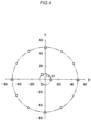
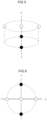
- Fig. 3 and Fig. 4 are schematic diagrams illustrating the arrangement of the spheres 35.
- Fig. 3 is a three-dimensional image illustrating the arrangement of the respective spheres 35 in a cylindrical imaging space indicated by dashed-two dotted lines
- Fig. 4 is a schematic plan view.
- projection coordinates (Xi, Yi) obtained by projecting the positions of the respective spheres 35 parallel to the Z axis toward the X-Y plane at the Z position of the spheres 35 supported by the shortest support rods 36 are illustrated.
- triangles ( ⁇ ) in the view represent the positions of the five spheres 35 supported by the shortest support rods 36
- quadrangles ( ⁇ ) represent the positions of the five spheres 35 supported by the intermediate-length support rods 37
- circles ( ⁇ ) represent the positions of the five spheres 35 supported by the longest support rods 38.
- the arrangement of the four spheres 35 is made substantially cross-shaped, in which the four spheres 35 are displaced from each other by approximately 90 degrees.
- the positional relationship among the respective spheres 35 arranged on the outer circle is such that in the plan view as illustrated in Fig. 4 , the spheres 35 are arranged on the same circle around the Z axis at regular intervals. That is, positions on the circle around the origin (0, 0) in Fig. 4 are positions separated from each other by substantially 30 degrees.
- the spheres 35 are spirally arranged at every 90 degrees in the order of the triangle ( ⁇ ), the quadrangle ( ⁇ ), and the circle ( ⁇ ) on the basis of the combination of the 30-degree rotation with the Z axis as a rotation axis and the 30-mm translation parallel to the Z axis.
- the multiple outer circumference side spheres arranged in the respective three X-Y planes are cylindrically arranged as evaluation points in the cylindrically-shaped region (indicated by the dashed-two dotted lines) of the imaging space.
- a guide for the vicinity of the Z axis is a distance range where a distance from the Z axis is approximately 20 % or less of the diameter of the circle defining the arrangement positions of four spheres 35 in each of the X-Y planes.
- the three spheres 35 respectively supported by the support rods 36, 37, 38 having different lengths are arranged on the inner circumferential circle at equal intervals; however, as long as three sphere positions having different heights along the Z axis can be obtained, they are not required to be arranged on the same circle.
- the spheres 35 can be projected to positions near the maximum longitudinal X-ray detection region of the X-ray detector 12 and to different height positions. For this reason, when performing imaging multiple times with a Z position changed, the inside of the cylindrical imaging visual space can be evaluated by a small number of imaging times without creating an unevaluable range between single imaging spaces. Further, by arranging two spheres 35 in each of the X-Y planes having different Z positions, the evaluation of the motion error of the rotation stage 13 and the evaluation of a geometric error can be performed.
- outer circumference of the outer circumference side spheres in the present invention refers to a circumference such as a circle having a diameter or an ellipse having the major axis, which enables the spheres 35 to be projected to positions near the maximum lateral X-ray detection region of the X-ray detector 12.
- the outer circumference side spheres in the present invention refer to spheres arranged in multiple X-Y planes along outer circumferences enabling the spheres 35 to be projected to positions near the maximum lateral X-ray detection region of the X-ray detector 12, and on condition of lying along circumferences, all the spheres are not required to be in a relationship where distances from the Z axis are equal.
- cylindrically arranging the outer circumference side spheres in the present invention refers to the arrangement of the spheres in a state where among different X-Y planes, translating multiple spheres in each X-Y plane toward another X-Y plane in parallel with the Z axis makes it possible to form a cylindrical shape whose height is the difference in Z position between the two X-Y planes.
- the “inner circumference” of the inner circumference side spheres in the preset invention refers to a circumference on the inner side with respect to the outer circumference, and by making the positional relationship of the spheres in the vicinity of the Z axis in the different X-Y planes have a certain design regularity, uniformity in fabricating the utensil can be ensured.
- the evaluation points in the Z direction is increased in number, and thereby the mutual positional relationship among cylindrical spaces each serving as an evaluation target at each time of X-ray CT imaging among multiple times of repeated X-ray CT imaging can be evaluated.
- the arrangement of spheres 35 can be modified in other ways than those described with reference to Fig. 1 to Fig. 8 . That is, depending on the size of the X-ray detector 12 or the necessity of multiple times of X-ray CT imaging performed with a Z axis position changed, the number of X-Y planes in which multiple outer circumference side spheres are arranged, and the number of spheres arranged there can be changed.
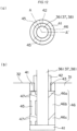
- FIG. 9 is a diagram illustrating constraint conditions in a three-dimensional space at the time of fixing the cylindrical support rod 36 to the base 31.
- Fig. 10 is a diagram illustrating force transmission by wedge-shaped blocks.
- the load transmitting block 46 When the loading bolt 42 is fastened to the cylindrical member 41, the load transmitting block 46 is applied with force along the long axis direction of the block.
- the length of the load transmitting block 46 in the long axis direction, in which the three wedge-shaped members 46a, 46b, 46c are combined, is made sufficiently larger than the length of the fixing blocks 45 in the long axis direction. In doing so, when the loading bolt 42 is fastened, the loading bolt 42 does not abut on the upper end parts of the fixing blocks 45, and a load at the time is transmitted only to the load transmitting block 46.
- the wedge-shaped member 46a in direct contact with the loading bolt 42 slides and slightly moves to the support rod 36 side because of the tilts of the tilt surfaces with which the wedge-shaped member 46a and the wedge-shaped member 46b are in contact, and is thereby pressed against the outer circumferential surface of the support rod 36.
- the motion of the support rod 36 in the rotational direction is constrained by the frictional force between the outer circumferential surface of the support rod 36 and the surface of the wedge-shaped member 46a.
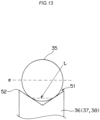
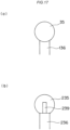
- a conical concave part 51 for placing the sphere 35 is formed as in the structure illustrated in Fig. 13 .
- the tip of the support rod 36 illustrated in Fig. 14 is provided with a through-hole 54 passing from the bottom of the conical concave part 51 to the outer surface of the support rod 36.
- the through-hole 54 is one for allowing bond at the time of fixing the sphere 35 to escape to the outside of the conical concave part 51.
- an embodiment illustrated in Fig. 14 is adapted to allow the bond to more easily escape in such a manner that the through-hole 54 communicates to the outer surface of the support rod 36; however, the through-hole 54 is not necessarily required to be made penetrate to the outer surface of the support rod 36. Only by providing the bottom of the conical concave part 51 with a thin columnar concave part, the same degree of effect can be obtained.
- the XYZ space in which the respective spheres 35 are arranged is covered with the cover 33.
- the number of spheres 35 is suppressed to 15, and therefore the coordinate measurement by the CMM can be quickly performed. Further, the number of parts can be reduced than before, and therefore the fabrication cost of the utensil 30 can also be suppressed.
- the utensil 30 When performing the X-ray CT imaging on the utensil 30, the utensil 30 is positioned with the cover 33 attached on the rotation stage 13, and the X-ray CT imaging is performed.
- the projection coordinates (Xi, Yi) of the respective spheres 35 are almost uniform, and the positions of the three X-Y planes having different Z positions are also almost uniform in the Z direction, so that the 15 spheres 35 arranged in the XYZ space are not structured such that they are arranged on conical surfaces as conventional, and respectively have appropriate distance intervals.
- Such sphere arrangement enables spatial distortion specific to an X-ray CT device to be sufficiently captured.
- an evaluation range in the Z axis direction in an imaging visual space by one time of X-ray CT imaging can be more widened than in a conventional utensil having a step-wise base.
- the difference in length (e.g., 60 mm) between the support rod 36 having the shortest length and the support rod 38 having the longest length is made longer than the radius (50 mm) of the circle around the origin (0, 0) of the projection coordinates illustrated in Fig. 4 .
- the arrangement range of the multiple spheres is such that among the multiple X-Y planes, the distance in the Z direction between the X-Y plane having the lowest Z position and the X-Y plane having the highest Z position is larger than the distance from the Z axis in the XY directions.
- the number of times of performing repeated measurement with a Z axis position changed can be reduced than before, and therefore imaging time for evaluating the measurement accuracy of an X-ray CT device can be reduced.
- the ratio between the vertical and horizontal sizes of the X-ray detector 12 is one, among the multiple X-Y planes, the distance in the Z direction between the X-Y plane having the lowest Z position and the X-Y plane having the highest Z position, and a distance twice as long as the distance from the Z axis in the XY directions are preferably almost the same.
- the arrangement range of the spheres 35 is only required to be changed depending on the size of the X-ray detector 12, the bending length of the material of the support rods 36, 37, 38, and the like in a range where among the multiple X-Y planes, the distance in the Z direction between the X-Y plane having the lowest Z position and the X-Y plane having the highest Z position is larger than the distance from the Z axis in the XY directions (the radius of the circle around the origin (0, 0) of the projection coordinates illustrated in Fig. 4 ) and smaller than or almost equal to twice as long as the distance from the Z axis in the XY directions (the diameter of the circle around the origin (0, 0) of the projection coordinates illustrated in Fig. 4 ).
Landscapes
- Health & Medical Sciences (AREA)
- Life Sciences & Earth Sciences (AREA)
- Physics & Mathematics (AREA)
- Engineering & Computer Science (AREA)
- Medical Informatics (AREA)
- Pathology (AREA)
- General Health & Medical Sciences (AREA)
- Nuclear Medicine, Radiotherapy & Molecular Imaging (AREA)
- General Physics & Mathematics (AREA)
- Surgery (AREA)
- Radiology & Medical Imaging (AREA)
- Veterinary Medicine (AREA)
- Public Health (AREA)
- Animal Behavior & Ethology (AREA)
- Molecular Biology (AREA)
- Biomedical Technology (AREA)
- Heart & Thoracic Surgery (AREA)
- Biophysics (AREA)
- Optics & Photonics (AREA)
- High Energy & Nuclear Physics (AREA)
- Theoretical Computer Science (AREA)
- Pulmonology (AREA)
- Electromagnetism (AREA)
- Immunology (AREA)
- Analytical Chemistry (AREA)
- Chemical & Material Sciences (AREA)
- Biochemistry (AREA)
- Oral & Maxillofacial Surgery (AREA)
- Apparatus For Radiation Diagnosis (AREA)
- Analysing Materials By The Use Of Radiation (AREA)
- Length-Measuring Devices Using Wave Or Particle Radiation (AREA)
Claims (2)
- Utensil (30) zum Auswerten eines Längenmessfehlers in einer Röntgen-CT-Vorrichtung zur dreidimensionalen Formmessung, wobei das Utensil (30) zur Verwendung an einem Drehgestell der Röntgen-CT-Vorrichtung zur dreidimensionalen Formmessung derart konfiguriert ist, dass eine Z-Achse als eine Drehachse des Drehgestells mit einem Mittelpunkt eines zylindrischen Abbildungsraums zusammenfällt, wobei das Utensil (30) aufweist:eine Basis (31);mehrere Kugeln (35), die in einem XYZ-Raum an der Basis (31) angeordnet sind, der dem Abbildungsraum entspricht; undmehrere Stützstangen (36, 37, 38), die jede der mehreren Kugeln (35) stützen und aufrecht an der Basis (31) installiert sind, wobei:
die mehreren Kugeln (35) mehrere außenumfangsseitige Kugeln (35) aufweisen, die auf einem äußeren Umfangskreis um die Z-Achse in jeder der mehreren X-Y-Ebenen mit unterschiedlichen Z-Positionen angeordnet sind, wobei:eine oder mehrere Kugeln in der Nähe der Z-Achse angeordnet sind,ein Radius eines äußeren Umfangskreises, auf dem die mehreren außenumfangsseitigen Kugeln (35) in jeder der mehreren X-Y-Ebenen angeordnet sind, gleich ist und die Koordinaten (X, Y) der mehreren außenumfangsseitigen Kugeln, die in allen der mehreren X-Y-Ebenen angeordnet sind, unterschiedlich sind; unddie mehreren außenumfangsseitigen Kugeln (35) zwei Sätze aus zwei Kugeln (35) aufweisen, die in Bezug auf die Z-Achse symmetrisch angeordnet sind. - Utensil (30) zum Auswerten eines Längenmessfehlers in einer Röntgen-CT-Vorrichtung zur dreidimensionalen Formmessung, wobei das Utensil (30) zur Verwendung an einem Drehgestell der Röntgen-CT-Vorrichtung zur dreidimensionalen Formmessung derart konfiguriert ist, dass eine Z-Achse als eine Drehachse des Drehgestells mit einem Mittelpunkt eines zylindrischen Abbildungsraums zusammenfällt, wobei das Utensil (30) aufweist:eine Basis (31); undmehrere Kugeln (35), die in einem XYZ-Raum an der Basis (31) angeordnet sind, der dem Abbildungsraum entspricht; undmehrere Stützstangen (36, 37, 38), die jede der mehreren Kugeln (35) stützen und aufrecht an der Basis (31) installiert sind, wobei:
die mehreren Kugeln (35) mehrere außenumfangsseitige Kugeln (35) beinhalten, die auf einem äußeren Umfangskreis um die Z-Achse in jeder der mehreren X-Y-Ebenen mit unterschiedlichen Z-Positionen angeordnet sind, und wobei:eine oder mehrere Kugeln in der Nähe der Z-Achse angeordnet sind,ein Radius eines äußeren Umfangskreises, auf dem die mehreren außenumfangsseitigen Kugeln (35) in jeder der mehreren X-Y-Ebenen angeordnet sind, gleich ist und die Koordinaten (X, Y) der mehreren außenumfangsseitigen Kugeln (35), die in allen der mehreren X-Y-Ebenen angeordnet sind, unterschiedlich sind; unddie mehreren außenumfangsseitigen Kugeln (35) in jeder X-Y-Ebene so angeordnet sind, dass eine Projektionsposition auf einer X-Y-Referenzebene, deren Z-Koordinate Null ist, in regelmäßigen Abständen entlang eines Kreises um die Z-Achse platziert ist.
Applications Claiming Priority (3)
| Application Number | Priority Date | Filing Date | Title |
|---|---|---|---|
| JP2017084774 | 2017-04-21 | ||
| PCT/JP2018/012546 WO2018193800A1 (ja) | 2017-04-21 | 2018-03-27 | 三次元形状測定用x線ct装置の長さ測定誤差評価用器物 |
| EP18787433.4A EP3614099B1 (de) | 2017-04-21 | 2018-03-27 | Utensil zur auswertung von längenmessfehlern in einer röntgen-ct-vorrichtung zur dreidimensionalen formmessung |
Related Parent Applications (1)
| Application Number | Title | Priority Date | Filing Date |
|---|---|---|---|
| EP18787433.4A Division EP3614099B1 (de) | 2017-04-21 | 2018-03-27 | Utensil zur auswertung von längenmessfehlern in einer röntgen-ct-vorrichtung zur dreidimensionalen formmessung |
Publications (2)
| Publication Number | Publication Date |
|---|---|
| EP4019893A1 EP4019893A1 (de) | 2022-06-29 |
| EP4019893B1 true EP4019893B1 (de) | 2025-07-02 |
Family
ID=63855883
Family Applications (2)
| Application Number | Title | Priority Date | Filing Date |
|---|---|---|---|
| EP22156521.1A Active EP4019893B1 (de) | 2017-04-21 | 2018-03-27 | Utensil zur auswertung von längenmessfehlern in einer röntgen-ct-vorrichtung zur dreidimensionalen formmessung |
| EP18787433.4A Active EP3614099B1 (de) | 2017-04-21 | 2018-03-27 | Utensil zur auswertung von längenmessfehlern in einer röntgen-ct-vorrichtung zur dreidimensionalen formmessung |
Family Applications After (1)
| Application Number | Title | Priority Date | Filing Date |
|---|---|---|---|
| EP18787433.4A Active EP3614099B1 (de) | 2017-04-21 | 2018-03-27 | Utensil zur auswertung von längenmessfehlern in einer röntgen-ct-vorrichtung zur dreidimensionalen formmessung |
Country Status (5)
| Country | Link |
|---|---|
| US (2) | US11291425B2 (de) |
| EP (2) | EP4019893B1 (de) |
| JP (3) | JP6901733B2 (de) |
| CN (2) | CN113624169B (de) |
| WO (1) | WO2018193800A1 (de) |
Families Citing this family (10)
| Publication number | Priority date | Publication date | Assignee | Title |
|---|---|---|---|---|
| EP4019893B1 (de) * | 2017-04-21 | 2025-07-02 | Shimadzu Corporation | Utensil zur auswertung von längenmessfehlern in einer röntgen-ct-vorrichtung zur dreidimensionalen formmessung |
| JP2019158541A (ja) * | 2018-03-12 | 2019-09-19 | 株式会社ミツトヨ | 計測用x線ct装置、及び、その量産ワーク測定方法 |
| CN111060042A (zh) * | 2019-12-30 | 2020-04-24 | 中国工程物理研究院应用电子学研究所 | 一种基于球模体进行工业ct几何尺寸测量不确定度的方法 |
| JP7366467B2 (ja) * | 2020-07-17 | 2023-10-23 | 国立研究開発法人産業技術総合研究所 | X線ct装置の評価用器具 |
| CN113048865B (zh) * | 2021-03-15 | 2024-03-05 | 西北工业大学 | 层析测量角度校准块 |
| JP7563282B2 (ja) | 2021-04-16 | 2024-10-08 | 株式会社島津製作所 | Ct装置評価用ファントム |
| JP7665463B2 (ja) * | 2021-07-26 | 2025-04-21 | 株式会社ミツトヨ | 座標測定装置用点検ゲージ及び異常判定方法 |
| PL243321B1 (pl) * | 2021-09-28 | 2023-08-07 | Politechnika Slaska Im Wincent | Układ do wyznaczania korekty na samopochłanianie w spektrometrii promieniowania γ i X |
| CN116448792A (zh) * | 2023-03-16 | 2023-07-18 | 北京航天计量测试技术研究所 | 一种可溯源的工业ct森林球校准器装置 |
| CN119618116A (zh) * | 2023-09-12 | 2025-03-14 | 中国航发商用航空发动机有限责任公司 | 尺寸测量综合参数校准球组靶的校准方法 |
Family Cites Families (34)
| Publication number | Priority date | Publication date | Assignee | Title |
|---|---|---|---|---|
| DE19856537A1 (de) * | 1998-12-08 | 2000-06-15 | Philips Corp Intellectual Pty | Verfahren zur intraoperativen Kalibration von C-Bogen Röntgenanordnungen |
| JP2003061944A (ja) * | 2001-08-29 | 2003-03-04 | Shimadzu Corp | 断層撮影装置の校正方法 |
| EP1346687B1 (de) * | 2002-02-22 | 2007-03-21 | BrainLAB AG | Verfahren zur Navigations-Kalibrierung von Röntgenbilddaten und höhenreduziertes Kalibrierungsinstrument |
| JP2004229854A (ja) * | 2003-01-30 | 2004-08-19 | Shimadzu Corp | コーンビームct装置により撮像したct画像の歪み修正方法 |
| US7186023B2 (en) * | 2003-06-10 | 2007-03-06 | Shimadzu Corporation | Slice image and/or dimensional image creating method |
| JP4415762B2 (ja) * | 2003-06-10 | 2010-02-17 | 株式会社島津製作所 | 断層撮影装置 |
| EP2192380A3 (de) * | 2004-05-26 | 2010-06-23 | Werth Messtechnik GmbH | Verfahren zum Messen eines Objektes mit einem Koordinatenmessgerät sowie Koordinatenmessgerät |
| DE202006019649U1 (de) * | 2006-12-22 | 2007-08-16 | Brainlab Ag | Navigierte Applikationsführung für gezielte Spinalarzneimittelzufuhr |
| JP2008180557A (ja) | 2007-01-23 | 2008-08-07 | Tohoku Univ | 接触式変位センサのスタイラス及びその製造装置並びに接触式変位センサ |
| CN101615293B (zh) * | 2009-08-12 | 2011-11-09 | 中国人民解放军信息工程大学 | Vct系统参数标定装置及方法 |
| CN201765199U (zh) * | 2010-03-15 | 2011-03-16 | 中国工程物理研究院应用电子学研究所 | 一种适用于锥束xct系统中的二自由度转台 |
| US20130195255A1 (en) * | 2010-05-12 | 2013-08-01 | Ricardo Avila | Calibration Phantom Device and Analysis Methods |
| US8777485B2 (en) * | 2010-09-24 | 2014-07-15 | Varian Medical Systems, Inc. | Method and apparatus pertaining to computed tomography scanning using a calibration phantom |
| JP5126331B2 (ja) * | 2010-09-30 | 2013-01-23 | ブラザー工業株式会社 | 液体吐出装置、制御装置、及びプログラム |
| US8947356B2 (en) * | 2011-03-31 | 2015-02-03 | Empire Technology Development Llc | Suspended input system |
| CN102727232B (zh) * | 2011-04-08 | 2014-02-19 | 上海优益基医疗器械有限公司 | 外科手术导航系统定位精度检测装置及方法 |
| CN103517736B (zh) * | 2011-04-29 | 2016-06-29 | 医科达公司 | 标定和质量保证的方法 |
| CN202104929U (zh) * | 2011-05-11 | 2012-01-11 | 上海生物医学工程研究中心 | 一种用于体ct几何校正的装置 |
| CN202355419U (zh) * | 2011-08-19 | 2012-08-01 | 深圳市贝斯达医疗器械有限公司 | 一种x射线ct装置 |
| EP2809234B1 (de) * | 2012-01-30 | 2018-04-25 | Hexagon Metrology, Inc | Vorrichtung zur kalibrierung und prüfung einer röntgencomputertomographievorrichtung |
| US9907494B2 (en) * | 2012-04-18 | 2018-03-06 | Hutchinson Technology Incorporated | NIRS device with optical wavelength and path length correction |
| EP2737852B1 (de) * | 2012-11-30 | 2015-08-19 | GE Sensing & Inspection Technologies GmbH | Verfahren zum Erfassen geometrischer Abbildungseigenschaften eines Flachbilddetektors, entsprechend eingerichtete Röntgenprüfanlage und Kalibrierkörper |
| EP2954286B1 (de) * | 2013-02-11 | 2018-04-11 | Nikon Metrology NV | Kalibrierungsartefakt für röntgen-computertomographiesystem |
| JP6205569B2 (ja) * | 2013-03-28 | 2017-10-04 | 群馬県 | X線ct装置の校正器 |
| DE102014113977A1 (de) * | 2013-10-22 | 2015-04-23 | Werth Messtechnik Gmbh | Verfahren zur Bestimmung zumindest eines Parameters bei der dimensionellen Messung mit einer Computertomografiesensorik |
| GB2520711B (en) * | 2013-11-28 | 2018-06-20 | Nikon Metrology Nv | Calibration apparatus and method for computed tomography |
| US9750479B2 (en) * | 2014-06-27 | 2017-09-05 | Hexagon Metrology, Inc. | Three-dimensional x-ray CT calibration and verification apparatus and method |
| US10034651B2 (en) * | 2014-07-18 | 2018-07-31 | Gammex, Inc. | Brain tissue equivalent material and phantom device comprising the same |
| CN104490413A (zh) * | 2014-12-05 | 2015-04-08 | 杭州市肿瘤医院 | 一种体外定位标以及应用该定位标的定位配准方法 |
| US10222492B2 (en) * | 2015-10-23 | 2019-03-05 | Hexagon Metrology, Inc. | Three-dimensional computed tomography gauge |
| JP3206123U (ja) | 2016-06-20 | 2016-09-01 | 株式会社柳田エンジニアリング | 穴位置測定用治具 |
| CN106419837A (zh) * | 2016-08-26 | 2017-02-22 | 西北大学 | 基于螺旋式激发的荧光分子断层成像系统 |
| JP7038399B2 (ja) * | 2016-10-13 | 2022-03-18 | 地方独立行政法人東京都立産業技術研究センター | Ct装置用校正器 |
| EP4019893B1 (de) * | 2017-04-21 | 2025-07-02 | Shimadzu Corporation | Utensil zur auswertung von längenmessfehlern in einer röntgen-ct-vorrichtung zur dreidimensionalen formmessung |
-
2018
- 2018-03-27 EP EP22156521.1A patent/EP4019893B1/de active Active
- 2018-03-27 WO PCT/JP2018/012546 patent/WO2018193800A1/ja not_active Ceased
- 2018-03-27 CN CN202110902766.9A patent/CN113624169B/zh active Active
- 2018-03-27 JP JP2019513529A patent/JP6901733B2/ja active Active
- 2018-03-27 CN CN201880025507.9A patent/CN110520689B/zh active Active
- 2018-03-27 US US16/485,639 patent/US11291425B2/en active Active
- 2018-03-27 EP EP18787433.4A patent/EP3614099B1/de active Active
-
2019
- 2019-08-28 JP JP2019155611A patent/JP6883810B2/ja not_active Expired - Fee Related
-
2021
- 2021-03-04 JP JP2021034316A patent/JP7164130B2/ja active Active
-
2022
- 2022-02-23 US US17/678,726 patent/US11998382B2/en active Active
Also Published As
| Publication number | Publication date |
|---|---|
| JP2021099363A (ja) | 2021-07-01 |
| WO2018193800A1 (ja) | 2018-10-25 |
| JP2020020799A (ja) | 2020-02-06 |
| US20220175337A1 (en) | 2022-06-09 |
| EP4019893A1 (de) | 2022-06-29 |
| CN113624169B (zh) | 2024-07-23 |
| JP7164130B2 (ja) | 2022-11-01 |
| US11291425B2 (en) | 2022-04-05 |
| CN110520689B (zh) | 2021-09-07 |
| US11998382B2 (en) | 2024-06-04 |
| EP3614099B1 (de) | 2022-02-16 |
| US20210282734A1 (en) | 2021-09-16 |
| EP3614099A4 (de) | 2020-12-30 |
| CN110520689A (zh) | 2019-11-29 |
| CN113624169A (zh) | 2021-11-09 |
| JP6901733B2 (ja) | 2021-07-14 |
| EP3614099A1 (de) | 2020-02-26 |
| JP6883810B2 (ja) | 2021-06-09 |
| JPWO2018193800A1 (ja) | 2020-02-06 |
Similar Documents
| Publication | Publication Date | Title |
|---|---|---|
| US11998382B2 (en) | Utensil for evaluating length measurement error in X-ray CT device for three-dimensional shape measurement | |
| CN108007400B (zh) | 用于坐标测量装置和测量x射线ct设备的坐标对准工具 | |
| CN201199234Y (zh) | 分层摄影检测系统 | |
| JP7273185B2 (ja) | ロボット用の座標系アライメント方法及びアライメントシステム並びにアライメント装置 | |
| CN109549667A (zh) | 超声换能器扫描系统、方法及超声成像设备 | |
| JP6711410B2 (ja) | 放射線断層撮影装置の撮像倍率校正方法 | |
| JP2004257927A (ja) | 3次元形状測定システムおよび3次元形状測定方法 | |
| Butzhammer et al. | Complex 3D scan trajectories for industrial cone-beam computed tomography using a hexapod | |
| CN108426901A (zh) | 一种x射线分层扫描成像系统 | |
| JP7038399B2 (ja) | Ct装置用校正器 | |
| EP3195802A1 (de) | Geometrische kalibrierung eines röntgen-ct-scanners | |
| CN203776924U (zh) | 一种锥束ct系统几何位置的校正装置 | |
| Landstorfer et al. | Investigation of positioning accuracy of industrial robots for robotic-based X-ray computed tomography | |
| JP6661391B2 (ja) | 放射線画像撮影装置 | |
| JP2020186913A (ja) | X線ct装置、及びct画像再構成方法 | |
| CN207114458U (zh) | 一种ct层析系统探测器位姿调整装置 | |
| JP2019158541A (ja) | 計測用x線ct装置、及び、その量産ワーク測定方法 | |
| CN104374786B (zh) | 一种同步辐射x射线ct校轴系统及方法 | |
| JP7213108B2 (ja) | 締結システム及び締結方法 | |
| JP2017203717A (ja) | 接着剤塗布装置、及び接着剤塗布形状の測定方法 | |
| CN115707958A (zh) | 三维形状的对位方法以及三维形状数据处理装置 | |
| JP2011185853A (ja) | 曲率中心検出装置及びこれを使用した孔位置検出方法 | |
| CN107462590A (zh) | 一种ct层析系统探测器位姿调整装置 | |
| JP2023097826A (ja) | 検査装置、及び検査装置の調整方法 | |
| Frank | 2D or 3D? benefits of combining both in a single X-ray system |
Legal Events
| Date | Code | Title | Description |
|---|---|---|---|
| PUAI | Public reference made under article 153(3) epc to a published international application that has entered the european phase |
Free format text: ORIGINAL CODE: 0009012 |
|
| STAA | Information on the status of an ep patent application or granted ep patent |
Free format text: STATUS: REQUEST FOR EXAMINATION WAS MADE |
|
| 17P | Request for examination filed |
Effective date: 20220217 |
|
| AC | Divisional application: reference to earlier application |
Ref document number: 3614099 Country of ref document: EP Kind code of ref document: P |
|
| AK | Designated contracting states |
Kind code of ref document: A1 Designated state(s): AL AT BE BG CH CY CZ DE DK EE ES FI FR GB GR HR HU IE IS IT LI LT LU LV MC MK MT NL NO PL PT RO RS SE SI SK SM TR |
|
| RBV | Designated contracting states (corrected) |
Designated state(s): AL AT BE BG CH CY CZ DE DK EE ES FI FR GB GR HR HU IE IS IT LI LT LU LV MC MK MT NL NO PL PT RO RS SE SI SK SM TR |
|
| STAA | Information on the status of an ep patent application or granted ep patent |
Free format text: STATUS: EXAMINATION IS IN PROGRESS |
|
| 17Q | First examination report despatched |
Effective date: 20240117 |
|
| GRAP | Despatch of communication of intention to grant a patent |
Free format text: ORIGINAL CODE: EPIDOSNIGR1 |
|
| STAA | Information on the status of an ep patent application or granted ep patent |
Free format text: STATUS: GRANT OF PATENT IS INTENDED |
|
| RIC1 | Information provided on ipc code assigned before grant |
Ipc: A61B 6/03 20060101ALN20250207BHEP Ipc: G01N 23/046 20180101ALI20250207BHEP Ipc: A61B 6/58 20240101ALI20250207BHEP Ipc: G01B 21/04 20060101ALI20250207BHEP Ipc: G01B 15/04 20060101AFI20250207BHEP |
|
| RIC1 | Information provided on ipc code assigned before grant |
Ipc: A61B 6/03 20060101ALN20250226BHEP Ipc: G01N 23/046 20180101ALI20250226BHEP Ipc: A61B 6/58 20240101ALI20250226BHEP Ipc: G01B 21/04 20060101ALI20250226BHEP Ipc: G01B 15/04 20060101AFI20250226BHEP |
|
| RIC1 | Information provided on ipc code assigned before grant |
Ipc: A61B 6/03 20060101ALN20250305BHEP Ipc: G01N 23/046 20180101ALI20250305BHEP Ipc: A61B 6/58 20240101ALI20250305BHEP Ipc: G01B 21/04 20060101ALI20250305BHEP Ipc: G01B 15/04 20060101AFI20250305BHEP |
|
| INTG | Intention to grant announced |
Effective date: 20250319 |
|
| GRAS | Grant fee paid |
Free format text: ORIGINAL CODE: EPIDOSNIGR3 |
|
| GRAA | (expected) grant |
Free format text: ORIGINAL CODE: 0009210 |
|
| STAA | Information on the status of an ep patent application or granted ep patent |
Free format text: STATUS: THE PATENT HAS BEEN GRANTED |
|
| AC | Divisional application: reference to earlier application |
Ref document number: 3614099 Country of ref document: EP Kind code of ref document: P |
|
| AK | Designated contracting states |
Kind code of ref document: B1 Designated state(s): AL AT BE BG CH CY CZ DE DK EE ES FI FR GB GR HR HU IE IS IT LI LT LU LV MC MK MT NL NO PL PT RO RS SE SI SK SM TR |
|
| REG | Reference to a national code |
Ref country code: GB Ref legal event code: FG4D |
|
| REG | Reference to a national code |
Ref country code: CH Ref legal event code: EP |
|
| REG | Reference to a national code |
Ref country code: DE Ref legal event code: R096 Ref document number: 602018083340 Country of ref document: DE |
|
| REG | Reference to a national code |
Ref country code: IE Ref legal event code: FG4D |
|
| REG | Reference to a national code |
Ref country code: NL Ref legal event code: MP Effective date: 20250702 |
|
| PG25 | Lapsed in a contracting state [announced via postgrant information from national office to epo] |
Ref country code: PT Free format text: LAPSE BECAUSE OF FAILURE TO SUBMIT A TRANSLATION OF THE DESCRIPTION OR TO PAY THE FEE WITHIN THE PRESCRIBED TIME-LIMIT Effective date: 20251103 |
|
| PG25 | Lapsed in a contracting state [announced via postgrant information from national office to epo] |
Ref country code: NL Free format text: LAPSE BECAUSE OF FAILURE TO SUBMIT A TRANSLATION OF THE DESCRIPTION OR TO PAY THE FEE WITHIN THE PRESCRIBED TIME-LIMIT Effective date: 20250702 |
|
| REG | Reference to a national code |
Ref country code: AT Ref legal event code: MK05 Ref document number: 1809660 Country of ref document: AT Kind code of ref document: T Effective date: 20250702 |
|
| PG25 | Lapsed in a contracting state [announced via postgrant information from national office to epo] |
Ref country code: IS Free format text: LAPSE BECAUSE OF FAILURE TO SUBMIT A TRANSLATION OF THE DESCRIPTION OR TO PAY THE FEE WITHIN THE PRESCRIBED TIME-LIMIT Effective date: 20251102 |
|
| PG25 | Lapsed in a contracting state [announced via postgrant information from national office to epo] |
Ref country code: NO Free format text: LAPSE BECAUSE OF FAILURE TO SUBMIT A TRANSLATION OF THE DESCRIPTION OR TO PAY THE FEE WITHIN THE PRESCRIBED TIME-LIMIT Effective date: 20251002 |
|
| REG | Reference to a national code |
Ref country code: LT Ref legal event code: MG9D |
|
| PG25 | Lapsed in a contracting state [announced via postgrant information from national office to epo] |
Ref country code: AT Free format text: LAPSE BECAUSE OF FAILURE TO SUBMIT A TRANSLATION OF THE DESCRIPTION OR TO PAY THE FEE WITHIN THE PRESCRIBED TIME-LIMIT Effective date: 20250702 |
|
| PG25 | Lapsed in a contracting state [announced via postgrant information from national office to epo] |
Ref country code: FI Free format text: LAPSE BECAUSE OF FAILURE TO SUBMIT A TRANSLATION OF THE DESCRIPTION OR TO PAY THE FEE WITHIN THE PRESCRIBED TIME-LIMIT Effective date: 20250702 |
|
| PG25 | Lapsed in a contracting state [announced via postgrant information from national office to epo] |
Ref country code: HR Free format text: LAPSE BECAUSE OF FAILURE TO SUBMIT A TRANSLATION OF THE DESCRIPTION OR TO PAY THE FEE WITHIN THE PRESCRIBED TIME-LIMIT Effective date: 20250702 |
|
| PG25 | Lapsed in a contracting state [announced via postgrant information from national office to epo] |
Ref country code: GR Free format text: LAPSE BECAUSE OF FAILURE TO SUBMIT A TRANSLATION OF THE DESCRIPTION OR TO PAY THE FEE WITHIN THE PRESCRIBED TIME-LIMIT Effective date: 20251003 |
|
| PG25 | Lapsed in a contracting state [announced via postgrant information from national office to epo] |
Ref country code: CZ Free format text: LAPSE BECAUSE OF FAILURE TO SUBMIT A TRANSLATION OF THE DESCRIPTION OR TO PAY THE FEE WITHIN THE PRESCRIBED TIME-LIMIT Effective date: 20250702 Ref country code: SE Free format text: LAPSE BECAUSE OF FAILURE TO SUBMIT A TRANSLATION OF THE DESCRIPTION OR TO PAY THE FEE WITHIN THE PRESCRIBED TIME-LIMIT Effective date: 20250702 |
|
| PG25 | Lapsed in a contracting state [announced via postgrant information from national office to epo] |
Ref country code: LV Free format text: LAPSE BECAUSE OF FAILURE TO SUBMIT A TRANSLATION OF THE DESCRIPTION OR TO PAY THE FEE WITHIN THE PRESCRIBED TIME-LIMIT Effective date: 20250702 |
|
| PG25 | Lapsed in a contracting state [announced via postgrant information from national office to epo] |
Ref country code: PL Free format text: LAPSE BECAUSE OF FAILURE TO SUBMIT A TRANSLATION OF THE DESCRIPTION OR TO PAY THE FEE WITHIN THE PRESCRIBED TIME-LIMIT Effective date: 20250702 Ref country code: BG Free format text: LAPSE BECAUSE OF FAILURE TO SUBMIT A TRANSLATION OF THE DESCRIPTION OR TO PAY THE FEE WITHIN THE PRESCRIBED TIME-LIMIT Effective date: 20250702 |
|
| PG25 | Lapsed in a contracting state [announced via postgrant information from national office to epo] |
Ref country code: RS Free format text: LAPSE BECAUSE OF FAILURE TO SUBMIT A TRANSLATION OF THE DESCRIPTION OR TO PAY THE FEE WITHIN THE PRESCRIBED TIME-LIMIT Effective date: 20251002 |
|
| PG25 | Lapsed in a contracting state [announced via postgrant information from national office to epo] |
Ref country code: ES Free format text: LAPSE BECAUSE OF FAILURE TO SUBMIT A TRANSLATION OF THE DESCRIPTION OR TO PAY THE FEE WITHIN THE PRESCRIBED TIME-LIMIT Effective date: 20250702 |
|
| PG25 | Lapsed in a contracting state [announced via postgrant information from national office to epo] |
Ref country code: SM Free format text: LAPSE BECAUSE OF FAILURE TO SUBMIT A TRANSLATION OF THE DESCRIPTION OR TO PAY THE FEE WITHIN THE PRESCRIBED TIME-LIMIT Effective date: 20250702 |
|
| PGFP | Annual fee paid to national office [announced via postgrant information from national office to epo] |
Ref country code: GB Payment date: 20260209 Year of fee payment: 9 |
|
| PG25 | Lapsed in a contracting state [announced via postgrant information from national office to epo] |
Ref country code: DK Free format text: LAPSE BECAUSE OF FAILURE TO SUBMIT A TRANSLATION OF THE DESCRIPTION OR TO PAY THE FEE WITHIN THE PRESCRIBED TIME-LIMIT Effective date: 20250702 |
|
| PGFP | Annual fee paid to national office [announced via postgrant information from national office to epo] |
Ref country code: DE Payment date: 20260128 Year of fee payment: 9 |
|
| PG25 | Lapsed in a contracting state [announced via postgrant information from national office to epo] |
Ref country code: IT Free format text: LAPSE BECAUSE OF FAILURE TO SUBMIT A TRANSLATION OF THE DESCRIPTION OR TO PAY THE FEE WITHIN THE PRESCRIBED TIME-LIMIT Effective date: 20250702 |
|
| PGFP | Annual fee paid to national office [announced via postgrant information from national office to epo] |
Ref country code: FR Payment date: 20260209 Year of fee payment: 9 |