EP4019822B1 - Verbindungsgelenk zur verbindung von komponenten eines laborautomatisierungssystems - Google Patents
Verbindungsgelenk zur verbindung von komponenten eines laborautomatisierungssystems Download PDFInfo
- Publication number
- EP4019822B1 EP4019822B1 EP20216535.3A EP20216535A EP4019822B1 EP 4019822 B1 EP4019822 B1 EP 4019822B1 EP 20216535 A EP20216535 A EP 20216535A EP 4019822 B1 EP4019822 B1 EP 4019822B1
- Authority
- EP
- European Patent Office
- Prior art keywords
- laboratory
- bearing unit
- automation system
- slider bar
- connecting joint
- Prior art date
- Legal status (The legal status is an assumption and is not a legal conclusion. Google has not performed a legal analysis and makes no representation as to the accuracy of the status listed.)
- Active
Links
Images

Classifications
-
- F—MECHANICAL ENGINEERING; LIGHTING; HEATING; WEAPONS; BLASTING
- F16—ENGINEERING ELEMENTS AND UNITS; GENERAL MEASURES FOR PRODUCING AND MAINTAINING EFFECTIVE FUNCTIONING OF MACHINES OR INSTALLATIONS; THERMAL INSULATION IN GENERAL
- F16B—DEVICES FOR FASTENING OR SECURING CONSTRUCTIONAL ELEMENTS OR MACHINE PARTS TOGETHER, e.g. NAILS, BOLTS, CIRCLIPS, CLAMPS, CLIPS OR WEDGES; JOINTS OR JOINTING
- F16B1/00—Devices for securing together, or preventing relative movement between, constructional elements or machine parts
- F16B1/02—Means for securing elements of mechanisms after operation
-
- F—MECHANICAL ENGINEERING; LIGHTING; HEATING; WEAPONS; BLASTING
- F16—ENGINEERING ELEMENTS AND UNITS; GENERAL MEASURES FOR PRODUCING AND MAINTAINING EFFECTIVE FUNCTIONING OF MACHINES OR INSTALLATIONS; THERMAL INSULATION IN GENERAL
- F16B—DEVICES FOR FASTENING OR SECURING CONSTRUCTIONAL ELEMENTS OR MACHINE PARTS TOGETHER, e.g. NAILS, BOLTS, CIRCLIPS, CLAMPS, CLIPS OR WEDGES; JOINTS OR JOINTING
- F16B7/00—Connections of rods or tubes, e.g. of non-circular section, mutually, including resilient connections
- F16B7/18—Connections of rods or tubes, e.g. of non-circular section, mutually, including resilient connections using screw-thread elements
- F16B7/187—Connections of rods or tubes, e.g. of non-circular section, mutually, including resilient connections using screw-thread elements with sliding nuts or other additional connecting members for joining profiles provided with grooves or channels
-
- F—MECHANICAL ENGINEERING; LIGHTING; HEATING; WEAPONS; BLASTING
- F16—ENGINEERING ELEMENTS AND UNITS; GENERAL MEASURES FOR PRODUCING AND MAINTAINING EFFECTIVE FUNCTIONING OF MACHINES OR INSTALLATIONS; THERMAL INSULATION IN GENERAL
- F16C—SHAFTS; FLEXIBLE SHAFTS; ELEMENTS OR CRANKSHAFT MECHANISMS; ROTARY BODIES OTHER THAN GEARING ELEMENTS; BEARINGS
- F16C11/00—Pivots; Pivotal connections
- F16C11/04—Pivotal connections
-
- F—MECHANICAL ENGINEERING; LIGHTING; HEATING; WEAPONS; BLASTING
- F16—ENGINEERING ELEMENTS AND UNITS; GENERAL MEASURES FOR PRODUCING AND MAINTAINING EFFECTIVE FUNCTIONING OF MACHINES OR INSTALLATIONS; THERMAL INSULATION IN GENERAL
- F16M—FRAMES, CASINGS OR BEDS OF ENGINES, MACHINES OR APPARATUS, NOT SPECIFIC TO ENGINES, MACHINES OR APPARATUS PROVIDED FOR ELSEWHERE; STANDS; SUPPORTS
- F16M11/00—Stands or trestles as supports for apparatus or articles placed thereon ; Stands for scientific apparatus such as gravitational force meters
- F16M11/02—Heads
- F16M11/04—Means for attachment of apparatus; Means allowing adjustment of the apparatus relatively to the stand
- F16M11/043—Allowing translations
- F16M11/045—Allowing translations adapted to left-right translation movement
-
- F—MECHANICAL ENGINEERING; LIGHTING; HEATING; WEAPONS; BLASTING
- F16—ENGINEERING ELEMENTS AND UNITS; GENERAL MEASURES FOR PRODUCING AND MAINTAINING EFFECTIVE FUNCTIONING OF MACHINES OR INSTALLATIONS; THERMAL INSULATION IN GENERAL
- F16M—FRAMES, CASINGS OR BEDS OF ENGINES, MACHINES OR APPARATUS, NOT SPECIFIC TO ENGINES, MACHINES OR APPARATUS PROVIDED FOR ELSEWHERE; STANDS; SUPPORTS
- F16M11/00—Stands or trestles as supports for apparatus or articles placed thereon ; Stands for scientific apparatus such as gravitational force meters
- F16M11/20—Undercarriages with or without wheels
- F16M11/2092—Undercarriages with or without wheels comprising means allowing depth adjustment, i.e. forward-backward translation of the head relatively to the undercarriage
-
- F—MECHANICAL ENGINEERING; LIGHTING; HEATING; WEAPONS; BLASTING
- F16—ENGINEERING ELEMENTS AND UNITS; GENERAL MEASURES FOR PRODUCING AND MAINTAINING EFFECTIVE FUNCTIONING OF MACHINES OR INSTALLATIONS; THERMAL INSULATION IN GENERAL
- F16M—FRAMES, CASINGS OR BEDS OF ENGINES, MACHINES OR APPARATUS, NOT SPECIFIC TO ENGINES, MACHINES OR APPARATUS PROVIDED FOR ELSEWHERE; STANDS; SUPPORTS
- F16M13/00—Other supports for positioning apparatus or articles; Means for steadying hand-held apparatus or articles
- F16M13/02—Other supports for positioning apparatus or articles; Means for steadying hand-held apparatus or articles for supporting on, or attaching to, an object, e.g. tree, gate, window-frame, cycle
-
- G—PHYSICS
- G01—MEASURING; TESTING
- G01N—INVESTIGATING OR ANALYSING MATERIALS BY DETERMINING THEIR CHEMICAL OR PHYSICAL PROPERTIES
- G01N35/00—Automatic analysis not limited to methods or materials provided for in any single one of groups G01N1/00 - G01N33/00; Handling materials therefor
-
- G—PHYSICS
- G12—INSTRUMENT DETAILS
- G12B—CONSTRUCTIONAL DETAILS OF INSTRUMENTS, OR COMPARABLE DETAILS OF OTHER APPARATUS, NOT OTHERWISE PROVIDED FOR
- G12B5/00—Adjusting position or attitude, e.g. level, of instruments or other apparatus, or of parts thereof; Compensating for the effects of tilting or acceleration, e.g. for optical apparatus
-
- F—MECHANICAL ENGINEERING; LIGHTING; HEATING; WEAPONS; BLASTING
- F16—ENGINEERING ELEMENTS AND UNITS; GENERAL MEASURES FOR PRODUCING AND MAINTAINING EFFECTIVE FUNCTIONING OF MACHINES OR INSTALLATIONS; THERMAL INSULATION IN GENERAL
- F16M—FRAMES, CASINGS OR BEDS OF ENGINES, MACHINES OR APPARATUS, NOT SPECIFIC TO ENGINES, MACHINES OR APPARATUS PROVIDED FOR ELSEWHERE; STANDS; SUPPORTS
- F16M2200/00—Details of stands or supports
- F16M2200/02—Locking means
- F16M2200/025—Locking means for translational movement
- F16M2200/027—Locking means for translational movement by friction
-
- G—PHYSICS
- G01—MEASURING; TESTING
- G01N—INVESTIGATING OR ANALYSING MATERIALS BY DETERMINING THEIR CHEMICAL OR PHYSICAL PROPERTIES
- G01N35/00—Automatic analysis not limited to methods or materials provided for in any single one of groups G01N1/00 - G01N33/00; Handling materials therefor
- G01N2035/00178—Special arrangements of analysers
- G01N2035/00306—Housings, cabinets, control panels (details)
-
- G—PHYSICS
- G01—MEASURING; TESTING
- G01N—INVESTIGATING OR ANALYSING MATERIALS BY DETERMINING THEIR CHEMICAL OR PHYSICAL PROPERTIES
- G01N35/00—Automatic analysis not limited to methods or materials provided for in any single one of groups G01N1/00 - G01N33/00; Handling materials therefor
- G01N2035/00178—Special arrangements of analysers
- G01N2035/00326—Analysers with modular structure
Definitions
- the present invention refers to a connecting joint for adjustably connecting at least two components of a laboratory automation system, a laboratory automation system and to a method for adjustably connecting at least two components of a laboratory automation system.
- the connecting joint, the laboratory automation system and the method for adjustably connecting at least two components of a laboratory automation system may specifically be used in the field of medical or chemical laboratories, in particular for in vitro diagnostics (IVD).
- IVD in vitro diagnostics
- In vitro diagnostic testing has a major effect on clinical decisions, providing physicians with pivotal information. Particularly, there is great emphasis on providing quick and accurate test results in critical care settings. In vitro diagnostic testing is usually performed using instruments operable to execute one or more processing steps or workflow steps on one or more biological samples and/or one or more reagents, such as pre-analytical instruments, post-analytical instruments and also analytical instruments.
- EP 3 196 652 A1 describes a laboratory distribution system for use in a laboratory automation system with a number of diagnostic laboratory container carriers and a conveyor device.
- the conveyor device comprises an endless drive member, in particular a belt or a chain, defining a closed-loop conveyor pathway, and a number of supporting elements attached to the endless drive member, which supporting elements are adapted for receiving one diagnostic laboratory container carrier and for transporting said diagnostic laboratory container carrier in an upright position along at least a section of the conveyor pathway.
- the supporting elements are each mounted pivotally about a horizontal pivot axis to the drive member for maintaining the supporting elements in an upright use position while travelling along the conveyor path.
- connecting joint for adjustably connecting at least two components of a laboratory automation system, a laboratory automation system and to a method for adjustably connecting at least two components of a laboratory automation system which at least partially address the above-mentioned technical challenges of known methods and devices of similar kind.
- a connecting joint for adjustably connecting at least two components of a laboratory automation system and a method for adjustably connecting at least two components of a laboratory automation system shall be proposed which improve an alignment of a laboratory automation system and a laboratory automation system shall be proposed with an improved alignment.
- the terms “have”, “comprise” or “include” or any arbitrary grammatical variations thereof are used in a non-exclusive way. Thus, these terms may both refer to a situation in which, besides the feature introduced by these terms, no further features are present in the entity described in this context and to a situation in which one or more further features are present.
- the expressions “A has B”, “A comprises B” and “A includes B” may both refer to a situation in which, besides B, no other element is present in A (i.e. a situation in which A solely and exclusively consists of B) and to a situation in which, besides B, one or more further elements are present in entity A, such as element C, elements C and D or even further elements.
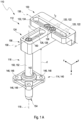
- the connecting joint comprises a horizontal bearing unit connectable to a first component of the at least two components of the laboratory automation system. Further, the connecting joint comprises a vertical bearing unit connectable to a second component of the at least two components of the laboratory automation system. Further, the connecting joint comprises a slider bar connecting the horizontal bearing unit with the vertical bearing unit. The slider bar is movably mounted along a vertical axis within the vertical bearing unit. The slider bar is adjustably mounted in the horizontal bearing unit. The slider bar is adjustable in at least one dimension essentially perpendicular to the vertical axis by the horizontal bearing unit.
- the term "laboratory” as used herein is a broad term and is to be given its ordinary and customary meaning to a person of ordinary skill in the art and is not to be limited to a special or customized meaning.
- the term specifically may refer, without limitation, to at least one environment comprising at least one instrument configured for preparing and/or analyzing at least one sample, such as a test sample, e.g. a chemical sample and/or a biological sample.
- the sample may be contained in at least one container such as a sample tube.
- the laboratory may be a location configured for work in the field of the natural sciences and/or engineering in the sense that it offers the opportunity to conduct corresponding measurements and controls.
- the term "laboratory automation system" as used herein is a broad term and is to be given its ordinary and customary meaning to a person of ordinary skill in the art and is not to be limited to a special or customized meaning.
- the term specifically may refer, without limitation, to a system which is configured for handling samples automatically.
- the laboratory automation system may be configured for processing samples, specifically samples contained in container such as sample tubes in which samples are enclosed autonomously and/or fully or partially automatically.
- the laboratory automation system may comprise at least one laboratory distribution system, such as an actuator, configured for transferring the at least one sample from one position to another position.
- the laboratory automation system may further comprise one or more handling stations for handling and/or processing one or more of the samples.
- the laboratory automation system may further comprise at least one laboratory station for sample analysis.
- a laboratory in which the laboratory automation system is used may be for example a medical laboratory such as a clinical laboratory, a forensic laboratory or a blood bank. Further, the laboratory in which the laboratory automation system is used may be a chemical laboratory, such as an analytic laboratory. Also, other applications may be feasible.
- component as used herein is a broad term and is to be given its ordinary and customary meaning to a person of ordinary skill in the art and is not to be limited to a special or customized meaning.
- the term specifically may refer, without limitation, to a part of a mechanical and/or mechatronical system.
- the component may be handled independently or may be coupled, connectable or integratable in order to fulfill at least one common function.
- first component and second component may be considered as nomenclature only, without numbering or ranking the named elements, without specifying an order and without excluding a possibility that several kinds of first components and second components may be present. Further, additional components such as one or more third components may be present.
- the first component may be a laboratory station of the laboratory automation system and the second component may be a laboratory distribution system of the laboratory automation system or vice versa.
- the first component may be the laboratory distribution system of the laboratory automation system and the second component may be the laboratory station of the laboratory automation system. Further details on the laboratory station and the laboratory distribution system are given below.
- connecting joint is a broad term and is to be given its ordinary and customary meaning to a person of ordinary skill in the art and is not to be limited to a special or customized meaning.
- the term specifically may refer, without limitation, to an arbitrary element which is configured for forming a mechanical coupling between at least two physical objects.
- at least one first physical object may be mechanically coupled to at least one second physical object via the element.
- the element may be mechanically connectable to the first physical object and the element may be mechanically connectable to the second physical object.
- the mechanical connection specifically may be selected from the group consisting of: an interlocking connection, a frictional connection, a substance-to-substance bond.
- the element may be configured for restricting a mobility between the first physical object and the second physical object.
- the connecting joint may be configured for adjustably connecting the at least two components.
- the term "configured for adjustably connecting” as used herein is a broad term and is to be given its ordinary and customary meaning to a person of ordinary skill in the art and is not to be limited to a special or customized meaning.
- the term specifically may refer, without limitation, to a property of an arbitrary joint of being configured for restricting a mobility between at least two physical objects in an adaptable matter.
- a relative position of a first physical object to the second physical object may be adaptable via the joint.
- the relative position of the first physical object to the second physical object may be changeable by a rotational movement and/or a translational movement of one of the first physical object and the second physical object relative to the other physical object via the joint.
- the joint may be configured for forming a mechanical connection to the first physical object and to the second physical object, respectively, and, thereafter, the relative position of the first physical object to the second physical object may be adjusted.
- the joint may have at least two parts which are translationally and/or rotationally moveable relative to each other.
- the connecting joint comprises the horizontal bearing unit and the vertical bearing unit.
- unit as used herein is a broad term and is to be given its ordinary and customary meaning to a person of ordinary skill in the art and is not to be limited to a special or customized meaning.
- the term specifically may refer, without limitation, to an arbitrary element being configured to interact with another element in order to fulfill at least one common function.
- the elements may be coupled to each other, connectable to each other or integratable into each other in order to form a common component.
- the unit may also be referred to as part or as component.
- bearing unit is a broad term and is to be given its ordinary and customary meaning to a person of ordinary skill in the art and is not to be limited to a special or customized meaning.
- the term specifically may refer, without limitation, to an arbitrary device or component which is configured for carrying and/or supporting at least one further device or component.
- the bearing unit specifically may be configured for constraining a relative motion between at least two physical objects to only a desired motion between the physical objects.
- the component may be configured for reducing friction between the physical objects.
- the bearing unit may be configured for preventing a motion by controlling one or more vectors of normal forces that bear on the physical objects.
- vertical bearing unit as used herein is a broad term and is to be given its ordinary and customary meaning to a person of ordinary skill in the art and is not to be limited to a special or customized meaning.
- the term specifically may refer, without limitation, to an arbitrary bearing unit which is configured for enabling a movement between at least two physical objects in a vertical axis.
- the vertical axis may correspond to an axis z and may be arranged perpendicular to the axes x and y as defined above.
- vertical axis as used herein is a broad term and is to be given its ordinary and customary meaning to a person of ordinary skill in the art and is not to be limited to a special or customized meaning.
- the term specifically may refer, without limitation, to a property of an axis of standing perpendicular to a horizontal level of a system such as the laboratory automation system, and/or to the level surfaces of the earth's gravity field in the direction of the resultant from the earth's gravitation and the centrifugal force due to the earth's rotation.
- horizontal bearing unit as used herein is a broad term and is to be given its ordinary and customary meaning to a person of ordinary skill in the art and is not to be limited to a special or customized meaning.
- the term specifically may refer, without limitation, to an arbitrary bearing unit which is configured for enabling a movement between at least two physical objects in a horizontal plane.
- the horizontal plane may exemplarily extend along an axis x and an axis y which are arranged perpendicular to each other.
- horizontal plane as used herein is a broad term and is to be given its ordinary and customary meaning to a person of ordinary skill in the art and is not to be limited to a special or customized meaning.
- the term specifically may refer, without limitation, to a plane parallel to a horizontal working surface in a system such as the laboratory automation system.
- the horizontal plane is perpendicular to the vertical axis as defined above.
- the horizontal bearing unit is connectable to the first component and the vertical bearing unit is connectable to the second component.
- the term "connectable to a component" as used herein is a broad term and is to be given its ordinary and customary meaning to a person of ordinary skill in the art and is not to be limited to a special or customized meaning.
- the term specifically may refer, without limitation, to a property of an element of being mechanically couplable to an arbitrary component.
- the element and the component may have a mechanical connection.
- the mechanical connection may be selected from the group consisting of: an interlocking connection, a frictional connection, a substance-to-substance bond. Also other embodiments may be feasible. Further details on the mechanical connection between the horizontal bearing unit and the first component and on the mechanical connection between the vertical bearing unit and the second component are given below in more detail.
- the horizontal bearing unit may be fixedly connectable to the first component of the at least two components of the laboratory automation system.
- the term "being fixedly connectable” as used herein is a broad term and is to be given its ordinary and customary meaning to a person of ordinary skill in the art and is not to be limited to a special or customized meaning.
- the term specifically may refer, without limitation, to a property of an object of being of an element of being mechanically couplable to an arbitrary component such that a movement of the element relative to the component is suppressed completely or at least to a large extent.
- the horizontal bearing unit may be fixedly connectable to the first component of the at least two components of the laboratory automation system by a force-fit connection.
- the first linear guide may have a length of 1 mm to 100 mm, preferably of 5 mm to 20 mm, most preferably of 15 mm.
- the second linear guide may have a length of 10 mm to 100 mm, preferably of 20 mm to 50 mm, preferably of 25 mm to 35 mm, most preferably of 30 mm.
- the screw 160 may be screwed down, specifically such that a relative movement of the slider bar 116 to the first part 124 may be suppressed or at least reduced to a large extent.
- the second end 156 of the slider bar 116 unit may be partially received in the first linear guide 126, specifically in the first elongated hole 128.
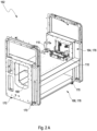
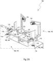
- Figures 2A and 2B show an exemplary embodiment of a laboratory automation system 162 in a perspective view ( Figure 2A ) and in a detailed view ( Figure 2B ).
- the laboratory automation system 162 comprises a plurality of laboratory stations 164. In Figures 2A and 2B one laboratory station 164 is exemplarily shown. Further, the laboratory automation system 162 comprises at least one laboratory distribution system 166. The laboratory distribution system 166 is configured to distribute laboratory cargo between the laboratory stations 164. Further, the laboratory automation system comprises at least one connecting joint 110. The connecting joint 110 connects the laboratory station 164 to the laboratory distribution system 166. The connecting joint 110 as depicted in Figures 2A and 2B corresponds to the connecting joint 110 as depicted in Figures 1A and 1B . Thus, reference to the description of Figures 1A and 1B above is made.
- the laboratory distribution system 166 may have a transport line (not shown in Figures 2A and 2B ) configured for distributing laboratory cargo to a target destination within the laboratory automation system 162. Further, the laboratory distribution system 166 may have a plurality of racks and/or drawers (not shown in Figures 2A and 2B ) for storing the laboratory cargo. In Figure 2A an opening 168 configured for receiving the laboratory cargo is shown.
- the laboratory automation system 162 comprises a plurality of adjustable feet 170 to compensate differences in height which may specifically result from a sinking of the adjustable feet 170 into the ground.
- a further improvement of a horizontal alignment may be achieved by the connecting joints 110.
- the connecting joints 110 as illustrated in Figure 2B adjustably connect the laboratory station 164, which may also be referred to as first component 176 of the laboratory automation system 162, and the laboratory distribution system 166, which may also be referred to as second component 178 of the laboratory automation system 162.
- the horizontal bearing unit 112 is connectable to the first component 176.
- the horizontal bearing unit 112 may be fixedly connectable to the first component 176 via one or more connecting elements 120, specifically one or more through holes 122.
- the horizontal bearing unit 112 may further comprise the screws 124.
- the horizontal bearing unit 112 may be configured to be screwed to the first component 176.
- the connecting joint 110 comprises the vertical bearing unit 114 connectable to the second component 178.
Landscapes
- Engineering & Computer Science (AREA)
- General Engineering & Computer Science (AREA)
- Mechanical Engineering (AREA)
- Physics & Mathematics (AREA)
- Health & Medical Sciences (AREA)
- Life Sciences & Earth Sciences (AREA)
- Chemical & Material Sciences (AREA)
- Analytical Chemistry (AREA)
- Biochemistry (AREA)
- General Health & Medical Sciences (AREA)
- General Physics & Mathematics (AREA)
- Immunology (AREA)
- Pathology (AREA)
- Automatic Analysis And Handling Materials Therefor (AREA)
- Apparatus Associated With Microorganisms And Enzymes (AREA)
Claims (15)
- Verbindungsgelenk (110) zum einstellbaren Verbinden von mindestens zwei Komponenten (176, 178) eines Laborautomatisierungssystems (162), wobei das Verbindungsgelenk (110) Folgendes umfasst:A. eine horizontale Lagereinheit (112), die fest mit einer ersten Komponente (176) von den mindestens zwei Komponenten (176, 178) des Laborautomatisierungssystems (162) verbunden werden kann;B. eine vertikale Lagereinheit (114), die fest mit einer zweiten Komponente (178) von den mindestens zwei Komponenten (176, 178) des Laborautomatisierungssystems (162) verbunden werden kann; undC. eine Gleitstange (116), die die horizontale Lagereinheit (112) mit der vertikalen Lagereinheit (114) verbindet,wobei die erste Komponente (176) eine Laborstation (164) des Laborautomatisierungssystems (162) ist und wobei die zweite Komponente (178) ein Laborverteilungssystem (166) des Laborautomatisierungssystems (162) ist oder umgekehrt.- wobei die Gleitstange (116) entlang einer vertikalen Achse (118) innerhalb der vertikalen Lagereinheit (114) beweglich montiert ist; und- wobei die Gleitstange (116) in der horizontalen Lagereinheit (112) einstellbar montiert ist, wobei die Gleitstange (116) in mindestens einer Dimension, die im Wesentlichen senkrecht zu der vertikalen Achse (118) ist, mithilfe der horizontalen Lagereinheit (112) eingestellt werden kann;
- Verbindungsgelenk (110) nach dem vorstehenden Anspruch, wobei die Gleitstange (116) entlang der vertikalen Achse (118) innerhalb der vertikalen Lagereinheit (114) verschiebbar montiert ist.
- Verbindungsgelenk (110) nach einem der vorstehenden Ansprüche, wobei die vertikale Lagereinheit (114) mindestens ein Gleitlager (140) umfasst, wobei das Gleitlager (140) mindestens eine Lagerbohrung (142) umfasst, wobei die Lagerbohrung (142) dafür ausgebildet ist, die Gleitstange (116) teilweise aufzunehmen.
- Verbindungsgelenk (110) nach dem vorstehenden Anspruch, wobei die Gleitstange (116) in der Lagerbohrung (142) des Gleitlagers (140) verschiebbar montiert ist.
- Verbindungsgelenk (110) nach einem der vorstehenden Ansprüche, wobei die Gleitstange (116) fest in einer einstellbaren Position in der mindestens einen Dimension senkrecht zu der vertikalen Achse (118) in der horizontalen Lagereinheit (112) montiert ist.
- Verbindungsgelenk (110) nach einem der vorstehenden Ansprüche, wobei die horizontale Lagereinheit (112) ein oder mehrere Verbindungselement(e) (120) zum festen Verbinden der horizontalen Lagereinheit (112) mit der ersten Komponente (176) umfasst.
- Verbindungsgelenk (110) nach einem der vorstehenden Ansprüche, wobei die horizontale Lagereinheit (112) mindestens ein erstes Teil (124) mit mindestens einer ersten linearen Führung (126) und mindestens ein zweites Teil (130) mit mindestens einer zweiten linearen Führung (132) umfasst.
- Verbindungsgelenk (110) nach dem vorstehenden Anspruch, wobei das erste Teil (124) und das zweite Teil (130) im Wesentlichen senkrecht zueinander angeordnet sind.
- Verbindungsgelenk (110) nach einem der beiden vorstehenden Ansprüche, wobei das erste Teil (124) und das zweite Teil (130) einstellbar aneinander montiert sind.
- Verbindungsgelenk (110) nach einem der drei vorstehenden Ansprüche, wobei eine Position des ersten Teils (124) in Bezug auf das zweite Teil (130) entlang einer Achse (136), die von der zweiten linearen Führung (132) definiert wird, einstellbar ist.
- Verbindungsgelenk (110) nach einem der vier vorstehenden Ansprüche, wobei eine Position der Gleitstange (116) in Bezug auf das erste Teil (124) entlang einer Achse (158), die von der ersten linearen Führung (126) definiert wird, einstellbar ist.
- Verbindungsgelenk (110) nach einem der fünf vorstehenden Ansprüche, wobei ein Ende (156) der Gleitstangeneinheit (116) teilweise in der ersten linearen Führung (126) aufgenommen ist.
- Laborautomatisierungssystem (162), umfassend:• eine Vielzahl von Laborstationen (164);• mindestens ein Laborverteilungssystem (166), wobei das Laborverteilungssystem (166) dafür ausgebildet ist, Labortransportgut zwischen den Laborstationen (164) zu verteilen; und• mindestens ein Verbindungsgelenk (110) nach einem der vorstehenden Ansprüche, wobei das Verbindungsgelenk (110) mindestens eine der Laborstationen (164) mit dem Laborverteilungssystem (166) verbindet.
- Laborautomatisierungssystem (162) nach dem vorstehenden Anspruch, wobei eine der Laborstationen (164) über mindestens zwei der Verbindungsgelenke (110) mit dem Laborverteilungssystem (166) verbunden ist.
- Verfahren zum einstellbaren Verbinden von mindestens zwei Komponenten (176, 178) eines Laborautomatisierungssystems (162), wobei das Verfahren die folgenden Schritte umfasst:i. Bereitstellen mindestens eines Verbindungsgelenkes (110) nach einem der vorstehenden Ansprüche, die sich auf ein Verbindungsgelenk (110) beziehen;ii. festes Verbinden der horizontalen Lagereinheit (112) mit der ersten Komponente (176) von den mindestens zwei Komponenten (176, 178) des Laborautomatisierungssystems (162) undiii. festes Verbinden der vertikalen Lagereinheit (114) mit der zweiten Komponente (178) von den mindestens zwei Komponenten (176, 178) des Laborautomatisierungssystems (162).
Priority Applications (4)
| Application Number | Priority Date | Filing Date | Title |
|---|---|---|---|
| EP20216535.3A EP4019822B1 (de) | 2020-12-22 | 2020-12-22 | Verbindungsgelenk zur verbindung von komponenten eines laborautomatisierungssystems |
| US17/453,977 US12092150B2 (en) | 2020-12-22 | 2021-11-08 | Connecting joint for connecting components of a laboratory automation system |
| JP2021206776A JP7297045B2 (ja) | 2020-12-22 | 2021-12-21 | ラボラトリオートメーションシステムのコンポーネントを接続するための接続ジョイント |
| CN202111575670.2A CN114658728B (zh) | 2020-12-22 | 2021-12-21 | 用于连接实验室自动化系统的部件的连接接头 |
Applications Claiming Priority (1)
| Application Number | Priority Date | Filing Date | Title |
|---|---|---|---|
| EP20216535.3A EP4019822B1 (de) | 2020-12-22 | 2020-12-22 | Verbindungsgelenk zur verbindung von komponenten eines laborautomatisierungssystems |
Publications (2)
| Publication Number | Publication Date |
|---|---|
| EP4019822A1 EP4019822A1 (de) | 2022-06-29 |
| EP4019822B1 true EP4019822B1 (de) | 2025-06-25 |
Family
ID=73856837
Family Applications (1)
| Application Number | Title | Priority Date | Filing Date |
|---|---|---|---|
| EP20216535.3A Active EP4019822B1 (de) | 2020-12-22 | 2020-12-22 | Verbindungsgelenk zur verbindung von komponenten eines laborautomatisierungssystems |
Country Status (4)
| Country | Link |
|---|---|
| US (1) | US12092150B2 (de) |
| EP (1) | EP4019822B1 (de) |
| JP (1) | JP7297045B2 (de) |
| CN (1) | CN114658728B (de) |
Families Citing this family (1)
| Publication number | Priority date | Publication date | Assignee | Title |
|---|---|---|---|---|
| FI131003B1 (en) | 2023-05-12 | 2024-07-29 | Thermo Fisher Scientific Oy | Cadence deviator for specimen carriers and method for cadencing specimen carriers |
Citations (1)
| Publication number | Priority date | Publication date | Assignee | Title |
|---|---|---|---|---|
| US20090004056A1 (en) * | 2007-06-26 | 2009-01-01 | Dade Behring Inc. | Clinical Sample Analysis System Having An Analyzer Positioning Mechanism |
Family Cites Families (28)
| Publication number | Priority date | Publication date | Assignee | Title |
|---|---|---|---|---|
| FR1530476A (fr) | 1967-04-13 | 1968-06-28 | Comp Generale Electricite | Dispositif de support et de centrage d'éléments optiques |
| JPS5620037Y2 (de) * | 1977-08-12 | 1981-05-13 | ||
| DE2907099C2 (de) | 1979-02-23 | 1980-12-11 | Fa. Carl Zeiss, 7920 Heidenheim | Vorrichtung zur Feineinstellung eines auf einer Basis angeordneten Instrumentes in allen drei Raumrichtungen |
| DE3615942A1 (de) * | 1986-05-12 | 1987-11-19 | Ekkehard Ueberreiter | Vorrichtung zum kraftarmen handhaben und moeglichst genauem positionieren eines schweren elektronischen testgeraetes, insbesondere eines testcomputers |
| DE3813477C1 (en) | 1988-04-21 | 1989-11-23 | Ekkehard 8201 Raubling De Ueberreiter | Apparatus for holding an object |
| IT1260447B (it) * | 1992-01-27 | 1996-04-09 | Procedimento e apparecchiatura per l'automazione integrale di un laboratorio di analisi | |
| JP3328000B2 (ja) * | 1992-06-11 | 2002-09-24 | 株式会社アマダ | 二次元運動装置 |
| DE60030957T2 (de) * | 1999-02-16 | 2007-06-14 | Applera Corp., Foster City | Kugelabgabesystem |
| EP1208511A4 (de) | 1999-08-13 | 2003-02-05 | Trilegiant Corp | Transaktionsbasierte belohnung |
| JP3498659B2 (ja) * | 1999-12-09 | 2004-02-16 | 松下電器産業株式会社 | 高さ固定装置 |
| AU2003241450A1 (en) * | 2002-05-13 | 2003-12-02 | Scinomix | Automated processing system and method of using same |
| JP2007209861A (ja) | 2006-02-07 | 2007-08-23 | Yamanaka:Kk | 実験台用天板 |
| TWI439709B (zh) * | 2006-12-29 | 2014-06-01 | Intest Corp | 用於使負載沿平移軸線平移之操縱器與負載定位系統 |
| DE102007051918A1 (de) * | 2007-10-29 | 2009-04-30 | Little Things Factory Gmbh | Stirnseitiges Anschlusssystem für platteförmige Mikrokomponente |
| CN102034557B (zh) * | 2009-09-30 | 2013-03-27 | 北京谊安医疗系统股份有限公司 | 一种控制水平旋转并定位的装置 |
| DE102010028769A1 (de) | 2010-05-07 | 2011-11-10 | Pvt Probenverteiltechnik Gmbh | System zum Transportieren von Behältern zwischen unterschiedlichen Stationen und Behälterträger |
| DE102013200500B4 (de) * | 2013-01-15 | 2017-09-21 | Siemens Healthcare Gmbh | Einstellvorrichtung, sowie eine Magnetresonanzvorrichtung mit einer Einstellvorrichtung |
| EP3056320B1 (de) * | 2015-02-10 | 2018-12-05 | F. Hoffmann-La Roche AG | Robotervorrichtung und Automatisierungssystem mit Robotervorrichtung |
| CN204570073U (zh) * | 2015-04-17 | 2015-08-19 | 中国石油大学(华东) | 实验室用水浴温控式渡槽 |
| EP3196652A1 (de) | 2016-01-22 | 2017-07-26 | Roche Diagnostics GmbH | Laborverteilungssystem |
| CN106695232B (zh) * | 2017-01-19 | 2018-03-06 | 太平洋纺织机械(常熟)有限公司 | 玻璃模具自动焊接机的玻璃模具夹装定位装置 |
| CN206450721U (zh) * | 2017-02-08 | 2017-08-29 | 深圳市燕麦科技股份有限公司 | 一种双平台连接机构 |
| CN208169972U (zh) * | 2018-03-26 | 2018-11-30 | 广州市珠江灯光科技有限公司 | 活动架软连接结构 |
| CN109102842B (zh) | 2018-09-07 | 2023-09-12 | 河南中光学集团有限公司 | 一种二维平面平移调整装置 |
| EP3633384B1 (de) | 2018-10-04 | 2020-12-09 | Tecan Trading AG | Schlauchführung für ein laborautomatisierungssystem |
| CN209635872U (zh) * | 2018-11-27 | 2019-11-15 | 无锡书谱尔精密机械科技有限公司 | 灌装机 |
| CN209458230U (zh) * | 2019-01-25 | 2019-10-01 | 河北九晟建材科技有限公司 | 一种新型管连接件 |
| IT201900024574A1 (it) * | 2019-12-18 | 2021-06-18 | Inpeco Holding Ltd | Apparato di automazione di laboratorio di analisi |
-
2020
- 2020-12-22 EP EP20216535.3A patent/EP4019822B1/de active Active
-
2021
- 2021-11-08 US US17/453,977 patent/US12092150B2/en active Active
- 2021-12-21 JP JP2021206776A patent/JP7297045B2/ja active Active
- 2021-12-21 CN CN202111575670.2A patent/CN114658728B/zh active Active
Patent Citations (1)
| Publication number | Priority date | Publication date | Assignee | Title |
|---|---|---|---|---|
| US20090004056A1 (en) * | 2007-06-26 | 2009-01-01 | Dade Behring Inc. | Clinical Sample Analysis System Having An Analyzer Positioning Mechanism |
Also Published As
| Publication number | Publication date |
|---|---|
| JP7297045B2 (ja) | 2023-06-23 |
| CN114658728B (zh) | 2025-03-11 |
| JP2022099308A (ja) | 2022-07-04 |
| EP4019822A1 (de) | 2022-06-29 |
| US12092150B2 (en) | 2024-09-17 |
| US20220196052A1 (en) | 2022-06-23 |
| CN114658728A (zh) | 2022-06-24 |
Similar Documents
| Publication | Publication Date | Title |
|---|---|---|
| EP2845014B1 (de) | Gelenkige probenbehältergestellvorrichtung, gestellfördersysteme und verfahren zum fördern von probenbehältern | |
| US8142719B2 (en) | Analysis device | |
| CN103042531B (zh) | 用于抓握及保持诊断盒的装置 | |
| US20060257999A1 (en) | Compound profiling devices, systems, and related methods | |
| EP2232272B1 (de) | Automatisches beladen von probenröhrchen für klinisches analysegerät | |
| US5738827A (en) | Apparatus for holding reagent and sample vessels | |
| EP2773965B1 (de) | Multiküvetten-autosampler für photooptische messungen | |
| US20060028802A1 (en) | Object storage devices, systems, and related methods | |
| US9823264B2 (en) | Transfer or interrogation of materials by carrier and receiving devices moving independently and simultaneously on multiple axes | |
| JP2007524842A (ja) | アッセイ試験診断分析装置 | |
| CN107179414B (zh) | 用于混合自动分析仪中液体的方法 | |
| US12092150B2 (en) | Connecting joint for connecting components of a laboratory automation system | |
| JP6619133B2 (ja) | 分析装置の設置 | |
| JP6362737B2 (ja) | 自動分析装置における液体コンテナの輸送 | |
| US20190314813A1 (en) | A point-of-care diagnostic assay cartridge | |
| WO2018077983A1 (en) | A point-of-care diagnostic assay cartridge | |
| WO2018017753A1 (en) | Puck top tube carrier construction | |
| CN106908617B (zh) | 在分析仪中转移液体体积的方法 | |
| WO2004051414A2 (en) | Wave guide with isolated coupling interface | |
| EP4147781A1 (de) | Zentrierhalter zum zentrieren eines probenröhrchens | |
| JP2020201257A (ja) | いくつかの平面内に試薬コンテナを収納する装置 | |
| AU2007234480A1 (en) | Automated centrifuge and method of using same |
Legal Events
| Date | Code | Title | Description |
|---|---|---|---|
| PUAI | Public reference made under article 153(3) epc to a published international application that has entered the european phase |
Free format text: ORIGINAL CODE: 0009012 |
|
| STAA | Information on the status of an ep patent application or granted ep patent |
Free format text: STATUS: THE APPLICATION HAS BEEN PUBLISHED |
|
| AK | Designated contracting states |
Kind code of ref document: A1 Designated state(s): AL AT BE BG CH CY CZ DE DK EE ES FI FR GB GR HR HU IE IS IT LI LT LU LV MC MK MT NL NO PL PT RO RS SE SI SK SM TR |
|
| STAA | Information on the status of an ep patent application or granted ep patent |
Free format text: STATUS: REQUEST FOR EXAMINATION WAS MADE |
|
| 17P | Request for examination filed |
Effective date: 20221209 |
|
| RBV | Designated contracting states (corrected) |
Designated state(s): AL AT BE BG CH CY CZ DE DK EE ES FI FR GB GR HR HU IE IS IT LI LT LU LV MC MK MT NL NO PL PT RO RS SE SI SK SM TR |
|
| REG | Reference to a national code |
Ref country code: DE Ref legal event code: R079 Free format text: PREVIOUS MAIN CLASS: F16M0011200000 Ipc: G01N0035000000 Ref country code: DE Ref legal event code: R079 Ref document number: 602020053238 Country of ref document: DE Free format text: PREVIOUS MAIN CLASS: F16M0011200000 Ipc: G01N0035000000 |
|
| GRAP | Despatch of communication of intention to grant a patent |
Free format text: ORIGINAL CODE: EPIDOSNIGR1 |
|
| STAA | Information on the status of an ep patent application or granted ep patent |
Free format text: STATUS: GRANT OF PATENT IS INTENDED |
|
| RIC1 | Information provided on ipc code assigned before grant |
Ipc: G12B 5/00 20060101ALI20241011BHEP Ipc: F16M 11/20 20060101ALI20241011BHEP Ipc: F16M 11/04 20060101ALI20241011BHEP Ipc: F16M 13/02 20060101ALI20241011BHEP Ipc: G01N 35/00 20060101AFI20241011BHEP |
|
| INTG | Intention to grant announced |
Effective date: 20241025 |
|
| GRAJ | Information related to disapproval of communication of intention to grant by the applicant or resumption of examination proceedings by the epo deleted |
Free format text: ORIGINAL CODE: EPIDOSDIGR1 |
|
| STAA | Information on the status of an ep patent application or granted ep patent |
Free format text: STATUS: REQUEST FOR EXAMINATION WAS MADE |
|
| INTC | Intention to grant announced (deleted) | ||
| RIN1 | Information on inventor provided before grant (corrected) |
Inventor name: ADDIHALLI NARAYANA, AVINASH Inventor name: GUTMANN, TIMO Inventor name: APODACA LUJAN, LEON FELIPE Inventor name: MEYER, THOMAS Inventor name: LUSSER, EUGEN |
|
| GRAP | Despatch of communication of intention to grant a patent |
Free format text: ORIGINAL CODE: EPIDOSNIGR1 |
|
| STAA | Information on the status of an ep patent application or granted ep patent |
Free format text: STATUS: GRANT OF PATENT IS INTENDED |
|
| INTG | Intention to grant announced |
Effective date: 20250116 |
|
| GRAS | Grant fee paid |
Free format text: ORIGINAL CODE: EPIDOSNIGR3 |
|
| GRAA | (expected) grant |
Free format text: ORIGINAL CODE: 0009210 |
|
| STAA | Information on the status of an ep patent application or granted ep patent |
Free format text: STATUS: THE PATENT HAS BEEN GRANTED |
|
| AK | Designated contracting states |
Kind code of ref document: B1 Designated state(s): AL AT BE BG CH CY CZ DE DK EE ES FI FR GB GR HR HU IE IS IT LI LT LU LV MC MK MT NL NO PL PT RO RS SE SI SK SM TR |
|
| REG | Reference to a national code |
Ref country code: GB Ref legal event code: FG4D |
|
| REG | Reference to a national code |
Ref country code: CH Ref legal event code: EP |
|
| REG | Reference to a national code |
Ref country code: CH Ref legal event code: EP |
|
| REG | Reference to a national code |
Ref country code: IE Ref legal event code: FG4D |
|
| REG | Reference to a national code |
Ref country code: DE Ref legal event code: R096 Ref document number: 602020053238 Country of ref document: DE |
|
| PG25 | Lapsed in a contracting state [announced via postgrant information from national office to epo] |
Ref country code: FI Free format text: LAPSE BECAUSE OF FAILURE TO SUBMIT A TRANSLATION OF THE DESCRIPTION OR TO PAY THE FEE WITHIN THE PRESCRIBED TIME-LIMIT Effective date: 20250625 |
|
| REG | Reference to a national code |
Ref country code: LT Ref legal event code: MG9D |
|
| PG25 | Lapsed in a contracting state [announced via postgrant information from national office to epo] |
Ref country code: NO Free format text: LAPSE BECAUSE OF FAILURE TO SUBMIT A TRANSLATION OF THE DESCRIPTION OR TO PAY THE FEE WITHIN THE PRESCRIBED TIME-LIMIT Effective date: 20250925 Ref country code: GR Free format text: LAPSE BECAUSE OF FAILURE TO SUBMIT A TRANSLATION OF THE DESCRIPTION OR TO PAY THE FEE WITHIN THE PRESCRIBED TIME-LIMIT Effective date: 20250926 |
|
| PG25 | Lapsed in a contracting state [announced via postgrant information from national office to epo] |
Ref country code: BG Free format text: LAPSE BECAUSE OF FAILURE TO SUBMIT A TRANSLATION OF THE DESCRIPTION OR TO PAY THE FEE WITHIN THE PRESCRIBED TIME-LIMIT Effective date: 20250625 |
|
| PG25 | Lapsed in a contracting state [announced via postgrant information from national office to epo] |
Ref country code: HR Free format text: LAPSE BECAUSE OF FAILURE TO SUBMIT A TRANSLATION OF THE DESCRIPTION OR TO PAY THE FEE WITHIN THE PRESCRIBED TIME-LIMIT Effective date: 20250625 |
|
| PG25 | Lapsed in a contracting state [announced via postgrant information from national office to epo] |
Ref country code: RS Free format text: LAPSE BECAUSE OF FAILURE TO SUBMIT A TRANSLATION OF THE DESCRIPTION OR TO PAY THE FEE WITHIN THE PRESCRIBED TIME-LIMIT Effective date: 20250925 |
|
| PG25 | Lapsed in a contracting state [announced via postgrant information from national office to epo] |
Ref country code: LV Free format text: LAPSE BECAUSE OF FAILURE TO SUBMIT A TRANSLATION OF THE DESCRIPTION OR TO PAY THE FEE WITHIN THE PRESCRIBED TIME-LIMIT Effective date: 20250625 |
|
| REG | Reference to a national code |
Ref country code: NL Ref legal event code: MP Effective date: 20250625 |
|
| PG25 | Lapsed in a contracting state [announced via postgrant information from national office to epo] |
Ref country code: NL Free format text: LAPSE BECAUSE OF FAILURE TO SUBMIT A TRANSLATION OF THE DESCRIPTION OR TO PAY THE FEE WITHIN THE PRESCRIBED TIME-LIMIT Effective date: 20250625 |
|
| PG25 | Lapsed in a contracting state [announced via postgrant information from national office to epo] |
Ref country code: PT Free format text: LAPSE BECAUSE OF FAILURE TO SUBMIT A TRANSLATION OF THE DESCRIPTION OR TO PAY THE FEE WITHIN THE PRESCRIBED TIME-LIMIT Effective date: 20251027 |
|
| REG | Reference to a national code |
Ref country code: AT Ref legal event code: MK05 Ref document number: 1806958 Country of ref document: AT Kind code of ref document: T Effective date: 20250625 |
|
| PG25 | Lapsed in a contracting state [announced via postgrant information from national office to epo] |
Ref country code: IS Free format text: LAPSE BECAUSE OF FAILURE TO SUBMIT A TRANSLATION OF THE DESCRIPTION OR TO PAY THE FEE WITHIN THE PRESCRIBED TIME-LIMIT Effective date: 20251025 |
|
| PGFP | Annual fee paid to national office [announced via postgrant information from national office to epo] |
Ref country code: DE Payment date: 20251126 Year of fee payment: 6 |
|
| PGFP | Annual fee paid to national office [announced via postgrant information from national office to epo] |
Ref country code: GB Payment date: 20251119 Year of fee payment: 6 |
|
| PG25 | Lapsed in a contracting state [announced via postgrant information from national office to epo] |
Ref country code: AT Free format text: LAPSE BECAUSE OF FAILURE TO SUBMIT A TRANSLATION OF THE DESCRIPTION OR TO PAY THE FEE WITHIN THE PRESCRIBED TIME-LIMIT Effective date: 20250625 Ref country code: SM Free format text: LAPSE BECAUSE OF FAILURE TO SUBMIT A TRANSLATION OF THE DESCRIPTION OR TO PAY THE FEE WITHIN THE PRESCRIBED TIME-LIMIT Effective date: 20250625 |
|
| PGFP | Annual fee paid to national office [announced via postgrant information from national office to epo] |
Ref country code: FR Payment date: 20251120 Year of fee payment: 6 |
|
| PG25 | Lapsed in a contracting state [announced via postgrant information from national office to epo] |
Ref country code: CZ Free format text: LAPSE BECAUSE OF FAILURE TO SUBMIT A TRANSLATION OF THE DESCRIPTION OR TO PAY THE FEE WITHIN THE PRESCRIBED TIME-LIMIT Effective date: 20250625 |
|
| PG25 | Lapsed in a contracting state [announced via postgrant information from national office to epo] |
Ref country code: PL Free format text: LAPSE BECAUSE OF FAILURE TO SUBMIT A TRANSLATION OF THE DESCRIPTION OR TO PAY THE FEE WITHIN THE PRESCRIBED TIME-LIMIT Effective date: 20250625 |
|
| PG25 | Lapsed in a contracting state [announced via postgrant information from national office to epo] |
Ref country code: EE Free format text: LAPSE BECAUSE OF FAILURE TO SUBMIT A TRANSLATION OF THE DESCRIPTION OR TO PAY THE FEE WITHIN THE PRESCRIBED TIME-LIMIT Effective date: 20250625 |
|
| PG25 | Lapsed in a contracting state [announced via postgrant information from national office to epo] |
Ref country code: SK Free format text: LAPSE BECAUSE OF FAILURE TO SUBMIT A TRANSLATION OF THE DESCRIPTION OR TO PAY THE FEE WITHIN THE PRESCRIBED TIME-LIMIT Effective date: 20250625 |
|
| PG25 | Lapsed in a contracting state [announced via postgrant information from national office to epo] |
Ref country code: ES Free format text: LAPSE BECAUSE OF FAILURE TO SUBMIT A TRANSLATION OF THE DESCRIPTION OR TO PAY THE FEE WITHIN THE PRESCRIBED TIME-LIMIT Effective date: 20250625 |
|
| PG25 | Lapsed in a contracting state [announced via postgrant information from national office to epo] |
Ref country code: RO Free format text: LAPSE BECAUSE OF FAILURE TO SUBMIT A TRANSLATION OF THE DESCRIPTION OR TO PAY THE FEE WITHIN THE PRESCRIBED TIME-LIMIT Effective date: 20250625 |