EP4018992B1 - Tablettenausgabemaschine - Google Patents
Tablettenausgabemaschine Download PDFInfo
- Publication number
- EP4018992B1 EP4018992B1 EP20854357.9A EP20854357A EP4018992B1 EP 4018992 B1 EP4018992 B1 EP 4018992B1 EP 20854357 A EP20854357 A EP 20854357A EP 4018992 B1 EP4018992 B1 EP 4018992B1
- Authority
- EP
- European Patent Office
- Prior art keywords
- tablet
- tablets
- storage portions
- feeders
- feeder storage
- Prior art date
- Legal status (The legal status is an assumption and is not a legal conclusion. Google has not performed a legal analysis and makes no representation as to the accuracy of the status listed.)
- Active
Links
Images


Classifications
-
- B—PERFORMING OPERATIONS; TRANSPORTING
- B65—CONVEYING; PACKING; STORING; HANDLING THIN OR FILAMENTARY MATERIAL
- B65B—MACHINES, APPARATUS OR DEVICES FOR, OR METHODS OF, PACKAGING ARTICLES OR MATERIALS; UNPACKING
- B65B5/00—Packaging individual articles in containers or receptacles, e.g. bags, sacks, boxes, cartons, cans, jars
- B65B5/10—Filling containers or receptacles progressively or in stages by introducing successive articles, or layers of articles
- B65B5/101—Filling containers or receptacles progressively or in stages by introducing successive articles, or layers of articles by gravity
- B65B5/103—Filling containers or receptacles progressively or in stages by introducing successive articles, or layers of articles by gravity for packaging pills or tablets
-
- A—HUMAN NECESSITIES
- A61—MEDICAL OR VETERINARY SCIENCE; HYGIENE
- A61J—CONTAINERS SPECIALLY ADAPTED FOR MEDICAL OR PHARMACEUTICAL PURPOSES; DEVICES OR METHODS SPECIALLY ADAPTED FOR BRINGING PHARMACEUTICAL PRODUCTS INTO PARTICULAR PHYSICAL OR ADMINISTERING FORMS; DEVICES FOR ADMINISTERING FOOD OR MEDICINES ORALLY; BABY COMFORTERS; DEVICES FOR RECEIVING SPITTLE
- A61J7/00—Devices for administering medicines orally, e.g. spoons; Pill counting devices; Arrangements for time indication or reminder for taking medicine
- A61J7/0076—Medicament distribution means
-
- B—PERFORMING OPERATIONS; TRANSPORTING
- B65—CONVEYING; PACKING; STORING; HANDLING THIN OR FILAMENTARY MATERIAL
- B65B—MACHINES, APPARATUS OR DEVICES FOR, OR METHODS OF, PACKAGING ARTICLES OR MATERIALS; UNPACKING
- B65B35/00—Supplying, feeding, arranging or orientating articles to be packaged
- B65B35/10—Feeding, e.g. conveying, single articles
-
- B—PERFORMING OPERATIONS; TRANSPORTING
- B65—CONVEYING; PACKING; STORING; HANDLING THIN OR FILAMENTARY MATERIAL
- B65B—MACHINES, APPARATUS OR DEVICES FOR, OR METHODS OF, PACKAGING ARTICLES OR MATERIALS; UNPACKING
- B65B37/00—Supplying or feeding fluent-solid, plastic, or liquid material, or loose masses of small articles, to be packaged
- B65B37/16—Separating measured quantities from supply
-
- B—PERFORMING OPERATIONS; TRANSPORTING
- B65—CONVEYING; PACKING; STORING; HANDLING THIN OR FILAMENTARY MATERIAL
- B65B—MACHINES, APPARATUS OR DEVICES FOR, OR METHODS OF, PACKAGING ARTICLES OR MATERIALS; UNPACKING
- B65B59/00—Arrangements to enable machines to handle articles of different sizes, to produce packages of different sizes, to vary the contents of packages, to handle different types of packaging material, or to give access for cleaning or maintenance purposes
- B65B59/04—Machines constructed with readily-detachable units or assemblies, e.g. to facilitate maintenance
-
- B—PERFORMING OPERATIONS; TRANSPORTING
- B65—CONVEYING; PACKING; STORING; HANDLING THIN OR FILAMENTARY MATERIAL
- B65B—MACHINES, APPARATUS OR DEVICES FOR, OR METHODS OF, PACKAGING ARTICLES OR MATERIALS; UNPACKING
- B65B65/00—Details peculiar to packaging machines and not otherwise provided for; Arrangements of such details
- B65B65/08—Devices for counting or registering the number of articles handled, or the number of packages produced by the machine
-
- G—PHYSICS
- G07—CHECKING-DEVICES
- G07F—COIN-FREED OR LIKE APPARATUS
- G07F11/00—Coin-freed apparatus for dispensing, or the like, discrete articles
- G07F11/46—Coin-freed apparatus for dispensing, or the like, discrete articles from movable storage containers or supports
- G07F11/60—Coin-freed apparatus for dispensing, or the like, discrete articles from movable storage containers or supports the storage containers or supports being rectilinearly movable
-
- G—PHYSICS
- G07—CHECKING-DEVICES
- G07F—COIN-FREED OR LIKE APPARATUS
- G07F17/00—Coin-freed apparatus for hiring articles; Coin-freed facilities or services
- G07F17/0092—Coin-freed apparatus for hiring articles; Coin-freed facilities or services for assembling and dispensing of pharmaceutical articles
Definitions
- the present invention relates to a tablet dispensing apparatus operable to collect tablets dropped and discharged from tablet feeders, which are configured to store a large number of tablets and sequentially discharge the tablets, and separately pack the tablets using a packing device.
- the present invention relates in particular to a tablet dispensing apparatus configured to three-dimensionally hold tablet feeders in a medicine storage portion and allow the tablet feeders to be drawn forward out of the medicine storage portion.
- a tablet dispensing apparatus basically includes: a medicine storage portion configured to store a large number of tablet feeders and an upper tablet collecting portion configured to guide and allow tablets discharged from the tablet feeders to be dropped downward; a lower tablet collecting portion located below the medicine storage portion and configured to collect and allow the dropped tablets to be dropped downward; a packing device located below the lower tablet collecting portion and configured to input the dropped tablets into separated housing portions of a dispensing band and thereafter seal opening portions of the housing portions; and a controller (control device) formed from a microprocessor system etc.
- the large number of tablet feeders are held in the medicine storage portion in a cubic shape in line in the up-down direction (vertical direction), the left-right direction (lateral direction), and the front-rear direction (depth direction).
- at least a plurality of tablet feeders arranged in line in the front-rear direction can be drawn forward together out of the medicine storage portion.
- a tablet dispensing apparatus is disclosed in US 7 293 672 B2 describing cassette magazines each comprising shelfs each housing several cassettes.
- Each magazine comprises a plurality of tablet feeder storage portions configured to store a plurality of tablet feeders and disposed in line in a vertical direction.
- Each magazine includes a component defining a tablet falling path for the tablets from the tablet feeders.
- tablet dispensing apparatuses according to the related art are also equipped with a manual tablet dispenser. Further, even tablet dispensing apparatuses according to the related art that are not equipped with a manual tablet dispenser secure an equipment space for possible addition of a manual tablet dispenser.
- the manual tablet dispenser is basically used to manually put tablets that are not present in the medicine storage portion into a large number of sectioned chambers. Therefore, the manual tablet dispenser is equipped with a fixed or removable manual dispensing unit in which a large number of sectioned chambers to which the tablets are to be manually dispensed are disposed in the front-rear and left-right directions, and a sequential discharge mechanism portion operable to allow the tablets to be dropped downward by opening the bottom of the sectioned chambers, usually one chamber at a time.
- the tablet feeders of the multiple tablet-compatible type do not require cassette replacement or use of different cassettes even if the types or the shapes of tablets are different to a certain degree, and thus can be highly used in common.
- the tablet feeders of this type are complicated in structure, and therefore it is difficult to increase the quantity of tablets to be stored.
- a tablet cassette is rendered removable, in addition, the quantity of tablets to be stored may be further sacrificed. Therefore, most tablet feeders of the multiple tablet-compatible type are of a fixed cassette type, and used as incorporated in a part of the medicine storage portion.
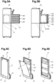
- a tablet dispensing apparatus includes: a plurality of tablet feeder storage portions 20A to 20C configured to store a plurality of tablet feeders 52 and disposed in line in a vertical direction; an upper tablet collecting portion 30 disposed along the plurality of tablet feeder storage portions 20A to 20C and including a tablet falling path that guides and allows tablets to be dropped downward from the plurality of tablet feeder storage portions 20A to 20C; a medicine storage portion 13 configured to house at least the plurality of tablet feeder storage portions 20A to 20C and the upper tablet collecting portion 30; and a lower tablet collecting portion 16 disposed below the upper tablet collecting portion 30 and configured to guide the tablets dropped from the upper tablet collecting portion 30 to a dispensing portion.
- the tablet dispensing apparatus also includes a plurality of storage portion sliding mechanisms 22 configured to support the plurality of tablet feeder storage portions 20A to 20C to be individually slidable forward; and a collecting portion sliding mechanism 37 configured to support the upper tablet collecting portion 30 to be slidable forward independently of the plurality of tablet feeder storage portions 20A to 20C.
- a plurality of tablet feeders 52 of a multiple tablet-compatible type are disposed in the tablet feeder storage portions 20A to 20C which occupy a part of the medicine storage portion 13.
- the upper tablet collecting portion 30 is also provided as hidden behind a front panel 25, to be discussed later, of the tablet feeder storage portions 20A to 20C.
- a grip 33 provided on the front surface of the upper tablet collecting portion 30 is also hidden behind the front panel 25.
- the upper tablet collecting portion 30 leads tablets discharged from the tablet feeders 52 of the tablet feeder storage portions 20A to 20C to the lower tablet collecting mechanism 16A which is provided therebelow.
- the upper tablet collecting portion 30 receives tablets discharged from the tablet feeders 52, of the multiple tablet-compatible type, in the tablet feeder storage portions 20A to 20C.
- a funnel-shaped receiving portion 17a is provided under each of the standard upper tablet collecting portions 17, and a funnel-shaped receiving portion 30a that is smaller than the receiving portion 17a is provided under the upper tablet collecting portion 30.
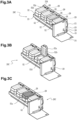
- the lid 52a When the front end portion of the lid 52a is pulled down using a finger etc., the lid 52a is turned toward the lower front (lower left in Fig. 4 ) to be horizontal to close the upper surface of the container portion 52c [see Fig. 4B ].
- the lid open-close state detecting means 29 is mainly formed from a magnetic sensor, for example, and provided in the back plate portion 23A of the shelf 23 as with the light emitting device 26, and located in rear of the corresponding tablet feeder 52 to detect whether the corresponding lid 52a is in an opened state or a closed state. It is possible to detect whether the lid 52a is in an opened state or a closed state by fixing a permanent magnet or a magnetic substance to the lid 52a and detecting variations in the distance from the permanent magnet or the magnetic substance using the magnetic sensor.
- the lid open-close state detecting means 29 is configured to detect not only whether or not the lid 52a is opened enough to allow input of tablets, but also whether or not the lid 52a is closed enough to prevent overflow of tablets.
- the opened state of the lid 52a can be detected based on the difference in output values from a plurality of magnetic sensors with different sensitivity levels by providing such magnetic sensors in the back plate portion 23A.
- the opened state of the lid 52a can also be detected through a comparison between an output value from a single magnetic sensor and a plurality of thresholds at different levels.
- the result of the detection by the lid open-close state detecting means 29 is transferred to the control system CS which has a function of managing input of tablets.
- the control system CS determines that input of tablets to the corresponding tablet feeder 52 has been started.
- the lid open-close state detecting means 29 determines that input of tablets to the corresponding tablet feeder 52 has been started.
- the manual lock 43 is provided on the front panel 25 of the tablet feeder storage portions 20A to 20C, as discussed already.
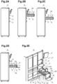
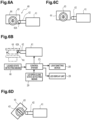
- Figs. 6A to 6D each illustrates the draw-out locking mechanism 40 including the manual lock 43.
- the draw-out locking mechanism 40 includes an electric lock operating mechanism (41, 42, 44) that is electrically operable and a manual lock operating mechanism (43, 44) that is manually operable.
- an electromagnetic drive portion 41 that constitutes a main portion of the electric lock operating mechanism is mounted to the medicine storage portion 13, and the manual lock 43 and a turning member 44 that constitute a main portion of the manual lock operating mechanism are mounted to the tablet feeder storage portions 20A to 20C.
- the tablet feeder storage portion (20A to 20C) which has been drawn out forward is pushed into the medicine storage portion 13
- the turning member 44 temporarily retracts the advancing-retracting member 42 to move the advancing-retracting member 42 rearward [see the dash-double-dot line and the dot and dash line in Fig. 6B ].
- the tablet feeder storage portions 20A to 20C can be pushed in at any time, while draw-out of the tablet feeder storage portions 20A to 20C is normally locked except when an unlocking command is provided from the control system CS.
- the control system CS issues an alarm also under the following conditions.
- the conditions are that the locked state detecting means 46 discussed above detects that the relevant tablet feeder storage portion (20A to 20C) is located within a range in which the draw-out locking mechanism 40 can be locked and that the lid open-close state detecting means 29 does not detect that the lids 52a are closed enough to prevent overflow of tablets [see Figs. 3B and 3C ].
- this alarm is issued more distinctly than the alarm discussed above issued when the lids are halfway closed, in order to reliably remind the worker.
- the tablet feeder storages 14 and the tablet feeder storage portions 20A to 20C are housed in the housing 19 of the tablet dispensing apparatus 10 and brought into a stand-by state [see Figs. 1 and 2A ], the tablet feeder storages 14 are retained in the housing 19 by a locking mechanism (see Fig. 5 of Patent Document 4, for example), the tablet feeder storage portions 20A to 20C are retained in the housing 19 by the relevant draw-out locking mechanism 40 [see Fig. 6A ], and the upper tablet collecting portion 30 is retained in the housing 19 by the front panel 25 of the tablet feeder storage portions 20A to 20C (see Fig. 1 ).
- the touch screen 15 is externally mounted to the medicine storage portion 13 to be easily changeable in position and posture, and thus work is preferably performed while manually moving the touch screen 15 to an easily seeable and operable position and changing the direction thereof. Repeated description will be omitted hereinafter.
- the lid 52a When the appropriate lid 52a is opened wide enough, that is, the lid 52a is opened enough to allow input of tablets, the lid 52a being opened is detected by the lid open-close state detecting means 29, and the light emitting device 26 is turned off under control by the control system CS which has received the detection result [see Fig. 3B ]. Therefore, the lid 52a is not dazzling any more, and the inside of the container portion 52c is easily seeable.
- the worker turns the foremost movable rack 24 forward into a horizontal orientation for the tablet feeder storage portion 20C which has been drawn out and the other tablet feeder storage portions 20A and 20B [see Figs. 2D, 2E , and 3 ], and places a tablet bottle, a pharmaceutical prescription, etc. (not illustrated) on the movable rack 24.
- the worker inputs an appropriate quantity of tablets, and performs an adjustment to adapt an input tablet dimension adjustment mechanism of the tablet feeder 52 to the dimensions of the tablets to be input.
- the tablet feeders 52 of the multiple tablet-compatible type most adjustments can be immediately and adequately made by setting sample tablets to an appropriate location of the tablet feeders 52 for setting sample tablets, and other adjustment work is also performed if necessary.
- the worker may provide the necessary information to the control system CS by operating the touch screen 15 etc.
- the worker manually closes the lid 52a which has been opened.
- the lid 52a is closed enough to prevent overflow of tablets, the lid 52a being closed is detected by the lid open-close state detecting means 29, and the control system CS which has received the detection result proceeds with control.
- the state of stored tablets can be easily confirmed without opening the lid 52a, by looking through the lid 52a and the half mirror 52b if the lid 52a is provided in the lower level, and seeing an image reflected by the half mirror 52b through the front surface of the lid 52a when the lid 52a is provided in the upper level.
- the control system CS under control by the control system CS, the light emitting device 26 corresponding to the relevant tablet feeder 52 of the tablet feeder storage portion 20C and the LED display unit 28 on the front surface of the relevant tablet feeder storage portion 20C are caused to look differently from when input guide is given, e.g. by flashing, being colored differently, etc., to issue an alarm [see Fig. 3C ]. And the touch screen 15 is caused to display an alarm message or output an alarm sound, under control by the control system CS. When the worker who has noticed the trouble closes the relevant lid 52a again, the relevant tablet feeder storage portion 20C is locked by the draw-out locking mechanism 40, and all the alarms etc. are resolved, under control by the control system CS.
- the draw-out locking mechanism 40 related to the tablet feeder storage portion 20C is maintained in the unlocked state under control by the control system CS [see Fig. 6C ], and more distinct alarms are issued.
- the worker immediately draws out the relevant tablet feeder storage portion 20C again in response to such alarms, and closes the lid 52a discussed above again.
- control system CS is caused to start automatic dispensation by operating the touch screen 15 etc.
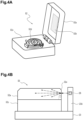
- the worker first draws all the tablet feeder storage portions 20A to 20C forward out of the medicine storage portion 13 after stopping operation of the tablet dispensing apparatus 10 [see Fig. 5A ].
- the tablet feeder storage portions 20C can be drawn out forward by inserting a key into the manual lock 43 on the front surface of the tablet feeder storage portion 20C to be drawn out [see Fig. 2E ] and turning the key [see Fig. 6D ] to manually unlock the tablet feeder storage portion 20C.
- the first side wall 35 is tilted [see Fig. 5D ].
- the first side wall 35 is maintained in the state of being slightly tilted, since the lower end portion of the first side wall 35 is loosely held by the side wall holding member 34.
- the first side wall 35 in that state can be easily removed from the frame member 31 by the worker lifting the first side wall 35.
- the worker can easily clean the first side wall 35 at a location away from the frame member 31.
Landscapes
- Engineering & Computer Science (AREA)
- Mechanical Engineering (AREA)
- Physics & Mathematics (AREA)
- General Physics & Mathematics (AREA)
- Health & Medical Sciences (AREA)
- Life Sciences & Earth Sciences (AREA)
- Animal Behavior & Ethology (AREA)
- General Health & Medical Sciences (AREA)
- Public Health (AREA)
- Veterinary Medicine (AREA)
- Basic Packing Technique (AREA)
- Medical Preparation Storing Or Oral Administration Devices (AREA)
Claims (15)
- Tablettenausgabegerät (10), umfassend:eine Mehrzahl von Tablettenzuführungs-Speicherbereichen (20), die dazu konfiguriert sind,
eine Mehrzahl von Tablettenzuführungen (52) zu speichern, und die in einer Linie in einer vertikalen Richtung angeordnet sind;einen oberen Tabletten-Sammelbereich (30), der entlang der Mehrzahl von Tablettenzuführungs-Speicherbereichen angeordnet ist und einen Tabletten-Fallpfad enthält, der Tabletten leitet und erlaubt, dass sie von der Mehrzahl von Tablettenzuführungs-Speicherbereichen nach unten fallen gelassen werden;einen Medikamenten-Speicherbereich (13), dazu konfiguriert, mindestens die Mehrzahl von Tablettenzuführungs-Speicherbereichen und den oberen Tabletten-Sammelbereich zu beherbergen;einen unteren Tabletten-Sammelbereich (16), der unterhalb des oberen Tabletten-Sammelbereichs angeordnet und dazu konfiguriert ist, die aus dem oberen Tabletten-Sammelbereich fallengelassenen Tabletten zu einem Ausgabebereich zu leiten;eine Mehrzahl von Speicherbereich-Gleitmechanismen (22), dazu konfiguriert, die Mehrzahl von Tablettenzuführungs-Speicherbereichen zu tragen, die individuell nach vorne gleiten können; undeinen Sammelbereich-Gleitmechanismus (37), dazu konfiguriert, den oberen Tabletten-Sammelbereich zu tragen, der unabhängig von der Mehrzahl der Tablettenzuführungs-Speicherbereichen nach vorne gleiten kann. - Tablettenausgabegerät nach Anspruch 1, ferner umfassend
eine ausziehbare Regulierungsstruktur (25), die es erlaubt, den oberen Tabletten-Sammelbereich nur dann nach vorne herauszuziehen, wenn die gesamte Mehrzahl von Tablettenzuführungs-Speicherbereichen nach vorne herausgezogen wird. - Tablettenausgabegerät nach Anspruch 1 oder 2, ferner umfassend:eine Mehrzahl von ausziehbaren Verrieglungsmechanismen (40), die entsprechend der Mehrzahl von Tablettenzuführungs-Speicherbereichen angeordnet und so konfiguriert sind, dass sie verhindern, dass die Mehrzahl von Tablettenzuführungs-Speicherbereichen jeweils entlang der Speicherbereich-Gleitmechanismen nach vorne gleitet.
- Tablettenausgabegerät nach Anspruch 3, ferner umfassend
einen Verriegelungszustand-Detektierbereich (46), dazu konfiguriert, zu detektieren, ob sich die Mehrzahl von ausziehbaren Verrieglungsmechanismen in einem verriegelten Zustand befinden oder nicht. - Tablettenausgabegerät nach Anspruch 3 oder 4, ferner umfassend
einen elektrischen Verriegelungsbetätigungsmechanismus (41, 42, 44), der elektrisch betrieben werden kann, und einen manuellen Verriegelungsbetätigungsmechanismus, der manuell betrieben werden kann, wobei:ein Hauptbereich des elektrischen Verriegelungsbetätigungsmechanismus an dem Medikamenten-Speicherbereich befestigt ist, und ein Hauptbereich des manuellen Verriegelungsbetätigungsmechanismus an den Tablettenzuführungs-Speicherbereichen befestigt ist; unddie ausziehbaren Verriegelungsmechanismen so konfiguriert sind, dass sie durch den Betrieb eines beliebigen von dem elektrischen Verriegelungsbetätigungsmechanismus und dem manuellen Verriegelungsbetätigungsmechanismus entriegelt werden können. - Tablettenausgabegerät nach einem der Ansprüche 1 bis 5, wobei:die Tablettenzuführungen jeweils so konfiguriert sind, dass sie eine Mehrzahl von Tabletten einer Art speichern können, die aus einer großen Anzahl von Arten von Tabletten unterschiedlicher Form und Größe ausgewählt sind, und die Funktion aufweisen, die Tabletten einzeln auszulassen; unddie Tablettenzuführungen und die Tablettenzuführungs-Speicherbereiche dazu konfiguriert sind, die Bereitstellung von Tabletten mit der Mehrzahl von Tablettenzuführungen zu erlauben, die an den Tablettenzuführungs-Speicherbereichen befestigt sind.
- Tablettenausgabegerät nach Anspruch 6, wobei:der Medikamenten-Speicherbereich eine Mehrzahl von Standard-Tablettenzuführungs-Speicherbereichen einschließlich einer Mehrzahl von Standard-Tablettenzuführungen beherbergt, die jeweils eine Tablettenkassette enthalten, die dazu konfiguriert ist, eine Mehrzahl von Tabletten derselben Form und Größe und derselben Art zu speichern, und einen oder mehrere obere Standard-Tabletten-Sammelbereiche, die entlang der Mehrzahl von Standard-Tablettenzuführungs-Speicherbereichen angeordnet sind und einen oder mehrere Tabletten-Fallpfade enthalten, die die Tabletten leiten und erlauben, dass sie von der Mehrzahl von Standard-Tablettenzuführungs-Speicherbereichen nach unten fallen gelassen werden;eine Mehrzahl von Zwischensammelbereichen, die zwischen dem einen oder mehreren oberen Standard-Tabletten-Sammelbereichen und dem oberen Tabletten-Sammelbereich, und dem untere Tabletten-Sammelbereich angeordnet sind, wobei die Mehrzahl von Zwischensammelbereichen dazu konfiguriert ist, die Mehrzahl von Tabletten, die von dem einen oder mehreren oberen Standard-Sammelbereichen fallen gelassen wurden, vorübergehend zu speichern; unddie Tabletten von der Mehrzahl von Zwischensammelbereichen zu dem unteren Tabletten-Sammelbereich fallen gelassen werden.
- Tablettenausgabegerät nach Anspruch 4, wobei:die Mehrzahl der Tablettenzuführungen jeweils einen Tabletten-Eingabeanschluss in einer oberen Oberfläche davon aufweisen;die Tablettenzuführungsbereiche jeweils eine Mehrzahl von Deckeln enthalten, die so betrieben werden können, dass sie die Tabletten-Eingabeanschlüsse der Mehrzahl von Tablettenzuführungen individuell öffnen und schließen; unddas Tablettenausgabegerät weiter einen Detektierbereich des Öffnungs-und Schließzustands des Deckels enthält, der dazu konfiguriert ist, zu detektieren, ob die Mehrzahl der Deckel in einem geöffneten oder geschlossenen Zustand sind.
- Tablettenausgabegerät nach Anspruch 8, wobei
der Detektierbereich des Öffnungs- und Schließzustands des Deckels so konfiguriert ist, dass er detektieren kann, ob die Deckel weit genug geöffnet sind oder nicht, um die Tabletten durch die Tabletten-Eingabanschlüsse einzugeben, und ob die Deckel komplett geschlossen sind oder nicht. - Tablettenausgabegerät nach Anspruch 8 oder 9, wobei
die Deckel jeweils aus einem transparenten Material gebildet sind, das einen Blick von oben in die Tablettenzuführungen erlaubt, und die Deckel jeweils mit einem Halbspiegel versehen sind, der so konfiguriert ist, dass er einen Blick von oben in die Tablettenzuführungen erlaubt und von unten nach oben gerichtetes Licht reflektiert. - Tablettenausgabegerät nach Anspruch 10, wobei:die Tablettenzuführungs-Speicherbereiche jeweils mit einer Mehrzahl von lichtemittierenden Vorrichtungen bereitgestellt sind, die in der Nähe der Mehrzahl von Tablettenzuführungen dazu bereitgestellt sind, zu leuchten, um eine Tablettenzuführung anzugeben, die mit den Tabletten ergänzt werden muss; unddie Deckel jeweils dazu konfiguriert sind, Licht von der entsprechenden lichtemittierenden Vorrichtung in die Tablettenzuführung einzuleiten.
- Tablettenausgabegerät nach Anspruch 11, wobei
die Deckel jeweils mit einem Lichtstreuungsbereich bereitgestellt sind, der dazu konfiguriert ist, Licht von den in den Tablettenzuführungen eingebrachten lichtemittierenden Vorrichtungen zu streuen. - Tablettenausgabegerät nach Anspruch 2, wobei
der obere Tabletten-Sammelbereich eine derartige Anordnungsstruktur aufweist, dass ein gegenüberliegender seitlicher Oberflächenbereich, der einem seitlichen Oberflächenbereich gegenüberliegt, der der Mehrzahl von Tablettenzuführungs-Speicherbereichen zugewandt ist, wenn der obere Tabletten-Sammelbereich nach vorne gezogen wird, ein Ausfließen von Pulver aus dem Tabletten-Fallpfad verhindert, wenn der obere Tabletten-Sammelbereich in dem Medikamenten-Speicherbereich untergebracht ist, und eine Reinigung des Tabletten-Fallpfads erlaubt, wenn der obere Tabletten-Sammelbereich aus dem Medikamenten-Speicherbereich herausgezogen wird. - Tablettenausgabegerät nach Anspruch 13, wobei
der gegenüberliegende seitliche Oberflächenbereich aus einem Plattenmaterial gebildet ist, das um einen unteren Endbereich davon in einer Richtung weg von der Mehrzahl der Tablettenzuführungs-Speicherbereiche zu neigen ist, wenn der obere Tabletten-Sammelbereich nach vorne gezogen wird. - Tablettenausgabegerät nach Anspruch 2, wobei:die Tablettenzuführungs-Speicherbereiche jeweils ein Regal umfassen, das von dem Speicherbereich-Gleitmechanismus getragen wird und an dem die Mehrzahl von Tablettenzuführungen in einer Reihe montiert ist, und ein Vorderpaneel, das an einem vorderen Endbereich des Regals angeordnet ist und sich in einer Richtung orthogonal zum Regal erstreckt; undein Teil des Vorderpaneels in Gleitrichtung des oberen Tabletten-Sammelbereichs nach vorne zeigt, um einen Teil der ausziehbaren Regulierungsstruktur zu bilden.
Applications Claiming Priority (3)
| Application Number | Priority Date | Filing Date | Title |
|---|---|---|---|
| JP2019150055A JP7204122B2 (ja) | 2019-08-19 | 2019-08-19 | 錠剤分包機 |
| JP2020021938A JP7396592B2 (ja) | 2020-02-12 | 2020-02-12 | 錠剤分包機 |
| PCT/JP2020/030997 WO2021033665A1 (ja) | 2019-08-19 | 2020-08-17 | 錠剤分包機 |
Publications (4)
| Publication Number | Publication Date |
|---|---|
| EP4018992A1 EP4018992A1 (de) | 2022-06-29 |
| EP4018992A4 EP4018992A4 (de) | 2023-11-15 |
| EP4018992B1 true EP4018992B1 (de) | 2024-12-04 |
| EP4018992C0 EP4018992C0 (de) | 2024-12-04 |
Family
ID=74661099
Family Applications (1)
| Application Number | Title | Priority Date | Filing Date |
|---|---|---|---|
| EP20854357.9A Active EP4018992B1 (de) | 2019-08-19 | 2020-08-17 | Tablettenausgabemaschine |
Country Status (6)
| Country | Link |
|---|---|
| US (1) | US20220280390A1 (de) |
| EP (1) | EP4018992B1 (de) |
| CN (1) | CN114269651B (de) |
| AU (1) | AU2020332158A1 (de) |
| CA (1) | CA3151893A1 (de) |
| WO (1) | WO2021033665A1 (de) |
Families Citing this family (3)
| Publication number | Priority date | Publication date | Assignee | Title |
|---|---|---|---|---|
| JP7493804B2 (ja) * | 2021-04-15 | 2024-06-03 | 株式会社トーショー | 薬剤分包機 |
| JP7664610B2 (ja) * | 2021-05-25 | 2025-04-18 | 株式会社トーショー | 薬剤分包機 |
| WO2023027581A1 (en) * | 2021-08-23 | 2023-03-02 | Vmi Holland B.V. | Filling station and method for filling a feeder unit with discrete medicaments |
Family Cites Families (17)
| Publication number | Priority date | Publication date | Assignee | Title |
|---|---|---|---|---|
| JP3222374B2 (ja) * | 1996-01-26 | 2001-10-29 | 株式会社湯山製作所 | 薬剤収納取り出し装置 |
| JP2001087353A (ja) * | 1999-09-17 | 2001-04-03 | Tosho Inc | 薬剤分包機 |
| US6585132B2 (en) * | 2001-09-24 | 2003-07-01 | Jun H. Kim | Tablet cassette assembly with slider cabinets for automatic tablet dispensing and packaging system |
| JP2003237702A (ja) | 2002-02-20 | 2003-08-27 | Sanyo Electric Co Ltd | 薬剤供給装置 |
| US7293672B2 (en) * | 2002-02-20 | 2007-11-13 | Sanyo Electric Co., Ltd. | Chemical feeding device |
| JP4484527B2 (ja) * | 2004-01-05 | 2010-06-16 | 株式会社トーショー | 自動調剤装置 |
| ATE477937T1 (de) * | 2004-10-08 | 2010-09-15 | Yuyama Mfg Co Ltd | Arzneimittelzufuhrvorrichtung |
| JP4437453B2 (ja) | 2005-04-08 | 2010-03-24 | 株式会社トーショー | 錠剤分包機 |
| JP5430450B2 (ja) * | 2010-03-05 | 2014-02-26 | 株式会社トーショー | 薬剤分包機 |
| AU2010347421C1 (en) * | 2010-03-05 | 2016-06-09 | Tosho, Inc. | Medicine Dispensing Apparatus |
| KR101715584B1 (ko) * | 2011-01-24 | 2017-03-14 | (주)제이브이엠 | 약제 자동 포장기 |
| JP5557819B2 (ja) | 2011-10-05 | 2014-07-23 | 株式会社トーショー | 錠剤分包機 |
| EP2765080A4 (de) * | 2011-10-05 | 2015-05-20 | Tosho Inc | Arzneimittelverpackungsvorrichtung |
| JP5557822B2 (ja) | 2011-10-17 | 2014-07-23 | 株式会社トーショー | 錠剤分包機 |
| KR102051802B1 (ko) * | 2012-11-19 | 2019-12-04 | (주)제이브이엠 | 약제 자동 포장기 |
| JP5950876B2 (ja) | 2013-07-25 | 2016-07-13 | 株式会社トーショー | 薬剤フィーダ |
| JP5839079B2 (ja) * | 2013-08-30 | 2016-01-06 | キヤノンマーケティングジャパン株式会社 | 錠剤供給装置、錠剤供給装置に着脱可能な着脱部材、及び錠剤供給システム |
-
2020
- 2020-08-17 CA CA3151893A patent/CA3151893A1/en active Pending
- 2020-08-17 US US17/635,913 patent/US20220280390A1/en not_active Abandoned
- 2020-08-17 CN CN202080058368.7A patent/CN114269651B/zh active Active
- 2020-08-17 EP EP20854357.9A patent/EP4018992B1/de active Active
- 2020-08-17 WO PCT/JP2020/030997 patent/WO2021033665A1/ja not_active Ceased
- 2020-08-17 AU AU2020332158A patent/AU2020332158A1/en active Pending
Also Published As
| Publication number | Publication date |
|---|---|
| WO2021033665A1 (ja) | 2021-02-25 |
| EP4018992A1 (de) | 2022-06-29 |
| CA3151893A1 (en) | 2021-02-25 |
| US20220280390A1 (en) | 2022-09-08 |
| CN114269651A (zh) | 2022-04-01 |
| AU2020332158A1 (en) | 2022-03-24 |
| EP4018992C0 (de) | 2024-12-04 |
| EP4018992A4 (de) | 2023-11-15 |
| CN114269651B (zh) | 2023-10-20 |
Similar Documents
| Publication | Publication Date | Title |
|---|---|---|
| EP4018992B1 (de) | Tablettenausgabemaschine | |
| KR102666501B1 (ko) | 정제 분포 장치 | |
| KR100744882B1 (ko) | 고형 제제 충전 장치 | |
| JP7204122B2 (ja) | 錠剤分包機 | |
| US20240238163A1 (en) | Medicine dispensing apparatus | |
| JP2011078598A (ja) | 自動薬剤供給装置 | |
| JP7396592B2 (ja) | 錠剤分包機 | |
| JP2004121376A (ja) | 物品投出装置 | |
| JP2011078599A (ja) | 自動薬剤供給装置および薬剤供給方法 | |
| AU2022257736A1 (en) | Medicine packaging machine | |
| JP7428423B1 (ja) | 薬剤供給装置 | |
| JP7777852B2 (ja) | 薬剤供給装置 | |
| JP7698302B2 (ja) | 薬剤供給装置 | |
| JP6694770B2 (ja) | 貨幣処理装置 | |
| JP7774846B2 (ja) | 薬剤供給装置 | |
| JP4540558B2 (ja) | ボトルフィーダ及びボトル払出装置ならびに薬品類払出システム | |
| JP2024043217A (ja) | 薬剤供給装置 | |
| JP2024043218A (ja) | 薬剤供給装置 | |
| JP7758327B2 (ja) | 薬剤供給装置 | |
| JP2024043221A (ja) | 薬剤供給装置 | |
| JP2024043219A (ja) | 薬剤供給装置 | |
| JP2023053606A (ja) | 薬剤供給装置 | |
| JP2024043216A (ja) | 薬剤供給装置 | |
| JP2024043220A (ja) | 薬剤供給装置 | |
| JP2023053610A (ja) | 薬剤供給装置 |
Legal Events
| Date | Code | Title | Description |
|---|---|---|---|
| STAA | Information on the status of an ep patent application or granted ep patent |
Free format text: STATUS: THE INTERNATIONAL PUBLICATION HAS BEEN MADE |
|
| PUAI | Public reference made under article 153(3) epc to a published international application that has entered the european phase |
Free format text: ORIGINAL CODE: 0009012 |
|
| STAA | Information on the status of an ep patent application or granted ep patent |
Free format text: STATUS: REQUEST FOR EXAMINATION WAS MADE |
|
| 17P | Request for examination filed |
Effective date: 20220317 |
|
| AK | Designated contracting states |
Kind code of ref document: A1 Designated state(s): AL AT BE BG CH CY CZ DE DK EE ES FI FR GB GR HR HU IE IS IT LI LT LU LV MC MK MT NL NO PL PT RO RS SE SI SK SM TR |
|
| DAV | Request for validation of the european patent (deleted) | ||
| DAX | Request for extension of the european patent (deleted) | ||
| A4 | Supplementary search report drawn up and despatched |
Effective date: 20231017 |
|
| RIC1 | Information provided on ipc code assigned before grant |
Ipc: G07F 17/00 20060101ALI20231011BHEP Ipc: G07F 11/60 20060101ALI20231011BHEP Ipc: B65B 65/08 20060101ALI20231011BHEP Ipc: B65B 37/16 20060101ALI20231011BHEP Ipc: B65B 5/10 20060101ALI20231011BHEP Ipc: B65B 59/04 20060101ALI20231011BHEP Ipc: B65B 1/30 20060101ALI20231011BHEP Ipc: A61J 3/00 20060101AFI20231011BHEP |
|
| GRAP | Despatch of communication of intention to grant a patent |
Free format text: ORIGINAL CODE: EPIDOSNIGR1 |
|
| STAA | Information on the status of an ep patent application or granted ep patent |
Free format text: STATUS: GRANT OF PATENT IS INTENDED |
|
| INTG | Intention to grant announced |
Effective date: 20240715 |
|
| GRAS | Grant fee paid |
Free format text: ORIGINAL CODE: EPIDOSNIGR3 |
|
| GRAA | (expected) grant |
Free format text: ORIGINAL CODE: 0009210 |
|
| STAA | Information on the status of an ep patent application or granted ep patent |
Free format text: STATUS: THE PATENT HAS BEEN GRANTED |
|
| AK | Designated contracting states |
Kind code of ref document: B1 Designated state(s): AL AT BE BG CH CY CZ DE DK EE ES FI FR GB GR HR HU IE IS IT LI LT LU LV MC MK MT NL NO PL PT RO RS SE SI SK SM TR |
|
| REG | Reference to a national code |
Ref country code: CH Ref legal event code: EP |
|
| REG | Reference to a national code |
Ref country code: DE Ref legal event code: R096 Ref document number: 602020042701 Country of ref document: DE |
|
| REG | Reference to a national code |
Ref country code: IE Ref legal event code: FG4D |
|
| U01 | Request for unitary effect filed |
Effective date: 20241204 |
|
| U07 | Unitary effect registered |
Designated state(s): AT BE BG DE DK EE FI FR IT LT LU LV MT NL PT RO SE SI Effective date: 20241213 |
|
| PG25 | Lapsed in a contracting state [announced via postgrant information from national office to epo] |
Ref country code: HR Free format text: LAPSE BECAUSE OF FAILURE TO SUBMIT A TRANSLATION OF THE DESCRIPTION OR TO PAY THE FEE WITHIN THE PRESCRIBED TIME-LIMIT Effective date: 20241204 |
|
| PG25 | Lapsed in a contracting state [announced via postgrant information from national office to epo] |
Ref country code: ES Free format text: LAPSE BECAUSE OF FAILURE TO SUBMIT A TRANSLATION OF THE DESCRIPTION OR TO PAY THE FEE WITHIN THE PRESCRIBED TIME-LIMIT Effective date: 20241204 |
|
| PG25 | Lapsed in a contracting state [announced via postgrant information from national office to epo] |
Ref country code: GR Free format text: LAPSE BECAUSE OF FAILURE TO SUBMIT A TRANSLATION OF THE DESCRIPTION OR TO PAY THE FEE WITHIN THE PRESCRIBED TIME-LIMIT Effective date: 20250305 |
|
| PG25 | Lapsed in a contracting state [announced via postgrant information from national office to epo] |
Ref country code: RS Free format text: LAPSE BECAUSE OF FAILURE TO SUBMIT A TRANSLATION OF THE DESCRIPTION OR TO PAY THE FEE WITHIN THE PRESCRIBED TIME-LIMIT Effective date: 20250304 |
|
| PG25 | Lapsed in a contracting state [announced via postgrant information from national office to epo] |
Ref country code: SM Free format text: LAPSE BECAUSE OF FAILURE TO SUBMIT A TRANSLATION OF THE DESCRIPTION OR TO PAY THE FEE WITHIN THE PRESCRIBED TIME-LIMIT Effective date: 20241204 |
|
| PG25 | Lapsed in a contracting state [announced via postgrant information from national office to epo] |
Ref country code: PL Free format text: LAPSE BECAUSE OF FAILURE TO SUBMIT A TRANSLATION OF THE DESCRIPTION OR TO PAY THE FEE WITHIN THE PRESCRIBED TIME-LIMIT Effective date: 20241204 |
|
| PG25 | Lapsed in a contracting state [announced via postgrant information from national office to epo] |
Ref country code: IS Free format text: LAPSE BECAUSE OF FAILURE TO SUBMIT A TRANSLATION OF THE DESCRIPTION OR TO PAY THE FEE WITHIN THE PRESCRIBED TIME-LIMIT Effective date: 20250404 |
|
| PG25 | Lapsed in a contracting state [announced via postgrant information from national office to epo] |
Ref country code: SK Free format text: LAPSE BECAUSE OF FAILURE TO SUBMIT A TRANSLATION OF THE DESCRIPTION OR TO PAY THE FEE WITHIN THE PRESCRIBED TIME-LIMIT Effective date: 20241204 |
|
| PG25 | Lapsed in a contracting state [announced via postgrant information from national office to epo] |
Ref country code: CZ Free format text: LAPSE BECAUSE OF FAILURE TO SUBMIT A TRANSLATION OF THE DESCRIPTION OR TO PAY THE FEE WITHIN THE PRESCRIBED TIME-LIMIT Effective date: 20241204 |
|
| PLBE | No opposition filed within time limit |
Free format text: ORIGINAL CODE: 0009261 |
|
| STAA | Information on the status of an ep patent application or granted ep patent |
Free format text: STATUS: NO OPPOSITION FILED WITHIN TIME LIMIT |
|
| 26N | No opposition filed |
Effective date: 20250905 |